Page 1
Aerosol and Air Quality Research, 20: 2681–2689, 2020
ISSN: 1680-8584 print / 2071-1409 online Publisher: Taiwan Association for Aerosol Research
https://doi.org/10.4209/aaqr.2020.05.0191
Copyright The Author(s). This is an open access article distributed under the terms of the Creative Commons Attribution License (CC BY 4.0), which permits unrestricted use, distribution, and reproduction in any medium, provided the original author and source are cited.
Performance Investigation of a Vertical Wave-plate Mist Eliminator with
Perforated Plates
Seung-Yoon Noh1, Moon-Won Kim2, Se-Jin Yook1,2*
1 School of Mechanical Engineering, Hanyang University, Seoul, Korea 2 Department of Convergence Defense, Hanyang University, Seoul, Korea
ABSTRACT
This study improved collection efficiency of the mist eliminator used for wet flue gas desulfurization facilities. The
commonly used wave-plate mist eliminator with a drainage channel was chosen as a reference model and its performance
was compared with the performance of a wave-plate mist eliminator with perforated plates attached to the front of each
drainage channel. Simulations were performed to compare the dust collection performance of the mist eliminators. We could
confirm that the addition of perforated plates to the mist eliminator changed the particle behavior in front of the drainage
channel and induced the passage of particles through the mist eliminator and into the drainage channel. Subsequent
experiments confirmed that dust collection performance was improved with the use of the perforated plates. The use of the
mist eliminator designed in this study is expected to greatly reduce the amount of air pollutants emitted from various
industrial facilities.
Keywords: Aerosol; Mist eliminator; Inertial separator; Collection efficiency.
INTRODUCTION
Recently, as the number of days with high concentration
of fine dust particles, defined as particulate matter (PM) that
is less than 10 µm, in the air has increased, there has been
greater interest in the study of fine dust. Studies worldwide
have reported that fine dust may adversely affect human
health. It has also been found that fine dust can cause lung
cancer (Pope et al., 2002), and death due to respiratory diseases
have been shown to be closely related to atmospheric PM2.5
concentrations (Guaita et al., 2011; Perez et al., 2012; Kim
et al., 2018). In addition, exposure to fine dust can lead to a
variety of diseases, including cardiovascular disease, bronchial
asthma, atherosclerosis, premature death, and birth defects
(Basu et al., 2014; Kang and Kim, 2014; Lung et al., 2016);
therefore, it is essential to investigate ways to reduce the
atmospheric concentration of fine dust. Atmospheric fine dust
is emitted from various industrial and living environments.
In particular, various studies show that particulate matter is
generated during power generation processes that use fossil
fuels, such as coal-fired power plants. Consequently, it was
confirmed that a large amount of fine dust of PM10 and PM2.5
is released (Zhang et al., 2005; Goodarzi, 2006; Din et al.,
* Corresponding author.
Tel.: +82-2-2220-0422; Fax: +82-2-2220-2299
E-mail address: [email protected]
2013; Manousakas et al., 2013; Lu et al., 2019). In order to
reduce the emissions of fine dust and SOx, a thermal power
plant is generally equipped with a selective catalytic
reduction system, an electrostatic precipitator, and a flue gas
desulfurization (FGD) facility. A mist eliminator is installed
in the FGD to remove droplets used for absorbing SOx (Kim
et al., 2019).
If the collection efficiency of the mist eliminator, which
is involved in the collection of fine dust, can be improved, it
can greatly contribute to the reduction of particulate matter
emissions from thermal power plants. Therefore, various
studies on mist eliminators have been conducted. An
electrostatic mist eliminator, that has a low differential
pressure and can improve the collection efficiency of fine
dust, was developed by Kim et al. (2019), and the collection
efficiency was compared based on the structure of the
drainage channel of the mist eliminator. A study by James et
al. (2003) showed that higher collection efficiencies were
observed for the same flow rate, when drainage channels
were included. The collection efficiencies of horizontal and
vertical arrays of wire mesh, in mist eliminators, were
compared in a study by Brunazzi and Paglianti (1998). The
collection efficiencies, according to vane spacing and vane
turning angle of the mist eliminator, were compared in a
study by Narimani and Shahhoseini (2011), and collection
efficiency was highest at a vane spacing of 20 mm, flow rate
of 5 m s–1, and vane angle of 60°. Three types of vertical
mist eliminators, knitted wire mesh, crushed aluminum
turnings, and multiple pass louvers, were compared under
Page 2
Noh et al., Aerosol and Air Quality Research, 20: 2681–2689, 2020
2682
the same differential pressure or at the same flow rate by
Bell and Strauss (1973). This study showed that under the
same differential pressure, the collection efficiency was
highest in the knitted wire mesh; and at the same flow rate,
it was highest in the louver eliminator. Three different
models of axial cyclone mist eliminators were designed and
compared experimentally by Brunazzi et al. (2003). The
collection efficiencies of five drift mist eliminators, bent into
different models, were compared by Zamora and Kaiser (2011).
Wave-plate mist eliminators with two different widths and
channel numbers were compared by Galletti et al. (2008)
through a simulation, and the collection efficiency was
higher in large and wide models at the same inlet flow rate.
The effects of the wire diameter and the packing density on
the collection efficiency in the wire mesh eliminator were
analyzed by Al-Daughaither et al. (2010), and the collection
efficiency increased when wire diameter was decreased and
the packing density increased. Recently, double pocket vane
mist eliminator was developed and commercialized by many
companies due to its large capacity and good separation
efficiency (Chandranegara, 2016; Dries and Hoffmann, 2019).
Previous studies have focused on improving dust collection
efficiency by changing the design model of existing mist
eliminators. Because the mist eliminator with drainage
channels has been proven to be efficient in increasing
separation efficiency for small droplets (Chandranegara,
2016), this study aimed at improving the performance of the
mist eliminator with drainage channels. Therefore, as shown
in Fig. 1(a), the wave-plate mist eliminator model, which is
one of the basic models of the mist eliminator, was set as a
reference for the design of a new model. This reference mist
eliminator model was also used in various previous studies
(James et al., 2003; Galletti et al., 2008; Narimani and
Shahhoseini, 2011; Zamora and Kaiser, 2011). The newly
designed mist eliminator model in this study is shown in
Fig. 1(b), in which an additional plate with rectangular
perforation was installed in front of the drainage channel of
the reference model. The dimensions of the reference and
the new mist eliminator are shown in Table 1. The optimized
model of the perforated plate used in this study was derived
through the simulation method. Consequently, a mist
eliminator was created to place the perforated plate structure
in front of each drainage channel and the collection efficiency
was measured and compared through experiments.
NUMERICAL METHOD
In order to analyze the characteristics of the flow,
according to the inlet flow rates of the mist eliminator, and
to predict the collection efficiency, according to the changes
in the characteristics of the flow, a numerical analysis was
performed using ANSYS FLUENT Release 17.0. Since the
Fig. 1. Geometry of mist eliminator. (a) Reference mist eliminator, (b) Mist eliminator with perforated plates.
Table 1. Detailed dimensions of the mist eliminator.
Parameter Reference Mist Eliminator Mist Eliminator with Perforated Plates
ɵ 45° 45°
a 8.6 mm 8.6 mm
b 4.3 mm 4.3 mm
c - 8.6 mm
d 118.5 mm 118.5 mm
g - 4.3 mm
w 150 mm 150 mm
Page 3
Noh et al., Aerosol and Air Quality Research, 20: 2681–2689, 2020
2683
mist eliminator model used in the actual wet flue gas
desulfurization system has the same cross-sectional model
that is repeated many times, two-dimensional (2D) analysis
conditions were used to predict the performance of the mist
eliminator. For reference, previous studies analyzing the dust
collection efficiency of mist eliminators, using numerical
analysis, have performed 2D analysis on only one of the six
channels shown in Fig. 1(a) (James et al., 2003; James et al.,
2005; Galletti et al., 2008). Flow was set to run from bottom
to top. The flow in the mist eliminator is assumed to be
steady, incompressible, and turbulent. The Reynolds Stress
Method (RSM) model was used for turbulent flow analysis
(Rafee et al., 2010; Estakhrsar and Rafee, 2013). The SIMPLE
algorithm was used for pressure-velocity coupling.
The second-order upwind scheme was selected to solve
the momentum equation, and to calculate the turbulent
kinetic energy and turbulent dissipation rate. The boundary
conditions for flow analysis at the flow inlet and outlet of
the computational domain were, respectively, the velocity inlet
and pressure outlet conditions, while the no-slip conditions
were set at the wall of the absorption tower chamber and the
surface of the mist eliminator. The flow rate of air flowing
into the mist eliminator, through the inlet of the computational
zone, was set to 2−5 m s–1, which is the flow rate of the
commonly used wet flue gas desulfurization absorption tower
(James et al., 2003; Kavousi et al., 2013). Structured grids
were generated, and y+ values were set to be lower than 1
(Galletti et al., 2008). As a result of the grid independence
test, about 85,000 grids were selected. Based on the approaches
of previous literature (Zamora and Kaiser, 2011; Estakhrsar
and Rafee, 2013), the convergence criteria of the flow analysis
were set so that all equations converged to 10–5 and all relative
errors fell below 10–5 in the present study’s simulations.
After the flow analysis was completed, particle behavior
was analyzed using Discrete Phase Models (DPM), a
particulate behavior analysis code embedded in FLUENT.
For particulate behavior analysis, it was assumed that the
particles were spherical and had a density of 1 g/cm3. Stokes'
drag force, operated by the relative flow of particles in the
fluid, was taken into consideration, and the drag force was
corrected using the slip correction factor according to the
particle size (Kim et al., 2005). The number of particles
released from the inlet of the mist eliminator channel was set
to be 2500. Due to the mist eliminator being modeled
vertically, a downward gravitational force was taken into
consideration. In order to account for the effects of the
turbulent dispersion of particles, this study employed the
discrete random walk (DRW) model, which calculates
particle trajectories in a stochastic way by considering the
fluctuations of turbulent flow velocity (ANSYS FLUENT
User’s Guide 15.0, 2013). In addition, it was assumed that
all walls in the mist eliminator were applied with trap
conditions and therefore it was assumed that the particles
were trapped on the wall when they hit the wall.
EXPERIMENTAL METHOD
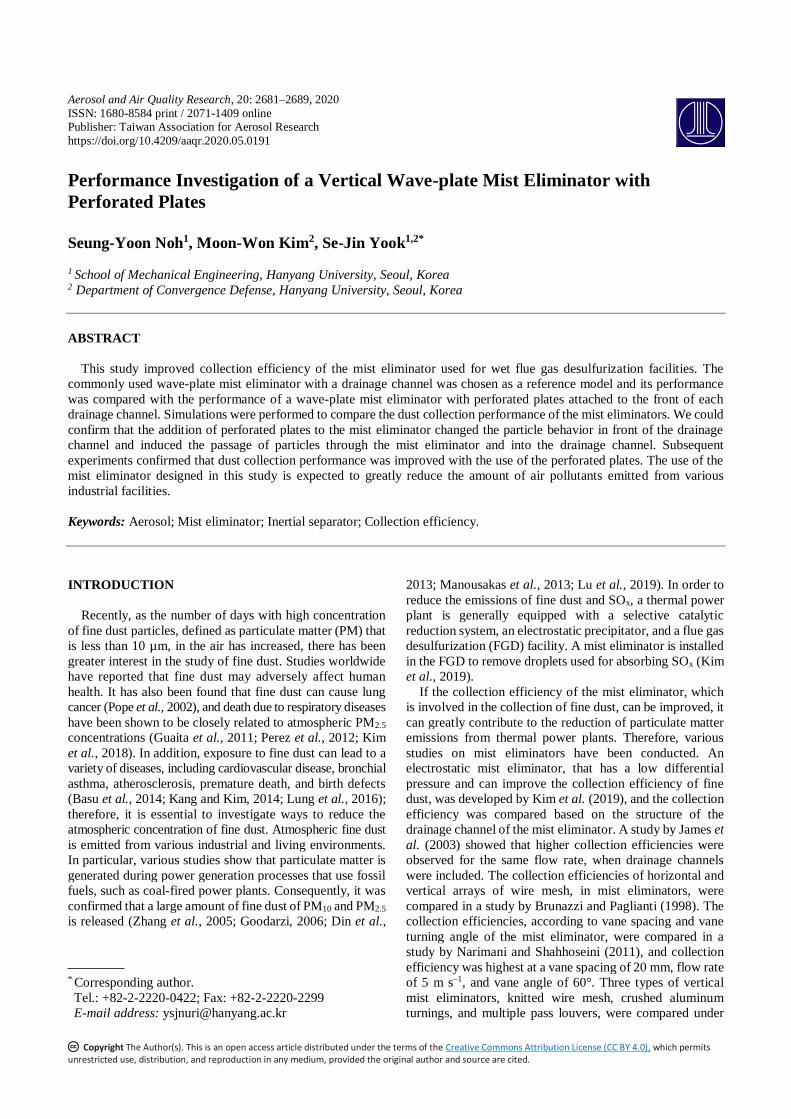
Fig. 2 shows a photograph of a mist eliminator with
perforated plates as designed in this study. The mist eliminator
Fig. 2. Manufactured mist eliminator module.
was made of acrylic and consisted of six channels. The total
height of the mist eliminator was 0.25 m, the width of each
channel was 0.025 m, and the total width of the six channels
was 0.15 m. When no perforated plate was installed in front
of the drainage channel, the model looked like Fig. 1(a) and
when it was installed it looked like Fig. 1(b).
To verify the effect of removing particulate matter by the
constructed mist eliminator, we used two types of experiment
setups shown in Figs. 3 and 4. The height of the lab-scale
chamber, which simulates the absorption tower of the wet
flue gas desulfurization facility where the mist eliminator is
installed, was 1.2 m, and the gas flow rate inside the absorption
tower was set to 2.5 m s–1. In a lab-scale chamber equipped
with a mist eliminator, the flow was set to run vertically from
bottom to top. Since the purpose of this study was to test the
particle removal characteristics of the perforated plate equipped
mist eliminator used in wet flue gas desulfurization, the
chemical reaction to remove sulfur compounds was not
considered. That is, instead of flue gas containing the sulfur
compound, clean air that has passed through the High
Efficiency Particulate Air (HEPA) filter was injected into
the absorption tower.
The experiment setup to compare the collection efficiency
is shown in Fig. 3, and instead of spraying limestone slurry
to measure the collection efficiency of the mist eliminator,
the Solid Aerosol Generator (SAG 410, TOPAS, Germany)
was used to aerosolize Arizona Test Dust (ISO 12103–1, A4
type). The dust aerosol was injected into the absorption
tower with clean air. Arizona Test Dust, before and after the
flow containing particles passed through the mist eliminator,
was sampled at an aerosolized state and was used to measure
the number concentration distribution using an Optical
Page 4
Noh et al., Aerosol and Air Quality Research, 20: 2681–2689, 2020
2684
Fig. 3. Experimental setup for measuring collection efficiency.
Fig. 4. Experimental setup for SEM analysis.
Particle Counter (OPC, Model 1.109, GRIMM, Germany).
The following equation was used to determine the collection
efficiency (η) of the mist eliminator.
1after
before
C
C (1)
Here, Cbefore and Cafter are, respectively, the aerosol
number concentrations before and after the flow containing
the particles passed through the mist eliminator. In addition,
the density and dynamic shape factor of the Arizona Test
Dust were set to 2.65 g cm–3 and 1.6, respectively, and the
particle size measured by OPC was converted into aerodynamic
diameter using the following equation (Fletcher and Bright,
2000).
0 aeve ae
p ve
Cd d
C
(2)
Page 5
Noh et al., Aerosol and Air Quality Research, 20: 2681–2689, 2020
2685
Here, ρ0 is 1 g cm–3, ρp is 2.65 g cm–3 for the density of
Arizona Test Dust, Cae and Cve are slip correction factors for
aerodynamic diameter and volume equivalent diameter, and
χ is 1.6, the dynamic shape factor for Arizona Test Dust
(Peters et al., 2006).
Next, the limestone slurry was sprayed in the absorption
tower chamber and experiment was performed to examine
the efficiency with which the sprayed limestone slurry was
removed by the mist eliminator. The experimental set-up for
comparing the removal effect of limestone slurry in the actual
reference mist eliminator model and the mist eliminator
model with the perforated plate design of this study, are
shown in Fig. 4. In order to generate the slurry particles used
in the experiment, limestone powder (SSM-20, Seongshin
Minefield, Korea) with an average particle size of 20 µm
was mixed with water in a ratio of 2:3 to create a slurry, and
placed in a 100 L tank to prevent the precipitation of limestone
powder and was stirred using an agitator (BL1003D, MTOPS,
Korea). As shown in Fig. 4, limestone slurry was sprayed
downwards using a full cone nozzle (KJ1/2FF-SS32, Kukje
Nozzle, South Korea) into clean air filtered through a HEPA
filter flowing from the bottom to top. At this time, the spray
operation pressure was set to 3 bar. Sprayed limestone slurry
particles were collected on a Transmission Electron
Microscope (TEM) grid using a Mini Particle Sampler
(MPS, Domaine Technologique, France) at locations before
and after the flow containing the particles passed through the
mist eliminator. Then, the morphology and amount of
particles collected on the TEM grid were analyzed using a
Scanning Electron Microscope (S4800, HITACHI, Japan).
RESULTS AND DISCUSSION
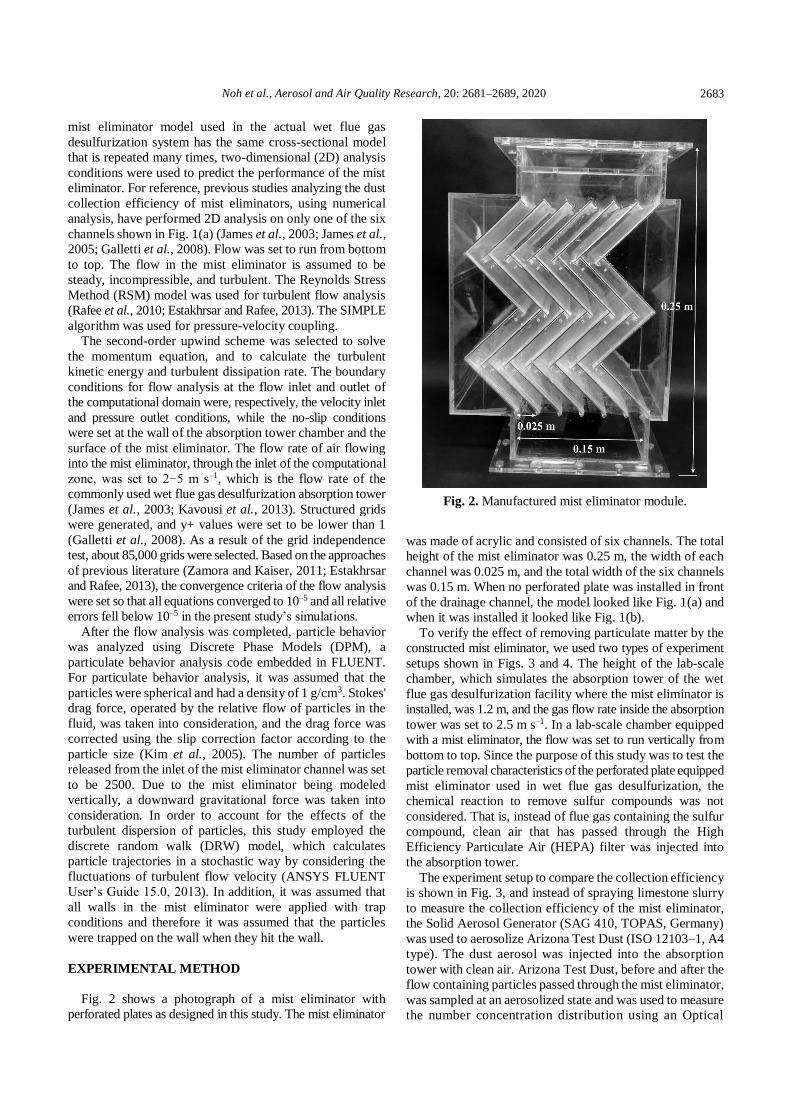
In order to confirm the accuracy of the predictions of the
numerical analysis, experiments were conducted using Arizona
Test Dust to quantitatively compare the collection efficiency.
Fig. 5 is a graph comparing the collection efficiency
according to aerodynamic diameter when the flow rate at the
inlet of the mist eliminator is 2.5 m s–1 for both the reference
model and the model including the perforated plate. As
shown in Fig. 5, the simulation results were similar to the
experimental results. The numerically predicted collection
efficiencies were slightly higher than the experimental data
for particle sizes in the range of about 5–12 µm. This might
be due to the fact that the simulation assumed the particles
to be trapped on all walls including the side walls whereas
in the experiment the particles which were not collected in
the drainage channel could be re-suspended after they hit the
side walls. The cut-off size of the reference model was about
5 µm, whereas the cut-off size of the mist eliminator model
with the perforated plate design of this study was around 2
µm. Therefore, the model with the perforated plate design of
this study demonstrated a better dust collection performance
than the reference model.
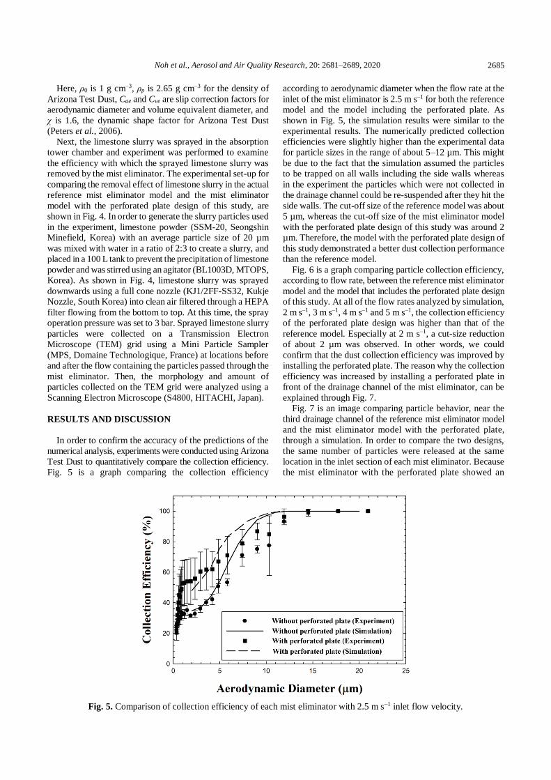
Fig. 6 is a graph comparing particle collection efficiency,
according to flow rate, between the reference mist eliminator
model and the model that includes the perforated plate design
of this study. At all of the flow rates analyzed by simulation,
2 m s–1, 3 m s–1, 4 m s–1 and 5 m s–1, the collection efficiency
of the perforated plate design was higher than that of the
reference model. Especially at 2 m s–1, a cut-size reduction
of about 2 µm was observed. In other words, we could
confirm that the dust collection efficiency was improved by
installing the perforated plate. The reason why the collection
efficiency was increased by installing a perforated plate in
front of the drainage channel of the mist eliminator, can be
explained through Fig. 7.
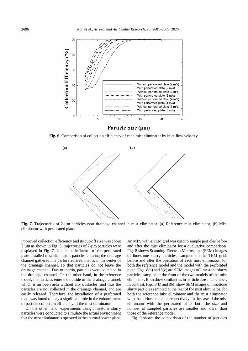
Fig. 7 is an image comparing particle behavior, near the
third drainage channel of the reference mist eliminator model
and the mist eliminator model with the perforated plate,
through a simulation. In order to compare the two designs,
the same number of particles were released at the same
location in the inlet section of each mist eliminator. Because
the mist eliminator with the perforated plate showed an
Fig. 5. Comparison of collection efficiency of each mist eliminator with 2.5 m s–1 inlet flow velocity.
Page 6
Noh et al., Aerosol and Air Quality Research, 20: 2681–2689, 2020
2686
Fig. 6. Comparison of collection efficiency of each mist eliminator by inlet flow velocity.
Fig. 7. Trajectories of 2-µm particles near drainage channel in mist eliminator. (a) Reference mist eliminator, (b) Mist
eliminator with perforated plate.
improved collection efficiency and its cut-off size was about
2 µm as shown in Fig. 5, trajectories of 2-µm particles were
displayed in Fig. 7. Under the influence of the perforated
plate installed mist eliminator, particles entering the drainage
channel gathered in a perforated area, that is, in the center of
the drainage channel, so that particles do not leave the
drainage channel. Due to inertia, particles were collected in
the drainage channel. On the other hand, in the reference
model, the particles enter the outside of the drainage channel,
which is an open area without any obstacles, and thus the
particles are not collected in the drainage channel, and are
easily released. Therefore, the installation of a perforated
plate was found to play a significant role in the enhancement
of particle collection efficiency of the mist eliminator.
On the other hand, experiments using limestone slurry
particles were conducted to simulate the actual environment
that the mist eliminator is operated in the thermal power plant.
An MPS with a TEM grid was used to sample particles before
and after the mist eliminator for a qualitative comparison.
Fig. 8 shows Scanning Electron Microscope (SEM) images
of limestone slurry particles, sampled on the TEM grid,
before and after the operation of each mist eliminator, for
both the reference model and the model with the perforated
plate. Figs. 8(a) and 8(c) are SEM images of limestone slurry
particles sampled at the front of the two models of the mist
eliminator. Both show similarities in particle size and number.
In contrast, Figs. 8(b) and 8(d) show SEM images of limestone
slurry particles sampled at the rear of the mist eliminator, for
both the reference mist eliminator and the mist eliminator
with the perforated plate, respectively. In the case of the mist
eliminator with the perforated plate, both the size and
number of sampled particles are smaller and lower than
those of the reference model.
Fig. 9 shows the comparison of the number of particles
Page 7
Noh et al., Aerosol and Air Quality Research, 20: 2681–2689, 2020
2687
Fig. 8. SEM image (2000x magnification) of particles deposited on the TEM grid: (a) Upstream of reference mist eliminator
case; (b) Downstream of reference mist eliminator case; (c) Upstream of mist eliminator with perforated plate case;
(d) Downstream of mist eliminator with perforated plate case.
Fig. 9. Comparison of the number of particles deposited on the TEM grids installed upstream and downstream of the mist
eliminators.
deposited on the TEM grids installed upstream and downstream
of the mist eliminators with and without the perforated plate.
For this quantitative comparison, several SEM images for
each mist eliminator type were analyzed. The two mist
eliminators showed very similar upstream conditions, however
it is clearly seen that the number of particles sampled
downstream of the mist eliminator with the perforated plate
was much lower than that of the reference mist eliminator.
These results are consistent with the results in Fig. 8, which
means that the mist eliminator with the perforated plate
designed in this study will be effective in the removal of
particulate matter, even when applied to actual thermal
power plants.
Page 8
Noh et al., Aerosol and Air Quality Research, 20: 2681–2689, 2020
2688
CONCLUSIONS
In this study, we investigated a method for improving dust
collection efficiency, by modifying the basic wave-plate
mist eliminators installed in the wet flue gas desulfurization
facility of thermal power plants, to remove particulate
matter. Each bent area of the wave-plate mist eliminator was
equipped with a drainage channel to collect particulate
matter via inertia. Additionally, a perforated plate was
installed at the front of each drainage channel to further
enhance the inertial dust collection effect. First, a simulation
was used to predict the dust collection efficiency of the mist
eliminator with the perforated plate and the reference mist
eliminator, at flow rates between 2–5 m s–1. The results
showed that the collection efficiency, of the model with the
perforated plate, was higher for all flow rates tested. The
accuracy of these simulation results was verified through
experiments with Arizona Test Dust. In addition, to simulate
the actual operational conditions of the mist eliminator in
thermal power plants, limestone slurry particles were used
to qualitatively compare the collection performance of mist
eliminators. As a result, smaller and fewer limestone slurry
particles exited the mist eliminator in the model with the
perforated plate in comparison to the reference model. This
study showed that mist eliminators actually used in real
thermal power plants could be additionally equipped with
perforated plates to increase the collection efficiency of the
mist eliminator. A systematic parametric study needs to be
conducted to characterize the performance of the suggested
mist eliminator design using non-dimensional numbers. The
mist eliminator model with the perforated plate proposed in
this study can be applied in a simple manner to the existing
wave-plate mist eliminator, and is expected to contribute
greatly to the reduction of particulate matter emitted from
various thermal power plants or industrial facilities.
Additionally, for the mist eliminator of a shape other than
wave-plate, future study is needed to improve dust collection
efficiency through simple shape deformation.
ACKNOWLEDGMENT
This research was supported by the Ministry of
Environment as part of the “Korea Environmental Industry
& Technology Institute (KEITI) (No. 2018000120004).
REFERENCES
Al-Dughaither, A.S., Ibrahim, A.A. and Al-Masry, W.A.
(2010). Investigating droplet separation efficiency in
wire-mesh mist eliminators in bubble column. J. Saudi
Chem. Soc. 14: 331–339. https://doi.org/10.1016/j.jscs.20
10.04.001
ANSYS FLUENT Users Guide 15.0. (2013). Modeling
Discrete Phase. FLUENT, Inc., Lebanon, NH, Chap. 24.
Basu, R., Harris, M., Sie, L., Malig, B., Broadwin, R. and
Green, R. (2014). Effects of fine particulate matter and its
constituents on low birth weight among full-term infants
in California. Environ. Res. 128: 42–51. https://doi.org/1
0.1016/j.envres.2013.10.008
Bell, C.G. and Strauss, W. (1973). Effectiveness of vertical
mist eliminators in a cross flow scrubber. J. Air Pollut.
Control Assoc. 23: 967–969. https://doi.org/10.1080/000
22470.1973.10469867
Brunazzi, E. and Paglianti, A. (1998). Design of wire mesh
mist eliminators. AIChE J. 44: 505–512. https://doi.org/1
0.1002/aic.690440302
Brunazzi, E., Paglianti, A. and Talamelli, A. (2003).
Simplified design of axial-flow cyclone mist eliminators.
AIChE J. 49: 41–51. https://doi.org/10.1002/aic.690490106
Chandranegara, A.S. (2016). Review: Improving mist
eliminator performance in gas-liquid separators.
Unpublished. https://doi.org/10.13140/RG.2.1.3342.4885
Din, S.A.M., Yahya, N.N.H.N. and Abdullah, A. (2013).
Fine particulates matter (PM2.5) from coal-fired power
plant in Manjung and its health impacts. Procedia Soc.
Behav. Sci. 85: 92–99. https://doi.org/10.1016/j.sbspro.2
013.08.341
Dries, H.W. and Hoffmann, A.C. (2019). A correlation
giving improved description of the capacity and
efficiency of vane-type gas–liquid separators. AIChE J.
65: e16566. https://doi.org/10.1002/aic.16566
Estakhrsar, M.H.H. and Rafee, R. (2013). Effect of drainage
channel dimensions on the performance of wave-plate
mist eliminators. Korean J. Chem. Eng. 30: 1301–1311.
https://doi.org/10.1007/s11814-013-0032-9
Fletcher, RA. and Bright, D.S. (2000). Shape factors of ISO
12103-A3 (medium test dust). Filtr. Sep. 37: 48–56.
https://doi.org/10.1016/S0015-1882(00)80200-1
Galletti, C., Brunazzi, E. and Tognotti, L. (2008). A
numerical model for gas flow and droplet motion in wave-
plate mist eliminators with drainage channels. Chem. Eng.
Sci. 63: 5639–5652. https://doi.org/10.1016/j.ces.2008.0
8.013
Goodarzi, F. (2006). Morphology and chemistry of fine
particles emitted from a Canadian coal-fired power plant.
Fuel 85: 273–280. https://doi.org/10.1016/j.fuel.2005.07.
004
Guaita, R., Pichiule, M., Maté, T., Linares, C. and Díaz, J.
(2011). Short-term impact of particulate matter (PM2.5) on
respiratory mortality in Madrid. Int. J. Environ. Health
Res. 21: 260–274. https://doi.org/10.1080/09603123.201
0.544033
James, P.W., Wang, Y., Azzopardi, B.J. and Hughes, J.P.
(2003). The role of drainage channels in the performance
of wave-plate mist eliminators. Chem. Eng. Res. Des. 81:
639–648. https://doi.org/10.1205/026387603322150499
James, P.W., Azzopardi, B.J., Wang, Y. and Hughes, J.P.
(2005). A model for liquid film flow and separation in a
wave-plate mist eliminator. Chem. Eng. Res. Des. 83:
469–477. https://doi.org/10.1205/cherd.03363
Kang, D. and Kim, J.E. (2014). Fine, ultrafine, and yellow dust:
Emerging health problems in Korea. J. Korean Med. Sci.
29: 621–622. https://doi.org/10.3346/jkms.2014.29.5.621
Kavousi, F., Behjat, Y. and Shahhosseini, S. (2013).
Optimal design of drainage channel geometry parameters
in vane demister liquid–gas separators. Chem. Eng. Res.
Des. 91: 1212–1222. https://doi.org/10.1016/j.cherd.2013.
01.012
Page 9
Noh et al., Aerosol and Air Quality Research, 20: 2681–2689, 2020
2689
Kim, H.J., Kim, J.S., Han, B. and Kim, Y.J. (2019). Mist
removal performance of a novel electrostatic precipitation
type mist eliminator with a narrow gap at high velocity
for coal-fired power plant. 2019 IEEE Industry
Applications Society Annual Meeting, Baltimore, MD,
USA, pp. 1–9.
Kim, J.H., Mulholland, G.H., Kukuck, S.R. and Pui, D.Y.H.
(2005). Slip correction measurements of certified PSL
nanoparticles using a nanometer differential mobility
analyzer (nano-DMA) for Knudsen number from 0.5 to
83. J. Res. Natl. Inst. Stand. Technol. 110: 31–54.
https://doi.org/10.6028/jres.110.005
Kim, T.Y., Kim, H., Yi, S.M., Cheong, J.P. and Heo, J.
(2018). Short-term effects of ambient PM2.5 and PM2.5-10
on mortality in major cities of Korea. Aerosol Air Qual.
Res. 18: 1853–1862. https://doi.org/10.4209/aaqr.2017.1
1.0490
Lu, H.Y., Wu, Y.L., Mutuku, J.K. and Chang, K.H. (2019).
Various sources of PM2.5 and their impact on the air
quality in Tainan city, Taiwan. Aerosol Air Qual. Res. 19:
601–619. https://doi.org/10.4209/aaqr.2019.01.0024
Lung, C.C., Chen, S.C., Yang, C.H., Chen, Y.C., Chang,
S.Y., Tseng, W.C. and Liu, S.C. (2016). Using atmospheric
visibility to assess the effects of air pollution on hospital
admissions for respiratory diseases. Aerosol Air Qual.
Res. 16: 2237–2244. https://doi.org/10.4209/aaqr.2016.0
3.0111
Manousakas, M., Eleftheriadis, K.,and Papaefthymiou, H.
(2013). Characterization of PM10 sources and ambient air
concentration levels at Megalopolis city (southern
Greece) located in the vicinity of lignite-fired plants.
Aerosol Air Qual. Res. 13: 804–817. https://doi.org/10.42
09/aaqr.2012.09.0239
Narimani, E. and Shahhoseini, S. (2011). Optimization of
vane mist eliminators. Appl. Therm. Eng. 31: 188–193.
https://doi.org/10.1016/j.applthermaleng.2010.08.031
Perez, L., Tobías, A., Querol, X., Pey, J., Alastuey, A., Díaz,
J. and Sunyer, J. (2012). Saharan dust, particulate matter
and cause-specific mortality: A case–crossover study in
Barcelona (Spain). Environ. Int. 48: 150–155.
https://doi.org/10.1016/j.envint.2012.07.001
Peters, T.M., Ott, D. and O’Shaughnessy, P.T. (2006).
Comparison of the Grimm 1.108 and 1.109 portable
aerosol spectrometer to the TSI 3321 aerodynamic
particle sizer for dry particles. Ann. Occup. Hyg. 50: 843–
850. https://doi.org/10.1093/annhyg/mel067
Pope, III, C.A., Burnett, R.T., Thun, M.J., Calle, E.E.,
Krewski, D., Ito, K. and Thurston, G.D. (2002). Lung
cancer, cardiopulmonary mortality, and long-term exposure
to fine particulate air pollution. J. Am. Med. Assoc. 287:
1132–1141. https://doi.org/10.1001/jama.287.9.1132
Rafee, R., Rahimzadeh, H. and Ahmadi, G. (2010).
Numerical simulations of airflow and droplet transport in
a wave-plate mist eliminator. Chem. Eng. Res. Des. 88:
1393–1404. https://doi.org/10.1016/j.cherd.2010.03.001
Zamora, B. and Kaiser, A.S. (2011). Comparative efficiency
evaluations of four types of cooling tower drift eliminator,
by numerical investigation. Chem. Eng. Sci. 66: 1232–
1245. https://doi.org/10.1016/j.ces.2010.12.023
Zhang, C., Yao, Q. and Sun, J. (2005). Characteristics of
particulate matter from emissions of four typical coal-
fired power plants in China. Fuel Process. Technol. 86:
757–768. https://doi.org/10.1016/j.fuproc.2004.08.006
Received for review, May 3, 2020
Revised, July 24, 2020
Accepted, September 12, 2020