Page 1
1
Performance Measurements of TD-LTE, WiMAX and 3G Systems
Yi-Bing Lin, Pin-Jen Lin, and Yingrong Coral Sung, National Chiao Tung University
Yuan-Kai Chen, Chunghwa Telecom
Whai-En Chen, National Ilan University
Nabil Alrajeh, King Saud University
Bao-Shuh Paul Lin, National Chiao Tung University
Chai-Hien Gan, Industrial Technology Research Institute
Abstract
Long Term Evolution (LTE) and Worldwide Interoperability for Microwave Access (WiMAX)
are two major technologies toward next-generation mobile broadband standards, which are both
expected to provide higher throughput and lower transmission latency for mobile users. This paper
measures and compares the latency and the throughput of Time Division - Long Term Evolution
(TD-LTE), WiMAX, and third-generation (3G) systems based on several technical trials. Our
quantitative measures and comparisons provide guidelines for the operators to deploy their future
networks.
Keyword: Performance Measurement, Time Division - Long Term Evolution (TD-LTE), Time
Division - Synchronous Code Division Multiple Access (TD-SCDMA), Wideband Code Division
Multiple Access (W-CDMA), Worldwide Interoperability for Microwave Access (WiMAX)
1 Introduction
Wideband Code Division Multiple Access (W-CDMA), CDMA2000, and Time Division -
Synchronous Code Division Multiple Access (TD-SCDMA) are three major standards for the third
Page 2
2
generation (3G) mobile telecommunication. Both W-CDMA and CDMA2000 have been deployed
in many countries, and are operated in the frequency division duplex (FDD) mode. On the other
hand, TD-SCDMA has been mainly deployed in China based on the time division duplex (TDD)
mode. In TD-SCDMA, the number of timeslots for uplink and downlink can be dynamically
adjusted to accommodate different uplink/downlink data rate requirements.
To provide higher data rate for packet services, Third Generation Partnership Project (3GPP)
proposed High Speed Downlink Packet Access (HSDPA) [1] and High Speed Uplink Packet Access
(HSUPA) [2] to improve the data rates. The downlink data rate of an HSDPA device is indicated by
its category number. For example, an HSDPA device with category 12 can support 1.8 Mbps
downlink data rate, while a category 8 device can reach 7.2 Mbps downlink data rate. The data rate
of HSDPA and HSUPA can be further improved with Evolved High Speed Packet Access (HSPA+),
which provides downlink/uplink peak rates up to 84 Mbps and 22 Mbps, respectively.
In 2008, 3GPP Release 8 proposed the Long Term Evolution (LTE) that specified
downlink/uplink peak rates up to 300/75 Mbps. Targeting on a smooth evolution from the earlier
3G technologies, LTE can operate in either FDD or TDD modes. The evolution of LTE TDD,
which is sometimes called TD-LTE, is based on TDD mode and is backward compatible with
TD-SCDMA. Similar to TD-SCDMA, the uplink/downlink subframe ratio of TD-LTE can be
dynamically adjusted to accommodate different uplink/downlink traffic conditions.
A competitive standard of LTE is Worldwide Interoperability for Microwave Access
(WiMAX). The set of WiMAX standards are defined and maintained by the IEEE 802.16 working
Page 3
3
group [3]. The IEEE 802.16-2004 standard is sometimes called 802.16d or “fixed WiMAX”
because it only supports fixed or slowly moving users. The subsequent amendment IEEE
802.16e-2005 is also referred to as 802.16e or “mobile WiMAX”, which supports seamless
handover for users with mobility. The latest mobile broadband standards are 3GPP Release 10
(LTE-Advanced) and IEEE 802.16m-2011 [3], both of them are expected to meet the International
Mobile Telecommunications Advanced (IMT-Advanced) requirements [4] and become
well-organized 4G systems.
During 2004-2010, Taiwan government had established the Mobile Taiwan Program, and we
had conducted performance evaluation of VoIP on WiMAX. The reader is referred to [5] for the
details. Based on our experience in WiMAX, we have also developed research capabilities on
TD-LTE. Specifically, we have collaborated with China Mobile, Chunghwa Telecom and Nokia
Siemens Networks to conduct the world's first cross-strait TD-LTE trial that connected
high-definition conference calls between Taiwan and Shanghai via Hong Kong, which was a great
success.
This paper measures the latency and throughput performance of W-CDMA, TD-SCDMA,
WiMAX and TD-LTE based on several technical trials. The measurement results provide guidelines
for the operators to deploy their future networks.
Page 4
4
2 Test Environments
n x E1 STM-1
Node B
NB2
TD-SCDMA
W-CDMA
Router 2
GGSN
Router 1
100Mbps
Ethernet
STM-1
100Mbps
Ethernet
NB1a
b
SGSNMGWRNCc d e
f
g
ih
W-CDMA and TD-SCDMA Test Environment
100Mbps
Ethernet
NB3
100Mbps
Ethernet
WiMAX
j l BS
o HAFAn
ASN GW
m
NB4
k
TD-LTE
100Mbps
Ethernet
s eNB
NB5t NB6u
WiMAX Test Environment
SAE GW
p
TD-LTE Test Environment
50Mbps
Ethernet
100Mbps
Ethernet
MME
HSSr
q
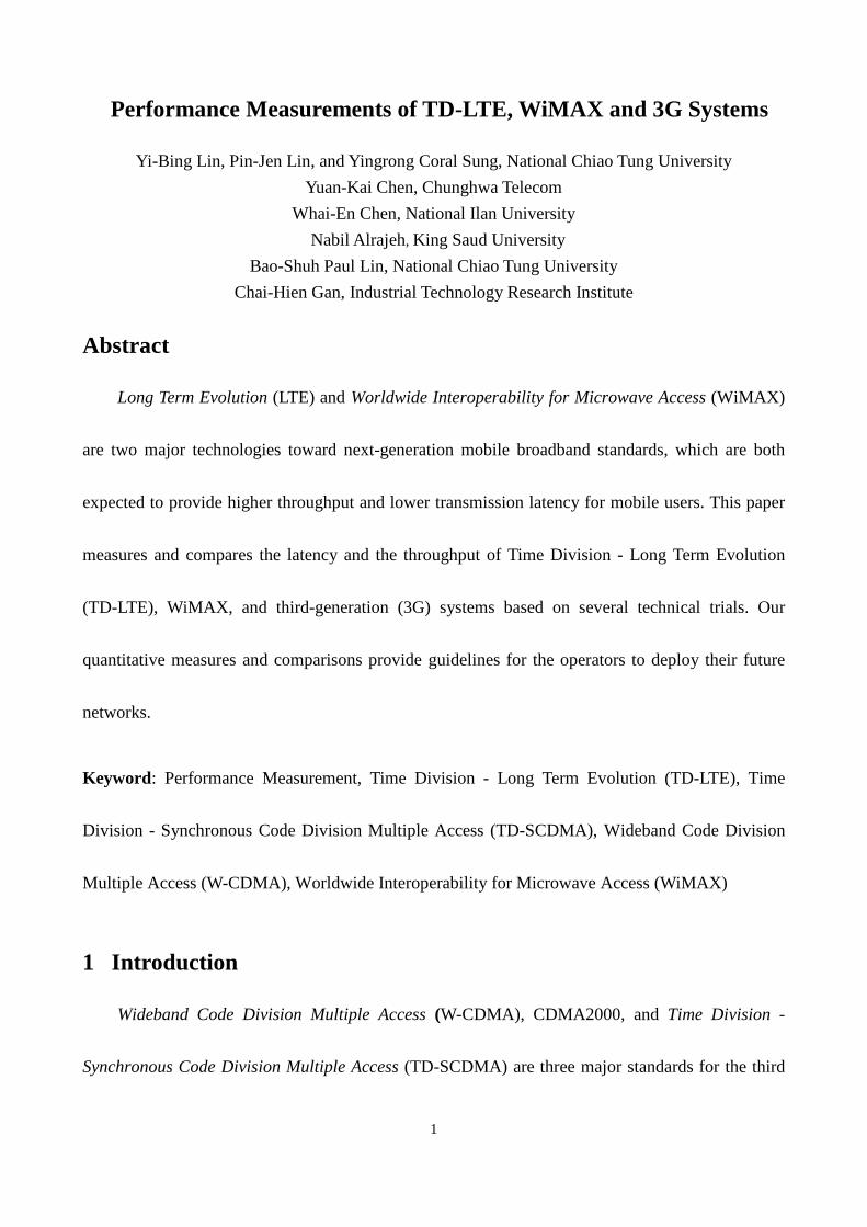
Figure 1. Test Environments of W-CDMA, TD-SCDMA, WiMAX and TD-LTE
Figure 1 introduces the test environments of W-CDMA, TD-SCDMA, WiMAX and TD-LTE.
We first illustrate the test environment of W-CDMA and TD-SCDMA. We have developed a
software tool for wireless performance measurement [6]. This performance measurement tool is
installed in notebook 1 (NB1; see Figure 1 (a)) and notebook 2 (NB2; see Figure 1 (b)), which are
connected through a 100 Mbps Ethernet link. To communicate with a Node B (the base station; see
Figure 1 (c)), NB1 is equipped with a W-CDMA (TD-SCDMA) wireless data card. The Node B
connects to the Radio Network Controller (RNC; see Figure 1 (d)) through several E1 links with the
Page 5
5
capacity larger than that at the radio layer (the capacity of one E1 link is 2.048 Mbps). The RNC
connects to the Media Gateway (MGW; see Figure 1 (e)), Serving GPRS Support Node (SGSN; see
Figure 1 (f)), and Gateway GPRS Support Node (GGSN; see Figure 1 (g)) through STM-1 links and
Gigabit Ethernet. On the other hand, NB2 connects to router 1 (Figure 1 (h)) through another 100
Mbps Ethernet link. Similarly, router 1 connects to GGSN via router 2 (Figure 1 (i)) through 100
Mbps Ethernet links. Details of RNC, MGW, SGSN, GGSN can be found in [7].When we measure
the uplink performance of W-CDMA or TD-SCDMA, the test packets are generated by NB1 and are
sent to NB2 through path (a)→(c)→(d)→(e)→(f)→(g)→(i)→(h)→(b). When NB2 receives the test
packets, it forwards the packets to NB1 through path (b)→(a). After NB1 has received the packets it
sent out, it computes the latency and packet loss performance. When we measure the downlink
performance, the test packets are generated by NB2 and sent to NB1 through the reverse path
(b)→(h)→(i)→(g)→(f)→(e)→(d)→(c)→(a)→(b). Note that in this environment, the test packets
are generated and received by the same notebook, which allows us to accurately measure the
one-way delay without time synchronization of the sender and the receiver. We have also confirmed
that the delays produced by routers 1 and 2 are less than 1 ms, and can be negligible as compared
with the total delay.
In the WiMAX test environment, NB3 (Figure 1 (j)) sends packets to NB4 (Figure 1 (k)). NB3
is equipped with a WiMAX wireless data card to communicate with the WiMAX Base Station (BS;
see Figure 1 (l)). The BS connects to the Access Service Network Gateway (ASN GW; see Figure 1
(m)), the Foreign Agent (FA; see Figure 1 (n)) and the Home Agent (HA; see Figure 1 (o)) through
Page 6
6
100 Mbps Ethernet links. Similarly, NB4 connects to HA through router 1 (Figure 1 (h)) using 100
Mbps Ethernet links. The packet delivery procedure in the WiMAX test environment is similar to
that in the W-CDMA/TD-SCDMA test environment, and the details are omitted.
In the TD-LTE test environement, the LTE core network includes System Architecture
Evolution (SAE) gateway (Figure 1 (p)), Mobility Management Entity (MME; see Figure 1 (q)) and
Home Subscriber Server (HSS; see Figure 1 (r)). The SAE gateway consists of Serving Gateway
(SGW) and Packet Data Network Gateway (PDN GW). The SGW handles inter-enhanced Node B
(eNB; see Figure 1 (s)) handover, and is responsible for routing user data packets. The PDN GW
provides connectivity between the user equipment and external data packet networks. The MME is
responsible for user authentication, bearer management, and monitoring idle UEs. The HSS is a
central database that contains user information, which also connects to SGSN and provides user
information for 3G systems. In this environment NB5 (Figure 1 (t)) sends packets to NB6 (Figure 1
(u)). NB5 is equipped with a TD-LTE data card to communicate with the eNB. The eNB connects
to the SAE, and the SAE GW connects to NB6 through 50 Mbps Ethernet links. When we measure
the uplink performance of TD-LTE, the test packets are delivered through path
(t)→(s)→(p)→(u)→(t). For downlink performance, the test packets are delivered through the
reverse path.
Page 7
7
3 Performance Measurement
This section describes performance measurement of W-CDMA, TD-SCDMA, WiMAX and
TD-LTE based on the latency and throughput of user datagram protocol (UDP) and transmission
control protocol (TCP) packets. To ensure that the four systems to be evaluated are under the same
“controlled” conditions, all measurements are conducted in indoor line-of-sight environments. The
detailed configurations for each system are described as follows. In the W-CDMA test, the HSUPA
category of the device is 3 (supports 1.46 Mbps uplink data rate), and the HSDPA category of the
device is 8 (supports 7.2 Mbps downlink data rate). In our TD-SCDMA environment, the frequency
bandwidth is 1.6 MHz and the ratio of uplink/downlink timeslots is set to 2:4, where the theoretical
uplink/downlink rates are 384 Kbps and 2.2 Mbps, respectively. In the WiMAX test, the frequency
bandwidth is 5 MHz and the uplink/downlink ratio is 2:3. A computation method was proposed in
[8] to calculate the WiMAX data rates, where the maximum downlink data rate for 5 MHz
bandwidth is 10.32 Mbps, and the maximum uplink data rate is 2.7 Mbps. In the TD-LTE test, the
subframe configurartion is set to 1 (uplink/downlink ratio 2:3) for fair comparison with WiMAX.
For LTE UE category 3 and the frequency bandwidth of 20 MHz, the theoretical maximum uplink
throughput TU is:
TU =Br× Rb × fU × �F (1)
where Br is the number of bits that a resource block (RB) can transmit within a subframe. An RB
includes 12 subcarriers in frequency domain and 14 symbols in time domain. Among the 14
symbols, 12 symbols are used for data transmission (2 symbols are used as reference signals).
Page 8
8
Assume that the modulation is 16-Quadrature Amplitude Modulation (16-QAM) and the coding rate
is 3/4 (i.e., best case), then Br = 12 × 12 × 4 × 3/4 = 432 bits. Parameter Rb is the number of RBs
used for data transmission within a subframe. For 20 MHz frequency bandwidth, Rb = 95. Parameter
fU is the number of subframes used for uplink transmission within a frame. In TD-LTE, each 10 ms
frame is divided into 10 subframes of 1 ms, and the number of subframes used for uplink
transmission depends on the subframe configuration. In subframe configuration 1, there are four
subframes used for uplink transmission and thus fU = 4. Parameter λF is the rate of frames per
second. Each frame spans 10 ms and λF = 100 frames per second. Therefore, from (1), TU = 16.4
Mbps. Similarly, the maximum downlink throughput TD is:
TD = min (Bc, Br·Rb) ×fD × �F (2)
where Bc is the maximum number of bits that a Downlink Shared Channel (DL-SCH) transport
block can receive within a subframe. For LTE category 3, Bc = 102048 bits [9]. The definitions of
Parameter Br and Rb are similar to those in (1). For TD-LTE downlink, Br∙Rb = 141960 bits (the
detailed computations are omitted), which is larger than Bc. Therefore, (2) can be simplified as:
TD = Bc ×fD × �F (3)
Parameter fD is the number of subframes that are used for downlink transmission within a
frame. In subframe configuration 1, there are 4 downlink subframes and 2 special subframes used
for downlink transmission. Therefore, when the subframe configuration is 1, fD = 4 + 2 = 6. As in
(1), λF = 100 frames per second. Therefore, from (3), we have TD = 61.2 Mbps.
Page 9
9
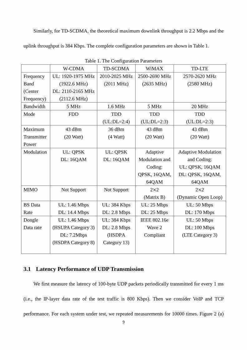
Similarly, for TD-SCDMA, the theoretical maximum downlink throughput is 2.2 Mbps and the
uplink throughput is 384 Kbps. The complete configuration parameters are shown in Table 1.
Table 1. The Configuration Parameters
W-CDMA TD-SCDMA WiMAX TD-LTE
Frequency
Band
(Center
Frequency)
UL: 1920-1975 MHz
(1922.6 MHz)
DL: 2110-2165 MHz
(2112.6 MHz)
2010-2025 MHz
(2011 MHz)
2500-2690 MHz
(2635 MHz)
2570-2620 MHz
(2580 MHz)
Bandwidth 5 MHz 1.6 MHz 5 MHz 20 MHz
Mode FDD TDD
(UL:DL=2:4)
TDD
(UL:DL=2:3)
TDD
(UL:DL=2:3)
Maximum
Transmitter
Power
43 dBm
(20 Watt)
36 dBm
(4 Watt)
43 dBm
(20 Watt)
43 dBm
(20 Watt)
Modulation UL: QPSK
DL: 16QAM
UL: QPSK
DL: 16QAM
Adaptive
Modulation and
Coding:
QPSK, 16QAM,
64QAM
Adaptive Modulation
and Coding:
UL: QPSK, 16QAM
DL: QPSK, 16QAM,
64QAM
MIMO Not Support Not Support 2×2
(Matrix B)
2×2
(Dynamic Open Loop)
BS Data
Rate
UL: 1.46 Mbps
DL: 14.4 Mbps
UL: 384 Kbps
DL: 2.8 Mbps
UL: 25 Mbps
DL: 25 Mbps
UL: 50 Mbps
DL: 170 Mbps
Dongle
Data rate
UL: 1.46 Mbps
(HSUPA Category 3)
DL: 7.2Mbps
(HSDPA Category 8)
UL: 384 Kbps
DL: 2.8 Mbps
(HSDPA
Category 13)
IEEE 802.16e
Wave 2
Compliant
UL: 50 Mbps
DL: 100 Mbps
(LTE Category 3)
3.1 Latency Performance of UDP Transmission
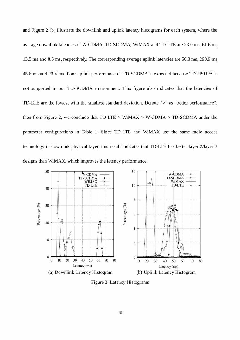
We first measure the latency of 100-byte UDP packets periodically transmitted for every 1 ms
(i.e., the IP-layer data rate of the test traffic is 800 Kbps). Then we consider VoIP and TCP
performance. For each system under test, we repeated measurements for 10000 times. Figure 2 (a)
Page 10
10
and Figure 2 (b) illustrate the downlink and uplink latency histograms for each system, where the
average downlink latencies of W-CDMA, TD-SCDMA, WiMAX and TD-LTE are 23.0 ms, 61.6 ms,
13.5 ms and 8.6 ms, respectively. The corresponding average uplink latencies are 56.8 ms, 290.9 ms,
45.6 ms and 23.4 ms. Poor uplink performance of TD-SCDMA is expected because TD-HSUPA is
not supported in our TD-SCDMA environment. This figure also indicates that the latencies of
TD-LTE are the lowest with the smallest standard deviation. Denote “>” as “better performance”,
then from Figure 2, we conclude that TD-LTE > WiMAX > W-CDMA > TD-SCDMA under the
parameter configurations in Table 1. Since TD-LTE and WiMAX use the same radio access
technology in downlink physical layer, this result indicates that TD-LTE has better layer 2/layer 3
designs than WiMAX, which improves the latency performance.
(a) Downlink Latency Histogram (b) Uplink Latency Histogram
Figure 2. Latency Histograms
Page 11
11
The above measured results are compared with the previous studies as follows. In [10], the
maximum W-CDMA downlink and uplink data rates are 384 Kbps and 64 Kbps, respectively. This
work measures the latency of UDP packets periodically transmitted every 20 ms, and the size of
packets is up to 40 bytes. The average measured downlink and uplink latencies are 108.3 ms and
101.1 ms, respectively. In [11], the latency performance of a live HSDPA enabled W-CDMA system
was measured, where the HSDPA category of the device is 12 (supports 1.8 Mbps downlink data
rate). The size of UDP packets is 105 bytes (including IP header), and the packet transmission
interval is 20 ms. In this study, the average measured downlink latencies of W-CDMA with and
without HSDPA are 50 ms and 111 ms, respectively, and the average uplink latency is 76 ms, which
are higher than our measurements. In [12], the UDP latency performance of an operational WiMAX
network was measured, which operates in the 4.9 GHz frequency band and uses 5 MHz bandwidth.
In this work, 56-byte UDP packets are periodically transmitted, and the measured downlink and
uplink latencies are 17 ms and 60 ms, respectively, which are higher (worse) than our measurement
results.
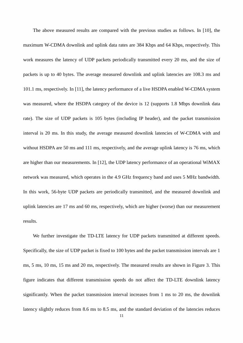
We further investigate the TD-LTE latency for UDP packets transmitted at different speeds.
Specifically, the size of UDP packet is fixed to 100 bytes and the packet transmission intervals are 1
ms, 5 ms, 10 ms, 15 ms and 20 ms, respectively. The measured results are shown in Figure 3. This
figure indicates that different transmission speeds do not affect the TD-LTE downlink latency
significantly. When the packet transmission interval increases from 1 ms to 20 ms, the downlink
latency slightly reduces from 8.6 ms to 8.5 ms, and the standard deviation of the latencies reduces
Page 12
12
from 0.8 ms to 0.6 ms. However, for TD-LTE uplink, the shorter interval (i.e., the higher
transmission speed) incurs higher latencies. When the packet transmission interval increases from 1
ms to 20 ms, the uplink latency reduces from 23.4 ms to 12.2 ms, and the standard deviations are
between 2.1 ms and 4.4 ms.
(a) Downlink Latency (b) Uplink Latency
Figure 3. TD-LTE Latency vs Packet Transmission Interval
3.2 Latency Performance of VoIP and TCP Transmissions
In this subsection, we focus on the TD-LTE latency performance of Voice over IP (VoIP) and
TCP transmissions. G.729 and G.711 codecs are selected in our VoIP tests. The size of a G.729 VoIP
packet is 50 bytes (including IP header, UDP header and RTP header), and the packet transmission
interval is 10 ms. The size of a G.711 VoIP packet is 200 bytes, and the packets are sent every 20 ms.
The maximum segment size of TCP packets is 1500 bytes (including IP header and TCP header),
and the packet transmission interval is 10 ms. The measured average downlink latencies of G.729
and G.711 VoIP packets are 8.4 ms and 8.6 ms, and the average latency of TCP data packets is 11.8
Page 13
13
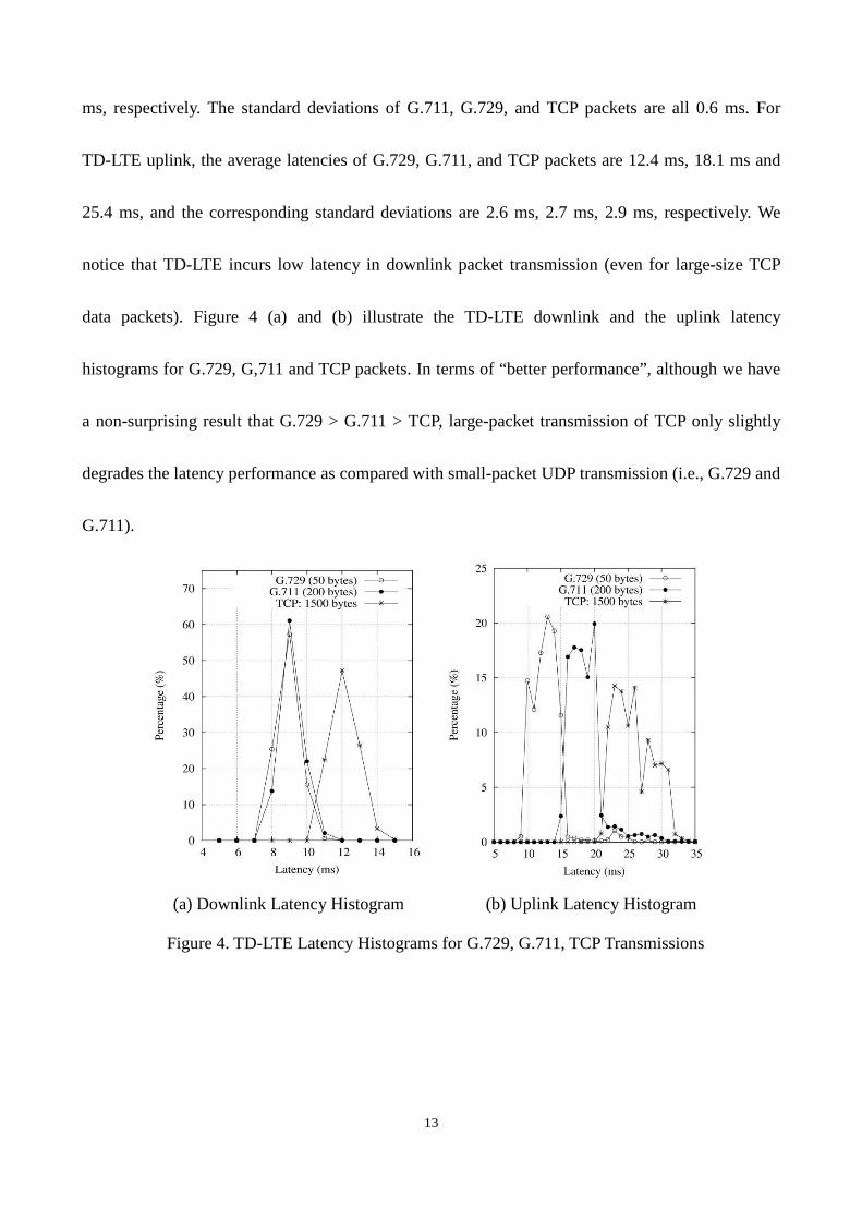
ms, respectively. The standard deviations of G.711, G.729, and TCP packets are all 0.6 ms. For
TD-LTE uplink, the average latencies of G.729, G.711, and TCP packets are 12.4 ms, 18.1 ms and
25.4 ms, and the corresponding standard deviations are 2.6 ms, 2.7 ms, 2.9 ms, respectively. We
notice that TD-LTE incurs low latency in downlink packet transmission (even for large-size TCP
data packets). Figure 4 (a) and (b) illustrate the TD-LTE downlink and the uplink latency
histograms for G.729, G,711 and TCP packets. In terms of “better performance”, although we have
a non-surprising result that G.729 > G.711 > TCP, large-packet transmission of TCP only slightly
degrades the latency performance as compared with small-packet UDP transmission (i.e., G.729 and
G.711).
(a) Downlink Latency Histogram (b) Uplink Latency Histogram
Figure 4. TD-LTE Latency Histograms for G.729, G.711, TCP Transmissions
Page 14
14
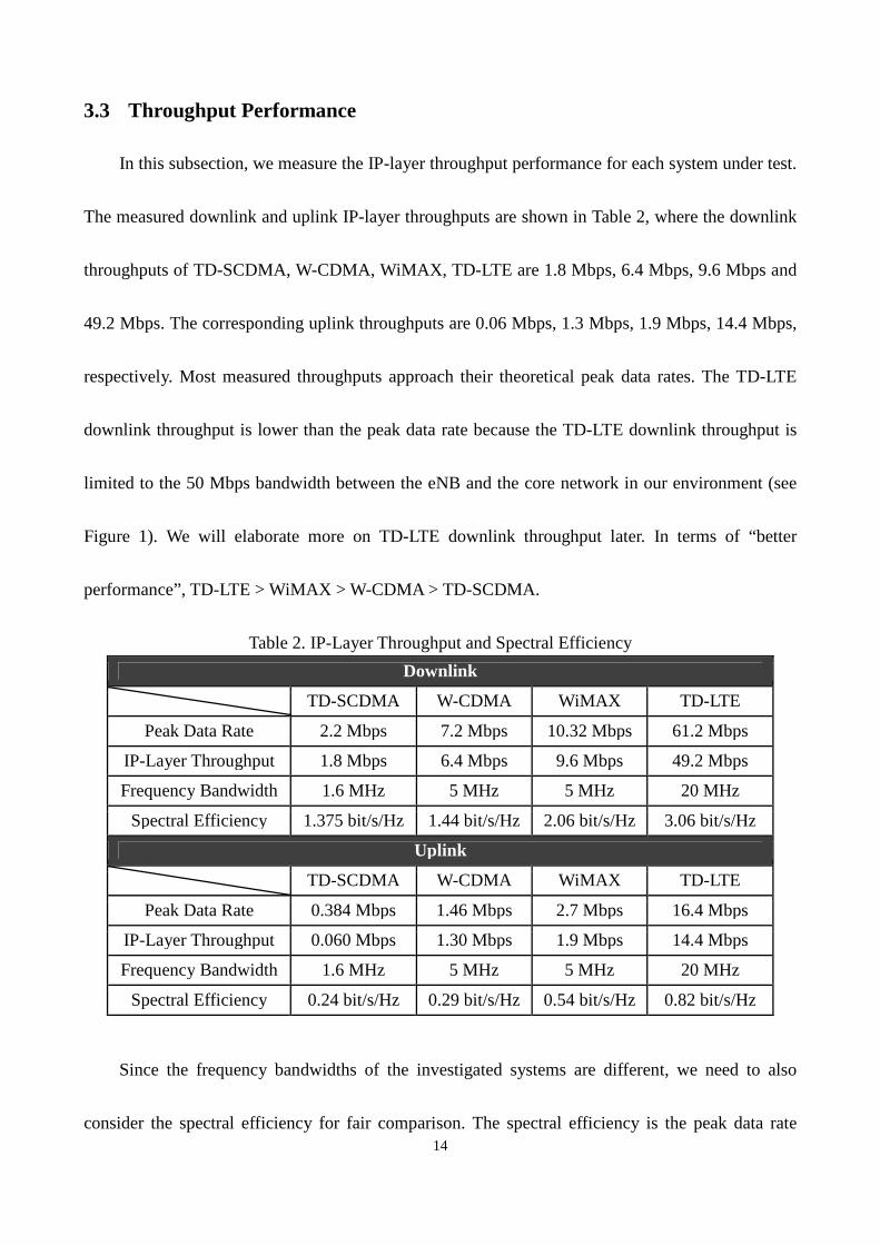
3.3 Throughput Performance
In this subsection, we measure the IP-layer throughput performance for each system under test.
The measured downlink and uplink IP-layer throughputs are shown in Table 2, where the downlink
throughputs of TD-SCDMA, W-CDMA, WiMAX, TD-LTE are 1.8 Mbps, 6.4 Mbps, 9.6 Mbps and
49.2 Mbps. The corresponding uplink throughputs are 0.06 Mbps, 1.3 Mbps, 1.9 Mbps, 14.4 Mbps,
respectively. Most measured throughputs approach their theoretical peak data rates. The TD-LTE
downlink throughput is lower than the peak data rate because the TD-LTE downlink throughput is
limited to the 50 Mbps bandwidth between the eNB and the core network in our environment (see
Figure 1). We will elaborate more on TD-LTE downlink throughput later. In terms of “better
performance”, TD-LTE > WiMAX > W-CDMA > TD-SCDMA.
Table 2. IP-Layer Throughput and Spectral Efficiency
Downlink
TD-SCDMA W-CDMA WiMAX TD-LTE
Peak Data Rate 2.2 Mbps 7.2 Mbps 10.32 Mbps 61.2 Mbps
IP-Layer Throughput 1.8 Mbps 6.4 Mbps 9.6 Mbps 49.2 Mbps
Frequency Bandwidth 1.6 MHz 5 MHz 5 MHz 20 MHz
Spectral Efficiency 1.375 bit/s/Hz 1.44 bit/s/Hz 2.06 bit/s/Hz 3.06 bit/s/Hz
Uplink
TD-SCDMA W-CDMA WiMAX TD-LTE
Peak Data Rate 0.384 Mbps 1.46 Mbps 2.7 Mbps 16.4 Mbps
IP-Layer Throughput 0.060 Mbps 1.30 Mbps 1.9 Mbps 14.4 Mbps
Frequency Bandwidth 1.6 MHz 5 MHz 5 MHz 20 MHz
Spectral Efficiency 0.24 bit/s/Hz 0.29 bit/s/Hz 0.54 bit/s/Hz 0.82 bit/s/Hz
Since the frequency bandwidths of the investigated systems are different, we need to also
consider the spectral efficiency for fair comparison. The spectral efficiency is the peak data rate
Page 15
15
divided by the frequency bandwidth. The spectral efficiency of each system is listed in Table 2,
which indicates that TD-SCDMA and W-CDMA have similar downlink spectral efficiency (a bit
less than 1.5 bit/s/Hz) and similar uplink spectral efficiency (a bit less than 0.3 bit/s/Hz). This table
also indicates that WiMAX and TD-LTE have higher spectral efficiencies than TD-SCDMA and
W-CDMA. This is a non-surprising result because WiMAX and TD-LTE support 64-QAM
modulation, while TD-SCDMA and W-CDMA only support 16-QAM modulation. On the other
hand, the downlink and uplink spectral efficiencies of TD-LTE are both higher than those of
WiMAX under the same uplink/downlink ratio. Therefore, we have a result that TD-LTE > WiMAX
> W-CDMA > TD-SCDMA, and TD-LTE has the best spectral efficiency.
We further investigate the TD-LTE throughputs measured by Nokia Siemens Network in
Hangzhou, China. In the Hangzhou test environment, the bandwidth between eNB and the core
network is sufficient and does not become the bottleneck. The measured downlink throughputs in
Hangzhou can reach 59.1 Mbps, which is consistent with the theoretical peak data rate 61.2 Mbps.
We also investigate the TD-LTE throughputs for subframe configuration 2 (uplink/downlink ratio
1:4). For subframe configuration 2, the TD-LTE uplink throughput can reach 7.3 Mbps and the
downlink throughput can reach 79.8 Mbps in the Hangzhou test environment.
4. Conclusion
In this paper, we conducted the latency and the throughput measurements of W-CDMA,
TD-SCDMA, WiMAX and TD-LTE based on several technical trials. Denote “>” as better latency
Page 16
16
and throughput performance, the measurement results indicate that TD-LTE > WiMAX > W-CDMA
> TD-SCDMA. Our quantitative measures and comparisons provide guidelines for the operators to
deploy their future networks. Clearly, migrating 3G to LTE will significantly improve the latency
and the throughput performance of an operator’s network. In the early stage of migration, LTE
could be deployed in the city areas to provide higher data rates. On the other hand, the 3G systems
will still play a role to provide service coverage during the migration.
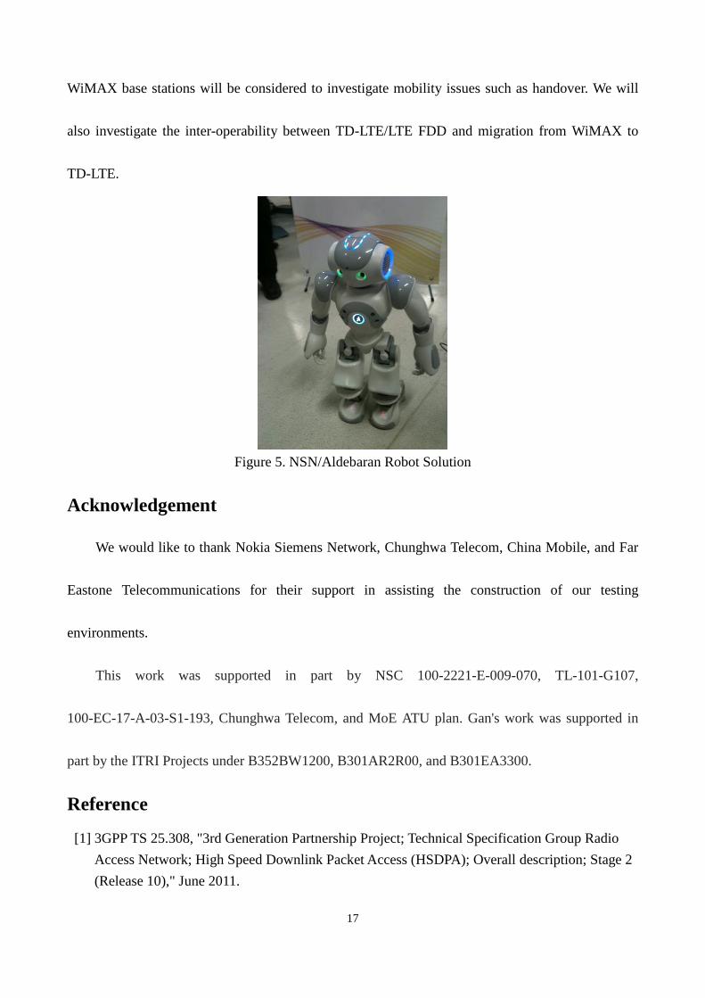
For specific applications such as remote healthcare, it is essential to utilize broadband wireless
communications between the users and the healthcare center [13]. In particular, we intend to
implement a robot application to watch aging resident at home. In this scenario, the command must
be issued from the healthcare center using wireless downlink with short and low-variance delays.
Figure 2 (a) indicates that TD-LTE satisfies this requirement the best among the four wireless
technologies. Also, the robot monitors the aging persons with high-definition video camera, and the
video will be sent back to the healthcare center with real-time wireless uplink. Again, Figure 2 (b)
suggests that TD-LTE is the best solution. Currently, we are developing the healthcare robot
applications controlled by TD-LTE based on the NSN/Aldebaran solution (see Figure 5).
This work targets on time-to-value impact within 3-5 years to assist network planning of
mobile telecom operators who are developing LTE network. Our work can also serve as a tutorial to
guide researchers to measure and test future features of LTE. Specifically, we are currently
extending our work for video/streaming, circuit switched (CS) fallback, and single radio voice call
continuity (SRVCC) measurement/testing for LTE. In our future work, multiple TD-LTE and
Page 17
17
WiMAX base stations will be considered to investigate mobility issues such as handover. We will
also investigate the inter-operability between TD-LTE/LTE FDD and migration from WiMAX to
TD-LTE.
Figure 5. NSN/Aldebaran Robot Solution
Acknowledgement
We would like to thank Nokia Siemens Network, Chunghwa Telecom, China Mobile, and Far
Eastone Telecommunications for their support in assisting the construction of our testing
environments.
This work was supported in part by NSC 100-2221-E-009-070, TL-101-G107,
100-EC-17-A-03-S1-193, Chunghwa Telecom, and MoE ATU plan. Gan's work was supported in
part by the ITRI Projects under B352BW1200, B301AR2R00, and B301EA3300.
Reference
[1] 3GPP TS 25.308, "3rd Generation Partnership Project; Technical Specification Group Radio
Access Network; High Speed Downlink Packet Access (HSDPA); Overall description; Stage 2
(Release 10)," June 2011.
Page 18
18
[2] 3GPP TS 25.309, "3rd Generation Partnership Project; Technical Specification Group Radio
Access Network; FDD Enhanced Uplink; Overall description; Stage 2 (Release 6)," March
2006.
[3] IEEE 802.16m-2011, "IEEE Standard for Local and metropolitan area networks Part 16: Air
Interface for Broadband Wireless Access Systems," May 2011.
[4] ITU-R M.2133, "Requirements, evaluation criteria and submission templates for the
development of IMT-Advanced," November 2008.
[5] Y.-B. Lin, Y.-C. Sung, H.F. Rashvand, C.-L. Liu, and Y.-J. Liao, "Mobile-Taiwan experience in
voice over IP-worldwide interoperability for microwave access trial," IET Proceedings on
Communications, vol. 4, no. 9, pp. 1130-1141, June 2010.
[6] Y.-C. Sung, Y.-B. Lin, R.-H. Liou, and L.-F. Shieh, "NCTU-VT: A Freeware for Wireless VoIP
Performance Measurement," Wireless Communications and Mobile Computing, May 2010.
[7] Y.-B. Lin and A.-C. Pang, "Wireless and Mobile All-IP Networks". Newyork: Wiley, 2005.
[8] Daan Pareit et al., "A Throughput Analysis at the MAC Layer of Mobile WiMAX," Wireless
Communications and Networking Conference (WCNC), April 2010.
[9] 3GPP TS 36.306, "3rd Generation Partnership Project; Technical Specification Group Radio
Access Network; Evolved Universal Terrestrial Radio Access (E-UTRA); User Equipment
(UE) radio access capabilities (Release 10)," September 2011.
[10] Jose Manuel Cano-Garcia, Eva Gonzalez-Parada, and Eduardo Casilari, "Experimental
Analysis and Characterization of Packet Delay in UMTS Networks," Next Generation
Teletraffic and Wired/Wireless Advanced Networking (NEW2AN), 2006.
[11] Jarmo Prokkola, Mikko Hanski, Marko Jurvansuu, and Milla Immonen, "Measuring WCDMA
and HSDPA Delay Characteristics with QoSMeT," IEEE International Conference on
Communications (ICC), June 2007.
[12] James M. Westall and James J. Martin, "Performance Characteristics of an Oprational WiMAX
Network," IEEE Transactions on Mobile Computing, vol. 10, no. 7, pp. 941-953, July 2011.
[13] Y.-B. Lin and N. Alrajeh, "Mobile Telecommunications and Applications to Healthcare
Network," Speech at King Abdulaziz City for Science and Technology, Kingdom of Saudi
Arabia, 2012.


![IEEE 802.16: WiMAX Overview, WiMAX · PDF filevs. 3G. The common Misconceptions about WiMAX & 3G CDMA are [5]: 1) Cost . c. ... IEEE 802.16: WiMAX Overview, WiMAX Architecture . Mojtaba](https://static.documents.pub/doc/80x56/5a752f217f8b9ad22a8c6f07/ieee-80216-wimax-overview-wimax-architecture-vs-3g-the-common-misconceptions.jpg)


