Reprinted from August 1988, Vol. 110, Journal of Solar Energy En g ineering Performance of a Solar Desiccant Cooling System 1 George O. G. Lof Gerald Cler Thomas Brisbane Colorado State University, Fort Collins, CO 80523 A solar desiccant cooling system was operated at the Solar Energy Applications Laboratory, Colorado State University, throughout the 1986 summer. The system comprises an American Solar King fresh air heating/ desiccant evaporative cooling unit, a Sunmaster evacuated tube solar collector, hot water solar storage tank, aux- iliary electric boiler, controls, and accessories. The cooling unit is operated in the ventilation mode, fresh air being dried in a rotating desiccant matrix, and cooled by heat exchange and evaporative cooling. Return air is used as a cooling medium in a rotating heat exchange matrix, heated by solar energy in a heat exchange coil, and discarded through the rotating desiccant bed. The solar-driven system provided over 90 percent of the seasonal cooling requirements in an experimental, residence type building at average COP levels of 1.0 and solar collection efficiencies of 50 percent when supplied with solar heated water at temperatures of 50 to 65°C. Detailed operating results, including total and average solar cooling provided, coefficients of performance, and overall solar cooling performance ratios are presented. Introduction Most of the solar cooling systems that have been built and operated are based on the supply of solar heat to absorption chillers employing the lithium bromide-water cycle [1]-[2]. Research and development on complete systems have been performed at several institutions in the United States, and several hundred operating systems have been installed in residences and commercial buildings. Absorption chillers designed specifically for operating with solar heated water at temperatures usually between 80 and l00°C have been pro- duced in limited volume by several companies, but commercial production in the U.S. is not currently active. Space cooling by use of air dehumidification followed by evaporative cooling is an alternative air conditioning process. Air dehumidification by use of a solid desiccant such as silica gel [3], molecular sieve [4], or a hygroscopic salt such as lithium chloride [5] results in the delivery of hot, dry air, the heat of absorption causing the air temperature to increase. That air can be subsequently cooled by heat exchange and an additional process such as evaporative cooling. The moisture transferred to the desiccant can be removed by desorption and evaporation into a stream of heated air and discharged to the atmosphere, thereby making the process continuous. Air dryers of the desiccant type have been commercially available for many years [6]-[7]. Theoretical analyses of air cooling systems involving desiccant and evaporative cooling processes have been made [8] and solar-driven prototypes have been developed [9]-[10] . A comprehensive review and bibliography of solid desiccant technology and air cooling processes has recently been published [11]. 1 This paper was presented at the ASME/ JSES Solar Energy Conference at Honolulu, HI, in March, 1987. Contributed by the Solar Energy Division for publication in the JOUR N AL OF SOLAR ENERGY ENGINEERING. Manuscript received by the Solar Energy Division, July, 1987; final revision, February, 1988 . Journal of Solar Energy Engineering An integrated system for dehumidifying and cooling fresh air by means of solar heated water has recently been placed in limited production for residential applications [12]-[13]. Temperature requirements for regenerating the solid desiccant are in the 50-70 °C range, thereby facilitating the use of solar heat from conventional flat plate or evacuated tube collectors. The performance of a 10.5 kW (3 ton) desiccant cooling unit operated with hot water from an electric boiler was experimen- tally measured and recently reported [14]. The purpose of the research reported in this paper is the procurement of continuous operating data on a solar desiccant cooling system assembled from commercially available com- ponents and the determination of daily and long-term cooling performance coefficients. Equipment At the Solar Energy Applications Laboratory of Colorado State University, one of several residential type buildings has been provided with a solar heating and cooling system employ- ing an Energymaster model SA-1 desiccant cooling/ fresh air heating unit manufactured by American Solar King, Inc., (now ASK Corp.), a 25.7 m 2 model TRS-81 evacuated tube solar collector manufactured by Sunmaster, Inc., 4m 3 hot water storage tank, auxiliary electric heat supply, an automatic control system, various accessories, and an exten- sive computerized monitoring system. Specifications for the principal components are listed in Table 1. A schematic representation of the system is shown in Fig. 1 and an opera- tional diagram of the cooling unit with psychrometric chart is shown in Fig. 2. Equipment Operation The Energymaster unit is provided with two water-to-air heat transfer coils, one for space heating and one for regenera- AUGUST1988, Vol.110/165
Transcript
Reprinted from August 1988, Vol. 110, Journal of Solar Energy Engineering
Performance of a Solar Desiccant Cooling System 1
George O. G. Lof
Gerald Cler
Thomas Brisbane Colorado State University,
Fort Collins, CO 80523
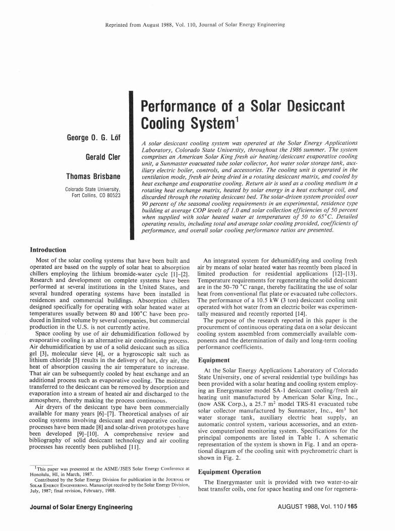
A solar desiccant cooling system was operated at the Solar Energy Applications Laboratory, Colorado State University, throughout the 1986 summer. The system comprises an American Solar King fresh air heating/ desiccant evaporative cooling unit, a Sunmaster evacuated tube solar collector, hot water solar storage tank, aux-iliary electric boiler, controls, and accessories. The cooling unit is operated in the ventilation mode, fresh air being dried in a rotating desiccant matrix, and cooled by heat exchange and evaporative cooling. Return air is used as a cooling medium in a rotating heat exchange matrix, heated by solar energy in a heat exchange coil, and discarded through the rotating desiccant bed. The solar-driven system provided over 90 percent of the seasonal cooling requirements in an experimental, residence type building at average COP levels of 1.0 and solar collection efficiencies of 50 percent when supplied with solar heated water at temperatures of 50 to 65°C. Detailed operating results, including total and average solar cooling provided, coefficients of performance, and overall solar cooling performance ratios are presented.
Introduction Most of the solar cooling systems that have been built and
operated are based on the supply of solar heat to absorption chillers employing the lithium bromide-water cycle [1]-[2]. Research and development on complete systems have been performed at several institutions in the United States, and several hundred operating systems have been installed in residences and commercial buildings. Absorption chillers designed specifically for operating with solar heated water at temperatures usually between 80 and l00°C have been pro-duced in limited volume by several companies, but commercial production in the U.S. is not currently active.
Space cooling by use of air dehumidification followed by evaporative cooling is an alternative air conditioning process. Air dehumidification by use of a solid desiccant such as silica gel [3], molecular sieve [4], or a hygroscopic salt such as lithium chloride [5] results in the delivery of hot, dry air, the heat of absorption causing the air temperature to increase. That air can be subsequently cooled by heat exchange and an additional process such as evaporative cooling. The moisture transferred to the desiccant can be removed by desorption and evaporation into a stream of heated air and discharged to the atmosphere, thereby making the process continuous.
Air dryers of the desiccant type have been commercially available for many years [6]-[7]. Theoretical analyses of air cooling systems involving desiccant and evaporative cooling processes have been made [8] and solar-driven prototypes have been developed [9]-[10] . A comprehensive review and bibliography of solid desiccant technology and air cooling processes has recently been published [11].
1 This paper was presented at the ASME/ JSES Solar Energy Conference at Honolulu, HI, in March, 1987.
Contributed by the Solar Energy Division for publication in the JOURNAL OF SOLAR ENERGY ENGINEERING. Manuscript received by the Solar Energy Division, July, 1987; final revision, February, 1988 .
Journal of Solar Energy Engineering
An integrated system for dehumidifying and cooling fresh air by means of solar heated water has recently been placed in limited production for residential applications [12]-[13]. Temperature requirements for regenerating the solid desiccant are in the 50-70 °C range, thereby facilitating the use of solar heat from conventional flat plate or evacuated tube collectors. The performance of a 10.5 kW (3 ton) desiccant cooling unit operated with hot water from an electric boiler was experimen-tally measured and recently reported [14].
The purpose of the research reported in this paper is the procurement of continuous operating data on a solar desiccant cooling system assembled from commercially available com-ponents and the determination of daily and long-term cooling performance coefficients.
Equipment At the Solar Energy Applications Laboratory of Colorado
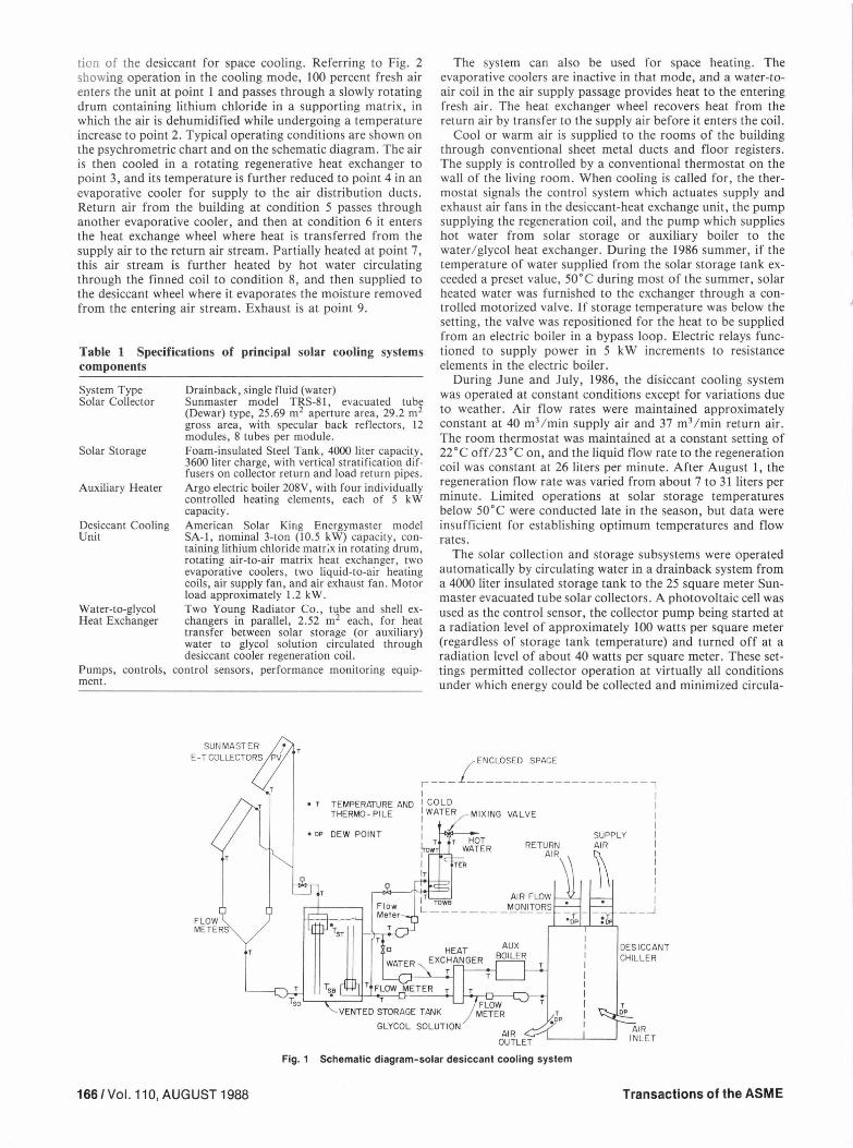
State University, one of several residential type buildings has been provided with a solar heating and cooling system employ-ing an Energymaster model SA-1 desiccant cooling/ fresh air heating unit manufactured by American Solar King, Inc., (now ASK Corp.), a 25.7 m2 model TRS-81 evacuated tube solar collector manufactured by Sunmaster, Inc., 4m 3 hot water storage tank, auxiliary electric heat supply, an automatic control system, various accessories, and an exten-sive computerized monitoring system. Specifications for the principal components are listed in Table 1. A schematic representation of the system is shown in Fig. 1 and an opera-tional diagram of the cooling unit with psychrometric chart is shown in Fig. 2.
Equipment Operation The Energymaster unit is provided with two water-to-air
heat transfer coils, one for space heating and one for regenera-
AUGUST1988, Vol.110/165
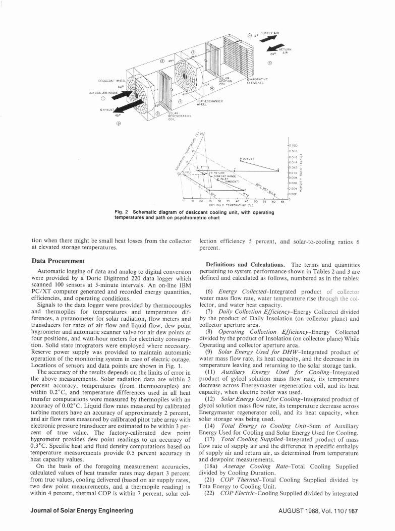
tion of the desiccant for space cooling. Referring to Fig. 2 showing operation in the cooling mode, 100 percent fresh air enters the unit at point 1 and passes through a slowly rotating drum containing lithium chloride in a supporting matrix, in which the air is dehumidified while undergoing a temperature increase to point 2. Typical operating conditions are shown on the psychrometric chart and on the schematic diagram. The air is then cooled in a rotating regenerative heat exchanger to point 3, and its temperature is further reduced to point 4 in an evaporative cooler for supply to the air distribution ducts. Return air from the building at condition 5 passes through another evaporative cooler, and then at condition 6 it enters the heat exchange wheel where heat is transferred from the supply air to the return air stream. Partially heated at point 7, this air stream is further heated by hot water circulating through the finned coil to condition 8, and then supplied to the desiccant wheel where it evaporates the moisture removed from the entering air stream. Exhaust is at point 9.
Table I Specifications of principal solar cooling systems components
System Type Solar Collector
Solar Storage
Auxiliary Heater
Desiccant Cooling Unit
Water-to-glycol Heat Exchanger
Pumps, controls, ment.
Drainback, single fluid (water) Sunmaster model TRS-81, evacuated tube (Dewar) type, 25.69 m2 aperture area, 29.2 m2
gross area, with specular back reflectors, 12 modules, 8 tubes per module. Foam-insulated Steel Tank, 4000 liter capacity, 3600 liter charge, with vertical stratification dif-fusers on collector return and load return pipes. Argo electric boiler 208V, with four individually controlled heating elements, each of 5 kW capacity. American Solar King Energymaster model SA-I, nominal 3-ton (10.5 kW) capacity, con-taining lithium chloride matr;x in rotating drum, rotating air-to-air matrix heat exchanger, two evaporative coolers, two liquid-to-air heating coils, air supply fan, and air exhaust fan. Motor load approximately 1.2 kW. Two Young Radiator Co., tube and shell ex-changers in parallel, 2.52 m2 each, for heat transfer between solar storage (or auxiliary) water to glycol solution circulated through desiccant cooler regeneration coil.
control sensors, performance monitoring equip-
FLOW METERS
• r TEMPERATURE AND THERMO - Pl LE
•DP DEW POINT
The system can also be used for space heating . The evaporative coolers are inactive in that mode, and a water-to-air coil in the air supply passage provides heat to the entering fresh air. The heat exchanger wheel recovers heat from the return air by transfer to the supply air before it enters the coil.
Cool or warm air is supplied to the rooms of the building through conventional sheet metal ducts and floor registers. The supply is controlled by a conventional thermostat on the wall of the living room. When cooling is called for, the ther-mostat signals the control system which actuates supply and exhaust air fans in the desiccant-heat exchange unit, the pump supplying the regeneration coil, and the pump which supplies hot water from solar storage or auxiliary boiler to the water/ glycol heat exchanger. During the 1986 summer, if the temperature of water supplied from the solar storage tank ex-ceeded a preset value, 50°C during most of the summer, solar heated water was furnished to the exchanger through a con-trolled motorized valve. If storage temperature was below the setting, the valve was repositioned for the heat to be supplied from an electric boiler in a bypass loop . Electric relays func-tioned to supply power in 5 kW increments to resistance elements in the electric boiler.
During June and July, 1986, the disiccant cooling system was operated at constant conditions except for variations due to weather. Air flow rates were maintained approximately constant at 40 m3 /min supply air and 37 m3 / min return air. The room thermostat was maintained at a constant setting of 22°C off/23°C on, and the liquid flow rate to the regeneration coil was constant at 26 liters per minute. After August l, the regeneration flow rate was varied from about 7 to 31 liters per minute. Limited operations at solar storage temperatures below 50°C were conducted late in the season, but data were insufficient for establishing optimum temperatures and flow rates.
The solar collection and storage subsystems were operated automatically by circulating water in a drainback system from a 4000 liter insulated storage tank to the 25 square meter Sun-master evacuated tube solar collectors. A photovoltaic cell was used as the control sensor, the collector pump being started at a radiation level of approximately 100 watts per square meter (regardless of storage tank temperature) and turned off at a radiation level of about 40 watts per square meter. These set-tings permitted collector operation at virtually all conditions under which energy could be collected and minimized circula-
DESICCANT CHILLER
GLYCOL SOLUTION r
0 0P
AIR INLET AIR
OUTLET
Fig. 1 Schematic diagram- solar desiccant cooling system
166 /Vol. 110, AUGUST 1988 Transactions of the ASME
/"';:\ SUPPLY AIR \:!/ 12° .,,,,,,,, ~URN
23 0 AL R
®
®
0020
0018
0016
0014
0 012
ooro 0008
0006
0 004
0002
•• Fig. 2 Schematic diagram of desiccant cooling unit, with operating temperatures and path on psychrometric chart
tion when there might be small heat losses from the collector at elevated storage temperatures.
Data Procurement Automatic logging of data and analog to digital conversion
were provided by a Doric Digitrend 220 data logger which scanned 100 sensors at 5-minute intervals. An on-line IBM PC/XT computer generated and recorded energy quantities, efficiencies, and operating conditions.
Signals to the data logger were provided by thermocouples and thermopiles for temperatures and temperature dif-ferences, a pyranometer for solar radiation, flow meters and transducers for rates of air flow and liquid flow, dew point hygrometer and automatic scanner valve for air dew points at four positions, and watt-hour meters for electricity consump-tion. Solid state integrators were employed where necessary. Reserve power supply was provided to maintain automatic operation of the monitoring system in case of electric outage. Locations of sensors and data points are shown in Fig. I.
The accuracy of the results depends on the limits of error in the above measurements. Solar radiation data are within 2 percent accuracy, temperatures (from thermocouples) are within 0.2°C, and temperature differences used in all heat transfer computations were measured by thermopiles with an accuracy of 0.02 °C. Liquid flow rates measured by calibrated turbine meters have an accuracy of approximately 2 percent, and air flow rates measured by calibrated pitot tube array with electronic pressure transducer are estimated to be within 3 per-cent of true value. The factory-calibrated dew point hygrometer provides dew point readings to an accuracy of 0.3 °C. Specific heat and fluid density computations based on temperature measurements provide 0.5 percent accuracy in heat capacity values.
On the basis of the foregoing measurement accuracies, calculated values of heat transfer rates may depart 3 percent from true values, cooling delivered (based on air supply rates, two dew point measurements, and a thermopile reading) is within 4 percent, thermal COP is within 7 percent, solar col-
Journal of Solar Energy Engineering
lection efficiency 5 percent, and solar-to-cooling ratios 6 percent.
Definitions and Calculations. The terms and quant1t1es pertaining to system performance shown in Tables 2 and 3 are defined and calculated as follows, numbered as in the tables:
(6) Energy Collected-Integrated product of collector water mass flow rate, water temperature rise through the col-lector, and water heat capacity.
(7) Daily Collection Efficiency-Energy Collected divided by the product of Daily Insolation (on collector plane) and collector aperture area.
(8) Operating Collection Efficiency-Energy Collected divided by the product of lnsolation (on collector plane) While Operating and collector aperture area.
(9) Solar Energy Used for DHW-integrated product of water mass flow rate, its heat capacity, and the decrease in its temperature leaving and returning to the solar storage tank.
(11) Auxiliary Energy Used for Cooling-integrated product of gylcol solution mass flow rate, its temperature decrease across Energymaster regeneration coil, and its heat capacity, when electric boiler was used.
(12) Solar Energy Used for Cooling-Integrated product of glycol solution mass flow rate, its temperature decrease across Energymaster regenerator coil, and its heat capacity, when solar storage was being used .
(14) Total Energy to Cooling Unit-Sum of Auxiliary Energy Used for Cooling and Solar Energy Used for Cooling.
(17) Total Cooling Supplied-integrated product of mass flow rate of supply air and the difference in specific enthalpy of supply air and return air, as determined from temperature and dewpoint measurements .
(I Sa) Average Cooling Rate-Total Cooling Supplied divided by Cooling Duration.
(21) COP Thermal-Total Cooling Supplied divided by Tota Energy to Cooling Unit.
(22) COP Electric-Cooling Supplied divided by integrated
AUGUST 1988, Vol. 110/167
Table2 Average daily performance of solar desiccant cooling systems on seven representative days
10) Temp, Storage to Exchanger 61.4 64.1 60.1 55.3 57 .3 62.9 11) Aux Energy Used for Cooling 20.04 0 3.27 17.53 11.82 0 12) Solar Energy Used for Cooling 152.72 180.22 153.82 188.98 153.42 199.26 13) Temperature of Auxiliary 62.1 53.9 14) Total Energy to Cooling Unit 172.76 180.22 157 .09 206.51 165 .24 199.26 15) Temperature, Exchanger to Cooler 55.8 59.6 56.8 52.8 54.1 59.6 16) Liquid Rate to Cooler I/min. 26 .0 26.0 26.0 26 .0 26.0 26. 0 17) Total Cooling Supplied, MJ/ day 87.6 147.8 145 .0 211.2 164.6 196.4 18) Cooling Duration, hours/ day 5.1 7.1 7.2 I0.2 8.4 9.2 19) Temperature Supply Air 12.5 11.6 11.7 12.0 12.4 11.6 20) Temperature Return Air 20.6 20.8 21.0 21.2 21.1 20.8 21) COP Thermal 0.51 0.82 0.92 1.02 1.00 0.99 22) COP Electric 4.73 5.38 4.97 5.17 4.92 5.34 23) Cooling by Solar , fraction 0.88 1.00 0.98 0.92 0.93 1.00 24) Solar Cooling Performance Factor 0.19 0.29 0.31 0.43 0.32 0.43 25) SCPF Adjusted for Solar DHW 0.31 0.38 0.41 0.51 0.40 0.43*
• No solar energy was used for water heating during this period .
Notes for Tables 2 and 3: Temperatures are daily averages, °C. Energy quantities are MJ/ day unless otherwise specified. Insolation measured on collector tilted at 45 degrees.
total electric energy usage for operation of motors in Energymaster unit.
(23) Cooling by Solar, fraction-Solar Energy Used for Cooling divided by Total Energy to Cooling Unit.
(24) Solar Cooling Performance Factor- Product of Total Cooling Supplied and Cooling by Solar, fraction, divided by product of Daily Insolation and collector aperture area.
(25) SCPF Adjusted for Solar DBW-Product of Total Cooling Supplied and Cooling by Solar, fraction, divided by product of Daily Insolation, collector aperture area, and the fraction of collected energy used for cooling (Solar Energy to Cooling Unit divided by sum of Solar Energy to Cooling Unit and Solar Energy Use for DHW).
Results The results of monitored automatic operation of the system
168/Vol.110,AUGUST1988
each day during the summer of 1986 are summarized in Tables 2 and 3 and Figs. 3 to 5. Table 2 contains the measured condi-tions and computed performance parameters on seven representative full days. Data obtained at 5-minute intervals were averaged and integrated over hourly and daily periods. Temperatures pertaining to the cooling unit are averages of measurements during the actual periods of its operation, shown in the table. Collector delivery temperatures are averages during collector operation. Cooling operation typically occurred seven to ten hours per day, usually starting about 10:00 a.m.
Table 3 involves the same conditions and performance in-dicators as Table 2, with daily averages and totals compiled and summarized over six 10-day periods. These results can be considered representative of normal system performance, day-to-day variations having been smoothed by averaging and in-
Transactions of the ASME
9
8
• • ~ ~ ::> 6 Q.
"" ::> 0
"' 5 z
• • • • • • • • I ~·
•• • • •
~ • •I. . . ..... ... - .. \,
• • •• :::; 0 0 u WET BULB
• • • AMBIENT CONDITIONS ENT HALPY
• .. 24 .0-34.0kJ/ kg, 7.5-12 °C • 34' -39.0 kJ/kg . 12 - 14 °C
• 39 I -43.0 kJ/kg , 14 - 15.5°C • 43 I -48.0 kJ/kg , 15.5 - 17 °C
• 50 55 60 65 70
REGENERATION TEMPERATURE {°C)
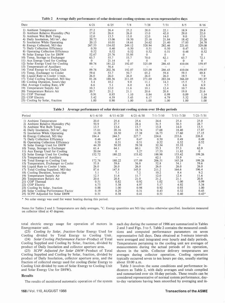
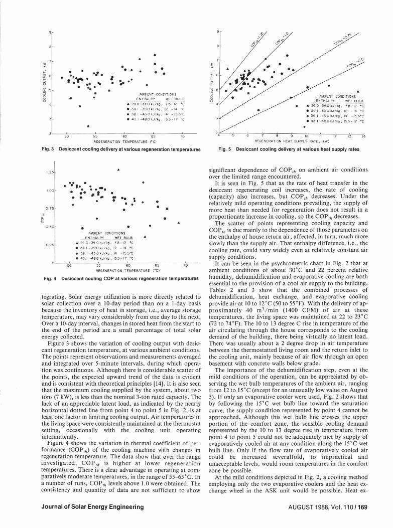
Fig. 3 Desiccant cooling delivery at various regeneration temperatures
Q. 0 u
1.25
1.00
0 . 75
0 .50
0 .25
• • • • • I• • • ••
"
~ ... • • • ~ ,_ • •• • • • • • • • •
• • •
AMBIENT CONDITIONS ENTHALPY WET BULB
.. 24 .0-34 .0kJ/kg, 7.5-12 °C • 34. 1 -39.0 kJ / kg' 12 - 14 °C e 39 . I -43.0 kJ/ k9, 14 -15 .5°C
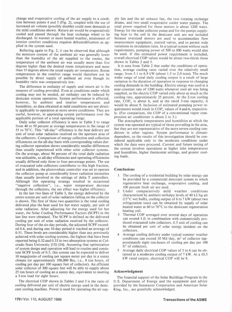
Fig. 4 Desiccant cooling COP at various regeneration temperatures
tegrating. Solar energy utilization is more directly related to solar collection over a 10-day period than on a I-day basis because the inventory of heat in storage, i.e., average storage temperature, may vary considerably from one day to the next. Over a 10-day interval, changes in stored heat from the start to the end of the period are a small percentage of total solar energy collected .
Figure 3 shows the variation of cooling output with desic-cant regeneration temperature, at various ambient conditions. The points represent observations and measurements averaged and integrated over 5-minute intervals, during which opera-tion was continuous. Although there is considerable scatter of the points, the expected upward trend of the data is evident and is consistent with theoretical principles [14]. It is also seen that the maximum cooling supplied by the system, about two tons (7 kW), is less than the nominal 3-ton rated capacity. The lack of an appreciable latent load, as indicated by the nearly horizontal dotted line from point 4 to point 5 in Fig. 2, is at least one factor in limiting cooling output. Air temperatures in the living space were consistently maintained at the thermostat setting, occasionally with the cooling unit operating intermittently.
Figure 4 shows the variation in thermal coefficient of per-formance (COP th) of the cooling machine with changes in regeneration temperature. The data show that over the range investigated, COP th is higher at lower regeneration temperatures. There is a clear advantage in operating at com-paratively moderate temperatures, in the range of 55-65 °C. In a number of runs, COP th levels above 1.0 were obtained. The consistency and quantity of data are not sufficient to show
Journal of Solar Energy Engineering
9
"" ::> 6 Q.
"" ::> 0
"' ~ 0 0 u
6
{' ·'· •'9
"'(} R'"
""' -•
•
9
• " AMBIENT CONDITIONS
ENTHALPY WET BULB • .. 24 .0-34.0kJ/kg, 7.5- 12 °C
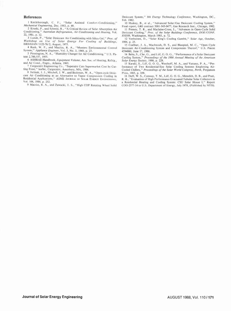
Fig. 5 Desiccant cooling delivery at various heat supply rates
significant dependence of COPth on ambient air conditions over the limited range encountered.
It is seen in Fig. 5 that as the rate of heat transfer in the desiccant regenerating coil increases , the rate of cooling (capacity) also increases, but COPth decreases. Under the relatively mild operating conditions prevailing, the supply of more heat than needed for regeneration does not result in a proportionate increase in cooling, so the COP th decreases.
The scatter of points representing cooling capacity and COP th is due mainly to the dependence of those parameters on the enthalpy of house return air , affected, in turn, much more slowly than the supply air. That enthalpy difference, i.e., the cooling rate, could vary widely even at relatively constant air supply conditions.
It can be seen in the psychrometric chart in Fig. 2 that at ambient conditions of about 30°C and 22 percent relative humidity, dehumidification and evaporative cooling are both essential to the provision of a cool air supply to the building. Tables 2 and 3 show that the combined processes of dehumidification , heat exchange, and evaporative cooling provide air at IO to 12°C (50 to 55°F). With the delivery of ap-proximately 40 m3 / min (1400 CFM) of air at these temperatures, the living space was maintained at 22 to 23 °C (72 to 74 °F). The 10 to 13 degree Crise in temperature of the air circulating through the house corresponds to the cooling demand of the building, there being virtually no latent load. There was usually about a 2 degree drop in air temperature between the thermostatted living room and the return inlet to the cooling unit , mainly because of air flow through an open basement with concrete walls below grade.
The importance of the dehumidification step, even at the mild conditions of the operation, can be appreciated by ob-serving the wet bulb temperatures of the ambient air, ranging from 12 to 15°C (except for an unusually low value on August 5) . If only an evaporative cooler were used, Fig. 2 shows that by following the 15°C wet bulb line toward the saturation curve, the supply condition represented by point 4 cannot be approached. Although this wet bulb line crosses the upper portion of the comfort zone, the sensible cooling demand represented by the 10 to 13 degree rise in temperature from point 4 to point 5 could not be adequately met by supply of evaporatively cooled air at any condition along the 15°C wet bulb line . Only if the flow rate of evaporatively cooled air could be increased severalfold, to impractical and unacceptable levels, would room temperatures in the comfort zone be possible .
At the mild conditions depicted in Fig. 2, a cooling method employing only the two evaporative coolers and the heat ex-change wheel in the ASK unit would be possible. Heat ex-
AUGUST1988, Vol.110/169
change and evaporative cooling of the air supply to a condi-tion between points 4 and 5 (Fig. 2), coupled with the use of increased air volume (possibly double) could meet demands at the mild conditions shown. Return air would be evaporatively cooled and passed through the heat exchange wheel to be discharged. In warmer or more humid weather, attainment of interior comfort conditions requires dehumidification as ap-plied in the system used.
Referring again to Fig. 2, it can be observed that although the moisture content of the ambient air was generally lower than the humidity of the air supplied to the rooms, the temperature of the ambient air was usually more than five degrees higher than the desired room temperature and more than 15 degrees above the usual supply air temperature. Room temperatures in the comfort range would therefore not be possible by direct supply of ambient air even though its humidity ratio was comparatively low.
The difference in enthalpy of supply and return air is the measure of cooling provided. Even at conditions under which cooling may not be needed, air enthalpy can be reduced by desiccant system operation. System performance is affected, however, by ambient and interior temperatures and humidities, so data obtained at mild conditions are not direct-ly applicably to operation at more severe conditions. They are useful, however, in appraising system performance over the applicable portion of a total operating range.
Daily solar collector efficiency is seen in Table 2 to range from 40 to 50 percent at storage temperatures in the range of 55 to 70°C. This "all-day" efficiency is the heat delivery per unit of total solar radiation received on the aperture area of the collectors. Comparison of energy collection and collection efficiencies on the all-day basis with corresponding values dur-ing collector operation shows considerably smaller differences than usually experienced with other solar collector systems. On the average, about 94 percent of the total daily radiation was utilizable, so all-day efficiencies and operating efficiencies usually differed only three to four percentage points . The use of evacuated tube collectors contributes to this high fraction, and in addition, the photovoltaic controller was set to operate the collector pump at considerably lower radiation intensities than usually involved in the settings of delta T controllers. Although this operating strategy resulted in occasional "negative collection", i.e., water temperature decrease through the collectors, the net effect was higher efficiency.
In the last two lines of Table 3, the energy delivered by the entire system per unit of solar radiation falling on the collector is shown. The first of these two quantities is the total cooling delivered plus the heat used for hot water supply , per unit of solar radiation. After adjusting for the energy used for hot water, the Solar Cooling Performance Factors (SCPF) in the last line were obtained. The SCPF is defined as the delivered cooling per unit of solar radiation received by the collector. During four of the six-day periods, the adjusted SCPF exceed-ed 0.4, and during one 10-day period it reached an average of 0.51. These levels are considerably higher than any previously achieved with solar cooling systems, the highest that have been reported being 0.32 and 0.33 in two absorption systems at Col-orado State University [15]-[16]. Assuming that optimization of system design and operation will lead to routine and consis-tent SCPF levels of 0.5, this system can be expected to deliver 10 megajoules of cooling per square meter per day in a sunny climate (or approximately 100,000 Btu, i.e., 8 ton hours, of cooling per day per 100 square feet of collector). An efficient solar collector of 300 square feet will be able to supply about 25 ton hours of cooling an a sunny day, equivalent to meeting a 3-ton load for eight hours.
The electrical COP shown in Tables 2 and 3 is the ratio of cooling delivered per unit of electric energy used in the desic-cant cooling machine. Power is used for operating the air sup-
170/Vol.110,AUGUST1988
ply fan and the air exhaust fan, the two rotating exchange drums, and two small evaporative cooler water pumps. The total power required for those motors is about 1200 watts. Energy for the solar collector pump and for the pumps supply-ing heat to the coil in the desiccant unit are not included because oversized motors are used to accommodate flow measurement equipment, control valves, and to permit wide variations in circulation rates. In a typical system without such requirements, pumping power of 500 to 800 watts would also be used. If this estimated power requirement is included, overall electrical COP values would be about two-thirds those shown in Tables 2 and 3.
It is seen from Table 2 that under the conditions of opera-tion, average cooling rates varied over the relatively small range, from 5.1 to 6.9 kW (about 1.5 to 2.0 tons). The much wider range of total daily cooling output is a result of large variation in the duration of operation in response to changing cooling demands in the building. Electric energy was used at a near-constant rate of 1200 watts whenever cool air was being supplied, so the electric COP varied only about as much as the cooling rate, approximately 25 percent. At the 2-ton cooling rate, COP, is about 6, and at the rated 3-ton capacity, it would be about 9. Inclusion of estimated pumping p0wer re-quirements would result in COP, values of 4 and 6, respective-ly. (For comparison, the COP of a conventional vapor com-pression air conditioner is about 2 to 3.)
The atmospheric temperatures and humidities at which the system was operated are typical of those prevailing in the area, but they are not representative of the more severe cooling con-ditions in other regions. System performance is climate-dependent, so the results of this investigation should be con-sidered applicable only to the moderate conditions under which the data were procured. Current and future testing of the system involves operations at higher inlet temperatures and humidities, higher thermostat settings, and greater cool-ing loads.
Conclusions The cooling of a residential building by solar energy can be provided by a commercial desiccant system in which regenerative heat exchange, evaporative cooling, and 100 percent fresh air are used.
2 Under comparatively mild weat her conditions characterized by ambient enthalpy levels of 40 kJ / kg air (15 °C wet bulb), cooling output of 6 to 7 kW (about two refrigeration tons) can be obtained by supply of solar heated water at 60 to 70°C to the desiccant regeneration heating coil.
3 Thermal COP averaged over several days of operation can exceed 1.0; in combination with commercially pro-duced evacuated tube collectors, 0.5 unit of cooling can be obtained per unit of solar energy incident on the collectors.
4 Average cooling delivery under typical summer weather conditions can exceed 10 MJ/ day, m2 of collector (ap-proximately eight ton-hours of cooling per day per 100 ft 2 of collector).
5 Average daily electrical COP values of 5 to 6 can be ob-tained at a moderate cooling output of 7 kW. At a 10.5 kW rated output, electrical COP will be 9.
Acknowledgment The financial support of the Solar Buildings Program in the
U.S. Department of Energy and the equipment and advice provided by the Sunmaster Corporation and American Solar King, Inc., are gratefully acknowledged .
Transactions of the ASME
References I Kettleborough, C. F., "Solar Assisted Comfort-Conditioning,"
Mechanical Engineering, Dec . 1983, p. 48 . 2 Krushi, P., and Schmid, R., "A Critical Review of Solar Absorption Air
Conditioning," Australian Refrigeration, Air Condirioning and Heating, Vol. 22, 1981, p. 12.
3 Lunde, P., "Solar Desiccant Air Conditioning with Silica Gel," Proc. of Workshop on Use of Solar Energy For Cooling of Buildings, ERDASAN/ 1122-76/2, August, 1975.
4 Rush , W. F., and Macriss, R. A ., " Munters Environmental Control System," Appliance Engineer, Vol. 3, No. 3, 1969, p. 23.
5 Pennington, N. A., " Humidity Changer for Air Conditioning," U.S. Pa-tent 2,700,537, 1955 .
6 ASH RAE Handbook, Equipment Volume, Am. Soc. of Heating, Refrig., and Air Cond ., Engrs., Atlanta, 1983.
8 Jurinak, J. J., Mitchell, J. W., and Beckman, W. A., "Open-cycle Desic-cant Air Conditioning as an Alternative to Vapor Compression Cooling in Residential Applications," ASME JOURNAL OF SOLAR ENERGY ENGINEERING, Vol. 106, 1984, p. 252.
9 Macriss, R. A., and Zawacki, T. S., "High COP Rotating Wheel Solid
IO Huskey, B., et al., "Advanced Solar/ Gas Desiccant Cooling System," Final report, GR! contract 5081-343-0477, Gas Research Inst., Chicago, 1982.
11 Penney, T. R., and Maclaine-Cross, I., "Advances in Open-Cycle Solid Desiccant Cooling," Proc. of the Solar Buildings Conference, DOE/CONF. 850388, Washington , March 1985, p. 72.
12 Venhuizen, D., "Solar King's Cooling Gambit," Solar Age, October, 1984, p. 25.
13 Coellner , J . A ., Macintosh, D. S., and Blanpied, M. C., "Open Cycle Desiccant Air-Conditioning System and Components Thereof," U.S. Patent 4594860, June 17, 1986.
14 Beba, S., Cler, G., and Lof, G. 0. G. , "Performance of a Solar Desiccant Cooling System," Proceedings of the 1986 Annual Meeting of the American Solar Energy Society, 1986, p. 228.
15 Karaki, S., LOf, G. 0. G., Westhoff, M.A., and Vattano, P. A., "Per-formance of Two Residential-Size Solar Cooling Systems Employing Air-Cooled Chillers," Proceedings of the Solar World Congress, Perth, Pergamon Press, 1983, p. 109.
16 Duff, W. S., Conway, T . M., LOf, G. 0. G., Meredith, D. B., and Pratt, R. B., "Evaluation of High Performance Evacuated Tubular Solar Collectors in a Residential Heating and Cooling System: CSU Solar House I, " Report C00-2577-14 to U.S. Department of Energy, July 1978, (Published by NTIS) .