fibers Article Performance of Hybrid Reinforced Concrete Beam Column Joint: A Critical Review Md Rashedul Kabir 1,† , M. Shahria Alam 1, * ,† , Aly M. Said 2,† and Achraf Ayad 2,† 1 School of Engineering, University of British Columbia, Kelowna, BC V1V1V7, Canada; [email protected]2 Department of Architectural Engineering, The Pennsylvania State University, University Park, PA 16802, USA; [email protected] (A.M.S.); [email protected] (A.A.) * Correspondence: [email protected]; Tel.: +1-250-807-9397; Fax: +1-250-807-9850 † These authors contributed equally to this work. Academic Editor: Mahmoud Reda Taha Received: 28 November 2015; Accepted: 28 March 2016; Published: 13 April 2016 Abstract: Large residual strain in reinforced concrete structures after a seismic event is a major concern for structural safety and serviceability. Alternative reinforcement materials like fiber-reinforced polymer (FRP) have been widely used to mitigate corrosion problems associated with steel. Low modulus of elasticity and brittle behavior compared to steel has made the use of FRP unsuitable in seismic resistant strictures. A combination of steel-FRP reinforcement configuration can address the problem of corrosion. Therefore, introducing a material that shows strong post elastic behavior without any decay due to corrosion is in demand. Shape memory alloy (SMA), a novel material, is highly corrosion resistive and shows super elastic property. Coupling SMA with FRP or steel in the plastic hinge region allows the structure to undergo large deformations, but regains its original shape upon unloading. In this study, the performance characteristics of four previously tested beam-column joints reinforced with different configurations (steel, SMA/steel, glass fiber reinforced polymer (GFRP) and SMA/FRP) are compared to assess their capacity to endure extreme loading. Experimental results are scrutinized to compare the behavior of these specimens in terms of load-story drift and energy dissipation capacity. SMA/FRP and SMA/Steel couples have been found to be an acceptable approach to reduce residual deformation in beam-column joints with adequate energy dissipation capacity. However, SMA/FRP is superior to SMA/Steel concerning to the corrosion issue in steel. Keywords: SMA; GFRP; beam-column joint; seismic 1. Introduction Corrosion and formation of rust in the steel embedded in concrete generates internal stresses and causes spalling of concrete cover. It is detrimental to the performance of structural members due to the reduction in cross-sectional area as well as undermining the steel-concrete bond and may lead to catastrophic failures. Billions of dollars are spent annually on the rehabilitation of civil infrastructure, especially to address the impact of corrosion among many issues. Furthermore, modern equipment that employ magnetic interferometers, such as in hospitals and laboratory equipment require a nonmagnetic environment. These have led to an increasing interest in fiber-reinforced polymer (FRP) reinforcement, which is inherently nonmagnetic and resistant to corrosion. Additionally, the light weight of FRP offers considerable cost savings in terms of labor and requires minimum or no maintenance cost. FRP reinforcement also provides the option of easily embedding fiber optic strain measurement devices for structural health monitoring purposes. A study by Mady et al. [1] shows that glass fiber reinforced polymer (GFRP) is promising in mitigating the linear-elastic up to failure characteristics Fibers 2016, 4, 13; doi:10.3390/fib4020013 www.mdpi.com/journal/fibers
Transcript
fibers
Article
Performance of Hybrid Reinforced Concrete BeamColumn Joint: A Critical Review
Md Rashedul Kabir 1,†, M. Shahria Alam 1,*,†, Aly M. Said 2,† and Achraf Ayad 2,†
1 School of Engineering, University of British Columbia, Kelowna, BC V1V1V7, Canada;[email protected]
2 Department of Architectural Engineering, The Pennsylvania State University, University Park, PA 16802,USA; [email protected] (A.M.S.); [email protected] (A.A.)
* Correspondence: [email protected]; Tel.: +1-250-807-9397; Fax: +1-250-807-9850† These authors contributed equally to this work.
Academic Editor: Mahmoud Reda TahaReceived: 28 November 2015; Accepted: 28 March 2016; Published: 13 April 2016
Abstract: Large residual strain in reinforced concrete structures after a seismic event is a major concernfor structural safety and serviceability. Alternative reinforcement materials like fiber-reinforcedpolymer (FRP) have been widely used to mitigate corrosion problems associated with steel.Low modulus of elasticity and brittle behavior compared to steel has made the use of FRP unsuitablein seismic resistant strictures. A combination of steel-FRP reinforcement configuration can addressthe problem of corrosion. Therefore, introducing a material that shows strong post elastic behaviorwithout any decay due to corrosion is in demand. Shape memory alloy (SMA), a novel material,is highly corrosion resistive and shows super elastic property. Coupling SMA with FRP or steel inthe plastic hinge region allows the structure to undergo large deformations, but regains its originalshape upon unloading. In this study, the performance characteristics of four previously testedbeam-column joints reinforced with different configurations (steel, SMA/steel, glass fiber reinforcedpolymer (GFRP) and SMA/FRP) are compared to assess their capacity to endure extreme loading.Experimental results are scrutinized to compare the behavior of these specimens in terms of load-storydrift and energy dissipation capacity. SMA/FRP and SMA/Steel couples have been found to be anacceptable approach to reduce residual deformation in beam-column joints with adequate energydissipation capacity. However, SMA/FRP is superior to SMA/Steel concerning to the corrosion issuein steel.
Keywords: SMA; GFRP; beam-column joint; seismic
1. Introduction
Corrosion and formation of rust in the steel embedded in concrete generates internal stresses andcauses spalling of concrete cover. It is detrimental to the performance of structural members due tothe reduction in cross-sectional area as well as undermining the steel-concrete bond and may lead tocatastrophic failures. Billions of dollars are spent annually on the rehabilitation of civil infrastructure,especially to address the impact of corrosion among many issues. Furthermore, modern equipment thatemploy magnetic interferometers, such as in hospitals and laboratory equipment require a nonmagneticenvironment. These have led to an increasing interest in fiber-reinforced polymer (FRP) reinforcement,which is inherently nonmagnetic and resistant to corrosion. Additionally, the light weight of FRPoffers considerable cost savings in terms of labor and requires minimum or no maintenance cost.FRP reinforcement also provides the option of easily embedding fiber optic strain measurementdevices for structural health monitoring purposes. A study by Mady et al. [1] shows that glass fiberreinforced polymer (GFRP) is promising in mitigating the linear-elastic up to failure characteristics
of FRP where it satisfied both strength and deformation requirements without slippage of the beambars. Other studies [2] has shown that circular column reinforced with GFRP bars and spirals behavein a similar manner to steel RC columns in a ductile manner. Furthermore, joints in GFRP reinforcedmoment connections can sustain joint shear stress level up to 0.85
a
f 1c [3]. Hawileh et al. [4,5]
investigated finite element modeling of structures reinforced with aramid fiber reinforced polymer(AFRP) and steel in a hybrid configuration. Modeling showed that hybrid configuration can be used toprovide a balance between strength and ductility while providing superior corrosion protection.
Nonetheless, FRP materials often exhibit lower ductility and weaker bond to concrete comparedto that of conventional steel reinforcement. Typically, the bond performance between FRP andsurrounding concrete can be improved by means of mechanical anchorages such as surfacedeformations and sand coating. During strong ground motion and dynamic loading, the lowerductility of FRP still is a major concern. Brown and Bartholomew [6] showed that steel reinforced andFRP reinforced beam behave similarly in terms of section mechanics. Steel reinforced concrete strengthdesign method is applicable to that of FRP reinforced beam to find the ultimate moment capacity.However, deflection and ductility criteria govern the design process for FRP reinforcement, whichis not the case for steel reinforcement. Lower ductility of FRP remains a major concern especially instructures subjected to dynamic loading. FRP fails within its elastic range with low energy dissipationcapacity, which is considered as a major drawback in seismic design [7]. Large deformations due tolower modulus of elasticity and brittle failure without prior warning may cause life safety concerns,which make use of FRP-RC elements problematic in seismic regions without additional means ofenergy dissipation. The use for FRP moment resisting frames in a dual system (e.g., wall-frame system)where the other component is more ductile or the use of damping devices can address such issues.
Increased ductility and energy dissipation capacity of FRP-reinforced element during seismicloading will assure structural safety, as well as mitigate the problem of corrosion. To satisfy deflectionand ductility requirements, there has been a growing interest to investigate steel-free FRP and mixedsteel-FRP reinforced concrete structures. To achieve ductility in a FRP-RC structural member, ductilematerials, such as steel, stainless-steel, or a shape memory alloy (SMA) can be placed at the criticalregions of the member, whereas FRP bars can be used in the other regions where the behavior remainslinear. Regular steel is not an optimal solution due to its vulnerability to corrosion, while stainlesssteel can be taken into consideration. SMA is highly resistant to corrosion. SMA has shown a seriouspotential for use as reinforcement in concrete structures [8]. In seismic regions, SMA reinforcedconcrete structures can dissipate energy with no residual deformation in concrete beams [9]. Moreover,super-elastic (SE) SMA is a novel alloy with recentering feature that undergoes large deformationupon loading and regains its original shape through stress removal. If the structure is subjected to astrong earthquake, stainless steel will undergo irreversible inelastic deformation, thus, experiencingpermanent deformation. Contrarily, SMA as reinforcement will not only eliminate the corrosionproblem, but can also recover inelastic deformation at the end of tremors. Joints are usually theweakest links in a structure during earthquake loading. In the 1994 Northridge earthquake, failure ofconnections of structural members was identified as the main reason for failure of many structures [10].SMA material can be effectively employed in beam-column joints to reduce the seismic vulnerabilityof reinforced concrete (RC) moment frame structures. After a seismic event, the loss of structuralserviceability can further compromise safety and would be significant due to accumulated deformationif stainless steel is used. In contrast, SMA/FRP and SMA/Steel RC structural elements can sustainrepeated earthquake loading despite being strained beyond its yield limit. Zafar and Andrawes [11]showed that coupled SMA-FRP composite enhanced the performance of RC moment resisting frameby reducing the inter-storey drift and increasing the energy dissipation capacity.
In this study, the performance of steel RC frame, steel-free FRP-RC, SMA/Steel and SMA/FRP-RCframe under reversed cyclic loading are compared from previously tested specimens. Scaled downbeam-column joints (BCJ) of different reinforcement configurations were tested under reversed cyclicloading. The main objective of this study is to critically review the seismic behavior of a concrete BCJ
Fibers 2016, 4, 13 3 of 12
reinforced with SE SMA in its plastic hinge zone and FRP or steel in its other regions, and compareits performance to that of a steel RC BCJ and steel-free FRP-RC BCJ in terms of load-drift and energydissipation capacity. Steel RC BCJ shows superior performance amongst tested specimens, whileFRP-RC BCJ offers better corrosion resistance yet is prone brittle failure. To balance both corrosion andperformance criteria, SMA/FRP hybrid reinforcement configuration can be considered as an effectivealternative to traditional BCJ construction.
2. Research Significance
FRP rebar is increasingly used in concrete structures due to their high corrosion resistancecompared to steel. Various studies investigated FRP reinforcement behavior in beams [12,13],columns [14,15], slabs [16], and RC frames [17]. Transverse reinforcement is typically more vulnerableto corrosion since it is closer to the concrete surface. Moreover, 60% strength reduction is recommendedfor FRP bend, which makes FRP less appealing as stirrup [18–20]. FRP bar in RC structure may notprovide adequate safety during seismic events due to its low ductility. Hence, to attain compressionfailure and provide higher safety margin in FRP-RC structures, elastic behavior under service load hasto be ensured or to prevent rupture of FRP bar, over reinforcement needs to be provided [21]. In eithercase, the member may be overdesigned and less economic. Additionally, durability considerationof reinforcement cannot meet the seismic demand requirements. Innate high energy dissipatingcapacity with corrosion resistance property will serve the best solution in selecting reinforcement forRC structures. Hybrid FRP-RC structures where FRP rebar incorporated with another ductile materialcan be a promising solution. Meticulous experimental investigation requires sufficient understandingof the performance of hybrid FRP-RC structures in terms of ductility and energy dissipation capacityunder seismic loading. The study will provide insight into the experimental investigation of BCJ withsteel, steel free FRP reinforcement and will compare the outcomes with a potential hybrid technique ofSMA/FRP and SMA/Steel to mitigate problems associated with steel and FRP reinforcement.
3. Scope of Previous Work
FRP NEFMAC (new fiber composite material for reinforcing concrete) grids can solve the strengthreduction problems in FRP bend. Banthia et al. [22], Rahman et al. [23], Yost and Schmeckpeper [24]investigated FRP in slab as composite grid and concluded its suitability except lower punchingshear strength. Alsayed et al. [25] investigated transverse GFRP reinforcement in short columnsand observed a reduction in axial load capacity regardless of longitudinal rebar type. Investigationfrom Grira and Saatcioglu [14] shows comparable performance of CFRP and steel stirrup in column.Mirmiran et al. [26] stated that low stiffness of FRP bars cause instability failure in RC column andslenderness limits for FRP-RC columns should different than conventional columns.
Several studies investigated various hybrid steel-FRP reinforcement configurations to addressthe limited ductility of FRP-RC elements. Aiello and Ombres [27] tested beams of steel, FRP, andhybrid FRP-steel longitudinal bars with steel stirrups. The results showed higher ductility for hybridreinforcement configurations but lower service deflection than FRP-RC beams. The study from Leungand Balendran [28] demonstrated that in hybrid beams, steel acts more effectively up to yielding andthen the GFRP bars are engaged, thus contributing to the section resistance. Glass FRP (GFRP) wasused by Said and Nehdi [7] in beam-column joints and tested under reversed cyclic loading. The studyshowed that while adequate joint reinforcement can maintain joint integrity, the failure in the beam isbrittle. In contrast, hybrid GFRP-steel RC BCJ showed higher energy dissipation capacity and stiffnessin comparison to GFRP-RC BCJ only [29]. Same observation was stated by Saikia et al. [30]. Concretedelamination at reinforcement location leads to loss of bond and anchorage failure between hybridrebar and concrete. A half-scale three-story AFRP-reinforced concrete frame under quasi-static loadingwas tested by Fukuyama et al. [17]. It was argued that the rehabilitation of such a frame was easierthan that of conventional RC frames since residual deformations were smaller. However, the framewas not tested to collapse and its behavior under large deformations was not reported.
Fibers 2016, 4, 13 4 of 12
Shape memory alloy, a smart material that can recover its initial shape by heating even afterundergoing inelastic deformation. Variable stiffness and strength with exceptionally good corrosionresistance capacity strongly nominates SMA as reinforcement in RC structures. High cost of SMA isrestraining its mass use as reinforcement in concrete. However, combining with existing reinforcingoptions will minimize the costs. Significant research has been done on the possible structuralapplication of SMA [31–37]. SMA used in critical RC zones, where extensive yielding occurs,can yield under seismic loading and recover original shape upon release of load, thus requiresminimal repair [29,32]. Ni–Ti, Cu–Zn, Cu–Zn–Al, Cu–Al–Ni, Fe–Mn, Mn–Cu, Fe–Pd, and Ti–Ni–Cucompositions of SMA have been experimented to find their properties. Ni-Ti based SMA has beenaccepted as the most appropriate type for structural applications [31]. Nonetheless, more economicalloys are making way for wider implementation.
4. Experimental Program
Two BCJ specimens (JBC1 and JBC4) from Nehdi et al. [33], one (JBC2) from Alam et al. [37] andone (J4) from Said and Nehdi [7] are considered in this study. These four specimens are identicalin geometry and dimensions. The variations exist in configuration of reinforcing bars and appliedloading. Specimen JBC1 is reinforced with regular steel bars, JBC2 has SMA rebar in plastic hingeregion and regular steel bar in the remaining part of BCJ while specimen JBC4 is reinforced withSMA at the plastic hinge region of the beam along with GFRP bar in the remaining portion of thejoint. The specimen J4 is made with GFRP longitudinal reinforcement and GFRP reinforcement cageas stirrups. NEFMAC type of FRP is used in J4. Individual FRP laminates are formed into rigid 2Drectangular grid shapes by layering process. GFRP bars have a rectangular cross-section, with smoothtop and bottom surfaces and rough fibrous sides.
The exterior beam-column joint is isolated from an eight-story RC building with moment resistingframes at the points of contraflexure. The beam is taken to the mid-span of the bay, whereas thecolumn is from the mid-column height of the fifth floor to the mid-column height of the sixth floor.Test specimen size is scaled downed by 3/4 and the acting force on joint was reduced by (3/4)2 tomaintain similar normal stress. Reduced axial force on column of BCJ is taken 350 kN.
5. Materials and Specimen Details
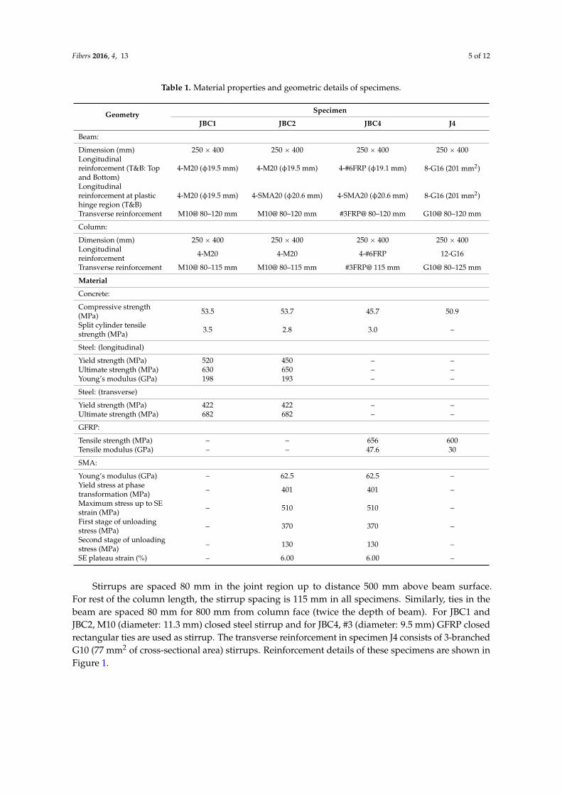
Basic properties of materials and geometric details of each specimen are presented in Table 1.Concrete is the only common material. To make these experimental results comparable, materialproperties should be similar. Average concrete compressive strength is 50.95 MPa with a coefficient ofvariation (COV) 7.31%. Likewise, the mean tensile strength of GFRP bar in specimen JBC4 and J4 is628 MPa. Steel reinforcement comprises the JBC1 only and SMA is integrated with steel in JBC2 andwith GFRP in JBC4. Further detail on material properties can be found elsewhere [7,36,37].
The geometry, longitudinal and transverse reinforcement arrangements are similar for all fourspecimens. Cross section of the column is 250 mm by 400 mm with longitudinal 4-M20 (diameter: 19.5mm) steel rebars in JBC1 and JBC2, 4-#6 (diameter: 19.1 mm) FRP rebars in JBC4 and 12-G16 GFRPbar (201 mm2 of cross-sectional area) in J4. 4-SE SMA20 (diameter: 20.6 mm) is used at the plastichinge region of the beam in JBC2 and JBC4 as longitudinal reinforcement. The plastic hinge length iscalculated as 360 mm from the face of the column [38]. The total length of 450 mm is considered forSMA bar to make provision for coupler in the joint. A new generation mechanical-adhesive type barlock couplers with flat shear bolts is used to connect SMA bars with steel and FRP bars. Effectivenessof this mechanical coupler was previously tested by Alam et al. [39] to verify their super elastic strain.
Fibers 2016, 4, 13 5 of 12
Table 1. Material properties and geometric details of specimens.
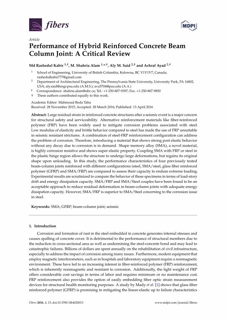
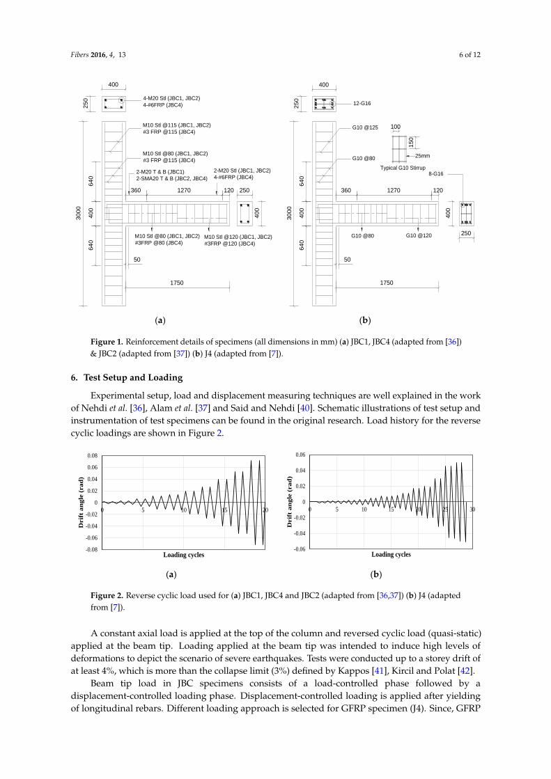
Stirrups are spaced 80 mm in the joint region up to distance 500 mm above beam surface.For rest of the column length, the stirrup spacing is 115 mm in all specimens. Similarly, ties in thebeam are spaced 80 mm for 800 mm from column face (twice the depth of beam). For JBC1 andJBC2, M10 (diameter: 11.3 mm) closed steel stirrup and for JBC4, #3 (diameter: 9.5 mm) GFRP closedrectangular ties are used as stirrup. The transverse reinforcement in specimen J4 consists of 3-branchedG10 (77 mm2 of cross-sectional area) stirrups. Reinforcement details of these specimens are shown inFigure 1.
Fibers 2016, 4, 13 6 of 12Fibers 2016, 4, 13 6 of 12
(a) (b)
Figure 1. Reinforcement details of specimens (all dimensions in mm) (a) JBC1, JBC4 (adapted from
[36]) & JBC2 (adapted from [37]) (b) J4 (adapted from [7]).
6. Test Setup and Loading
Experimental setup, load and displacement measuring techniques are well explained in the
work of Nehdi et al. [36], Alam et al. [37] and Said and Nehdi [40]. Schematic illustrations of test setup
and instrumentation of test specimens can be found in the original research. Load history for the
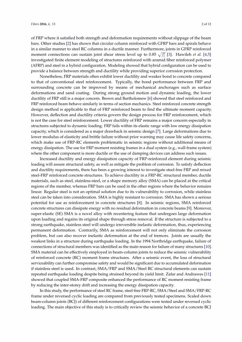
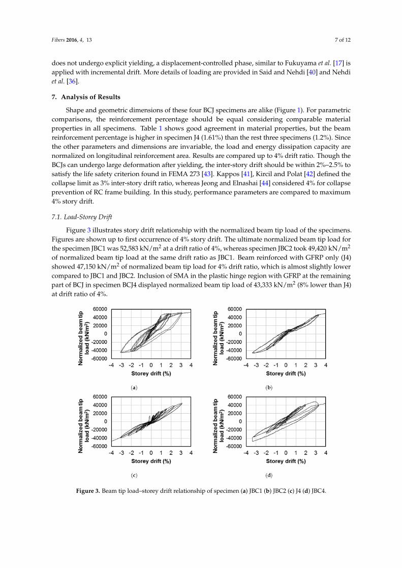
reverse cyclic loadings are shown in Figure 2.
(a) (b)
Figure 2. Reverse cyclic load used for (a) JBC1, JBC4 and JBC2 (adapted from [36, 37]) (b) J4 (adapted
from [7]).
A constant axial load is applied at the top of the column and reversed cyclic load (quasi-static)
applied at the beam tip. Loading applied at the beam tip was intended to induce high levels of
deformations to depict the scenario of severe earthquakes. Tests were conducted up to a storey drift
of at least 4%, which is more than the collapse limit (3%) defined by Kappos [41], Kircil and Polat
[42].
Beam tip load in JBC specimens consists of a load-controlled phase followed by a displacement-
controlled loading phase. Displacement-controlled loading is applied after yielding of longitudinal
rebars. Different loading approach is selected for GFRP specimen (J4). Since, GFRP does not undergo
4002
50 4-M20 Stl (JBC1, JBC2)
4-#6FRP (JBC4)
360 1270 120
30
00
64
04
00
64
0
50
250
40
0
M10 Stl @115 (JBC1, JBC2)
#3 FRP @115 (JBC4)
M10 Stl @80 (JBC1, JBC2)
#3 FRP @115 (JBC4)
2-M20 T & B (JBC1)
2-SMA20 T & B (JBC2, JBC4)
2-M20 Stl (JBC1, JBC2)
4-#6FRP (JBC4)
M10 Stl @80 (JBC1, JBC2)
#3FRP @80 (JBC4)M10 Stl @120 (JBC1, JBC2)
#3FRP @120 (JBC4)
1750
400
25
0
12-G16
360 1270 120
30
00
64
04
00
64
0
50
G10 @125
G10 @80
1750
G10 @80
G10 @120
40
0
250
8-G16
100
15
0
25mm
Typical G10 Stirrup
-0.08
-0.06
-0.04
-0.02
0
0.02
0.04
0.06
0.08
0 5 10 15 20
Drif
t a
ng
le (
ra
d)
Loading cycles-0.06
-0.04
-0.02
0
0.02
0.04
0.06
0 5 10 15 20 25 30
Drif
t a
ng
le (
ra
d)
Loading cycles
Figure 1. Reinforcement details of specimens (all dimensions in mm) (a) JBC1, JBC4 (adapted from [36])& JBC2 (adapted from [37]) (b) J4 (adapted from [7]).
6. Test Setup and Loading
Experimental setup, load and displacement measuring techniques are well explained in the workof Nehdi et al. [36], Alam et al. [37] and Said and Nehdi [40]. Schematic illustrations of test setup andinstrumentation of test specimens can be found in the original research. Load history for the reversecyclic loadings are shown in Figure 2.
Fibers 2016, 4, 13 6 of 12
(a) (b)
Figure 1. Reinforcement details of specimens (all dimensions in mm) (a) JBC1, JBC4 (adapted from
[36]) & JBC2 (adapted from [37]) (b) J4 (adapted from [7]).
6. Test Setup and Loading
Experimental setup, load and displacement measuring techniques are well explained in the
work of Nehdi et al. [36], Alam et al. [37] and Said and Nehdi [40]. Schematic illustrations of test setup
and instrumentation of test specimens can be found in the original research. Load history for the
reverse cyclic loadings are shown in Figure 2.
(a) (b)
Figure 2. Reverse cyclic load used for (a) JBC1, JBC4 and JBC2 (adapted from [36, 37]) (b) J4 (adapted
from [7]).
A constant axial load is applied at the top of the column and reversed cyclic load (quasi-static)
applied at the beam tip. Loading applied at the beam tip was intended to induce high levels of
deformations to depict the scenario of severe earthquakes. Tests were conducted up to a storey drift
of at least 4%, which is more than the collapse limit (3%) defined by Kappos [41], Kircil and Polat
[42].
Beam tip load in JBC specimens consists of a load-controlled phase followed by a displacement-
controlled loading phase. Displacement-controlled loading is applied after yielding of longitudinal
rebars. Different loading approach is selected for GFRP specimen (J4). Since, GFRP does not undergo
4002
50 4-M20 Stl (JBC1, JBC2)
4-#6FRP (JBC4)
360 1270 120
30
00
64
04
00
64
0
50
250
40
0
M10 Stl @115 (JBC1, JBC2)
#3 FRP @115 (JBC4)
M10 Stl @80 (JBC1, JBC2)
#3 FRP @115 (JBC4)
2-M20 T & B (JBC1)
2-SMA20 T & B (JBC2, JBC4)
2-M20 Stl (JBC1, JBC2)
4-#6FRP (JBC4)
M10 Stl @80 (JBC1, JBC2)
#3FRP @80 (JBC4)M10 Stl @120 (JBC1, JBC2)
#3FRP @120 (JBC4)
1750
400
25
0
12-G16
360 1270 120
30
00
64
04
00
64
0
50
G10 @125
G10 @80
1750
G10 @80
G10 @120
40
0
250
8-G16
100
15
0
25mm
Typical G10 Stirrup
-0.08
-0.06
-0.04
-0.02
0
0.02
0.04
0.06
0.08
0 5 10 15 20
Drif
t a
ng
le (
ra
d)
Loading cycles-0.06
-0.04
-0.02
0
0.02
0.04
0.06
0 5 10 15 20 25 30
Drif
t a
ng
le (
ra
d)
Loading cycles
Figure 2. Reverse cyclic load used for (a) JBC1, JBC4 and JBC2 (adapted from [36,37]) (b) J4 (adaptedfrom [7]).
A constant axial load is applied at the top of the column and reversed cyclic load (quasi-static)applied at the beam tip. Loading applied at the beam tip was intended to induce high levels ofdeformations to depict the scenario of severe earthquakes. Tests were conducted up to a storey drift ofat least 4%, which is more than the collapse limit (3%) defined by Kappos [41], Kircil and Polat [42].
Beam tip load in JBC specimens consists of a load-controlled phase followed by adisplacement-controlled loading phase. Displacement-controlled loading is applied after yieldingof longitudinal rebars. Different loading approach is selected for GFRP specimen (J4). Since, GFRP
Fibers 2016, 4, 13 7 of 12
does not undergo explicit yielding, a displacement-controlled phase, similar to Fukuyama et al. [17] isapplied with incremental drift. More details of loading are provided in Said and Nehdi [40] and Nehdiet al. [36].
7. Analysis of Results
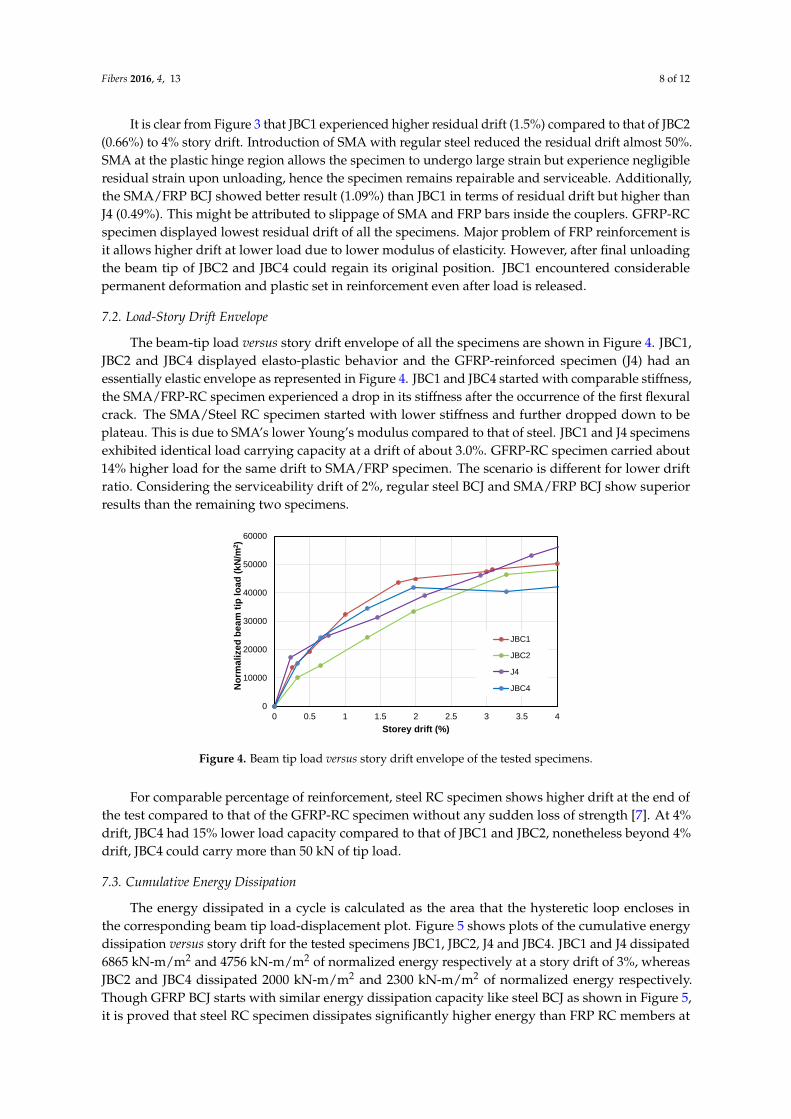
Shape and geometric dimensions of these four BCJ specimens are alike (Figure 1). For parametriccomparisons, the reinforcement percentage should be equal considering comparable materialproperties in all specimens. Table 1 shows good agreement in material properties, but the beamreinforcement percentage is higher in specimen J4 (1.61%) than the rest three specimens (1.2%). Sincethe other parameters and dimensions are invariable, the load and energy dissipation capacity arenormalized on longitudinal reinforcement area. Results are compared up to 4% drift ratio. Though theBCJs can undergo large deformation after yielding, the inter-story drift should be within 2%–2.5% tosatisfy the life safety criterion found in FEMA 273 [43]. Kappos [41], Kircil and Polat [42] defined thecollapse limit as 3% inter-story drift ratio, whereas Jeong and Elnashai [44] considered 4% for collapseprevention of RC frame building. In this study, performance parameters are compared to maximum4% story drift.
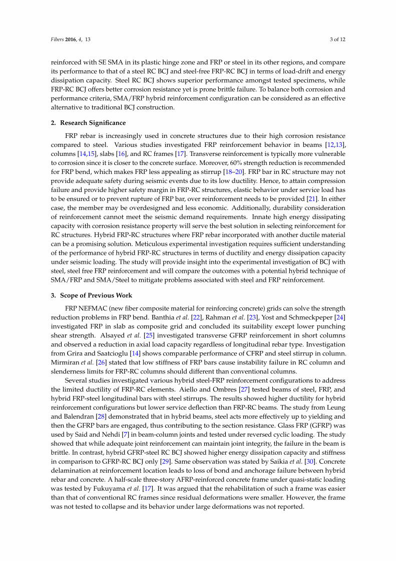
7.1. Load-Storey Drift
Figure 3 illustrates story drift relationship with the normalized beam tip load of the specimens.Figures are shown up to first occurrence of 4% story drift. The ultimate normalized beam tip load forthe specimen JBC1 was 52,583 kN/m2 at a drift ratio of 4%, whereas specimen JBC2 took 49,420 kN/m2
of normalized beam tip load at the same drift ratio as JBC1. Beam reinforced with GFRP only (J4)showed 47,150 kN/m2 of normalized beam tip load for 4% drift ratio, which is almost slightly lowercompared to JBC1 and JBC2. Inclusion of SMA in the plastic hinge region with GFRP at the remainingpart of BCJ in specimen BCJ4 displayed normalized beam tip load of 43,333 kN/m2 (8% lower than J4)at drift ratio of 4%.
Fibers 2016, 4, 13 7 of 12
explicit yielding, a displacement-controlled phase, similar to Fukuyama et al. [17] is applied with
incremental drift. More details of loading are provided in Said and Nehdi [40] and Nehdi et al. [36].
7. Analysis of Results
Shape and geometric dimensions of these four BCJ specimens are alike (Figure 1). For parametric
comparisons, the reinforcement percentage should be equal considering comparable material
properties in all specimens. Table 1 shows good agreement in material properties, but the beam
reinforcement percentage is higher in specimen J4 (1.61%) than the rest three specimens (1.2%). Since
the other parameters and dimensions are invariable, the load and energy dissipation capacity are
normalized on longitudinal reinforcement area. Results are compared up to 4% drift ratio. Though
the BCJs can undergo large deformation after yielding, the inter-story drift should be within 2%–2.5%
to satisfy the life safety criterion found in FEMA 273 [43]. Kappos [41], Kircil and Polat [42] defined
the collapse limit as 3% inter-story drift ratio, whereas Jeong and Elnashai [44] considered 4% for
collapse prevention of RC frame building. In this study, performance parameters are compared to
maximum 4% story drift.
7.1. Load-Storey Drift
Figure 3 illustrates story drift relationship with the normalized beam tip load of the specimens.
Figures are shown up to first occurrence of 4% story drift. The ultimate normalized beam tip load for
the specimen JBC1 was 52,583 kN/m2 at a drift ratio of 4%, whereas specimen JBC2 took 49,420 kN/m2
of normalized beam tip load at the same drift ratio as JBC1. Beam reinforced with GFRP only (J4)
showed 47,150 kN/m2 of normalized beam tip load for 4% drift ratio, which is almost slightly lower
compared to JBC1 and JBC2. Inclusion of SMA in the plastic hinge region with GFRP at the remaining
part of BCJ in specimen BCJ4 displayed normalized beam tip load of 43,333 kN/m2 (8% lower than
J4) at drift ratio of 4%.
Figure 3. Beam tip load–storey drift relationship of specimen (a) JBC1 (b) JBC2 (c) J4 (d) JBC4.
It is clear from Figure 3 that JBC1 experienced higher residual drift (1.5%) compared to that of
JBC2 (0.66%) to 4% story drift. Introduction of SMA with regular steel reduced the residual drift
almost 50%. SMA at the plastic hinge region allows the specimen to undergo large strain but
experience negligible residual strain upon unloading, hence the specimen remains repairable and
Figure 3. Beam tip load–storey drift relationship of specimen (a) JBC1 (b) JBC2 (c) J4 (d) JBC4.
Fibers 2016, 4, 13 8 of 12
It is clear from Figure 3 that JBC1 experienced higher residual drift (1.5%) compared to that of JBC2(0.66%) to 4% story drift. Introduction of SMA with regular steel reduced the residual drift almost 50%.SMA at the plastic hinge region allows the specimen to undergo large strain but experience negligibleresidual strain upon unloading, hence the specimen remains repairable and serviceable. Additionally,the SMA/FRP BCJ showed better result (1.09%) than JBC1 in terms of residual drift but higher thanJ4 (0.49%). This might be attributed to slippage of SMA and FRP bars inside the couplers. GFRP-RCspecimen displayed lowest residual drift of all the specimens. Major problem of FRP reinforcement isit allows higher drift at lower load due to lower modulus of elasticity. However, after final unloadingthe beam tip of JBC2 and JBC4 could regain its original position. JBC1 encountered considerablepermanent deformation and plastic set in reinforcement even after load is released.
7.2. Load-Story Drift Envelope
The beam-tip load versus story drift envelope of all the specimens are shown in Figure 4. JBC1,JBC2 and JBC4 displayed elasto-plastic behavior and the GFRP-reinforced specimen (J4) had anessentially elastic envelope as represented in Figure 4. JBC1 and JBC4 started with comparable stiffness,the SMA/FRP-RC specimen experienced a drop in its stiffness after the occurrence of the first flexuralcrack. The SMA/Steel RC specimen started with lower stiffness and further dropped down to beplateau. This is due to SMA’s lower Young’s modulus compared to that of steel. JBC1 and J4 specimensexhibited identical load carrying capacity at a drift of about 3.0%. GFRP-RC specimen carried about14% higher load for the same drift to SMA/FRP specimen. The scenario is different for lower driftratio. Considering the serviceability drift of 2%, regular steel BCJ and SMA/FRP BCJ show superiorresults than the remaining two specimens.
Fibers 2016, 4, 13 8 of 12
serviceable. Additionally, the SMA/FRP BCJ showed better result (1.09%) than JBC1 in terms of
residual drift but higher than J4 (0.49%). This might be attributed to slippage of SMA and FRP bars
inside the couplers. GFRP-RC specimen displayed lowest residual drift of all the specimens. Major
problem of FRP reinforcement is it allows higher drift at lower load due to lower modulus of
elasticity. However, after final unloading the beam tip of JBC2 and JBC4 could regain its original
position. JBC1 encountered considerable permanent deformation and plastic set in reinforcement
even after load is released.
7.2. Load-Story Drift Envelope
The beam-tip load versus story drift envelope of all the specimens are shown in Figure 4. JBC1,
JBC2 and JBC4 displayed elasto-plastic behavior and the GFRP-reinforced specimen (J4) had an
essentially elastic envelope as represented in Figure 4. JBC1 and JBC4 started with comparable
stiffness, the SMA/FRP-RC specimen experienced a drop in its stiffness after the occurrence of the
first flexural crack. The SMA/Steel RC specimen started with lower stiffness and further dropped
down to be plateau. This is due to SMA’s lower Young’s modulus compared to that of steel. JBC1 and
J4 specimens exhibited identical load carrying capacity at a drift of about 3.0%. GFRP-RC specimen
carried about 14% higher load for the same drift to SMA/FRP specimen. The scenario is different for
lower drift ratio. Considering the serviceability drift of 2%, regular steel BCJ and SMA/FRP BCJ show
superior results than the remaining two specimens.
Figure 4. Beam tip load versus story drift envelope of the tested specimens.
For comparable percentage of reinforcement, steel RC specimen shows higher drift at the end of
the test compared to that of the GFRP-RC specimen without any sudden loss of strength [7]. At 4%
drift, JBC4 had 15% lower load capacity compared to that of JBC1 and JBC2, nonetheless beyond 4%
drift, JBC4 could carry more than 50 kN of tip load.
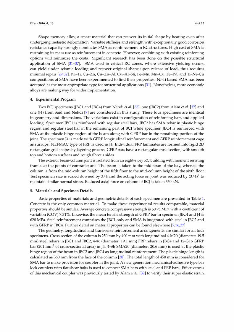
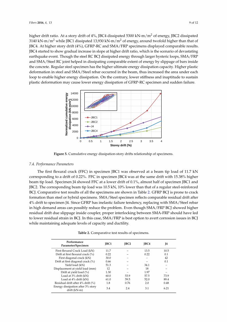
7.3. Cumulative Energy Dissipation
The energy dissipated in a cycle is calculated as the area that the hysteretic loop encloses in the
corresponding beam tip load-displacement plot. Figure 5 shows plots of the cumulative energy
dissipation versus story drift for the tested specimens JBC1, JBC2, J4 and JBC4. JBC1 and J4 dissipated
6865 kN-m/m2 and 4756 kN-m/m2 of normalized energy respectively at a story drift of 3%, whereas
JBC2 and JBC4 dissipated 2000 kN-m/m2 and 2300 kN-m/m2 of normalized energy respectively.
Though GFRP BCJ starts with similar energy dissipation capacity like steel BCJ as shown in Figure 5,
it is proved that steel RC specimen dissipates significantly higher energy than FRP RC members at
higher drift ratio. At a story drift of 4%, JBC4 dissipated 5300 kN-m/m2 of energy, JBC2 dissipated
3140 kN-m/m2 while JBC1 dissipated 13,930 kN-m/m2 of energy, around twofold higher than that of
JBC4. At higher story drift (4%), GFRP-RC and SMA/FRP specimens displayed comparable results.
0
10000
20000
30000
40000
50000
60000
0 0.5 1 1.5 2 2.5 3 3.5 4
No
rma
lize
d b
ea
m t
ip l
oa
d (
kN
/m2)
Storey drift (%)
JBC1
JBC2
J4
JBC4
Figure 4. Beam tip load versus story drift envelope of the tested specimens.
For comparable percentage of reinforcement, steel RC specimen shows higher drift at the end ofthe test compared to that of the GFRP-RC specimen without any sudden loss of strength [7]. At 4%drift, JBC4 had 15% lower load capacity compared to that of JBC1 and JBC2, nonetheless beyond 4%drift, JBC4 could carry more than 50 kN of tip load.
7.3. Cumulative Energy Dissipation
The energy dissipated in a cycle is calculated as the area that the hysteretic loop encloses inthe corresponding beam tip load-displacement plot. Figure 5 shows plots of the cumulative energydissipation versus story drift for the tested specimens JBC1, JBC2, J4 and JBC4. JBC1 and J4 dissipated6865 kN-m/m2 and 4756 kN-m/m2 of normalized energy respectively at a story drift of 3%, whereasJBC2 and JBC4 dissipated 2000 kN-m/m2 and 2300 kN-m/m2 of normalized energy respectively.Though GFRP BCJ starts with similar energy dissipation capacity like steel BCJ as shown in Figure 5,it is proved that steel RC specimen dissipates significantly higher energy than FRP RC members at
Fibers 2016, 4, 13 9 of 12
higher drift ratio. At a story drift of 4%, JBC4 dissipated 5300 kN-m/m2 of energy, JBC2 dissipated3140 kN-m/m2 while JBC1 dissipated 13,930 kN-m/m2 of energy, around twofold higher than that ofJBC4. At higher story drift (4%), GFRP-RC and SMA/FRP specimens displayed comparable results.JBC4 started to show gradual increase in slope at higher drift ratio, which is the scenario of devastatingearthquake event. Though the steel RC BCJ dissipated energy through larger hysteric loops, SMA/FRPand SMA/Steel RC joint helped in dissipating comparable extent of energy by slippage of bars insidethe concrete. Regular steel specimen has the higher ultimate energy dissipation capacity. Higher plasticdeformation in steel and SMA/Steel rebar occurred in the beam, thus increased the area under eachloop to enable higher energy dissipation. On the contrary, lower stiffness and inaptitude to sustainplastic deformation may cause lower energy dissipation of GFRP-RC specimen and sudden failure.
Fibers 2016, 4, 13 9 of 12
JBC4 started to show gradual increase in slope at higher drift ratio, which is the scenario of
devastating earthquake event. Though the steel RC BCJ dissipated energy through larger hysteric
loops, SMA/FRP and SMA/Steel RC joint helped in dissipating comparable extent of energy by
slippage of bars inside the concrete. Regular steel specimen has the higher ultimate energy dissipation
capacity. Higher plastic deformation in steel and SMA/Steel rebar occurred in the beam, thus
increased the area under each loop to enable higher energy dissipation. On the contrary, lower
stiffness and inaptitude to sustain plastic deformation may cause lower energy dissipation of GFRP-
RC specimen and sudden failure.
Figure 5. Cumulative energy dissipation-story drifts relationship of specimens.
7.4. Performance Parameters
The first flexural crack (FFC) in specimen JBC1 was observed at a beam tip load of 11.7 kN
corresponding to a drift of 0.22%. FFC in specimen JBC4 was at the same drift with 15.38% higher
beam tip load. Specimen J4 showed FFC at a lower drift of 0.1%, almost half of specimen JBC1 and
JBC2. The corresponding beam tip load was 10.5 kN, 10% lower than that of a regular steel-reinforced
BCJ. Comparative test results of all the specimens are shown in Table 2. GFRP BCJ is prone to crack
formation than steel or hybrid specimens. SMA/Steel specimen reflects comparable residual drift
after 4% drift to specimen J4. Since GFRP has inelastic failure tendency, replacing with SMA/Steel
rebar in high demand areas can possibly reduce the problem. Even though SMA/FRP BCJ showed
higher residual drift due slippage inside coupler, proper interlocking between SMA-FRP should have
led to lower residual strain in BCJ. In this case, SMA/FRP is best option to avert corrosion issues in
BCJ while maintaining adequate levels of capacity and ductility.
Table 2. Comparative test results of specimens.
Performance Parameter/Specimen JBC1 JBC2 JBC4 J4
First flexural Crack Load (kN) 11.7 – 13.5 10.5
Drift at first flexural crack (%) 0.22 – 0.22 0.1
First diagonal crack (kN) 30.0 – – 42
Drift at first diagonal crack (%) 0.66 – – 0.1
Yield load (kN) 51.3 – 34.1 –
Displacement at yield load (mm) 12 – 18 –
Drift at yield load (%) 1.30 – 1.97 –
Load at 3% drift (kN) 60.0 53.9 57.5 73.9
Load at 4% drift (kN) 61.0 59.5 52.0 89.4
Residual drift after 4% drift (%) 1.8 0.76 2.0 0.48
Energy dissipation after 3% story drift (kN-m) 3.4 2.4 3.1 6.21
0
2000
4000
6000
8000
10000
12000
14000
0 0.5 1 1.5 2 2.5 3 3.5 4
No
rmali
zed
cu
mu
lati
ve e
nerg
y
dis
sip
ati
on
(kN
-m/m
2)
Storey drift (%)
JBC1
JBC2
J4
JBC4
Figure 5. Cumulative energy dissipation-story drifts relationship of specimens.
7.4. Performance Parameters
The first flexural crack (FFC) in specimen JBC1 was observed at a beam tip load of 11.7 kNcorresponding to a drift of 0.22%. FFC in specimen JBC4 was at the same drift with 15.38% higherbeam tip load. Specimen J4 showed FFC at a lower drift of 0.1%, almost half of specimen JBC1 andJBC2. The corresponding beam tip load was 10.5 kN, 10% lower than that of a regular steel-reinforcedBCJ. Comparative test results of all the specimens are shown in Table 2. GFRP BCJ is prone to crackformation than steel or hybrid specimens. SMA/Steel specimen reflects comparable residual drift after4% drift to specimen J4. Since GFRP has inelastic failure tendency, replacing with SMA/Steel rebarin high demand areas can possibly reduce the problem. Even though SMA/FRP BCJ showed higherresidual drift due slippage inside coupler, proper interlocking between SMA-FRP should have ledto lower residual strain in BCJ. In this case, SMA/FRP is best option to avert corrosion issues in BCJwhile maintaining adequate levels of capacity and ductility.
Table 2. Comparative test results of specimens.
PerformanceParameter/Specimen JBC1 JBC2 JBC4 J4
First flexural Crack Load (kN) 11.7 – 13.5 10.5Drift at first flexural crack (%) 0.22 – 0.22 0.1
First diagonal crack (kN) 30.0 – – 42Drift at first diagonal crack (%) 0.66 – – 0.1
Drift at yield load (%) 1.30 – 1.97 –Load at 3% drift (kN) 60.0 53.9 57.5 73.9Load at 4% drift (kN) 61.0 59.5 52.0 89.4
Residual drift after 4% drift (%) 1.8 0.76 2.0 0.48Energy dissipation after 3% story
drift (kN-m) 3.4 2.4 3.1 6.21
Fibers 2016, 4, 13 10 of 12
8. Conclusions
An insight into the performance of novel hybrid structural configurations for beam column jointsubassemblages is presented in the paper for potential development of new structural solutions thatare corrosion-free ductile RC structures. Scrutinizing and analyzing the experimental test results, thefollowing conclusions can be drawn.
‚ The GFRP reinforced BCJ showed similar energy dissipation to SMA/FRP BCJ specimen athigher drift, but GFRP exhibits very low plasticity features under reversed cyclic loading. Up tocollapse limit of drift 3%, J4 showed satisfactory result. However, in extreme loading events theperformance of JBC1, JBC2 and JBC4 is expected to be superior to J4.
‚ Specimen JBC4 dissipated comparable amount of energy to that of JBC2. Nevertheless, theenergy dissipation was governed by significant slippage of FRP, steel and SMA bars. Largerhysteretic loops of steel in JBC1 resulted in higher energy dissipation compared to SMA reinforcedspecimens. Proper coupling between SMA-FRP and SMA-steel would guarantee higher energydissipation capacity due to the super elastic property of SMA.
‚ Specimen JBC2 outperformed JBC1 in terms of residual drift after unloading. JBC4 failed to do sodue to bar slippage inside couplers inside RC specimen. Although the steel RC BCJ dissipated arelatively higher amount of energy compared to that of JBC2, JBC2 performed better due to itspost-elastic strain recovery capability. This makes SMA an attractive option to replace regularsteel especially in plastic hinge region where even after high seismic activity, the BCJ can dissipatesignificant amount of energy without large residual deformation.
‚ SMA/FRP BCJ specimen displayed a force-displacement hysteresis similar to that of the steelRC BCJ with reduced stiffness and comparable residual drift. Inclusion of SE SMA at the plastichinge region was supposed to reduce residual drift significantly which hindered due to significantslippage of the FRP bar inside the couplers. However, JBC4 could still carry load beyond thecollapse limit. Such corrosion free SMA/FRP-RC structural elements can be used in highlycorrosive environments with minimum or no maintenance.
‚ FRP specimen is likely to show crack at lower load and drift ratio than steel or SMA incorporatedspecimens. This impedes the aesthetics of structure and acts as the root of subsequent damages.
Excessive residual displacement increases the probability of failure during subsequentearthquakes and makes the structure non-repairable. New construction after demolition costs agreat deal of money. To avoid life-threatening damage and keep the RC structure serviceable even afterseismic events, SMA reinforcement can be used in the plastic hinge region of RC elements. Hybridstructure like SMS/steel shows an excellent performance regarding residual drift, but coupling SMAwith FRP boosts the corrosion resistance ability to the reinforcement in RC members marking theenergy dissipation capacity.
Author Contributions: All authors contributed extensively to the study presented in this paper. Originalexperimental investigations were done by M. Shahria Alam and Aly M. Said. The study was jointly conceived bythe authors to prepare a critical review over the experimental outcomes. Md Rashedul Kabir assembled the data,analysed and prepared the manuscript under the super vision of M. Shahria Alam and Aly M. Said. Achraf Ayadadded supplementary information and edited the manuscript. All authors discussed the results, reviews andagreed to the modifications at all stages.
Conflicts of Interest: The authors declare no conflict of interest.
References
1. Mady, M.; El-Ragaby, A.; El-Salakawy, E. Seismic behavior of beam-column joints reinforced with GFRP barsand stirrups. J. Compos. Constr. 2011, 15, 875–886. [CrossRef]
2. Afifi, M.Z.; Hamdy, M.M.; Benmokrane, B. Axial capacity of circular concrete columns reinforced with GFRPbars and spirals. J. Compos. Constr. 2013, 18, 040130171. [CrossRef]
3. Hasaballa, M.; El-Salakawy, E. Shear capacity of exterior beam-column joints reinforced with GFRP bars andstirrups. J. Compos. Constr. 2015, 20, 04015047. [CrossRef]
4. Hawileh, R.A. Finite element modeling of reinforced concrete beams with a hybrid combination of steel andaramid reinforcement. Mater. Des. 2015, 65, 831–839. [CrossRef]
5. Hawileh, R.; Abdalla, J.A.; Naser, M.Z.; Tanarslan, M. Finite element modeling of shear deficient RC beamsstrengthened with NSM CFRP rods under cyclic loading. Spec. Publ. 2015, 301, 1–18.
6. Brown, V.L.; Bartholomew, C.L. FRP reinforcing bars in reinforced concrete members. ACI Mater. J. 1993, 90,34–39.
7. Said, A.; Nehdi, M. Use of FRP for RC frame in seismic zones: Part II. Performance of steel freeGFRP-reinforced beam–column joints. Appl. Compos. Mater. 2004, 11, 227–245. [CrossRef]
8. Tazarv, M.; Saiidi, M.S. Reinforcing NiTi superelastic SMA for concrete structures. J. Struct. Eng. ASCE 2014,141, 04014197. [CrossRef]
10. Mahin, S.A. Lessons from damage to steel buildings during the Northridge earthquake. Eng. Struct. 1998,20, 261–270. [CrossRef]
11. Zafar, A.; Andrawes, B. Incremental dynamic analysis of concrete moment resisting frames reinforced withshape memory composite bars. Smart Mat. St. 2012, 21, 025013. [CrossRef]
12. Toutanji, H.A.; Saafi, M. Flexural behavior of concrete beams reinforced with glass fibre-reinforced polymer(GFRP) bars. ACI Struct. J. 2000, 97, 712–719.
13. Salib, S.R.; Sayed, A.G. Prediction of crack width for fibre-reinforced polymer-reinforced concrete beams.ACI Struct. J. 2004, 101, 532–536.
14. Grira, M.; Saatcioglu, M. Reinforced concrete columns confined with steel or FRP Grids. In Proceedingsof the 8th Canadian Conference on Earthquake Engineering, Vancouver, BC, Canada, 13–18 June 1999;pp. 445–450.
15. Choo, C.C. Investigation of Rectangular Concrete Columns Reinforced or Prestressed with Fibre ReinforcedPolymer (FRP) Bars or Tendons. Ph.D. Dissertation, University of Kentucky, Lexington, KY, USA, 2005.
16. Udhayakumar, V.; Bharatkumar, B.H.; Balasubramanian, K.; Krishnamoorthy, T.S.; Lakshmanan, N.Experimental investigations on flexural behaviour of RC slabs reinforced with GFRP rebars. J. Inst. Eng.(India) Civil. Eng. Div. 2007, 88, 23–27.
17. Fukuyama, H.; Masuda, Y.; Sonobe, Y.; Tanigaki, M. Structural Performances of Concrete Frame Reinforcedwith FRP Reinforcement. In Proceedings of the Second International RILEM Symposium on Non-Metallic(FRP) Reinforcement for Concrete Structures, Ghent, Belgium, 23–25 August 1995; pp. 275–286.
18. Rizkalla, S.; Mufti, A. Reinforcing Concrete Structures with Fibre Reinforced Polymers. In ISIS CanadaManual No. 3; University of Manitoba: Winnipeg, MB, Canada, 2001.
19. El Chabib, H.; Nehdi, M.; Said, A. Evaluation of shear capacity of FRP reinforced concrete beams usingartificial neural networks. Smart Struct. Syst. 2006, 2, 81–100.
20. El Chabib, H.; Nehdi, M.; Said, A. Proposed shear design equations for FRP-reinforced concrete beams basedon genetic algorithms approach. ASCE J. Mater. Civil. Eng. 2007, 19, 1033–1042.
21. Sharbatdar, M.K.; Saatcioglu, M. Seismic design of FRP reinforced concrete structures. Asian J. Appl. Sci.2009, 2, 211–222. [CrossRef]
22. Banthia, N.; Al-Asaly, M.; Ma, S. Behavior of concrete slabs reinforced with fiber-reinforced plastic grid.J. Mater. Civil. Eng. 1995, 7, 252–257. [CrossRef]
23. Rahman, A.H.; Kingsley, C.Y.; Kobayashi, K. Service and ultimate load behavior of bridge deck reinforcedwith carbon FRP grid. J. Compos. Constr. 2000, 4, 16–23. [CrossRef]
24. Yost, J.R.; Schmeckpeper, E.R. Strength and serviceability of FRP grid reinforced bridge decks. J. Bridg. Eng.2001, 6, 605–612. [CrossRef]
25. Alsayed, S.H.; Al-Salloum, Y.A.; Almusallam, T.H.; Amjad, M.A. Concrete columns reinforced by GFRP rods.In Fourth International Symposium on Fiber-Reinforced Polymer Reinforcement for Reinforced Concrete Structures,SP-188; Dolan, C.W., Rizkalla, S.H., Nanni, A., Eds.; American Concrete Institute: Baltimore, MD, USA;November; 1999; pp. 103–112.
26. Mirmiran, A.; Yuan, W.; Chen, X. Design for slenderness in concrete columns internally reinforced withfiber-reinforced polymer bars. ACI Struct. J. 2001, 98, 116–125.
29. Nehdi, M.; Said, A. Behaviour of hybrid (Steel-GFRP) reinforced concrete frames under reversed cyclicloading. Mater. Struct. 2005, 38, 627–637. [CrossRef]
30. Saikia, B.; Thomas, J.; Ramaswamy, A.; Rao, K.S.N. Performance of hybrid rebars as longitudinalreinforcement in normal strength concrete. Mater. Struct. 2005, 38, 857–864. [CrossRef]
31. Alam, M.S.; Nehdi, M.; Youssef, M.A. Applications of Shape Memory Alloys in Earthquake Engineering.In Proceedings of the 9th Canadian Conference on Earthquake Engineering, Ontario, Canada, 26–29June 2007.
32. Alam, M.S.; Youssef, M.A.; Nehdi, M. Seismic Behaviour of Concrete Beam–Column Joints Reinforcedwith Superelastic Shape Memory Alloys. In Proceedings of the 9th Canadian Conference on EarthquakeEngineering, Ontario, Canada, 26–29 June 2007.
33. Alam, M.S.; Youssef, M.A.; Nehdi, M. Utilizing shape memory alloys to enhance the performance and safetyof civil infrastructure: A review. Can. J. Civil. Eng. 2007, 34, 1075–1086. [CrossRef]
34. Alam, M.S.; Nehdi, M.; Youssef, M.A. Shape memory alloy based smart RC bridge: overview of state of theart. Smart Struct. Syst. 2008, 4, 367–389. [CrossRef]
35. Saiidi, M.S.; Wang, H. Exploratory study of seismic response of concrete columns with shape memory alloysreinforcement. ACI Struct. J. 2006, 103, 435–442.
36. Nehdi, M.L.; Alam, M.S.; Youssef, M.A. Development of corrosion-free concrete beam-column joint withadequate seismic energy dissipation. Eng. Struct. 2010, 32, 2518–2528. [CrossRef]
37. Alam, M.S.; Youssef, M.A.; Nehdi, M.L. Analytical prediction of the seismic behaviour of superelastic shapememory alloy reinforced concrete elements. Eng. Struct. 2008, 30, 3399–3411. [CrossRef]
38. Paulay, T.; Priestley, M.N.J. Seismic Design of Reinforced Concrete and Masonry Buildings; John Wiley & SonsInc.: New York, NY, USA, 1992.
39. Alam, M.S.; Youssef, M.A.; Nehdi, M. Exploratory investigation on mechanical anchors for connecting SMAbars to steel or FRP bars. Mater. Struct. 2010, 43, 91–107. [CrossRef]
40. Said, A.; Nehdi, M. Rehabilitation of RC frame joints using local steel bracing. Struct. Infrastruct. E. 2008, 4,431–447. [CrossRef]
41. Kappos, A.J. A comparative assessment of R/C structures designed to the 1995 Eurocode 8 and the 1985CEB seismic code. Struct. Des. Tall Build. 1997, 6, 59–83. [CrossRef]
42. Kircil, M.S.; Polat, Z. Fragility analysis of mid-rise R/C frame buildings. Eng. Struct. 2006, 28, 1335–1345.[CrossRef]
43. Applied Technology Council (ATC). NEHRP Guidelines for Seismic Rehabilitation of Buildings. Rep. No.FEMA 273, Prepared for the Building Seismic Safety Council (BSSC) by the ATC; Federal Emergency ManagementAgency: Washington, DC, USA, 1997.
44. Jeong, S.H.; Elnashai, A.S. Probabilistic fragility analysis parameterized by fundamental response quantities.Eng. Struct. 2007, 29, 1238–1251. [CrossRef]