INFORMATION AND COMMUNICATION TECHNOLOGIES AND SERVICES VOLUME: 11 | NUMBER: 4 | 2013 | SEPTEMBER Edward KASEM, Roman MARSALEK, Jiri BLUMENSTEIN Department of Radio Electronics, Faculty of Electrical Engineering and Communications, Brno University of Technology, Technicka 12, 616 00 Brno, Czech Republic [email protected], [email protected], [email protected]Abstract. This paper describes the performance of LTE advanced uplink transmission in a flat Rayleigh channel. The uplink is simulated using a modified ver- sion of the Vienna uplink link level matlab code simu- lator. This modified version supports two transmission antennas instead of one. Moreover, it includes two ex- tra processes; layer mapping and precoding. In addi- tion, the demodulation reference signal is presented and employed to allow channel estimation. In this paper, the structure of the LTE advanced system is described. Furthermore, we present generation of the demodula- tion reference signal. Four combinations of two distinct channel estimation and two signal detection methods are used to provide the simulation results of perfor- mance evaluation in term of the BER and throughput curves for selected scenarios. Keywords BER, Flat Rayleigh, LTE advanced, LS, MMSE, SSD, ZF. 1. Introduction The 3rd Generation Partnership Project (3GPP) Long Term Evolution (LTE) Standard Release 10 [1], com- monly named as Long Term Evolution Advanced (LTE-A), is the next major milestone in the evolution of LTE (Release 8). This paper is a result of modifying the uplink link level matlab code simulator in order to support a new feature compared to LTE uplink link level simulator and fulfill LTE-A requirements. This feature, enhanced Multiple Input Multiple Output (MIMO) [2] [3] trans- mission, uses the Reference Signals (RS) that guar- antee efficient receiving of data information. MIMO systems, which are deployed spatial multiplexing, have emerged as one of the most promising approaches for high data rate wireless systems. Now MIMO is the main difference between LTE and LTE advanced up- link. This technique which is applied on the uplink of LTE advanced makes user equipment (UE) able to send up to four multiple unique parts of data in the same radio channel, instead of one sent in LTE uplink transmission. LTE supports a maximum of one spa- tial layer per UE (1 × 2, assuming an eNodeB diversity receiver) whereas LTE-advanced (release 10) supports up to four spatial layers of transmission allowing the possibility of 4 × 4 transmissions in the uplink, when combined with four evolved NodeB (eNodeB) receiver antennas [2] [6]. In this paper we will discuss the performance of the (2 × 2) MIMO LTE advanced system using different combinations of channel estimation and signal detec- tion. The paper is structured as follows. In Section 2, the LTE advanced system, which consists of transmit- ter and receiver, is described. A description of a flat Rayleigh channel model for (2 × 2) MIMO system is presented in Section 3. Section 4 introduces the de- modulation reference signals used for channel estima- tion. Section 5 provides an outline of channel estima- tion and signal detection algorithms. Section 6 shows performance results in terms of simulated coded bit er- ror ratio (BER) and coded throughput over different combinations of channel estimation and signal detec- tion. Finally, Section 7 concludes the paper. 2. LTE Advanced System Model In this chapter, we describe the LTE advanced up- link communication system [4]. Moreover, the differ- ences between LTE and LTE advanced system are men- tioned. The structure of the transmitter is also pre- sented depending on the 3GPP LTE advanced stan- dard [1]. c 2013 ADVANCES IN ELECTRICAL AND ELECTRONIC ENGINEERING 266
Transcript
INFORMATION AND COMMUNICATION TECHNOLOGIES AND SERVICES VOLUME: 11 | NUMBER: 4 | 2013 | SEPTEMBER
Performance of LTE ADVANCED Uplink in a Flat
Rayleigh Channel
Edward KASEM, Roman MARSALEK, Jiri BLUMENSTEIN
Department of Radio Electronics, Faculty of Electrical Engineering and Communications, Brno University ofTechnology, Technicka 12, 616 00 Brno, Czech Republic
Abstract. This paper describes the performance ofLTE advanced uplink transmission in a flat Rayleighchannel. The uplink is simulated using a modified ver-sion of the Vienna uplink link level matlab code simu-lator. This modified version supports two transmissionantennas instead of one. Moreover, it includes two ex-tra processes; layer mapping and precoding. In addi-tion, the demodulation reference signal is presented andemployed to allow channel estimation. In this paper,the structure of the LTE advanced system is described.Furthermore, we present generation of the demodula-tion reference signal. Four combinations of two distinctchannel estimation and two signal detection methodsare used to provide the simulation results of perfor-mance evaluation in term of the BER and throughputcurves for selected scenarios.
The 3rd Generation Partnership Project (3GPP) LongTerm Evolution (LTE) Standard Release 10 [1], com-monly named as Long Term Evolution Advanced(LTE-A), is the next major milestone in the evolutionof LTE (Release 8).
This paper is a result of modifying the uplink linklevel matlab code simulator in order to support a newfeature compared to LTE uplink link level simulatorand fulfill LTE-A requirements. This feature, enhancedMultiple Input Multiple Output (MIMO) [2] [3] trans-mission, uses the Reference Signals (RS) that guar-antee efficient receiving of data information. MIMOsystems, which are deployed spatial multiplexing, haveemerged as one of the most promising approaches for
high data rate wireless systems. Now MIMO is themain difference between LTE and LTE advanced up-link. This technique which is applied on the uplinkof LTE advanced makes user equipment (UE) able tosend up to four multiple unique parts of data in thesame radio channel, instead of one sent in LTE uplinktransmission. LTE supports a maximum of one spa-tial layer per UE (1×2, assuming an eNodeB diversityreceiver) whereas LTE-advanced (release 10) supportsup to four spatial layers of transmission allowing thepossibility of 4 × 4 transmissions in the uplink, whencombined with four evolved NodeB (eNodeB) receiverantennas [2] [6].
In this paper we will discuss the performance of the(2 × 2) MIMO LTE advanced system using differentcombinations of channel estimation and signal detec-tion.
The paper is structured as follows. In Section 2,the LTE advanced system, which consists of transmit-ter and receiver, is described. A description of a flatRayleigh channel model for (2 × 2) MIMO system ispresented in Section 3. Section 4 introduces the de-modulation reference signals used for channel estima-tion. Section 5 provides an outline of channel estima-tion and signal detection algorithms. Section 6 showsperformance results in terms of simulated coded bit er-ror ratio (BER) and coded throughput over differentcombinations of channel estimation and signal detec-tion. Finally, Section 7 concludes the paper.
2. LTE Advanced SystemModel
In this chapter, we describe the LTE advanced up-link communication system [4]. Moreover, the differ-ences between LTE and LTE advanced system are men-tioned. The structure of the transmitter is also pre-sented depending on the 3GPP LTE advanced stan-dard [1].
INFORMATION AND COMMUNICATION TECHNOLOGIES AND SERVICES VOLUME: 11 | NUMBER: 4 | 2013 | SEPTEMBER
2.1. Transmitter
In the transmitter, appropriate information bits aregenerated and Cyclic Redundancy Check (CRC) bitsare calculated and added. Then the output is seg-mented to the code blocks and followed by 1/3 rateturbo coder. After that, the sequences are adaptedby a rate matching process for a final suitable coderate. Moreover, the output of the rate matching ismultiplexed and interleaved to get one stream of infor-mation data called codeword. All previous operationsalso happen in the LTE transmitter, but the LTE ad-vanced transmitter can generate up to two differentstreams (codewords). This evaluation provides best inclass performance attributes such as peak data ratesand corresponding spectral efficiencies, capacity, andquality of service management. On the other hand, itis the cause of overall network complexity.
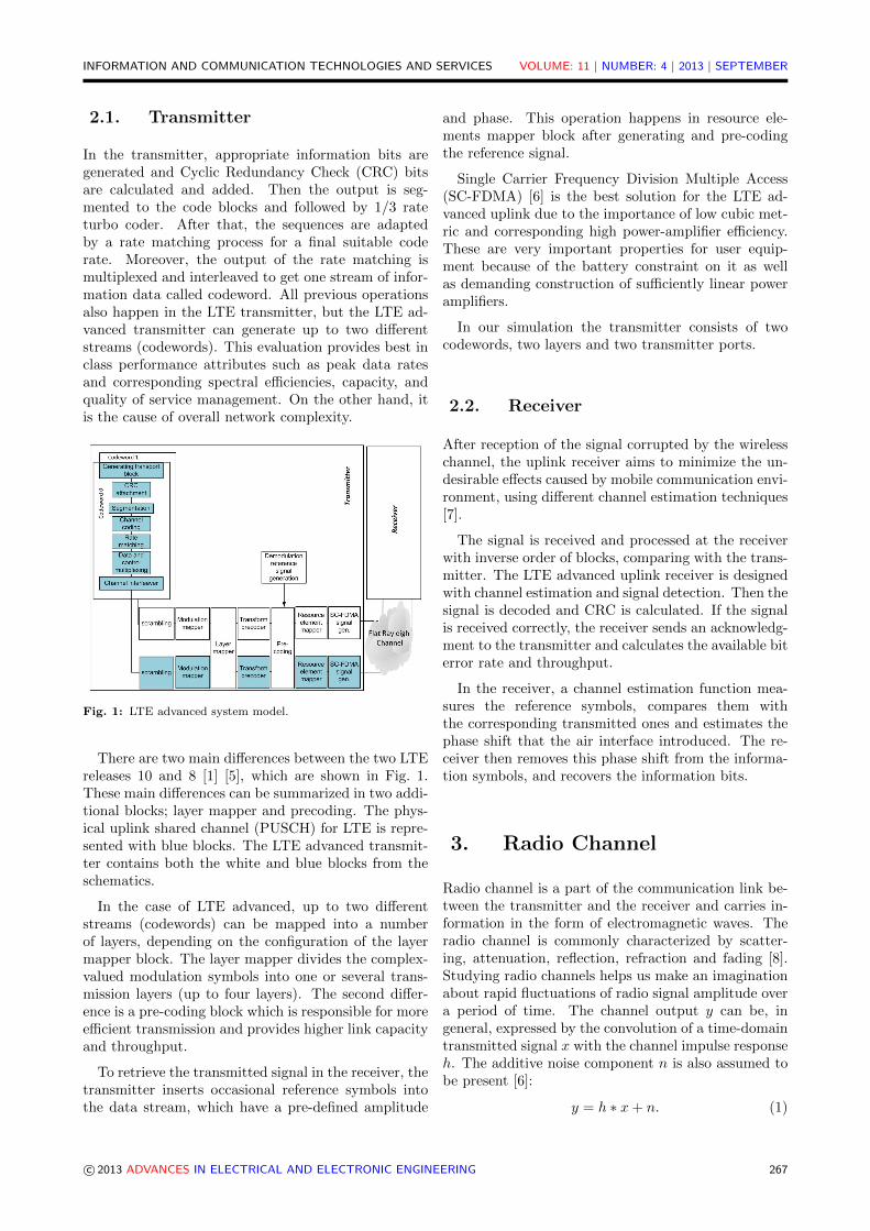
Fig. 1: LTE advanced system model.
There are two main differences between the two LTEreleases 10 and 8 [1] [5], which are shown in Fig. 1.These main differences can be summarized in two addi-tional blocks; layer mapper and precoding. The phys-ical uplink shared channel (PUSCH) for LTE is repre-sented with blue blocks. The LTE advanced transmit-ter contains both the white and blue blocks from theschematics.
In the case of LTE advanced, up to two differentstreams (codewords) can be mapped into a numberof layers, depending on the configuration of the layermapper block. The layer mapper divides the complex-valued modulation symbols into one or several trans-mission layers (up to four layers). The second differ-ence is a pre-coding block which is responsible for moreefficient transmission and provides higher link capacityand throughput.
To retrieve the transmitted signal in the receiver, thetransmitter inserts occasional reference symbols intothe data stream, which have a pre-defined amplitude
and phase. This operation happens in resource ele-ments mapper block after generating and pre-codingthe reference signal.
Single Carrier Frequency Division Multiple Access(SC-FDMA) [6] is the best solution for the LTE ad-vanced uplink due to the importance of low cubic met-ric and corresponding high power-amplifier efficiency.These are very important properties for user equip-ment because of the battery constraint on it as wellas demanding construction of sufficiently linear poweramplifiers.
In our simulation the transmitter consists of twocodewords, two layers and two transmitter ports.
2.2. Receiver
After reception of the signal corrupted by the wirelesschannel, the uplink receiver aims to minimize the un-desirable effects caused by mobile communication envi-ronment, using different channel estimation techniques[7].
The signal is received and processed at the receiverwith inverse order of blocks, comparing with the trans-mitter. The LTE advanced uplink receiver is designedwith channel estimation and signal detection. Then thesignal is decoded and CRC is calculated. If the signalis received correctly, the receiver sends an acknowledg-ment to the transmitter and calculates the available biterror rate and throughput.
In the receiver, a channel estimation function mea-sures the reference symbols, compares them withthe corresponding transmitted ones and estimates thephase shift that the air interface introduced. The re-ceiver then removes this phase shift from the informa-tion symbols, and recovers the information bits.
3. Radio Channel
Radio channel is a part of the communication link be-tween the transmitter and the receiver and carries in-formation in the form of electromagnetic waves. Theradio channel is commonly characterized by scatter-ing, attenuation, reflection, refraction and fading [8].Studying radio channels helps us make an imaginationabout rapid fluctuations of radio signal amplitude overa period of time. The channel output y can be, ingeneral, expressed by the convolution of a time-domaintransmitted signal x with the channel impulse responseh. The additive noise component n is also assumed tobe present [6]:
INFORMATION AND COMMUNICATION TECHNOLOGIES AND SERVICES VOLUME: 11 | NUMBER: 4 | 2013 | SEPTEMBER
For the simplicity, this publication adopts a FlatRayleigh channel model to describe the performance ofthe LTE advanced system. The Flat Rayleigh fadingchannel is the simplest Rayleigh channel which is usedfor narrowband transmissions over wireless and mobilecommunication channels. It is called flat because ithas a constant attenuation factor during the subframetime and the whole allocated bandwidth. In our simu-lation, the attenuation factor is described as a constantcomplex number for every symbol in the subframe. Inother words, the same complex number is applied oneach resource element (RE) within a subframe.
For our LTE advanced system model with two trans-mitters and two receiver antennas, the transmitted sig-nals are (x1,x2), received signals are (y1,y2), AWGNnoise signals are (n1,n2) with the variance σw andthe MIMO channel matrix has the following elements(h11, h12, h21, h22) for any discrete time sample. Af-ter taking these parameters into consideration we canmodel the MIMO channel using the simple matrixequation:
and k is the length of the observed signal. Figure 2describes the channel model used in our simulation.
Fig. 2: Antenna and channel configurations for (2 × 2) MIMOsystems.
4. Reference Signals
In this section, the basic structure of the uplink demod-ulation reference signal (DMRS) [1] [5] is described.DMRS is the most important component of channelestimation for efficient data reception. The LTE ra-dio frame is 10 ms long and consists of 10 subframesof length 1 ms, each subframe contains 14 symbols asshown in Fig. 3. The exact position of the physicaluplink shared channel DMRS (PUSCH DMRS) sym-bols in each uplink slot depends whether a normal orextended cyclic prefix (CP) is used [1]. In the caseof uplink, the PUSCH demodulation reference signalis located in the fourth and eleventh symbols of eachuplink subframe if this channel has a normal cyclic pre-fix and in the third and tenth symbols in the case ofextended cyclic prefix [4]. In our case, we deal withnormal cyclic prefix (14 symbols into a subframe).
4.1. Reference Signals for LTE
To support a large number of user equipment, a huge
number of reference signal sequences r(α)u,υ(n) [5] are
generated. These sequences are defined by a cyclicshift α and a base sequence ru,υ(n) according to theEq. (5).
r(α)u,υ(n) = ejαnru,υ, 0 ≤ n < MRSsc , (5)
where: u ∈ {0, 1, . . . , 29} is the group number; υ isthe base sequence number within the group; MRS
sc isthe number of subcarriers in the reference signal. Thecyclic shift α in the slot ns is given as α = 2πncs/12;ncs is defined by Eq. (6).
Fig. 3: Design of pilot pattern in a (2× 2) MIMO SC-OFDM.
ncs =(n(1)DMRS + n
(2)DMRS + nPRS(ns)
)mod12, (6)
where the value of DMRS parameters(n(1)DMRS, n
(2)DMRS
)are given according to the ta-
ble 5.5.2.1.1-2 in [5] and related to the cyclic shift
INFORMATION AND COMMUNICATION TECHNOLOGIES AND SERVICES VOLUME: 11 | NUMBER: 4 | 2013 | SEPTEMBER
parameter provided by a higher layer. nPRS(ns) iscalculated by the Eq. (7) [5], where NUL
symb is thenumber of SC-FDMA symbols in an uplink slot; c(i)is a pseudo-random sequence.
nPRS(ns) =
7∑i=0
c(8NUL
symbns + i)· 2i. (7)
The demodulation reference signal sequence in LTEsystem rPUSCH
(mMRS
sc + n)
for PUSCH is defined bythe Eq. (8) [5]. m = 1, 2 is a slot number in the sub-frame.
rPUSCH(mMRS
sc + n)
= r(α)u,υ(n). (8)
4.2. Reference Signals for LTEAdvanced
All previous DMRS equations consider only user equip-ment (UE) with a single transmit antenna. In LTE ad-vanced multiple transmit antennas are used, so DRMSshould be enhanced to meet new requirements. Thesolution for this development is generating multipleorthogonal reference signals using different phase ro-tations cyclic shifts (CSs). To provide mechanisms oforthogonally multiple DMRS transmission in MIMOspatial multiplexing schemes, LTE advanced defines
The whole process of two layers demodulation refer-ence signals generation depicts the Fig. 3. If we com-pare between the Eq. (5) and Eq. (9), we can distin-guish two main differences between DMRS in the LTEand the LTE advanced. The first one is the orthog-onal sequence ω(λ)(m) given in the table 5.5.2.1.1-1[1] which separates the generated DRMS signal in twoslots of one subframe. The second one is ncs,λ gener-ated by the Eq. (10) [1].
ncs,λ =(n(1)DMRS + n
(2)DMRS,λ + nPN(ns)
)mod12. (10)
The main difference between the Eq. (6) and Eq. (10)
is n(2)DMRS,λ parameter which changes its value between
layers to generate multiple orthogonal reference sig-nals using different phase rotations (cyclic shifts). Thismeans that Cyclic Shifts (CSs) of the DMRS base se-quence are used to generate the DMRSs for the differ-ent layers. In addition to CSs as we mention, orthog-onal cover codes (OCC) is used to get two differentreference signals with in a subframe.
5. Channel Estimation andSignal Detection
Channel estimation is one of the fundamental issueswhich should be taken into consideration for LTE ad-vanced system design. Channel estimation and signaldetection are essential solutions to recover the trans-mitted signal with minimum interference. Channel es-timation uses superimposed training sequences or pilotsymbols to calculate the channel matrix. There aredifferent techniques of channel estimation; two of themwill be presented later.
As previously described, the pilot symbols are in-serted periodically over the whole bandwidth. There-fore, block type pilot based channel estimation is anappropriate estimation method for the physical uplinksignal in the LTE advanced system.
In this section, we present two typical approachesof channel estimation that can be used for block typepilots [7], known as least square (LS) and minimummean-square error (MMSE) [9] [10].
Least square (LS) channel estimation is the simplesttechnique of channel estimation characterized by lowcomplexity. It estimates the channel response by com-puting the division between received and transmittedsymbols. The drawback of this approach is that theestimated symbols suffer from a high mean square er-ror. This algorithm minimizes ||XHest−Y||2 which de-scribes the distance between the received signal beforeand after the estimation. Y is a frequency-domain re-ceived pilot signal; X is a frequency-domain transmit-ted pilot signal; Hest is a frequency-domain estimatedchannel matrix. The LS channel estimation algorithmis based on Eq. (11) [10]:
Hest = HLS =(XHX
)−1XHY, (11)
where ()H denotes the hermitian transposition.
The minimum mean square error (MMSE) estima-tor gives better results than the LS estimator regard-ing mean square error. This estimation is based onthe block type pilot arrangement. The major disad-vantage of the MMSE estimation is its high complex-ity, which grows exponentially with a number of ob-servations. This algorithm minimizes E{||H−Hest||2}which describes the distance between the received sig-nal before and after the estimation. H is a channelmatrix in frequency-domain. The MMSE channel esti-mation algorithm is based on the Eq. (12) [10].
Hest = HMMSE = Rh,hp
(Rhp,hp + σ2
wI)−1
HLS , (12)
where Rhp,hp is the autocorrelation matrix of the chan-nel at the pilot symbol positions; Rh,hp is the cross cor-relation matrix between the channel at the data symbolpositions and the channel at the pilot symbol position
INFORMATION AND COMMUNICATION TECHNOLOGIES AND SERVICES VOLUME: 11 | NUMBER: 4 | 2013 | SEPTEMBER
and I is the identity matrix. Now for the case of theblock-type pilot channel estimation Rhp,hp = Rh,hp .
Equation (12) can be modified as:
Hest = HMMSE = Rhp,hp
(Rhp,hp + σ2
wI)−1
HLS . (13)
After estimating and calculating the channel matrix,the transmitted signal should be recovered from thereceived one. There are many signal detection tech-niques. In this publication, a zero forcing (ZF) andsoft sphere detections are mentioned.
Zero-forcing (ZF) detection is the simplest signal de-tection technique. The detection matrix G is givenby the pseudo-inverse of Hest. The disadvantage ofthis technique is unconsidered correlation between thetransmitter (user equipment) and the receiver (eN-odeB), which leads to the highest error calculation.The ZF method cannot totally remove the inter-streaminterference. It is less complex compared to the othertechniques. More information about the ZF can befound in [11].
Soft Sphere detection (SSD): The main goal behindthe SSD algorithm is to reduce the number of candidatesymbol vectors during the codeword search. It is morecomplex than the ZF, but it gives better performanceresults. More information about SSD can be found in[12].
6. Simulation and Results
All the results were obtained by modifying the LTEuplink link level simulator developed at the Instituteof Communications and Radio Frequency Engineering(INTHFT), Vienna University of Technology [13].
The LTE uplink link level simulator is one layer sim-ulator. The structure of its transmitter corresponds tothe blue blocks in the Fig. 1. The transmitter gen-erates the data for given channel quality indicators(CQIs) [14], Signal to Noise Ratio (SNR) and numberof subframes. In our case, thousand data subframeswere generated to get more accurate simulation results.The CQI value gives us two kinds of information whichare related to modulation order (4QAM, 16QAM, or64QAM) and Effective Code Rate (ECR). These dataare transmitted over the radio channel model. In thereceiver, the channel estimation and signal detectiontake place to retrieve the original transmitted signal.Then the signal is decoded to generate an acknowledg-ment (ACK/NACKs) that is sent back to the transmit-ter. In LTE original uplink link level simulator [13],perfect channel knowledge is exploited and zeros areused instead of reference signals.
The modified version has the same basic structureof LTE uplink link level simulation. Some modifica-
tions are made to support new features of LTE ad-vanced. These modifications can be clearly describedin both transmitter and receiver. In the transmitter,two codewords instead of one are generated. Then twoadditional stages (layer mapper and pre-coding) areimplemented to deal with two streams and two layersand provide more efficient receiving of the signal. Afterthat we also generate demodulation reference signalsfor LTE advanced which are described in Section 4. Allfeatures of DMRS signal are taken into consideration.In the receiver, the reverse functions of the transmitterstages take place. Some modifications are done to fit amodified version of the transmitter. Moreover, estima-tion and detection techniques are modified to allow theapplication of (2×2) MIMO. This modification can besummarized in received signal filtering for both anten-nas to extract two transmitted signals, separately.
The simulation results are described as a relationbetween Bit Error Rate (BER) and Signal to NoiseRatio (SNR). Furthermore, LTE advanced uplink per-formance in terms of UE throughput is presented. Inour simulation two estimators (LS and MMSE) and de-tection schemes (ZF and SSD) are employed. Differentcombinations of channel estimation and signal detec-tion techniques are applied to compare between theperformance of (2 × 2) MIMO and single input singleoutput (SISO) systems.
In order to verify the performance of the LTE ad-vanced system, we used different channel quality indi-cators (CQIs). For more details, we summarized thesimulation parameters in the Tab. 1.
Tab. 1: Simulation parameters.
Parameters ValuesBandwidth 1,4 MHz
FFT size (N) 128Number of data subcarriers(Ntot) 72
CP length ’normal’ [1]Subcarrier spacing 15 kHz
Transmission setting 2× 2Channel model Flat Rayleigh
Channel estimator LS, MMSEDetector ZF, SSD
Channel quality indicator 6, 9, 154QAM
Modulation schemes 16QAM64QAM
The results of simulations obtained with the modi-fied LTE simulator supporting the LTE advanced fea-tures with the parameters setup according to Tab. 1are shown in the Fig. 4 to Fig. 9. All the figures showthat the best results are achieved when we used theMMSE and SSD combination, but it makes the systemmore complex. For lower complexity but suboptimalresults, the LS and ZF combination can be used.
INFORMATION AND COMMUNICATION TECHNOLOGIES AND SERVICES VOLUME: 11 | NUMBER: 4 | 2013 | SEPTEMBER
Fig. 4: Bit Error Ratio using 4QAM modulation for differentcombinations of the estimator and detector.
Figure 4, Fig. 5 and Fig. 6 show BER results fordifferent CQI values. Seen from the point of view ofused modulations, the figures describe the bit error ratefor different modulation schemes (4QAM, 16QAM and64QAM) respectively. In the three figures the blackcurve shows the LTE (SISO) uplink performance us-ing a combination of least square (LS) and zero forc-ing techniques (ZF) [13]. The other curves give us aninsight on the performance of the LTE advanced sys-tem with various combination of channel estimationand signal detection techniques.
Fig. 5: Bit Error Ratio using 16QAM modulation for differentcombinations of the estimator and detector.
In terms of BER, the MMSE estimator slightly over-comes the performance of the LS estimator for all threeCQI values and both signal detectors. For example oftarget BER = 2 · 10−2 the required SNR differs byapproximately 3–4 dB for CQI = 6 and by 1–2 dB forCQI = 9 and 15. The use of SSD instead of the ZF de-
tector results in the relaxing of SNR requirements forgiven fixed BER for both considered estimators. Forthe same target BER = 2 · 10−2 the system with SSDrequires 6 dB lower SNR for CQI = 6, 5 dB lower SNRfor CQI = 9 and 4 dB lower SNR for CQI = 15 thanthe system using the ZF detector.
Fig. 6: Bit Error Ratio using 64QAM modulation for differentcombinations of the estimator and detector.
These curves also compare (2× 2) MIMO transmis-sion with a single input single output SISO one [13].To evaluate the (2×2) MIMO transmission we presentfour combinations of channel estimation and signal de-tection. To achieve approximately the same bit er-ror rate using a combination of LS and ZF in SISOtransmission, MMSE and ZF combination should beapplied during (2 × 2) MIMO transmission. The biterror rate for (2 × 2) MIMO transmission can be im-proved using more complex combinations (LS SSD andMMSE SSD) which were introduced in Section 5.
Fig. 7: Throughput curves using 4QAM modulation for differ-ent combinations of the estimator and detector.
INFORMATION AND COMMUNICATION TECHNOLOGIES AND SERVICES VOLUME: 11 | NUMBER: 4 | 2013 | SEPTEMBER
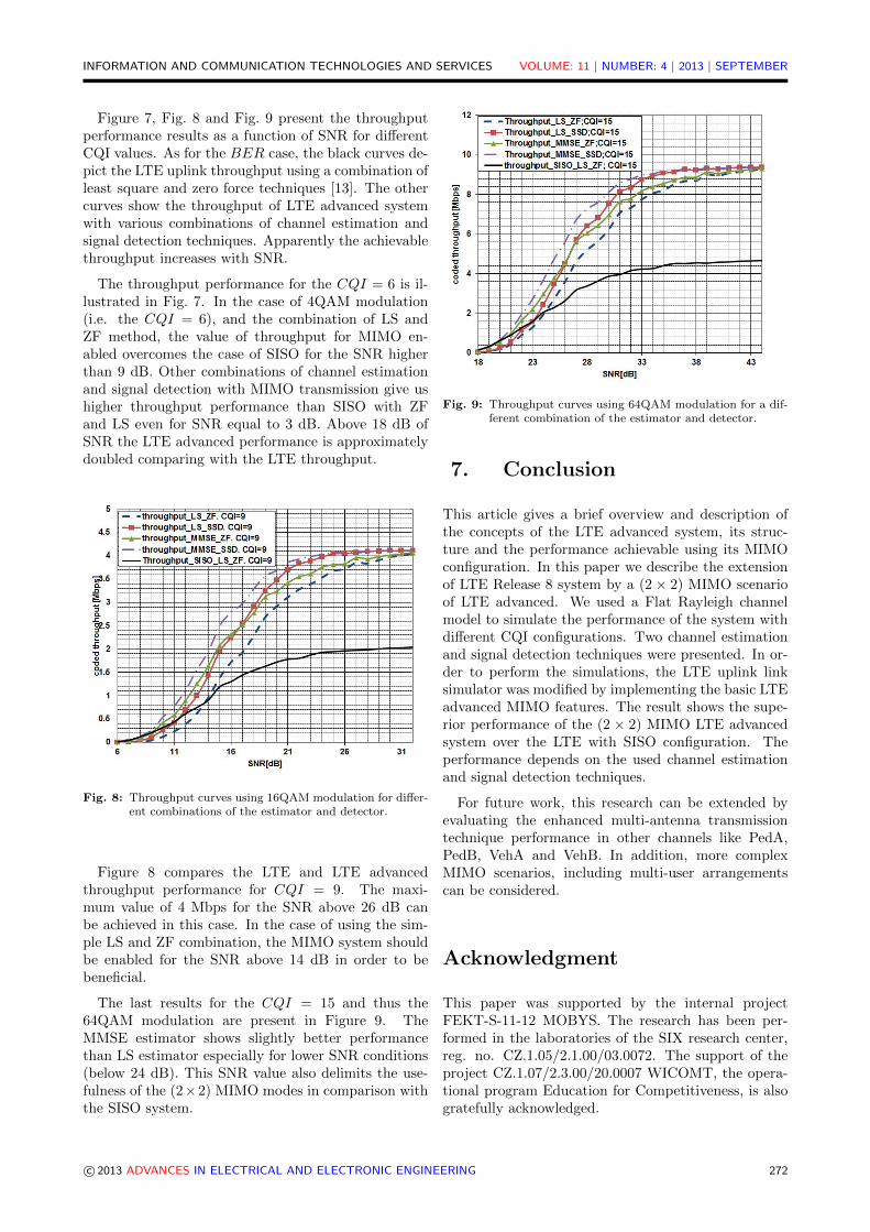
Figure 7, Fig. 8 and Fig. 9 present the throughputperformance results as a function of SNR for differentCQI values. As for the BER case, the black curves de-pict the LTE uplink throughput using a combination ofleast square and zero force techniques [13]. The othercurves show the throughput of LTE advanced systemwith various combinations of channel estimation andsignal detection techniques. Apparently the achievablethroughput increases with SNR.
The throughput performance for the CQI = 6 is il-lustrated in Fig. 7. In the case of 4QAM modulation(i.e. the CQI = 6), and the combination of LS andZF method, the value of throughput for MIMO en-abled overcomes the case of SISO for the SNR higherthan 9 dB. Other combinations of channel estimationand signal detection with MIMO transmission give ushigher throughput performance than SISO with ZFand LS even for SNR equal to 3 dB. Above 18 dB ofSNR the LTE advanced performance is approximatelydoubled comparing with the LTE throughput.
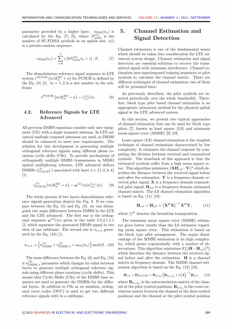
Fig. 8: Throughput curves using 16QAM modulation for differ-ent combinations of the estimator and detector.
Figure 8 compares the LTE and LTE advancedthroughput performance for CQI = 9. The maxi-mum value of 4 Mbps for the SNR above 26 dB canbe achieved in this case. In the case of using the sim-ple LS and ZF combination, the MIMO system shouldbe enabled for the SNR above 14 dB in order to bebeneficial.
The last results for the CQI = 15 and thus the64QAM modulation are present in Figure 9. TheMMSE estimator shows slightly better performancethan LS estimator especially for lower SNR conditions(below 24 dB). This SNR value also delimits the use-fulness of the (2×2) MIMO modes in comparison withthe SISO system.
Fig. 9: Throughput curves using 64QAM modulation for a dif-ferent combination of the estimator and detector.
7. Conclusion
This article gives a brief overview and description ofthe concepts of the LTE advanced system, its struc-ture and the performance achievable using its MIMOconfiguration. In this paper we describe the extensionof LTE Release 8 system by a (2 × 2) MIMO scenarioof LTE advanced. We used a Flat Rayleigh channelmodel to simulate the performance of the system withdifferent CQI configurations. Two channel estimationand signal detection techniques were presented. In or-der to perform the simulations, the LTE uplink linksimulator was modified by implementing the basic LTEadvanced MIMO features. The result shows the supe-rior performance of the (2 × 2) MIMO LTE advancedsystem over the LTE with SISO configuration. Theperformance depends on the used channel estimationand signal detection techniques.
For future work, this research can be extended byevaluating the enhanced multi-antenna transmissiontechnique performance in other channels like PedA,PedB, VehA and VehB. In addition, more complexMIMO scenarios, including multi-user arrangementscan be considered.
Acknowledgment
This paper was supported by the internal projectFEKT-S-11-12 MOBYS. The research has been per-formed in the laboratories of the SIX research center,reg. no. CZ.1.05/2.1.00/03.0072. The support of theproject CZ.1.07/2.3.00/20.0007 WICOMT, the opera-tional program Education for Competitiveness, is alsogratefully acknowledged.
INFORMATION AND COMMUNICATION TECHNOLOGIES AND SERVICES VOLUME: 11 | NUMBER: 4 | 2013 | SEPTEMBER
References
[1] 3GPP TS 36.211 Version 10.7.0. Technical spe-cification group radio access network; Physi-cal Channels and Modulation. In: 3GPP: 3rdGeneration Partnership Project [online]. 2013.Available at: http://www.3gpp.org/ftp/Specs/htmlinfo/36211.htm.
[2] SAWAHASHI, M., Y. KISHIYAMA, H. TAOKA,M. TANNO and T. NAKAMURA. BroadbandRadio Access: LTE and LTE-Advanced. In: In-ternational Symposium on Intelligent Signal Pro-cessing and Communication Systems, 2009. IS-PACS 2009. Kanazawa: IEEE, 2009, pp. 224–227. ISBN 978-1-4244-5015-2. DOI: 10.1109/IS-PACS.2009.5383862.
[3] 4G Mobile Broadband Evolution: 3GPP Re-lease 10 and Beyond HSPA+, SAE/LTE andLTE-advanced. In: 4G Americas [online]. 2012.Available at: http://www.4gamericas.org/
documents/4G%20Americas_3GPP_Rel-10_
Beyond_2.1.11%20.pdf.
[4] DAHLMAN, E., S. PARKVALL and J. SKOLD.4G: LTE/LTE-advanced for mobile broadband.Amsterdam: Academic Press, 2011. ISBN 978-0-12-385489-6.
[5] 3GPP TS 36.211 Version 8.9.0. Technical spe-cification group radio access network; Physi-cal Channels and Modulation. In: 3GPP: 3rdGeneration Partnership Project [online]. 2009.Available at: http://www.3gpp.org/ftp/Specs/htmlinfo/36211.htm.
[6] SESIA, S., I. TOUFIK and M. BAKER. LTE–the UMTS long term evolution: from theory topractice. 2nd ed. Hoboken: Wiley, 2011. ISBN 978-047-0660-256.
[7] NIRANJANE, V. B. and D. B. BHOYAR. Per-formance analysis of different channel estimationtechniques. In: International Conference on Re-cent Trends in Information Technology (ICRTIT),2011. Chennai, Tamil Nadu: IEEE, 2011, pp. 74–78. ISBN 978-1-4577-0588-5. DOI: 10.1109/ICR-TIT.2011.5972481.
[8] TRANTER, William H. Principles of communica-tion systems simulation with wireless applications.Upper Saddle River: Prentice Hall, 2003. ISBN01-349-4790-8.
[9] KEWEN, L. and X. KE. Research of MMSEand LS channel estimation in OFDM systems. In:2nd International Conference on Information Sci-ence and Engineering (ICISE), 2010. Hangzhou:IEEE, 2010, pp. 2308–2311. ISBN 978-1-4244-7616-9. DOI: 10.1109/ICISE.2010.5688562.
[10] SIMKO, M., D. WU, C. MEHLFUHRER, J. EIL-ERTZ and D. LIU. Implementation Aspects ofChannel Estimation for 3GPP LTE Terminals. In:11th European Wireless Conference 2011 - Sus-tainable Wireless Technologies (European Wire-less). Vienna: IEEE, 2011, pp. 1–5. ISBN 978-3-8007-3343-9.
[11] KIM, J. G. and W. S. CHOI. Joint ZF andpartial ML detection for uplink cellular basestation cooperation. In: International Confer-ence on ICT Convergence (ICTC), 2011. Seoul:IEEE, 2011, pp. 321–326. ISBN 978-1-4577-1267-8. DOI: 10.1109/ICTC.2011.6082606.
[12] FU, W., C. ZHAO, W. WEI and Q. KONG. Im-proved sphere decoding algorithm in TD-LTE sys-tem. In: IEEE 3rd International Conference onCommunication Software and Networks (ICCSN),2011. Xian: IEEE, 2011, pp. 514–517. ISBN 978-1-61284-485-5. DOI: 10.1109/ICCSN.2011.6013645.
[13] BLUMENSTEIN J., J. COLOM IKUNO, J.PROKOPEC and M. RUPP. Simulating the longterm evolution uplink physical layer. In: Proceed-ings ELMAR, 2011. Zadar: IEEE, 2011, pp. 141–144. ISBN 978-1-61284-949-2.
[14] KHOSHNEVIS, A., S. YAMADA, Z. YIN andS. CHOUDHURY. Resource allocation and en-coding for channel quality indicator (CQI) andCQI collided with uplink acknowledgment/negativeacknowledgment [patent]. USA. US 0088533 A1,12/902,109. Issued 7.5.2013.
About Authors
Edward KASEM received his Master degree inelectrical engineering at the Tishreen University inSyria in 2010. At present, he is a Ph.D. student atthe Department of Radio Electronics, Brno Universityof Technology. His research interests are mobilecommunication systems based on OFDM.
Roman MARSALEK graduated at the BrnoUniversity of Technology in 1999 and received thedoctoral degree from Universite de Marne-LaVallee,Ecole Superieure d’Ingenieurs en Electronique etElectrotechnique de Paris de Paris, France in 2003.He is currently assistant professor at the Departmentof Radio Electronics, Brno University of Technologyin the Czech Republic. His research interests are inwireless communications theory and applied digitalsignal processing.
Jiri BLUMENSTEIN received his Master de-gree in electrical engineering from the Brno University