Page 1
PERFORMANCE OF MULTICARRIER DS-CDMA SYSTEMS
A Project Work
ABSTRACT
In “Performance of multi-carrier DS CDMA Systems” we apply a multi-carrier
signaling technique to a direct-sequence CDMA system, where a data sequence
multiplied by a spreading sequence modulates multiple carriers, rather than a single
carrier. The receiver provides a correlator for each carrier, and the outputs of the
correlators are combined with a maximal-ratio combiner. This type of signaling has the
desirable properties of exhibiting a narrowband interference suppression effect, along
with robustness to fading, without requiring the use of either an explicit RAKE structure
or an interference suppression filter.
We use band limited spreading waveforms to prevent self-interference, and we evaluate
system performance over a frequency selective Rayleigh channel in the presence of
partial band interference. There is no interference from the CDMA signals to the existing
microwave systems. Thus, there is no need for either a narrowband suppression filter at
the receiver or a notch filter at the transmitter. Simulation results compare system
performance with that of a single-carrier RAKE system.
Page 2
ii
CHAPTER 1
1.1 INTRODUCTION:
Direct sequence spread spectrum (DS-SS) techniques to multiple access communications.
This is partly due to its multiple access capability, robustness against fading, and anti-
interference capability.
In direct sequence spread spectrum, the stream of information to be transmitted is divided
into small pieces, each of which is allocated across to a frequency channel across the
spectrum. A data signal at the point of transmission is combined with a higher data-rate
bit sequence (also known as a chipping code) that divides the data according to a
spreading ratio. The redundant chipping code helps the signal resist interference and also
enables the original data to be recovered if data bits are damaged during transmission.
1.2 PROBLEM STATEMENT:
Direct sequence (DS) waveforms have a wide bandwidth, anytime that bandwidth
exceeds the coherence bandwidth of the channel, the fading tends to be frequency
selective, and a RAKE receiver can be used to enhance system performance. Anti-
interference capability in a DS system is achieved by correlating the received signal with
the predetermined spreading sequence, thus allowing the inherent processing gain of the
system to attenuate the interference. Further, an interference suppression filter can be
utilized to reject strong narrowband interference.
We need to design a system with less interference without using any external circuitry.
Page 3
1.3 OBJECTIVE
• The main objective is to find the probability of Bit Error Rate (BER) for the
Multi-Carrier CDMA.
• Simulation Results shows BER is less for Multi Carrier as compared to single
Carrier CDMA
1.4 EXSISTED METHOD (SC-CDMA):
Single-carrier code division multiple access (SC-CDMA), also named cyclic-prefix
CDMA in the literature, is a promising air interface for the uplink of the 4G cellular
wireless communication systems. It enables the high capacity intrinsically offered by
CDMA by making the equalization of the multipath channels and the mitigation of the
resulting interference possible at a low complexity. SC-CDMA technique has flexibility
for providing variable rate transmissions, yet retaining multiple access capability.
In singlecarier DS SS system a data sequence multiplied by a spreading sequence
modulates a single carrier. The receiver provides a correlator by which original data
sequence can be extracted. This type of system has the following advantages: the fading
tends to be frequency selective, and a RAKE receiver can be used to enhance system
performance. An interference suppression filter can be utilized to reject strong
narrowband interference.
In single carrier DS SS system multipath interference is because the delayed versions of
the transmitted pseudorandom codes will have poor correlation with the original
pseudorandom code, and will thus appear as another user, which is ignored at the
receiver. In other words, as long as the multipath channel induces at least one chip of
delay, the multipath signals will arrive at the receiver such that they are shifted in time by
Page 4
at least one chip from the intended signal. The correlation properties of the
pseudorandom codes are such that this slight delay causes the multipath to appear
uncorrelated with the intended signal, and it is thus ignored.
Hence this system uses a rake receiver which is a radio receiver designed to counter the
effects of multipath fading. It does this by using several "sub-receivers" called fingers,
that is, several correlators each assigned to a different multipath component. Each finger
independently decodes a single multipath component; at a later stage the contribution of
all fingers are combined in order to make the most use of the different transmission
characteristics of each transmission path i.e., rake receiver combines the information
from several correlators, each one tuned to a different path delay, producing a stronger
version of the signal than a simple receiver with a single correlator tuned to the path
delay of the strongest signal.
The multipath channel through which a radio wave transmits can be viewed as
transmitting the original (line of sight) wave plus a number of multipath components.
Multipath components are delayed copies of the original transmitted wave traveling
through a different echo path, each with a different magnitude and time-of-arrival at the
receiver. Since each component contains the original information, if the magnitude and
time-of-arrival (phase) of each component is computed at the receiver (through a process
called channel estimation), then all the components can be added coherently to improve
the information reliability.
But on the other hand, spreading codes that give perfect isolation from other users at the
output of a correlation receiver are called orthogonal codes, and a number of such code
sets exist. The problem in practice is that orthogonality between codes is impossible to
maintain at the receiver, because of asynchronism and channel delay spread. Both effects
are present on the uplink (or reverse link), while only the latter is seen on the downlink of
a wireless channel. The correlation receiver, which in a multipath channel becomes the
celebrated Rake receiver, cannot then perfectly separate the signals for the multiple users.
The resulting multiaccess interference (MAI) causes a severe degradation in
Page 5
performance, and may render the system useless for even moderate user loads with equal
power received from each user. The need for MAI suppression is therefore clear. Hence
we go for MC-CDMA.
1.5 PROPOSED METHOD (MC-CDMA):
Multi-Carrier Code Division Multiple Access (MC-CDMA) is a multiple access
scheme used in OFDM-based telecommunication systems, allowing the system to support
multiple users at the same time.
MC-CDMA spreads each user symbol in the frequency domain. That is, each user
symbol is carried over multiple parallel subcarriers, but it is phase shifted (typically 0 or
180 degrees) according to a code value. The code values differ per subcarrier and per
user. The receiver combines all subcarrier signals, by weighing these to compensate
varying signal strengths and undo the code shift. The receiver can separate signals of
different users, because these have different (e.g. orthogonal) code values.
Since each data symbol occupies a much wider bandwidth (in hertz) than the data rate (in
bit/s), a signal-to-noise-plus-interference ratio (if defined as signal power divided by total
noise plus interference power in the entire transmission band) of less than 0 dB is
feasible.
For the case of MC-DS-CDMA where OFDM is used as the modulation scheme, the data
symbols on the individual subcarriers are spread in time by multiplying the chips on a PN
code by the data symbol on the subcarrier. By using a multicarrier DS system we can
reduce multiaccess interference MAI because here the entire bandwidth of the system is
divided into M (not necessarily contiguous) equi-width frequency bands, and thus each
carrier frequency is modulated by a spreading sequence with a chip duration which is M
times as long as that of a single-carrier system. Hence in this system the codes need not
be orthogonal to each other.
Page 6
This type of system has the following advantages:
Multi-carrier DS SS system is robust to multipath fading.
Multi-carrier system has a narrowband interference suppression effect and finally,
a lower chip rate is required.
1.6 THESIS ORGANIZATION:
First chapter described the problem statement and how the proposed method
advantageous over the previous methods. Chapter 2 giving background information for
all the keywords which we have described in proposed method. Chapter 3 gives the
detail description for the proposed method. Chapter 4 is about communication tools in
MATLAB which we have used in this project .Chapter 5 showing simulation results and
Chapter 6 giving conclusion and future scope
Page 7
CHAPTER 2
MULTIPLE ACCESS TECHNIQUES
One of the basic concepts in data communication is the idea of allowing several
transmitters to send information simultaneously over a single communication channel.
This allows several users to share a bandwidth of frequencies. This concept is called
multiplexing. There are three basic multiplexing techniques,
They are:
1. Frequency division multiple access (FDMA).
2. Time division multiple access (TDMA).
3. Code division multiple access (CDMA).
2.1 MULTIPLEXING TECHNIQUES:
2.1.1 FDMA:
Frequency Division Multiple Access or FDMA is a channel access method used in
multiple-access protocols as a channelization protocol. FDMA gives users an individual
allocation of one or several frequency bands, allowing them to utilize the allocated radio
spectrum without interfering with each other. Multiple Access systems coordinate access
between multiple users.
Page 8
FDMA requires high-performing filters in the radio hardware, in contrast to
TDMA and CDMA.
FDMA is not vulnerable to timing problems as TDMA. Since a predetermined
frequency band is available for the entire period of communication, stream data (a
continuous flow of data that may not be packetized) can easily be used with
FDMA.
Due to the frequency filtering, FDMA is not sensitive to near-far problem which
is pronounced for CDMA.
It is important to distinguish between FDMA and frequency-division duplexing (FDD).
While FDMA allows multiple users simultaneous access a certain system, FDD refers to
how the radio channel is shared between the uplink and downlink (for instance, the traffic
going back and forth between a mobile-phone and a base-station). Furthermore,
frequency-division multiplexing (FDM) should not be confused with FDMA. The former
is a physical layer technique that combines and transmits low-bandwidth channels
through a high-bandwidth channel. FDMA, on the other hand, is an access method in the
data link layer.
FDMA also supports demand assignment in addition to fixed assignment. Demand
assignment allows all users apparently continuous access of the radio spectrum by
assigning carrier frequencies on a temporary basis using a statistical assignment process.
2.1.2 TDMA:
Time division multiple access (TDMA) is a channel access method for shared medium
networks. It allows several users to share the same frequency channel by dividing the
signal into different time slots. The users transmit in rapid succession, one after the other,
each using his own time slot. This allows multiple stations to share the same transmission
medium (e.g. radio frequency channel) while using only a part of its channel capacity.
TDMA is used in the digital 2G cellular systems such as Global System for Mobile
Communications (GSM), IS-136, Personal Digital Cellular (PDC) and iDEN, and in the
Digital Enhanced Cordless Telecommunications (DECT) standard for portable phones. It
Page 9
is also used extensively in satellite systems, and combat-net radio systems. TDMA frame
structure showing a data stream divided into frames and those frames divided into time
slots.
TDMA is a type of Time-division multiplexing, with the special point that instead of
having one transmitter connected to one receiver, there are multiple transmitters. In the
case of the uplink from a mobile phone to a base station this becomes particularly
difficult because the mobile phone can move around and vary the timing advance
required to make its transmission match the gap in transmission from its peers.
2.1.3 CDMA:
Code division multiple access (CDMA) is a form of multiplexing, which allows
numerous signals to occupy a single transmission channel, optimizing the use of available
bandwidth i.e., in CDMA both data and voice are separated from signals using codes and
then transmitted using a wide frequency range. Because of this, there are more space left
for data transfer and this was one of the major reasons why CDMA is the preferred
technology for the 3G generation, which is broadband access and the use of big
multimedia messages. 14% of the worldwide market goes to CDMA. It is a channel
access method utilized by various radio communication technologies. The technology is
used in ultra-high-frequency (UHF) cellular telephone systems in the 800-MHz and 1.9-
GHz bands.
Code division multiple access (CDMA) has advantages over traditional multiple access
techniques such as time division multiple access (TDMA), or frequency division multiple
access (FDMA), in that it does not require coordination of the users in time. This has
recently been exposed as an apparent advantage as a technique for use in a cellular
context because it is an efficient technique to achieve spatial re-use.
These multiple access schemes can be shown as follows:
Page 10
Fig 2.1: Multiple Access Schemes
As shown in fig 2.1, FDMA puts each call on a separate frequency and TDMA assigns
each call a certain portion of time on a designated frequency for the above mentioned
purpose. But CDMA gives a unique code to each call and spreads it over the available
frequencies i.e., CDMA employs spread-spectrum technology and a special coding
scheme (where each transmitter is assigned a code) to allow multiple users to be
multiplexed over the same physical channel. Thus CDMA is a form of "spread-spectrum"
signaling, since the modulated coded signal has a much higher data bandwidth than the
data being communicated. All these are multiple access systems because more than one
user can use the specified CELL (not cell phone!) at a time.
An analogy to the problem of multiple access is a room (channel) in which people wish to
communicate with each other. To avoid confusion, people could take turns speaking
(time division), speak at different pitches (frequency division), or speak in different
languages (code division). CDMA is analogous to the last example where people
speaking the same language can understand each other, but not other people. Similarly, in
radio CDMA, each group of users is given a shared code. Many codes occupy the same
channel, but only users associated with a particular code can understand each other.
Advantages of CDMA:
Higher bandwidth.
Page 11
Greater level of privacy and security to the communication.
Lesser radiation while using cell phones.
Due to these advantages there is high probability that CDMA technology will dominate
the future of mobile communications. It is expected that in future CDMA will become
superior and all the major cell operators will have a migration to CDMA.
2.2 SPREAD SPECTRUM TECHNIQUES:
Spread spectrum systems are becoming more and more popular, especially as the
available frequency spectrum is becoming more and more crammed. Although these
systems are extremely complex and expensive, they have numerous advantages over
conventional systems. The major advantage of these systems in the signal security that
the systems present. Unlike conventional systems it is extremely difficult to eavesdrop on
a conversation that takes place over a spread spectrum system.
Spread spectrum systems spread the signal over as wide bandwidth as possible. Also they
try to hide the transmitted signal as close to the background noise as possible. This makes
the communication very difficult to find in the frequency spectrum and cannot be easily
tracked and more difficult to jam. There are three different types of spread spectrum
techniques that can be used. These are:
Frequency hopping
Time hopping
Direct sequence
2.2.1 FREQUENCY HOPPING:
In frequency hopping CDMA, the carrier frequency of the modulated information signal
is not constant but changes periodically. During time intervals T the carrier frequency
remains the same, but after each time interval the carrier hops to another (or possibly the
Page 12
same) frequency. The hopping pattern is decided by the code signal. The set of available
frequencies the carrier can attain is called the hop-set.
The frequency occupation of an FH-SS system differs considerably from a DS-SS
system. A DS system occupies the whole frequency band when it transmits, whereas an
FH system uses only a small part of the bandwidth when it transmits, but the location of
this part differs in time.
Within frequency hopping CDMA a distinction is made that is based on the hopping rate
of the carrier. If the hopping rate is (much) greater than the symbol rate, one speaks of a
fast frequency hopping (F-FH). In this case the carrier frequency changes a number of
times during the transmission of one symbol, so that one bit is transmitted in different
frequencies. If the hopping rate is (much) smaller than the symbol rate, one speaks of
slow frequency hopping (S-FH). In this case multiple symbols are transmitted at the same
frequency.
The occupied bandwidth of the signal on one of the hopping frequencies depends not
only on the bandwidth of the information signal but also on the shape of the hopping
signal and the hopping frequency. If the hopping frequency is much smaller than the
information bandwidth (which is the case in slow frequency hopping), then the
information bandwidth is the main factor that decides the occupied bandwidth. If,
however, the hopping frequency is much greater than the information bandwidth, the
pulse shape of the hopping signal will decide the occupied bandwidth at one hopping
frequency. If this pulse shape is very abrupt (resulting in very abrupt frequency changes),
the frequency band will be very broad, limiting the number of hop frequencies. If we
make sure that the frequency changes are smooth, the frequency band at each hopping
frequency will be about 1/Th times the frequency bandwidth, where Th is equal to the
hopping frequency. We can make the frequency changes smooth by decreasing the
transmitted power before a frequency hop and increasing it again when the hopping
frequency has changed.
Page 13
2.2.2 TIME HOPPING:
In time hopping CDMA the data signal is transmitted in rapid bursts at time intervals
determined by the code assigned to the user. The time axis is divided into frames, and
each frame is divided into M time slots. During each frame the user will transmit in one
of the M time slots. Which of the M time slots is transmitted depends on the code signal
assigned to the user. Since a user transmits all of its data in one, instead of M time slots,
the frequency it needs for its transmission has increased by a factor M.
The multiple access capability of TH-SS signals is acquired in the same manner as that of
the FH-SS signals; namely, by making the probability of users' transmissions in the same
frequency band at the same time small. In the case of time hopping all transmissions are
in the same frequency band, so the probability of more than one transmission at the same
time must be small. This is again achieved by assigning different codes to different users.
If multiple transmissions do occur, error-correcting codes ensure that the desired signal
can still be recovered. If there is synchronization among the users, and the assigned codes
are such that no more than one user transmits at a particular slot, then the TH-CDMA
reduces to a TDMA scheme where the slot in which a user transmits is not fixed but
changes from frame to frame.
Multipath interference:
In the time hopping CDMA, a signal is transmitted in reduced time. The signaling rate,
therefore, increases and dispersion of the signal will now lead to overlap of adjacent bits.
Therefore, no advantage is to be gained with respect to multipath interference rejection.
Narrowband interference:
A TH-CDMA signal is transmitted in reduced time. This reduction is equal to 1/Gp,
where Gp is the processing gain. At the receiver we will only receive an interfering signal
Page 14
during the reception of the desired signal. Thus, we only receive the interfering signal
1/Gp percent of the time, reducing the interfering power by a factor Gp.
2.2.3 DIRECT SEQUENCE:Direct sequence spread spectrum, also known as direct sequence code division multiple
access (DS-CDMA), and is one of two approaches to spread spectrum modulation for
digital signal transmission over the airwaves.
Direct sequence contrasts with the other spread spectrum process, known as frequency
hopping spread spectrum, or frequency hopping code division multiple access (FH-
CDMA), in which a broad slice of the bandwidth spectrum is divided into many possible
broadcast frequencies. In general, frequency-hopping devices use less power and are
cheaper, but the performance of DS-CDMA systems is usually better and more reliable.
Spread spectrum first was developed for use by the military because it uses wideband
signals that are difficult to detect and that resist attempts at jamming. In recent years,
researchers have turned their attention to applying spread spectrum processes for
commercial purposes, especially in local area wireless networks.
Signal transmission consists of the following steps:
1. A pseudo-random code is generated, different for each channel and each successive connection.
2. The Information data modulates the pseudo-random code (the Information data is “spread”).
3. The resulting signal modulates a carrier.
4. The modulated carrier is amplified and broadcast.
Signal reception consists of the following steps:
Page 15
1. The carrier is received and amplified.
2. The received signal is mixed with a local carrier to recover the spread digital signal.
3. A pseudo-random code is generated, matching the anticipated signal.
4. The receiver acquires the received code and phase locks its own code to it.
5. The received signal is correlated with the generated code, extracting the Information data.
Generating Pseudo-Random Codes:
For each channel the base station generates a unique code that changes for every
connection. The base station adds together all the coded transmissions for every
subscriber. The subscriber unit correctly generates its own matching code and uses it to
extract the appropriate signals. Note that each subscriber uses several independent
channels.
In order for all this to occur, the pseudo-random code must have the following properties:
1. It must be deterministic. The subscriber station must be able to independently generate the code that matches the base station code.
2. It must appear random to a listener without prior knowledge of the code (i.e. it has the statistical properties of sampled white noise).
3. The cross-correlation between any two codes must be small (see below for more information on code correlation).
4. The code must have a long period (i.e. a long time before the code repeats itself).
Page 16
Fig 2.2(a): Pseudo-noise spreading
Here the duration of an element in the code is called the "chip time". The ratio between
the user symbol time and the chip time is called the spread factor or processing gain. This
is a theoretical system gain that reflects the relative advantage that frequency spreading
provides.
Code Correlation:
In this context, correlation has a specific mathematical meaning. In general the
correlation function has these properties:
It equals 1 if the two codes are identical
It equals 0 of the two codes have nothing in common
Intermediate values indicate how much the codes have in common. The more they have
in common, the harder it is for the receiver to extract the appropriate signal.
There are two correlation functions:
Cross-Correlation: The correlation of two different codes. As we’ve said, this
should be as small as possible.
Auto-Correlation: The correlation of a code with a time-delayed version of itself.
In order to reject multi-path interference, this function should equal 0 for any time
delay other than zero.
The receiver uses cross-correlation to separate the appropriate signal from signals meant
for other receivers, and auto-correlation to reject multi-path interference.
Now, in Direct Sequence spread spectrum transmission, the user data signal is multiplied
by a code sequence. Mostly, binary sequences are used. This noise signal is a
pseudorandom sequence of 1 and −1 values, at a frequency much higher than that of the
original signal, thereby spreading the energy of the original signal into a much wider
band.
Page 17
Fig 2.2(b): Frequency-Spreading
The transmit signal occupies a bandwidth that equals the spread factor times the
bandwidth of the user data.
In the receiver, the received signal is again multiplied by the same (synchronized) code.
This operation removes the code, so we recover the transmitted user data.
Page 18
Different CDMA users use different codes. In this example the receiver sees the signal
from user 1, while the signal from user 2 is heavily attenuated by the correlator
(multiplier and integrator) in the receiver
CHAPTER 3
LIMITATIONS OF NOISE
3.1 INTERFERENCE IN CDMA:
The colored interference model used here is more suitable than the white noise model
when jamming signals and/or co-channel interference (CCI) are present in the wireless
communication system.
3.1.1 CO-CHANNEL INTERFERENCE (CCI):
In frequency reuse two co-channels use same set of frequencies. In this case a mobile unit
in one cell may receive a weak signal from another co-channel cell. This kind of
interference is called co-channel interference. A minimum amount of distance must be
maintained between co-channels in order to reduce the co-channel interference.
Page 19
Fig 3.1: Co-channel interference at the mobile unit
We can express the interfering signal transmitted from the ith transmit antenna of the mth
interferer as
Where Pm is the transmit power of the mth interferer, and are data symbols
transmitted from the ith transmit antenna of the mth interferer. The data symbols are
assumed to be i.i.d. binary random variables with zero mean and unit variance. In
addition, is the symbol waveform and T is the symbol duration. It is assumed that
the receiver is synchronized to the desired user but not necessarily to the interfering
signals and is the symbol timing difference between the mth interferer and the
desired user signal. Without loss of generality, we assume 0 < <T. The elements of the
interference symbol matrix Si are samples at the matched filter output at the receiver at
time index jT . The (j,i)th element of Si is
Where
Page 20
is the autocorrelation of the symbol waveform. For the CCI, the temporal interference
correlation is due to the intersymbol interference in the sampled interfering signals.
Jamming signals:
We assume that there are two jammers, each with three transmit antennas, in the system.
The jamming signals are modeled as first-order AR processes driven by temporally white
Gaussian processes
where represents the jamming signal transmitted from the ith transmit antenna of
the mth jammer at the ith time index, is the temporal correlation coefficient,
and has zero mean with variance , which decides the transmit power of the mth
jammer. The signal-to-interference ratio is set to be 3 dB. The total channel estimation
MSEs for the high spatial correlation channel and low spatial correlation channel,
respectively. For the AR jammers, similar conclusions on the estimation performance
achieved by different training sequences can be made as in the case of CCI.
3.1.2 MULTIPLE ACCESS INTERFERENCE (MAI):
Direct-sequence spread spectrum (DS-SS) will be used in most implementations of the
third generation of cellular mobile communication systems (popularly known as 3G) for
fixed-assignment multiple access. This means that a central controller (or base station) is
responsible for the allocation of channel resources to all users who want to communicate
at the same time within its physical domain.
Page 21
Although nowadays CDMA is commonly linked with 3G because of the latter's
increasing public visibility, its applications are certainly not limited to this. For instance,
wireless local area networks (WLANs) and wireless local loops (WLLs) can also make
use of this technology and are already starting to do so. This makes an understanding of
the strengths and limitations of CDMA important to the engineer. One of those
limitations is the existence of multi-access interference (MAI).
The multi-user systems have the interesting property that their capacity is typically
limited by multiple-access interference (MAI) or multi-user interference (MUI), rather
than noise. Two quite different, suboptimal approaches for multi-user detection (MUD)
emerged, which had much lower complexity than the optimum multi-user detector:
Interference cancellation (IC).
Adaptive filtering.
3.2 TYPES OF FADING CHANNELS:
Fading is the phenomena of reduction in the signal power means of reflection refraction
and diffraction.
The terms slow and fast fading refer to the rate at which the magnitude and phase change
imposed by the channel on the signal changes. The coherence time is a measure of the
minimum time required for the magnitude change of the channel to become decorrelated
from its previous value.
3.2.1 SLOW FADING:
When the coherence time of the channel is large relative to the delay constraint of the
channel. In this regime, the amplitude and phase change imposed by the channel can be
considered roughly constant over the period of use. Slow fading can be caused by events
such as shadowing, where a large obstruction such as a hill or large building obscures the
Page 22
main signal path between the transmitter and the receiver. The amplitude change caused
by shadowing is often modeled using a log-normal distribution with a standard deviation
according to the log-distance path loss model.
3.2.2 FAST FADING:
Fast fading occurs when the coherence time of the channel is small relative to the delay
constraint of the channel. In this regime, the amplitude and phase change imposed by the
channel varies considerably over the period of use.
In a fast-fading channel, the transmitter may take advantage of the variations in the
channel conditions using time diversity to help increase robustness of the communication
to a temporary deep fade. Although a deep fade may temporarily erase some of the
information transmitted, use of an error-correcting code coupled with successfully
transmitted bits during other time instances (interleaving) can allow for the erased bits to
be recovered. In a slow-fading channel, it is not possible to use time diversity because the
transmitter sees only a single realization of the channel within its delay constraint. A deep
fade therefore lasts the entire duration of transmission and cannot be mitigated using
coding.
Fading models:
Examples of fading models for the distribution of the attenuation are:
Nakagami fading
Weibull fading
Rayleigh fading
Rician fading
Log-normal shadow fading
Page 23
3.3 RAKE RECEIVER:
Multipath channel:
Due to reflections from obstacles a radio channel can consist of many copies of originally
transmitted signals having different amplitudes, phases, and delays Multipath can occur
in radio channel in various ways Reflection, diffraction, scattering The RAKE receiver
uses a multipath diversity principle – It rakes the energy from the multipath propagated
signal components
Fig 3.3 (a): Multipath propagation of signal
A rake receiver is a radio receiver designed to counter the effects of multipath fading. It
does this by using several "sub-receivers" each delayed slightly in order to tune in to the
individual multipath components. Each component is decoded independently, but at a
later stage combined in order to make the most use of the different transmission
Page 24
characteristics of each transmission path. This could very well result in higher SNR (or
Eb/No) in a multipath environment than in a "clean" environment.
RAKE Receiver Requirements:
RAKE receiver has to know
Multipath delays: Time delay synchronization
Phases of the multipath components: carrier phase synchronization
Amplitudes of the multipath components: Amplitude tracking
Number of multi-path components: RAKE allocation Time delay synchronization
is based on correlation measurements
Delay acquisition
Delay tracking by feedback loops (delay-locked loops, DLL)
Due to fading channels conventional phase-locked loop (PLL) cannot be used in carrier
and amplitude tracking Number of available fingers depends on the channel profile and
the chip rate. The main challenges for RAKE receivers operating in fading channels are
in receiver synchronization de called Short Code and then with one called Long code.
Page 25
Fig 3.3(b): Structure of rake receiver
3.4 PROPERTIES OF SPREADING CODES:
Multiplication with the code sequence which is of a higher bit rate, results in a much
wider spectrum. The ratio of the code rate to the information bit rate is called both the
spreading factor and the processing gain of the CDMA system. In IS-95, the chipping
rate is 1.2288 and the spreading factor is 64. Processing gain is usually given in dBs. To
distinguish the information bit rate from the code rate, we call the code rate, chipping
rate. In effect, we take each data bit and convert it into k chips, which is the code
sequence. We call it the chipping rate because the code sequence applied to each bit is as
you can imagine it chipping the original bit into many smaller bits. For CDMA spreading
code, we need a random sequence that passes certain “quality” criterion for randomness.
These criterions are:
1. The number of runs of 0’s and 1’s is equal. We want equal number of two 0’s and 1’s,
a length of three 0’s and 1’s and four 0’s and 1’s etc. This property gives us a perfectly
random sequence.
2. There are equal number of runs of 0’s and 1’s. This ensures that the sequence is
balanced.
3. The periodic autocorrelation function (ACF) is nearly two valued with peaks at 0 shift
and is zero elsewhere. This allows us to encrypt the signal effectively and using the ACF
peak to demodulate quickly. Binary sequences that can meet these properties are called
optimal binary sequences, or pseudo-random sequences. There are many classes of
sequences that mostly meet these requirements, with m-sequences the only ones that meet
all three requirements strictly.
Page 26
These sequences can be created using a shift-register with feedback-taps. By using a
single shift-register, maximum length sequences can be created and called often by their
shorter name of m-sequence, where m stands for maximum.
m-sequences and the Linear Feed Shift-Register:
3 stage LFSR generating m-sequence of period 7, using taps 1 and 3.
Another 3 stage LFSR generating m-sequence of period 7, using taps 2 and 3
Fig 3.4(a): The structure of linear feedback registers (LFSR) from which
m-sequences can be created
m–sequences are created using linear feedback registers (LFSR). Figure shows a three
register LFSR with two different tap connection arrangements. The tap connections are
based on primitive polynomials on the order of the number of registers and unless the
Page 27
polynomial is irreducible, the sequence will not be a m-sequence and will not have the
desired properties.
Each configuration of N registers produces one sequence of length 2N. If taps are
changed, a new sequence is produced of the same length. There are only a limited
number of m-sequences of a particular size.
The cross correlation between an m-sequences and noise is low which is very useful in
filtering out noise at the receiver. The cross correlation between any two different m
sequences is also low and is useful in providing both encryption and spreading. The low
amount of cross-correlation is used by the receiver to discriminate among user signals
generated by different m-sequences. Think of m-sequence as a code applied to each
message. Each letter (bit) of the message is changed by the code sequence. The spreading
quality of the sequence is an added dimensionality and benefit in CDMA systems.
3.4.1 GOLD SEQUENCES:
Combining two m-sequences creates Gold codes. These codes are used in asynchronous
CDMA systems Gold sequences are an important class of sequences that allow
construction of long sequences with three valued Auto Correlation Function ACFs. Gold
sequences are constructed from pairs of preferred m-sequences by modulo-2 addition of
two maximal sequences of the same length. Gold sequences are in useful in non-
orthogonal CDMA. (CDMA 2000 is mostly an orthogonal CDMA system) Gold
sequences have only three cross-correlation peaks, which tend to get less important as the
length of the code increases. They also have a single auto-correlation peak at zero, just
like ordinary PN sequences. The use of Gold sequences permits the transmission to be
asynchronous. The receiver can synchronize using the auto-correlation property of the
Gold sequence.
Page 28
Fig 3.4(b): Generating Gold codes by combining two preferred pairs of m-sequences
More codes:
IS-95 and IS-2000 use two particular codes that are really m-sequences but have special
names and uses. These are called long codes and short codes.
3.4.2 LONG CODE:
The Long Codes are 242 bits (created from a LFSR of 42 registers) long and run at
1.2288 Mb/s. The time it takes to recycle this length of code at this speed is 41.2 days. It
is used to both spread the signal and to encrypt it. A cyclically shifted version of the long
code is generated by the cell phone during call setup. The shift is called the Long Code
Mask and is unique to each phone call. CDMA networks have a security protocol called
CAVE that requires a 64-bit authentication key, called A-key and the unique ESN
(Electronic Serial Number, assigned to mobile based on the phone number). The network
uses both of these to create a random number that is then used to create a mask for the
long code used to encrypt and spread each phone call. This number, the long code mask
is not fixed but changes each time a connection is created.
Page 29
There is a Public long code and a Private long code. The Public long code is used by the
mobile to communicate with the base during the call setup phase. The private long code
is one generated for each call then abandoned after the call is completed.
3.4.3 SHORT CODE:
The short code used in CDMA system is based on a m-sequence (created from a LFSR of
15 registers) of length 215 – 1 = 32,767 codes. These codes are used for synchronization
in the forward and reverse links and for cell/base station identification in the forward link
the short code repeats every 26.666 milliseconds. The sequences repeat exactly 75 times
in every 2 seconds. We want this sequence to be fairly short because during call setup,
the mobile is looking for a short code and needs to be able find it fairly quickly. Two
seconds is the maximum time that a mobile will need to find a base station, if one is
present because in 2 seconds the mobile has checked each of the allowed base stations in
its database against the network signal it is receiving. Each base station is assigned one of
these codes. Since short code is only one sequence, how do we assign it to all the stations
we cyclically shift it. Each station gets the same sequence but it is shifted.
From properties of the m-sequences, the shifted version of a m-sequences has a very
small cross correlation and so each shifted code is an independent code. For CDMA this
shift is 512 chips for each adjacent station. Different cells and cell sectors all use the
same short code, but use different phases or shifts, which is how the mobile
differentiates one base station from another. The phase shift is known as the PN Offset.
The moment when the Short code wraps around and begins again is called a PN Roll. If I
call the word “please” a short code, then I can assign, “leasep” to one user, “easepl” to
another and so on. The shift by one letter would be my PN Offset. So if I say your ID is
3, then you would use the code “aseple”. A mobile is assigned a short code PN offset by
the base station to which it is transmitting. The mobile adds the short code at the
specified PN offset to its traffic message, so that the base station in the region knows that
the particular message is meant for it and not to the adjacent base station. This is
essentially the way the primary base station is identified in a phone call. The base station
Page 30
maintains a list of nearby base stations and during handoff; the mobile is notified of the
change in the short code. There are actually two short codes per base station. One for
each I and Q channels to be used in the quadrature spreading and despreading of CDMA
signals.
CHAPTER 4
PERFORMANCE ANALYSIS
In this project, we propose a multicarrier DS SS system in which a data sequence
multiplied by a spreading sequence modulates M carriers, rather than a single carrier. The
receiver provides a correlator for each carrier, and the outputs of the correlators are
combined with a maximal-ratio combiner. This type of system has the following
advantages: First, a multicarrier DS SS system is robust to multipath fading; second, a
multicarrier system has a narrowband interference suppression effect; and finally, a lower
chip rate is required, since, in a multicarrier DS system with M carriers, the entire
bandwidth of the system is divided into M (not necessarily contiguous) equi-width
frequency bands, and thus each carrier frequency is modulated by a spreading sequence
with a chip duration which is M times as long as that of a single-carrier system. In other
words, a multicarrier system requires a lower speed, parallel-type of signal processing, in
contrast to a fast, serial-type of signal processing in a singlecarrier RAKE receiver. This,
in turn, might be helpful for use with a low power consumption device.
In fact, multicarrier DS systems have already been proposed, and these proposed
techniques can be categorized into two types, a combination of orthogonal frequency
division multiplexing (OFDM) and CDMA or a parallel transmission scheme of
narrowband DS waveforms in the frequency domain. In the former system, a spreading
sequence is serial-to-parallel converted, and each chip modulates a different carrier
frequency. This implies that the number of carriers should be equal to the processing
Page 31
gain, and each carrier conveys a narrowband waveform, rather than a DS waveform. In
other words, the resulting signal has a PN coded structure in the frequency domain. In the
latter system, the available frequency spectrum is divided into M equi-width frequency
bands, where M is the number of carriers, typically much less than the processing gain,
and each frequency band is used to transmit a narrowband DS waveform. In fact, both
systems show a similar fading mitigation effect over a frequency selective channel.
However, the latter system requires only M adaptive gain amplifiers in the maximal ratio
combiner, which may simplify the receiver. The system described in this project belongs
to the second group.
In a multicarrier system, carrier frequencies are usually chosen to be orthogonal to each
other, i.e., carrier frequencies satisfy the following condition:
Where is the chip duration, and are, respectively, the ith and jth carrier
frequencies, and and are arbitrary carrier phases, respectively. This is done so that a
signal in the jth frequency band does not cause interference in the correlation receiver for
the ith frequency band. However, in an asynchronous CDMA system, signals from other
users are no longer orthogonal to the desired signal, even if (1) is satisfied. In addition,
orthogonality might be lost because of multipath propagation or Doppler frequency shift
even for a synchronous system. This implies that co-channel interference in one
frequency band causes interference not only at the output of the correlator for that
frequency band, but also in the signals out of all the other correlators. In this paper, we
use bandlimited multicarrier DS waveforms to minimize such unnecessary self-
interference, and so orthogonality among carriers is not required. Also, this signaling
scheme prevents narrowband waveforms from causing interference to all frequency
bands.
Page 32
4.1 SYSTEM OVERVIEW:
In recent years, several wideband CDMA systems have been proposed either to realize an
overlay system, where DS CDMA waveforms are overlaid onto existing narrowband
signals to enhance the overall capacity, or to combat multipath. A multicarrier system can
be considered as one realization of such a wideband DS system.
PERFORMANCE OF MULTICARRIER DS CDMA SYSTEMS:
Fig 4.1(a): psd of a single-carrier
Page 33
Fig 4.1(b): psd a multicarrier DS waveform
Fig 3.l(a) shows a bandlimited single-carrier wideband DS waveform in the frequency
domain, where the bandwidth, BW1, is given by
In (2), and T, is the chip duration of the singlecarrier system. In a multicarrier
system, we divide BW1 into M equi-width frequency bands as shown in Fig. l(b), where
all bands are disjoint. Then the bandwidth of each frequency band, BWM, is given by
4.1.1 TRANSMITTER:
The transmitter has input a random binary sequence representing data, and pseudo-
random spreading signature sequences are given to multiplier. We assume that there are
N chips per symbol, and that each user has a different signature sequence. The sequence
modulates an impulse train, where the energy per chip is E,. After passing through a chip
wave-shaping filter, the signal out of the filter modulates the multiple carrier signals and
Page 34
is transmitted. Note that the transmitter and receiver block diagrams for the proposed
multicarrier system can be effectively implemented by using a DFT technique.
Fig 4.1(c): Block diagram of transmitter
Pseudo-Noise Sequences:
PN sequences are periodic sequences that have a noise like behavior. They are generated
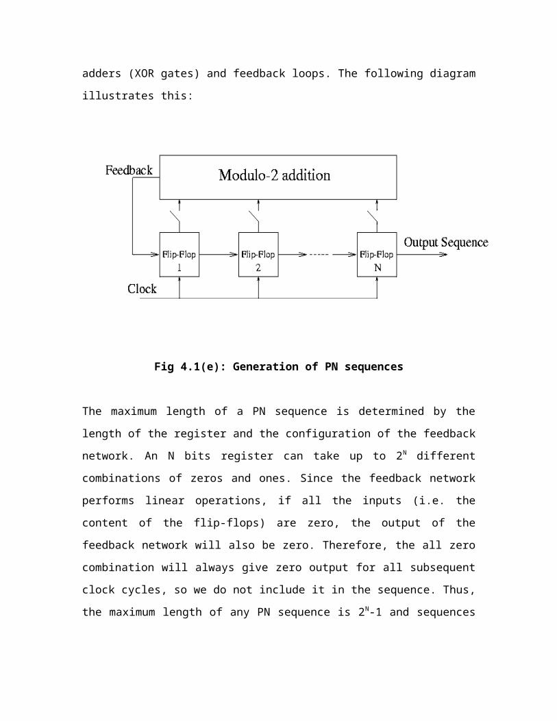
using shift registers, modulo-2 adders (XOR gates) and feedback loops.
So far we haven't discussed what properties we would want the spreading signal to have.
This depends on the type of system we want to implement. Let's first consider a system
where we want to use spread spectrum to avoid jamming or narrow band interference.
If we want the signal to overcome narrow band interference, the spreading function needs
to behave like noise. Random binary sequences are such functions. They have the
following important properties:
Balanced: they have an equal number of 1's and 0's
Single Peak auto-correlation function
Carrier 1
Carrier n
Impulse modulatori/p Binary
Sequence
P.N sequence
Wave shaping
filter
Page 35
In fact, the auto-correlation function of a random binary sequence is a triangular
waveform as in the following figure, where TC is the period of one chip:
Fig 4.1(d): Auto-correlation function
Hence the spectral density of such a waveform is a sinc function squared, with first zeros
at ± 1/TC
PN sequences are periodic sequences that have a noise like behavior. They are generated
using shift registers, modulo-2 adders (XOR gates) and feedback loops. The following
diagram illustrates this:
Page 36
Fig 4.1(e): Generation of PN sequences
The maximum length of a PN sequence is determined by the length of the register and the
configuration of the feedback network. An N bits register can take up to 2N different
combinations of zeros and ones. Since the feedback network performs linear operations,
if all the inputs (i.e. the content of the flip-flops) are zero, the output of the feedback
network will also be zero. Therefore, the all zero combination will always give zero
output for all subsequent clock cycles, so we do not include it in the sequence. Thus, the
maximum length of any PN sequence is 2N-1 and sequences of that length are called
Maximum-Length Sequences or m-sequences.
Impulse Modulator: It is used to modulate the impulse train coming from the multiplier,
where the energy per chip is E.
Wave shaping filter: This filter is used to modify the shape of the waveform i.e., it is used
to adjust the energy levels of the waveform before the sequence modulates the multiple
carriers.
4.1.2 CHANNEL:
The channel is assumed to be a slowly varying frequency selective Rayleigh channel with
delay spread of Tm In order to facilitate a performance comparison between a single-
carrier RAKE system and the proposed multicarrier system, we define two channel
models; one is a time domain model for a RAKE system, and the other is a frequency
domain model for a multicarrier system. For a single-carrier system, the key parameter is
the number of resolvable paths of the channel, L1, which is given by
………… (4)
Page 37
Then the complex lowpass equivalent impulse response of the channel can be modeled as
……….. (5)
where is a zero-mean, complex Gaussian random variable. On the other hand, a
frequency domain channel model can be characterized by the coherence bandwidth,
which is given below
……….. (6)
We are going to choose M so as to meet the following Conditions
……….. (7)
Each sub-band of a multicarrier system has no selectivity; all sub-bands are subject to
independent fading
………… (8)
From (3) and (6), these two conditions are satisfied if
……… (9)
Page 38
The received signal is then given by
………….. (10)
The receiver of the first user (k = 1) is shown in Fig. 2(b), n’=O where we assume the
following characteristics for the chip wave-shaping filter:
………. (11)
Satisfies the Nyquist criterion
The CDMA standard describes the processing performed in the terminal receiver as being
complementary to those of the base station modulation processes on the Forward CDMA
Channel". The input signal of the receiver is given to serial to parallel converter. The
signal out of the converter demodulates the multiple carrier signals so that each sequence
modulates an impulse train and pseudo-random spreading signature sequence are given
to multiplier. Now the outputs received are combined by using maximal ratio combiner.
Page 39
4.1.3 RECEIVER:
Fig 4.1(f): Block diagram of receiver
Serial to parallel converter: At the transmitter end N bits are sent simultaneously over
N sub-carriers. Each sub-carrier transmit different symbol with spreading code in time-
domain. In order to separate different symbol of each subscriber we use this converter.
Maximal ratio combiner: Maximal Ratio Combining is defined as all paths co-phased
and summed with optimal weighting to maximize combiner output SNR MRC is the
optimum linear combining technique for coherent reception with independent fading. Its
main advantage is the reduction of the probability of deep fades
Carrier 1
Carrier n
Low pass Impulse
modulator
Low pass Impulse
modulator
P.N sequence
P.N sequence
MaximalRatioCombiner
Received signal
Serial to parallel converter
Page 40
.
Fig 4.1(g): Maximal ratio combiner
………… (12)
Also, we assume that is bandlimited to W’, where
W’ is
…….. (13)
and fi is the ith carrier frequency. This implies that the DS waveforms do not overlap.
Page 41
CHAPTER 5
SOURCE CODE
function varargout = DSCDMA(varargin)
% DSCDMA M-file for DSCDMA.fig
% DSCDMA, by itself, creates a new DSCDMA or raises the existing
% singleton*.
%
% H = DSCDMA returns the handle to a new DSCDMA or the handle to
% the existing singleton*.
%
% DSCDMA('CALLBACK',hObject,eventData,handles,...) calls the local
% function named CALLBACK in DSCDMA.M with the given input arguments.
%
% DSCDMA('Property','Value',...) creates a new DSCDMA or raises the
% existing singleton*. Starting from the left, property value pairs are
% applied to the GUI before DSCDMA_OpeningFunction gets called. An
% unrecognized property name or invalid value makes property application
% stop. All inputs are passed to DSCDMA_OpeningFcn via varargin.
%
% *See GUI Options on GUIDE's Tools menu. Choose "GUI allows only one
% instance to run (singleton)".
%
% See also: GUIDE, GUIDATA, GUIHANDLES
% Copyright 2002-2003 The MathWorks, Inc.
Page 42
% Edit the above text to modify the response to help DSCDMA
% Last Modified by GUIDE v2.5 22-Mar-2009 13:32:56
% Begin initialization code - DO NOT EDIT
gui_Singleton = 1;
gui_State = struct('gui_Name', mfilename, ...
'gui_Singleton', gui_Singleton, ...
'gui_OpeningFcn', @DSCDMA_OpeningFcn, ...
'gui_OutputFcn', @DSCDMA_OutputFcn, ...
'gui_LayoutFcn', [] , ...
'gui_Callback', []);
if nargin && ischar(varargin{1})
gui_State.gui_Callback = str2func(varargin{1});
end
if nargout
[varargout{1:nargout}] = gui_mainfcn(gui_State, varargin{:});
else
gui_mainfcn(gui_State, varargin{:});
end
% End initialization code - DO NOT EDIT
% --- Executes just before DSCDMA is made visible.
function DSCDMA_OpeningFcn(hObject, eventdata, handles, varargin)
% This function has no output args, see OutputFcn.
% hObject handle to figure
% eventdata reserved - to be defined in a future version of MATLAB
% handles structure with handles and user data (see GUIDATA)
Page 43
% varargin command line arguments to DSCDMA (see VARARGIN)
% Choose default command line output for DSCDMA
handles.output = hObject;
global err
load err
% Update handles structure
guidata(hObject, handles);
% UIWAIT makes DSCDMA wait for user response (see UIRESUME)
% uiwait(handles.figure1);
% --- Outputs from this function are returned to the command line.
function varargout = DSCDMA_OutputFcn(hObject, eventdata, handles)
% varargout cell array for returning output args (see VARARGOUT);
% hObject handle to figure
% eventdata reserved - to be defined in a future version of MATLAB
% handles structure with handles and user data (see GUIDATA)
% Get default command line output from handles structure
varargout{1} = handles.output;
% --- Executes on button press in pushbutton1.
function pushbutton1_Callback(hObject, eventdata, handles)
% hObject handle to pushbutton1 (see GCBO)
% eventdata reserved - to be defined in a future version of MATLAB
% handles structure with handles and user data (see GUIDATA)
% ----------------------------------------------------------------------- %
snr_in_dB = 0:5:30;
Page 44
u = max_length([1 0 0 1 0 1]);
v = max_length([1 1 0 1 1 1]);
gold = mod(u+v,2);
sequence = gold;
M = 4; Nusers = 3;
for no = 1:Nusers
pn(no,:) = (-1).^sequence(no,:);
end;
h = zeros(1,M);
for path = 1:M
h(path) = randn+j*randn;
end;
err = [];
N = 100;
data = round(rand(N,Nusers));
err = cell(1);
nn = 1;
for i = 1:length(snr_in_dB)
[err_prob1 err_prob2] = errprob(data,snr_in_dB(i),M,pn,h);
end
% ----------------------------------------------------------------------- %
% Plot
err = err_prob1;
axes(handles.axes1)
err1 = err{1};
semilogy(snr_in_dB,err1,'r-+')
hold on
err2 = err{2};
semilogy(snr_in_dB,err2,'k-*')
hold on
err3 = err{3};
Page 45
semilogy(snr_in_dB,err3,'g-+')
hold on
err4 = err{4};
semilogy(snr_in_dB,err4,'c-*')
hold off
axis([0 30 0.000001 1])
grid on
legend('M = 1 N = 512','M = 2 N = 256','M = 3 N = 128','M = 4 N = 64')
xlabel('Eb/No(dB)')
ylabel('Probability of Bit Error')
%
***********************************************************************
%
PROBABILITY ERROR:
function [err avp n1] = errprob(data,snr_in_dB,M,pn,h)
% ----------------------------------------------------------------------- %
global err
snr = 10^(snr_in_dB/10);;
Nusers = 3;
N = 100;
Nc = 31;
T = 1;
Tc = (T/Nc);
%chip duration of MC-DS-CDMA
Nsample = 1; ts = Tc/Nsample;
fs = 1/ts;
%To save run time, we can select fc to be [1:M]*10000;
%To ensure that bandwidth of subcarrier doesn't overlap each other.
for i = 1:M
fc(i) = 10000+(1/(2*Tc));
Page 46
end;
error = 0;
iteration = 2;
for n = 1:iteration
for i = 1:N,
%Sampling time
t = [(i-1)*T:ts:i*T-ts];
datat = data(i,:);
%Transmitter
trans = transmitter(datat,t,Nsample,Nc,pn,M,fc,Nusers);
E = sum(trans.^2);
simga = sqrt(E/snr);
%For multicarrier system
hno=(randn(1,Nc)+j*randn(1,Nc));
for path = 1:M
noise = simga*hno;
rec(path,:) = conv(h(path),trans)+noise;
end;
%Receiver
z = multirece(rec,h,t,Nsample,Nc,pn,M,fc,Nusers);
%decision
if z(1)<1
decision = 0;
else
decision = 1;
end;
if decision ~= datat(1)
error = error+1;
end;
end;
Page 47
p(n) = error/(Nusers*N);
end;
avp = sum(p(n))/iteration;
% ----------------------------------------------------------------------- %
FILTER:
function [g_T] = Fil_ter(N,T,alpha,Fs,fc)
% ----------------------------------------------------------------------- %
n = -(N-1)/2:1:(N-1)/2;
for k = 1:1:length(n)
g_T(k) = 0;
for m = -(N-1)/2:1:(N-1)/2,
g_T(k) = g_T(k)+sqrt(RCF(Fs*m/(N),alpha,T,fc))*exp((j*2*pi*m*n(k)/N));
end
end
g_T = real(g_T);
g_T = g_T/max(abs(g_T));
% ----------------------------------------------------------------------- %
MAXIMUM LENGTH:
function [seq] = max_length(connection);
% ----------------------------------------------------------------------- %
connection = fliplr(connection);
% number of registers
m = length(connection)-1;
% length of sequences
L = 2^m-1;
%initial condition
register = [zeros(1,m-1),1];
Page 48
initial = register;
seq(1) = register(1);
for i=2:L
for j=1:m-1,
new_reg_cont(j) = register(j+1);
end;
new_reg_cont(m) = register(1);
for k=2:m
new_reg_cont(m) = new_reg_cont(m)+register(k)*connection(k);
new_reg_cont(m) = mod(new_reg_cont(m),2);
end;
register = new_reg_cont;
seq(i) = register(1);
if (initial==register)
disp('the connection is not valid to generate maximum length sequences');
break
end
end
%find other all sequences
for a = 2:L
seq(a,:) = wshift('1D',seq(a-1,:),1);
end
% ----------------------------------------------------------------------- %
MULTIPLE RECEIVERS:
function [z]= multirece(rec,h,t,Nsample,Nc,pn,M,fc,Nusers)
% ----------------------------------------------------------------------- %
Nf = 31;
alpha = 0.5;
T = 1;
Tc = (T/Nc);
Page 49
Fs = Nsample/Tc;
%Multiplying multicarrier M
for a = 1:Nusers
for b = 1:M,
demod(b,:) = sqrt(2)*rec(a,:).*cos(2*pi*fc(b)*t);
[ht] = Fil_ter(Nf,Tc,alpha,Fs,0);
aa = conv(demod(b,:),ht);
filter_output(b,:) = aa(1+(Nf-1)/2:length(aa)-(Nf-1)/2);
%sampling
for k = 1:Nc,
rec1(b,k) = filter_output(b,((k-1)*Nsample+1));
end;
%despread
temp(b) = conj(h(b))*sum(rec1(b,:).*pn(1,:));
end;
y(a) = sum(real(temp));
end
z = y; %Decision
% ----------------------------------------------------------------------- %
RCF:
function [y] = RCF(f,alpha,T,fc)
% ----------------------------------------------------------------------- %
if (abs(f-fc) > ((1+alpha)/(2*T))),
y = 0;
elseif (abs(f-fc) > ((1-alpha)/(2*T))),
y = (T/2)*(1+cos((pi*T/alpha)*(abs(f-fc)-(1-alpha)/(2*T))));
else
y = T;
end
% ----------------------------------------------------------------------- %
TRANSMITTER:
Page 50
function [mc_cdma] = transmitter(data,t,Nsample,Nc,pn,M,fc,Nusers)
% ----------------------------------------------------------------------- %
Nf = 31;
alpha = 0.5;
T = 1;
Tc = (T/Nc);
Fs = Nsample/Tc;
for no=1:Nusers
repeated_data(no,:) = kron(data(no),ones(1,Nc));
dsss(no,:) = repeated_data(no,:).*pn(no,:);
[ht] = Fil_ter(Nf,Tc,alpha,Fs,0);
sampled_dsss(no,:) = kron(dsss(no,:),ones(1,Nsample));
a(no,:) = conv(sampled_dsss(no,:),ht);
filter_output(no,:) = a(1+(Nf-1)/2:length(a)-(Nf-1)/2);
for d = 1:M,
mod(d,:) = sqrt(2)*filter_output(no,:).*cos(2*pi*fc(d)*t);
end;
%transmitted_signal
trans(no,:) = sum(mod,1);
end;
mc_cdma = sum(trans,1);
% ----------------------------------------------------------------------- %
Page 51
CHAPTER 6
SIMULATION RESULT
Fig 6(a): simulation result
Page 52
The above figure shows the BER versus Eb/No for various values of M and N, where N
is the processing gain and M is the number of carriers. Note that M=1 is nothing but
Single carrier CDMA system. Here the performance of a multicarrier system will be the
same as that of a single-carrier system if M=1 i.e., the no of carriers is equal to one.
Simulation results show that single carrier system having high probability of BER as
compared to the multi-carrier DS-CDMA
Page 53
CHAPTER 7
CONCLUSION AND FUTURE SCOPE
7.1 CONCLUSION:
In Multi Carrier DS CDMA we discussed a new way of realizing a wideband CDMA
system. As shown above, the system has a narrowband interference suppression effect,
along with a robust-ness to multipath fading. As a consequence, this system might be
suitable for a CDMA overlay scheme as described. In a CDMA overlay system, DS SS
signals are overlaid onto existing narrowband microwave signals-as a consequence, to
obtain the best performance, it is necessary to eliminate interference from narrowband
users to CDMA users and vice versa. To reject the interference from a narrowband signal
to a CDMA signal, the narrowband interference suppression capability of this multi-
carrier system is useful. On the other hand, to eliminate the interference from the DS SS
signals to a narrowband user, one can just stop transmitting at those frequencies which
occupy the same spectrum as the narrowband user.
Simulation Results shows that MC-CDMA advantageous in terms of BER as compared to
the SC-CDMA.
7.2 FUTURE SCOPE:
Page 54
There is no interference from the CDMA signals to the existing microwave systems.
Thus, there is no need for either a narrowband suppression filter at the receiver or a notch
filter at the transmitter. We need to design a system to full fill the above requirement.
BIBLIOGRAPHY
BOOKS:
G. L. Turin, “Introduction to spread-spectrum antkultipath techniques and their
application to urban digital radio,” Proc. IEEE, vol. 68, Mar. 1980.
R. E. Ziemer and R. L. Peterson, Digital Communications and Spread Spectrum
Systems. New York Macmillan, 1985.
R. L. Pickholtz, D. L. Schilling, and L. B. Milstein, ‘Theory of spreadspectrum
communications-A tutorial,” IEEE Trans. Commun., vol. COM-30, no. 5, May
1982.
S. Kondo and L. B. Milstein, “Multicarrier CDMA system with cochanne1
interference cancellation,” in Proc. VTC ’94, Stockholm, Sweden, June 1994, pp.
164C-1644.
“Multicarrier DS CDMA systems in the presence of partial band interference,” in
Proc. MILCOM ’94, Fort Monmouth, NJ, Oct. 1994.
WEB SITES:
www.wikepedia.com www.atmel.com www.circuitcellar.com
Page 55
.APPENDIX A
INTRODUCTION TO MATLAB
MATLAB is a high-level language and interactive environment that enables to perform
computationally intensive tasks faster than with traditional programming languages such
as C, C++, and FORTRAN.
We can use MATLAB in a wide range of applications, including signal and image
processing, communications, control design, test and measurement, financial modeling
and analysis, and computational biology. Add-on toolboxes (collections of special-
purpose MATLAB functions, available separately) extend the MATLAB environment to
solve particular classes of problems in these application areas.
MATLAB provides a number of features for documenting and sharing the work. We can
integrate the MATLAB code with other languages and applications, and distribute the
MATLAB algorithms and applications.
WHAT IS MATLAB?
MATLAB is a high-performance language for technical computing. It integrates
computation, visualization, and programming in an easy-to-use environment where
Page 56
problems and solutions are expressed in familiar mathematical notation. Typical uses
include
1. Math and computation
2. Algorithm development
3. Data acquisition
4. Modeling, simulation, and prototyping
5. Data analysis, exploration, and visualization
6. Scientific and engineering graphics
7. Application development, including graphical user interface building.
MATLAB is an interactive system whose basic data element is an array that does not
require dimensioning. This allows you to solve many technical computing problems,
especially those with matrix and vector formulations, in a fraction of the time it would
take to write a program in a scalar non interactive language such as C or FORTRAN.
The name MATLAB stands for matrix laboratory. MATLAB was originally written to
provide easy access to matrix software developed by the LINPACK and EISPACK
projects. Today, MATLAB engines incorporate the LAPACK and BLAS libraries,
embedding the state of the art in software for matrix computation.
MATLAB has evolved over a period of years with input from many users. In university
environments, it is the standard instructional tool for introductory and advanced courses
in mathematics, engineering, and science. In industry, MATLAB is the tool of choice for
high-productivity research, development, and analysis.
MATLAB features a family of add-on application-specific solutions called toolboxes.
Very important to most users of MATLAB, toolboxes allow you to learn and apply
specialized technology. Toolboxes are comprehensive collections of MATLAB functions
(M-files) that extend the MATLAB environment to solve particular classes of problems.
Areas in which toolboxes are available include signal processing, control systems, neural
networks, fuzzy logic, wavelets, simulation, and many others.
Page 57
THE MATLAB SYSTEM:
The MATLAB system consists of five main parts:
DEVELOPMENT ENVIRONMENT:
This is the set of tools and facilities that help you use MATLAB functions and files.
Many of these tools are graphical user interfaces. It includes the MATLAB desktop and
Command Window, a command history, an editor and debugger, and browsers for
viewing help, the workspace, files, and the search path.
THE MATLAB MATHEMATICAL FUNCTION:
This is a vast collection of computational algorithms ranging from elementary functions
like sum, sine, cosine, and complex arithmetic, to more sophisticated functions like
matrix inverse, matrix eigen values, Bessel functions, and fast Fourier transforms.
THE MATLAB LANGUAGE:
This is a high-level matrix/array language with control flow statements, functions, data
structures, input/output, and object-oriented programming features. It allows both
"programming in the small" to rapidly create quick and dirty throw-away programs, and
"programming in the large" to create complete large and complex application programs.
GRAPHICS:
MATLAB has extensive facilities for displaying vectors and matrices as graphs, as well
as annotating and printing these graphs. It includes high-level functions for two-
dimensional and three-dimensional data visualization, image processing, animation, and
presentation graphics. It also includes low-level functions that allow you to fully
customize the appearance of graphics as well as to build complete graphical user
interfaces on your MATLAB applications.
Page 58
THE MATLAB APPLICATION PROGRAM INTERFACE (API):
This is a library that allows you to write C and Fortran programs that interact with
MATLAB. It includes facilities for calling routines from MATLAB (dynamic linking),
calling MATLAB as a computational engine, and for reading and writing MAT-files.
MATLAB WORKING ENVIRONMENT:
MATLAB DESKTOP:
Matlab Desktop is the main Matlab application window. The desktop contains five sub
windows, the command window, the workspace browser, the current directory window,
the command history window, and one or more figure windows, which are shown only
when the user displays a graphic.
The command window is where the user types MATLAB commands and expressions at
the prompt (>>) and where the output of those commands is displayed. MATLAB defines
the workspace as the set of variables that the user creates in a work session. The
workspace browser shows these variables and some information about them. Double
clicking on a variable in the workspace browser launches the Array Editor, which can be
used to obtain information and income instances edit certain properties of the variable.
The current Directory tab above the workspace tab shows the contents of the current
directory, whose path is shown in the current directory window. For example, in the
windows operating system the path might be as follows: C:\MATLAB\Work, indicating
that directory “work” is a subdirectory of the main directory “MATLAB”; WHICH IS
INSTALLED IN DRIVE C. clicking on the arrow in the current directory window shows
a list of recently used paths. Clicking on the button to the right of the window allows the
user to change the current directory.
MATLAB uses a search path to find M-files and other MATLAB related files, which are
organize in directories in the computer file system. Any file run in MATLAB must reside
in the current directory or in a directory that is on search path. By default, the files
Page 59
supplied with MATLAB and math works toolboxes are included in the search path. The
easiest way to see which directories are on the search path. The easiest way to see which
directories are soon the search paths, or to add or modify a search path, is to select set
path from the File menu the desktop, and then use the set path dialog box. It is good
practice to add any commonly used directories to the search path to avoid repeatedly
having the change the current directory.
The Command History Window contains a record of the commands a user has entered in
the command window, including both current and previous MATLAB sessions.
Previously entered MATLAB commands can be selected and re-executed from the
command history window by right clicking on a command or sequence of commands.
This action launches a menu from which to select various options in addition to executing
the commands. This is useful to select various options in addition to executing the
commands. This is a useful feature when experimenting with various commands in a
work session.
USING THE MATLAB EDITOR TO CREATE M-FILES:
The MATLAB editor is both a text editor specialized for creating M-files and a graphical
MATLAB debugger. The editor can appear in a window by itself, or it can be a sub
window in the desktop. M-files are denoted by the extension .m, as in pixelup.m. The
MATLAB editor window has numerous pull-down menus for tasks such as saving,
viewing, and debugging files. Because it performs some simple checks and also uses
color to differentiate between various elements of code, this text editor is recommended
as the tool of choice for writing and editing M-functions. To open the editor, type edit at
the prompt opens the M-file filename.m in an editor window, ready for editing. As noted
earlier, the file must be in the current directory, or in a directory in the search path.
GETTING HELP:
The principal way to get help online is to use the MATLAB help browser, opened as a
separate window either by clicking on the question mark symbol (?) on the desktop
toolbar, or by typing help browser at the prompt in the command window. The help
Page 60
Browser is a web browser integrated into the MATLAB desktop that displays a Hypertext
Markup Language (HTML) documents. The Help Browser consists of two panes, the
help navigator pane, used to find information, and the display pane, used to view the
information. Self-explanatory tabs other than navigator pane are used to perform a search.


![1 Reed-Muller Codes for Peak Power Control in …1010.0189v1 [cs.IT] 1 Oct 2010 1 Reed-Muller Codes for Peak Power Control in Multicarrier CDMA Nam Yul Yu Department of Electrical](https://static.documents.pub/doc/80x56/5aa3f9a67f8b9a436d8ee0af/1-reed-muller-codes-for-peak-power-control-in-10100189v1-csit-1-oct-2010.jpg)


