25
All Rights Reserved © Alcatel-Lucent 2007 Performance Studies on LTE Advanced in the Easy-C Project 19.06.2008 Andreas Weber, Alcatel Lucent Bell Labs

All Rights Reserved © Alcatel-Lucent 2007
Performance Studies on LTE Advanced in the Easy-C Project
19.06.2008
Andreas Weber, Alcatel Lucent Bell Labs

All Rights Reserved © Alcatel-Lucent 20082 | LTE System Simulation | June 2008
Agenda
1. Introduction
2. EASY C
3. LTE System Simulator
4. Results
5. Conclusions and Outlook

All Rights Reserved © Alcatel-Lucent 20083 | LTE System Simulation | June 2008
Introduction
EUTRAN (Evolved Universal Terrestrial Radio Access Network) also called
LTE (Long Term Evolution) is the upcoming standard for packet switched
based mobile communication
LTE physical layer is based on OFDMA in the DL and SC-FDMA in the UL
The scope of EASY C is beyond LTE -> “LTE Advanced”
EASY C field trials are accompanied by system simulations
Candidate algorithms shall be evaluated before the real system is
implemented
Accuracy of simulations can be evaluated by comparison with measurements

All Rights Reserved © Alcatel-Lucent 20084 | LTE System Simulation | June 2008
EASY C
Overview
EASY C Project topics / objectives
BMBF project
3 year project / start Q2/2007
Preparation of a new Standard: “LTE Advanced”
Focus on improved spectral efficiency, cell border throughput, fairness, and latency
Field trials with optimized MIMO algorithms
Project partners:

All Rights Reserved © Alcatel-Lucent 20085 | LTE System Simulation | June 2008
EASY C
Field Trial Phasing
Step 1: Basic LTE Release 8 system
SU-MIMO
MU-MIM0 in UL
Step 2: Enhancements above Release 8
Remote Radio Heads
Enhanced receivers
Optimized codebooks
Beam Forming
MU-MIMO in DL
Step 3: Collaborative MIMO Schemes
Network MIMO
Cooperative scheduling
Interference coordination
All Rights Reserved © Alcatel-Lucent 20086 | LTE System Simulation | June 2008
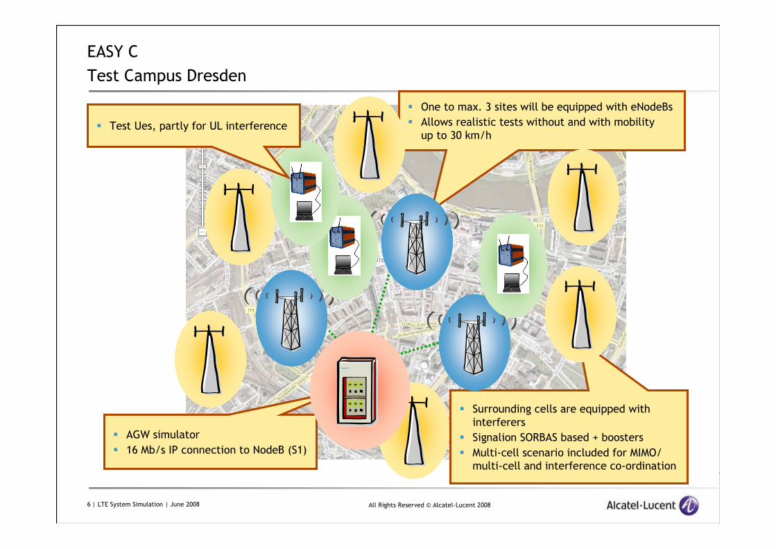
EASY C
Test Campus Dresden
One to max. 3 sites will be equipped with eNodeBs
Allows realistic tests without and with mobility
up to 30 km/h
Surrounding cells are equipped with
interferers
Signalion SORBAS based + boosters
Multi-cell scenario included for MIMO/
multi-cell and interference co-ordination
AGW simulator
16 Mb/s IP connection to NodeB (S1)
Test Ues, partly for UL interference

All Rights Reserved © Alcatel-Lucent 20087 | LTE System Simulation | June 2008
EASY C
System Simulation Approach
Field tests shall be accompanied by system simulations
Evaluation of candidate algorithms
Evaluation of accuracy of simulation models
System Simulations shall be 3GPP/NGMN compliant (TR 25.814, R1-070674)
Full simulation of interference
Wrap around
Spatial channel model
Full buffer simulation
Results shall be realistic (channel estimation loss model, ...)
First phase: Calibration of simulators of different partners (1x2 in DL and UL)
Second phase: Reference model results (2x2 in DL, 1x2 in UL)
Spectral Efficiency
User throughput CDF, fairness
Cell border throughput
Third phase:
Simulation of algorithms
Substitution of spatial channel model with
– ray tracing data
– channel measurements

All Rights Reserved © Alcatel-Lucent 20088 | LTE System Simulation | June 2008
LTE System Simulator
Objectives
Evaluation of LTE system performance in UL and DL
Antenna systems
– 2x2, 4x2, 4x4, ...
– correlated antennas
– uncorrelated antennas
– mixture of correlated and uncorrelated antennas
Algorithms
– Scheduler
– Link Adaptation
– Interference Coordination
Combination of performance enhancing technologies
Optimization of algorithms that are impacted by spatial channel behavior

All Rights Reserved © Alcatel-Lucent 20089 | LTE System Simulation | June 2008
LTE System Simulator
Reminder: DL LTE Channel Structure
t
f
Physical Resource Block (PRB)
14 OFDM Symbols x 12 Subcarrier
first 1...3 OFDM Symbols reserved for L1-L2-Signaling
one OFDM symbol
Subcarrier
Resource Element
Slot (0.5 ms)
Subframe (1 ms)
Slot (0.5 ms)
15 kHz
PRB
7515
5010
10020
255
61.4
Nr. PRBBW [MHz]

All Rights Reserved © Alcatel-Lucent 200810 | LTE System Simulation | June 2008
LTE System Simulator
Detailed Features
Features
Spatial channel model (WiM, Winner Model) generates spatial fast fading
Full simulation of interference, i.e. SCM is used for all channels
Event driven simulation on resource element basis, i.e. per subcarrier (in
frequency) and per OFDM symbol (in time), lower granularity possible
Monte Carlo drops in order to get a quicker randomization of mobile positions
(during drop path loss and shadowing is kept constant)
Link to system interface based on MIESM (Mutual Information Effective SINR
Mapping)
Receiver is explicitly modeled (MMSE or MRC)
1x1, 1x2, 2x2, 4x2, 4x4 TX/RX antennas
Single and multiple stream transmissions (e.g. PARC and SDMA)
Switching between single stream and multiple stream transmission

All Rights Reserved © Alcatel-Lucent 200811 | LTE System Simulation | June 2008
LTE System Simulator
Detailed Features
Features (continued)
Frequency selective and diverse allocation
Different schedulers
CQI generation, CQI reporting delay, CQI reporting period, CQI filtering
Ideal and realistic link adaptation
Asynchronous, adaptive HARQ (DL) and synchronous HARQ (UL) with feedback delay
Transport blocks consisting of an arbitrary number of PRBs
BLER calculation on transport block basis (with chase combining and IR)
Signaling overhead
Pilot symbol patterns (for 1, 2, 3, and 4 antennas)
Full and soft fractional frequency reuse
Large number of measurement values

All Rights Reserved © Alcatel-Lucent 200812 | LTE System Simulation | June 2008
LTE System Simulator
Spatial Channel Model
BSθ
AoDn,δ
, ,n m AoD∆
AoDmn ,,θ
BSΩ
N
NCluster n
AoAmn ,,θ
, ,n m AoA∆
,n AoAδ
MSΩ
MSθ
θv
BS array broadside
MS array broadside
BS array
MS direction
of travel
MS array
Subpath m
v
Example: urban macro: 6 paths with 20 subpaths each
source: 3GPP TR 25.996

All Rights Reserved © Alcatel-Lucent 200813 | LTE System Simulation | June 2008
LTE System Simulator
Fast Fading for OFDM
0 0.2 0.4 0.6 0.8 1 1.2 1.4 1.6
OFDM Relative Receive Signal Level
Veh B
0 20
40 60
80 100
120
subcarrier
0 10 20 30 40 50 60 70 80 90 100
time [5ms]
0 0.2 0.4 0.6 0.8
1 1.2 1.4 1.6
relative amplituderelative Amplitude
OFDM receive signal

All Rights Reserved © Alcatel-Lucent 200814 | LTE System Simulation | June 2008
LTE System Simulator
SINR over Frequency and Time

All Rights Reserved © Alcatel-Lucent 200815 | LTE System Simulation | June 2008
LTE System Simulator
Wrap Around
Wrap Around avoids
border effects
every BTS has six
mirrors
every mobile claims
to be in the middle of
2 rings of BTS sites
Mirror 1Mirror 2
Mirror 3
Mirror 4Mirror 5
Mirror 6

All Rights Reserved © Alcatel-Lucent 200816 | LTE System Simulation | June 2008
LTE System Simulator
Wrap Around

All Rights Reserved © Alcatel-Lucent 200817 | LTE System Simulation | June 2008
LTE System Simulator
Wrap Around in case of Frequency Reuse
Border effects with wrap
around if reuse factor is
not divisor of the number
of cells
Solution: Simulation with
21 sectors or restriction of
evaluation to inner
cells
All Rights Reserved © Alcatel-Lucent 200818 | LTE System Simulation | June 2008
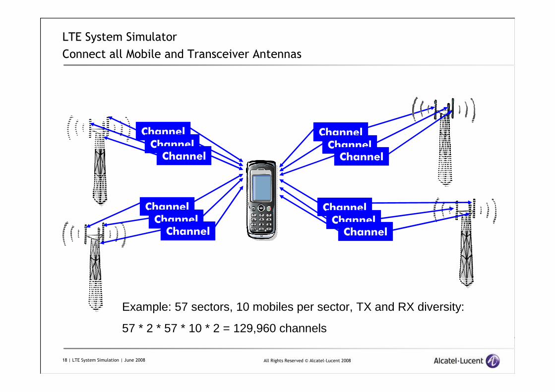
LTE System Simulator
Connect all Mobile and Transceiver Antennas
Channel
ChannelChannel
Channel
ChannelChannel
Channel
ChannelChannel
Channel
ChannelChannel
Example: 57 sectors, 10 mobiles per sector, TX and RX diversity:
57 * 2 * 57 * 10 * 2 = 129,960 channels

All Rights Reserved © Alcatel-Lucent 200819 | LTE System Simulation | June 2008
Results
Calibration: Geometry (exemplary)
User Geometry CDF
0.0
0.1
0.2
0.3
0.4
0.5
0.6
0.7
0.8
0.9
1.0
-10 -5 0 5 10 15 20
Wideband SINR [dB]
Cu
mu
lativ
e P
rob
abili
ty
21 sectors, 500m ISD
21 sectors, 1732 m ISD
57 sectors, 500 m ISD
57 sectors, 1732 m ISD
User Geometry = E[S]/(E[I] + R*N)
S = Signal Level, I = Interference Level, R = Receiver Noise Figure

All Rights Reserved © Alcatel-Lucent 200820 | LTE System Simulation | June 2008
Results
Reference Simulations: Exemplary resultsDOWNLINKAntenna Configuration
Inter Site Distance [m]
Spectral Efficiency [bits/s/Hz]
5-Percentile of UE Throughput [kbit/s]
1x2 1732 1.28 2041x2 500 1.38 3242x2 1732 1.37 2552x2 500 1.46 345
UPLINK*Antenna Configuration
Inter Site Distance [m]
Spectral Efficiency [bits/s/Hz]
5-Percentile of UE Throughput [kbit/s]
1x2 500 0.97 2951x2 1732 0.85 57wi thout IoT control -> high spectral effic iency , low edge user throughput

All Rights Reserved © Alcatel-Lucent 200821 | LTE System Simulation | June 2008
Results
Step 2 Candidate: Adaptive 4x2 SU-MIMO
SINR
UE velocity
low high
low
high
Polarisation beams
+ Closed-loop Tx
diversity
Polarisation beams +
Spatial Multiplexing
Polarisation beams
+ Alamouti
A
B
C
λ/2

All Rights Reserved © Alcatel-Lucent 200822 | LTE System Simulation | June 2008
Results
Step 2 Candidate: Adaptive 4x2 SU-MIMO
Comparison of different Antenna Systems and Precoding Matrices,500m ISD
0
100
200
300
400
500
600
1.0 1.1 1.2 1.3 1.4 1.5 1.6 1.7 1.8 1.9 2.0
Spectral Efficiency [bit/s/Hz/sector]
Cel
l B
ord
er T
hro
ug
hp
ut
[kb
it/s
]
500 1x1 Single Antenna TX
500 1x2 Single Antenna TX
500 2x2 CL TX Div & PSRC (36.211)
500 4x2 CL TX Div & PSRC (36.211)
500 4x2 Directional CL TX Div & PARC, 4 Beams, 4 Weights
500 4x2 Directional CL TX Div & PARC, 16 Beam, 8 Weights
1x1
1x2
2x2
4x2
optimized codebook
36.211 codebook

All Rights Reserved © Alcatel-Lucent 200823 | LTE System Simulation | June 2008
Results
Step 2 Candidate: Adaptive 4x2 SU-MIMO
Comparison of different Antenna Systems and Precoding Matrices,500m and 1732 m ISD
0
100
200
300
400
500
600
1.0 1.1 1.2 1.3 1.4 1.5 1.6 1.7 1.8 1.9 2.0
Spectral Efficiency [bit/s/Hz/sector]
Cel
l B
ord
er T
hro
ug
hp
ut
[kb
it/s
]500 1x1 Single Antenna TX
500 1x2 Single Antenna TX
500 2x2 CL TX Div & PSRC (36.211)
500 4x2 CL TX Div & PSRC (36.211)
500 4x2 Directional CL TX Div & PARC, 4 Beams, 4 Weights
500 4x2 Directional CL TX Div & PARC, 16 Beam, 8 Weights1732 1x1 Single Antenna TX
1732 1x2 Single Antenna TX
1732 2x2 CL TX Div & PSRC (36.211)1732 4x2 CL TX Div & PSRC (36.211)
1732 4x2 Directional CL TX Div & PARC, 4 Beams, 4 Weights
1732 4x2 Directional CL TX Div & PARC, 16 Beam, 8 Weights
1x1
1x2
2x2
4x2
All Rights Reserved © Alcatel-Lucent 200824 | LTE System Simulation | June 2008
Conclusions and Outlook
Conclusions
System simulations have been performed that show the benefits of
candidate algorithms for LTE Advanced
The results are based on an accurate simulator that includes models for the
spatial channel behavior
Parts of the receiver have to be modeled in the system simulator; a huge
number of channels has to be simulated -> computing time saving
programming is essential
Outlook
Many more sophisticated algorithms wait for their simulative evaluation
Channel measurements allow the evaluation of the accuracy of the ray
tracing data and spatial channel models
System simulations will be based on ray tracing data and channel
measurements –> possibility to compare field test and simulation results

All Rights Reserved © Alcatel-Lucent 200825 | LTE System Simulation | June 2008
www.alcatel-lucent.com


