28
Performance Test Methodology for EtherNet/IP Devices Version 1.0 March 14, 2005 PUB00081R1 Published by EtherNet/IP Implementors Workshop ODVA

Performance Test Methodology for EtherNet/IP Devices
Version 1.0 March 14, 2005 PUB00081R1
Published by EtherNet/IP Implementors Workshop
ODVA

Performance Test Methodology for EtherNet/IP Devices
March 14, 2005 ii PUB00081R1
Document Revision Log
Revision Section Remarks Date Author(s) 0.6 Initial Draft 8/10/04 EtherNet/IP
Performance Workgroup
0.6 Various Minor English edits 8/11/04 James Gilsinn 0.7 First draft sent to Implementors
Workshop for comments 9/16/04 James Gilsinn
0.8 Various Incorporated comments from Implementors Workshop participants
12/01/04 James Gilsinn
0.9 Various Updated document per recommendations from EtherNet/IP Performance Workgroup.
02/01/05 James Gilsinn
1.0 Various Final updates for first published version.
03/14/05 James Gilsinn

Performance Test Methodology for EtherNet/IP Devices
March 14, 2005 1 PUB00081R1
Abstract This document discusses and defines a number of test methodologies that are used in describing the performance of EtherNet/IP devices. Many of the terms and definitions used in this document are defined in other documents referred to in this document. This document is a product of the EtherNet/IP Performance Workgroup of the Open DeviceNet Vendor Association (ODVA) EtherNet/IP Implementors Workshop.
Table of Contents 1 Introduction .......................................................................................................2
1.1 Tests to be run................................................................................................................. 2 1.2 Evaluating the results...................................................................................................... 2 1.3 Requirements .................................................................................................................. 2
2 Test Setup...........................................................................................................3 2.1 Test Equipment Layout................................................................................................... 3 2.2 Performance of Test & Network Infrastructure Equipment ........................................... 3 2.3 User Programming .......................................................................................................... 4 2.4 DUT Setup ...................................................................................................................... 4
3 Test Descriptions ...............................................................................................4 3.1 Test (Definition Format) ................................................................................................. 4 3.2 Unloaded Cyclic/API Jitter Test ..................................................................................... 4 3.3 Loaded Cyclic/API Jitter Test......................................................................................... 8
3.3.1 Vary All Connection API, Maintain Total Throughput.......................................... 8 3.3.2 Vary Individual Connection API ............................................................................ 9 3.3.3 Inject Broadcast Traffic .......................................................................................... 9 3.3.4 Inject Spurious Multicast Traffic .......................................................................... 10 3.3.5 Maintain I/O Connections, Rapid TCP/IP Connections ....................................... 11 3.3.6 Maintain I/O Connections, TCP/IP Bandwidth .................................................... 11 3.3.7 Maintain I/O Connections, Total TCP/IP connections ......................................... 12
3.4 Response Latency Test ................................................................................................. 13 3.5 Action Latency.............................................................................................................. 14
3.5.1 Action Latency Single Output Frequency (AL-SOF) Test ................................... 14 3.5.2 Action Latency Loop-Back (AL-LB) Test ........................................................... 17
4 EtherNet/IP Performance Workgroup Members ........................................20 5 Ackowledgments..............................................................................................20 6 References ........................................................................................................20 Appendix A Test Architecture Categories ........................................................21
A.1 Simple Test ................................................................................................................... 21 A.2 Multiple Test Equipment Devices (Networked) ........................................................... 21 A.3 Multiple Test Equipment Devices (Generic) ................................................................ 22 A.4 Multiple Network Infrastructure Equipment Devices................................................... 22 A.5 Multiple Test and Network Infrastructure Equipment Devices.................................... 23
Appendix B Message Classes..............................................................................24 B.1 Basic Message Structure ............................................................................................... 24 B.2 ARP Request................................................................................................................. 25

Performance Test Methodology for EtherNet/IP Devices
March 14, 2005 2 PUB00081R1
B.3 EtherNet/IP ListIdentity Message................................................................................. 25 Appendix C Calculating a Statistically Significant Number of Samples .......26
1 Introduction The specifications used to define the performance characteristics of network devices are often written in different ways from different vendors. This makes it difficult for users to compare similar devices from without doing painstaking searching through manuals or hours contacting engineers from the vendors to determine how the different performance characteristics relate. This document defines a specific set of tests that vendors can use to measure and report the performance characteristics of EtherNet/IP devices. The results of these tests will provide the user comparable data from different vendors with which to evaluate these devices. [2] A previous document, “Performance Terminology for EtherNet/IP Devices” [1], defined many of the terms that are used in this document. The terminology document should be consulted before attempting to make use of this document.
1.1 Tests to be run There are a number of tests described in this document. Not all of the tests apply to all types of devices under test (DUTs). Vendors should perform all of the tests that can be supported by a specific type of product. An attempt has been made in writing this document to indicate what tests apply to what types of devices. These are only recommendations. Any additional performance tests that can be run on a particular DUT should be performed. The current version of this document only specifies performance tests that apply to CIP Class 1 connections. These connections are the main method used to transport real-time messages between multiple EtherNet/IP devices. In the future, these tests may be expended upon to include other connected and unconnected network performance tests.
1.2 Evaluating the results Performing all of the recommended tests will result in a great deal of data. Much of this data will not apply to the evaluation of the devices under each circumstance. Evaluating even that data which is relevant to a particular network installation will require experience which may not be readily available. Furthermore, selection of the tests to be run and evaluation of the test data must be done with an understanding of generally accepted testing practices regarding repeatability, variance and statistical significance of small numbers of trials. [3]
1.3 Requirements In this document, the words that are used to define the significance of each particular requirement are capitalized. These words are:
• MUST: This word or the words REQUIRED and SHALL mean that the item is an absolute requirement of the specification.
• RECOMMEND: This word or the adjective SHOULD means that there may exist valid reasons in particular circumstances to ignore this item, but the full implications should be understood and the case carefully weighed before choosing a different course.
• MAY: This word or the adjective OPTIONAL means that this item is truly optional. One vendor may choose to include the item because a particular marketplace requires it

Performance Test Methodology for EtherNet/IP Devices
March 14, 2005 3 PUB00081R1
or because it enhances the product, for example; another vendor may omit the same item.
An implementation of these performance tests that satisfies all the MUST and all the SHOULD requirements is said to be “unconditionally complete”. An implementation of these performance tests that satisfies all the MUST requirements but not all the SHOULD requirements is said to be “conditionally complete”. If an implementation of these performance tests fails to satisfy one or more of the MUST requirements, then it is considered “incomplete”. [3]
2 Test Setup 2.1 Test Equipment Layout A basic layout of the test architecture is shown below in Figure 1. The layout shown in Figure 1 is only the most basic type of test architecture. More complex layouts are shown in Appendix A, Test Architecture Categories that have additional test equipment devices and network infrastructure devices, some connecting directly to the DUT. When conducting a performance test, a description of the layout MUST be given along with a description of the different devices used in the test. When selecting a test architecture layout, references MAY be made to the layouts shown in the Appendix of this document as long as the devices taking part in the test are all identified and any special settings or programs recorded.
2.2 Performance of Test & Network Infrastructure Equipment It is RECOMMENDED that the fewest number of test equipment and network infrastructure equipment devices be used to minimize the complexity of the test and to reduce the affect that their errors play on the test results. Before conducting any test on the DUT, the performance of the test and network infrastructure equipment MUST be understood. If the test equipment is another industrial device, that device MUST be characterized by the appropriate EtherNet/IP performance tests before running the test on the DUT. If the test equipment is another type of device, any available performance characteristics MUST be recorded along with the test results. For network infrastructure equipment, the device performance based on the appropriate IETF RFC documents MUST be determined. These test results may be available from the manufacturer of the network infrastructure device. If so, the data should be obtained and filed along with the DUT’s performance test results. If not, the appropriate RFC tests MUST be conducted and the results filed along with the DUT’s performance test results. The final report on the DUT’s performance SHALL include notes indicating the test and network infrastructure equipment performance test results, but is NOT REQUIRED to include the actual performance test results themselves.
Network InfrastructureEquipment
TestEquipment
(TE)
DeviceUnder Test
(DUT)
Figure 1 - Basic Test Architecture

Performance Test Methodology for EtherNet/IP Devices
March 14, 2005 4 PUB00081R1
2.3 User Programming While testing EtherNet/IP devices, it MAY be necessary to use user level programming on any or all of the devices involved in the test. One example of these user level programs might be a ladder logic program on the DUT required to process input signals and produce a network packet. Another example may be special packets constructed on a packet generator to stimulate a response from the DUT. These programs MUST be documented along with the test results. It is RECOMMENDED that the user level programs be minimized in both length and complexity as to have the smallest affect on the performance of the devices.
2.4 DUT Setup Before beginning a performance test, the DUT MUST be configured as per the instructions provided by the vendor. Specifically, any special instructions or user level programming MUST be followed when preparing the test. The DUT setup MAY change for different tests, although it MUST remain consistent for each trial of the test. For example, ladder logic program 1 may be necessary to perform the Unloaded Cyclic/API Jitter Test, but ladder logic program 2 may be necessary to perform the Response Latency Test. The extra functionality in program 2 might affect the performance results measured while performing the Unloaded Cyclic/API Jitter Test, so it is not included in ladder logic program 1. Another example may be that the DUT requires a different hardware configuration to perform the Action Latency Single Output Frequency (AL-SOF) Test versus the Action Latency Loop-Back (AL-LB) Test. The hardware configuration MUST be maintained while performing each trial of the Action Latency Single Output Frequency (AL-SOF) Test, but it can be changed before performing the Action Latency Loop-Back (AL-LB) Test.
3 Test Descriptions 3.1 Test (Definition Format)
Objective: A basic description of the purpose for the test.
Procedure: A full description of the test methodology.
Reporting Format: A description of how the data is calculated and reported.
Devices Subject To Test: A list of some devices subject to this test. This list may not be complete but gives the testing personnel an idea of what devices may be covered by the test.
3.2 Unloaded Cyclic/API Jitter Test
Objective: Determine the cyclic/Accepted Packet Interval (API) jitter of the DUT.
Procedure: The producer/consumer model for EtherNet/IP allows multiple modes of communication to be chosen for real-time data exchange. [4] The most common

Performance Test Methodology for EtherNet/IP Devices
March 14, 2005 5 PUB00081R1
mode for producing data is called cyclic production. During cyclic production, the producer will try to send data at a particular rate called the Requested Packet Interval (RPI). The RPI and corresponding API dictates the speed of the data produced over the network regardless of the rate at which the actual data values change. The other modes of producing data are polled and change-of-state. For polled data, one device explicitly asks another device for a particular piece of data. For talking between two devices, this is a simple way to accomplish data exchange, but when the same information needs to go to many different devices, there is a large amount of extra communication. The last mode of producing data is called change-of-state. This means that one device only sends data to another device when a change in the value occurs. This can easily reduce network traffic, but may lead to problems since the receiving device does not know if the producing device has nothing new to report or if it is still active. EtherNet/IP does not implement a pure form of change-of-state, but a modified version that still sends out some data at regular intervals to maintain this “heartbeat” signal going to the receivers. Since the API is the basis for most of the real-time I/O communications over EtherNet/IP, it is a natural place to start when looking at device performance. The ability for a device to maintain that API value under different conditions may be very important to the control system. No device will perform perfectly, so these tests will show how closely a particular device is able to maintain the API value. They will not determine a pass or fail value. That will have to be determined by the user and whether the device’s performance characteristics meet the application’s needs. The basic premise of the cyclic/API tests will be to determine the maximum throughput of the device at a particular API value. Both producer and consumer devices will be tested. Devices will not be penalized for tests performed outside their published capabilities. The tests will result in a 2D matrix of maximum throughput versus API value. Pseudo-code for the test is shown below. Cyclic API Testing Pseudo-Code 1. Setup the RPI and Connection Size for the test 2. Establish a connection with the device under test (DUT) 3. Communicate with the DUT for some time 4. Check for packet loss 5. Calculate the API statistics (min, max, average, standard
deviation, histogram, etc.) 6. If there is packet loss, increase the RPI value (decrease
frequency) and continue 7. Else, report the API and statistics
Implementing this pseudo-code is relatively easy for testing producer devices. Any device can be used as a traffic generator to stimulate the packet generation by the DUT. This allows the network analyzer to remain a passive component in the test, as it is only required to listen to the packets produced by the DUT. By eliminating the
Performance Test Methodology for EtherNet/IP Devices
March 14, 2005 6 PUB00081R1
need to have the network analyzer perform steps 1 to 3, the error reported due to the network analyzer can be minimized. EtherNet/IP uses a sequence number in its protocol, so packet loss (or even out-of-sequence packets) in step 4 can be determined by following the sequence numbers that are produced by the DUT. The statistics calculated in step 5 relate to the throughput at the selected API and jitter in the throughput value. If the test shows no packet loss then the test is successful and the values are reported. Otherwise, the test needs to be re-run at a larger RPI value (lower RPI frequency). While the test implementation for producer devices is relatively simple, the implementation for consumer devices is more complicated. Consumer devices are expecting to receive packets at the API rate, and may not be able to report packet loss. This is because EtherNet/IP devices are not required to have two-way communications except for a heartbeat. Another difficulty is that the network analyzer should be responsible for the traffic generation in steps 1 to 3 or the other test equipment may introduce error with its own jitter. This error MUST be determined before conducting the test on the DUT by using the producer test described above. The only way to eliminate these types of errors would be to use the network analyzer as a traffic generator, which SHOULD have at least an order of magnitude more accurate timing than the DUT’s minimum RPI, to produce the data at regular intervals. [5] It is common for devices to support multiple EtherNet/IP I/O connections. In order to fully test the DUT’s performance, it SHOULD be tested using varying numbers of connections. As this is the unloaded or within-bounds test, the number, speed, and size of the connections should be within the manufacturer’s specifications. In order to present statistically significant results, a large number of packets SHOULD be produced or consumed by the DUT and a series of trials should be conducted (see Appendix C for more information on determining the number of packets for each trial). The large number of packets of data provides that each individual trial has a statistically large number of API times in order to calculate the standard deviation and histogram. Having multiple trials allows for statistical anomalies to be determined in case one test trial was not long enough to encounter them.
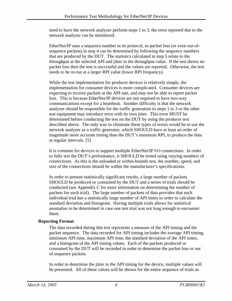
Reporting Format The data recorded during this test represents a measure of the API timing and the packet sequence. The data recorded for API timing includes the average API timing, minimum API time, maximum API time, the standard deviation of the API times, and a histogram of the API timing values. Each of the packets produced or consumed by the DUT will be recorded in order to determine the packet loss or out of sequence packets. In order to determine the jitter in the API timing for the device, multiple values will be presented. All of these values will be shown for the entire sequence of trials as

Performance Test Methodology for EtherNet/IP Devices
March 14, 2005 7 PUB00081R1
well as each individual trial. When making calculations on the entire sequence of trials, it is important to remember to include the number of points recorded during each individual trial. The average API value is the sum of the API values divided by the number of packets in the test. The worst case jitter will be calculated as the maximum API value minus the minimum API value. The standard jitter will be calculated as 2 standard deviations (one above and one below the average API). The histogram of jitter/variability will be reported as a graph of number of packets in each bin vs. API value bins. Equations:
∑=
⎟⎠⎞
⎜⎝⎛=
N
i
iAPI N
APIAverage1
APIAPIwc MINMAXJitter −=
APIstdJitter σ×= 2 Where: N = Number of Samples AverageAPI = Average API Measurement APIi = i’th API Measurement Jitterwc = Jitter, Worst Case Jitterstd = Jitter, Standard MAXAPI = Maximum API Measurement MINAPI = Minimum API Measurement ΣAPI = Standard Deviation of API Measurements Example Plot:
Example Cyclic Jitter Histogram
0
10
20
30
40
50
0 2 4 6 8 10 12 14 16 18 20Histogram Bins
Num
ber o
f Pac
kets
For tests involving multiple connections, the number, frame size, and speed of those connections MUST be noted in the results. The maximum throughput is calculated as the total number of frames produced or consumed multiplied by the speed at which those frames are produced or consumed. Example: Given a device can support 4 unidirectional connections @ 10ms API and 8 unidirectional connections @ 50ms API all with a frame size of 128 bytes, the throughput of the device should be:

Performance Test Methodology for EtherNet/IP Devices
March 14, 2005 8 PUB00081R1
( ) ( )[ ] ( )( ) ( ) s
bitss
bytesframe
bytess
frames
framebytes
ThroughputmsframesmsframesThroughput
57344071680128@560
128@501810
14
===
×+×=
Devices Subject to Test Any EtherNet/IP device that produces or consumes data on a CIP class 1 connection.
3.3 Loaded Cyclic/API Jitter Test
Objective: Determine the affect of background traffic and other out-of-bounds conditions on the cyclic/API jitter of the DUT.
Procedure: Since many EtherNet/IP devices are built on platforms with limited resources, it is necessary to determine the affect of background traffic or other out-of-bounds conditions on the devices. The procedure for the loaded cyclic/API jitter test is very similar to the unloaded test, however the DUT will be asked to produce or consume data on a noisy network or outside its published specifications. The tests will be setup in a similar way to the one described in the unloaded test except that there may be additional hardware for background traffic generation during the tests. The following sections will describe the individual variations to be tested.
Reporting Format: In all the tests listed below, the performance of the I/O connections established MUST be reported in addition to the other values listed using the format shown above in the Unloaded Cyclic/API Jitter Test.
Devices subject to the tests: Any device subject to the Unloaded Cyclic/API Jitter Test SHOULD be tested for its loaded behavior as well.
3.3.1 Vary All Connection API, Maintain Total Throughput
Objective: Vary the number of connections, the speed of those connections, and/or the size of those connections, maintaining the theoretical total throughput and see the affect on the DUT.
Procedure: Keep the theoretical total throughput the same but vary the number of connections and the speed of those connections. Example: If the DUT’s total throughput is s
bitss
bytesframe
bytess
frames 57344071680128@560 == with 4 unidirectional connections @ 10ms API and 8 unidirectional connections @

Performance Test Methodology for EtherNet/IP Devices
March 14, 2005 9 PUB00081R1
50ms API, then try 5 unidirectional connections @ 10ms API and 3 unidirectional connections @ 50ms API, or 3 unidirectional connections @ 10ms API and 13 unidirectional connections @ 50ms API. See if the device is capable of supporting the number of unidirectional connections and/or maintaining the total throughput for the device.
Reporting Format: The report MUST indicate the number of connections that were established and the speed and size of those connections.
3.3.2 Vary Individual Connection API
Objective: Determine how the DUT reacts to higher or lower than the expected API for a particular connection.
Procedure: Establish one I/O connection to the DUT at the highest supported API frequency. Start communicating with the DUT using the given API frequency. Then either increase or decrease the frequency of the API without reestablishing the connection. The frequency of the API SHALL NOT be dropped below the timeout multiplier for the device. The traffic generator MUST be capable of changing the API frequency without reestablishing the CIP class 1 connection using the new API frequency. This rate change MAY be either a step function or a ramp, although the changes desired in this test are not large with respect to the API frequency. After testing the device with one connection, establish a fully loaded set of connections using the manufacturer’s specified number, size, and speed for those connections. Then vary one of the fastest connections as described above.
Reporting Format: The report MUST indicate not only the API’s tested and the ability of the DUT to handle the different frequencies, but SHOULD also indicate any overload behavior that the DUT experienced.
3.3.3 Inject Broadcast Traffic
Objective: Determine how the DUT reacts to broadcast traffic on the network.
Procedure: Establish a fully loaded set of I/O connections using the manufacturer’s specified number, size, and speed for those connections. First, inject layer 2 broadcast traffic (MAC Address FF:FF:FF:FF:FF:FF) on the test network and see how the device’s performance is affected. It is RECOMMENDED that these layer 2 broadcast messages be ARP request messages, since these will be the most likely layer 2 broadcast messages seen by the DUT. Then inject layer 3 broadcast traffic (IP Address 0.0.255.255 for a class B network) on the test network and see how the device’s performance is affected. In either case, the traffic generator MUST not

Performance Test Methodology for EtherNet/IP Devices
March 14, 2005 10 PUB00081R1
inject more than 1% (of theoretical network bandwidth) broadcast traffic on the network, and the network infrastructure equipment MUST not be configured to filter out broadcast traffic on the network.
Reporting Format: The report MUST indicate the types of broadcast messages used, any special formatting for the broadcast messages, and the amount of traffic generated in either percent utilization at a particular network speed or the total number of bits per second injected. The report MUST also indicate the performance degradation of the DUT, if any, and any overload behavior experienced by the DUT.
3.3.4 Inject Spurious Multicast Traffic
Objective: Determine how the DUT reacts to multicast traffic on the network.
Procedure: Since EtherNet/IP uses multicast IP for CIP class 1 messages, it is necessary to determine if the DUT suffers any performance degradation in the presence of other multicast traffic on the network. Establish a fully loaded set of I/O connections using the manufacturer’s specified number, size, and speed for those connections. Then, determine what Layer 3 multicast addresses are being used by the DUT for the established connections. First, inject multicast traffic on the network to the “All Systems” multicast address (224.0.0.1) that requires a response from the DUT. It is RECOMMENDED that this be a ListIdentity message, since all EtherNet/IP devices are required to support this message. Next, inject multicast traffic on the network to an IP address outside the range on EtherNet/IP addresses (239.192.0.0/14). Streaming video or other standard internet technologies may be capable of producing this background multicast traffic. Third, inject multicast traffic on the network to a multicast IP address already in use by the DUT but which uses a different EtherNet/IP Connection ID. This will force the device to filter out the extraneous multicast traffic above the IP layer. Fourth, inject multicast traffic on the network to a multicast IP address already in use by the DUT with the same EtherNet/IP Connection ID as an open connection, but a different sequence number. This may cause the device to experience an error.
Reporting Format: In all the cases listed above, the multicast addresses, open EtherNet/IP Connection IDs, and the injected EtherNet/IP Connection IDs MUST be reported along with the performance test results and any overload behavior experienced by the DUT.
Notes: EtherNet/IP requires that all devices react to the ListIdentity message, but it does not specify a rate at which these can occur before the device can fail. This test is part of the way this value can be determined. This test can also be used to possibly limit the frequency of the ListIdentity messages a device is required to react to before it starts throwing them away.

Performance Test Methodology for EtherNet/IP Devices
March 14, 2005 11 PUB00081R1
3.3.5 Maintain I/O Connections, Rapid TCP/IP Connections
Objective: Determine how the DUT reacts to directed TCP/IP traffic by establishing and closing TCP/IP connections quickly. This test is similar to maintaining I/O connections while performing a web page download from the DUT.
Procedure: Before conducting this test, determine whether the DUT is capable of supporting a fully loaded set of connections and still have resources to service additional TCP/IP requests. If the device is not capable of supporting a fully loaded set of I/O connections while maintaining the resources to service additional TCP/IP requests, then determine the maximum number of I/O connections that the device is capable of supporting. Establish a fully loaded set of I/O connections using either the manufacturer’s specified number, size, and speed for those connections or the number, size, and speed that the device can support while maintaining the resources to support additional TCP/IP requests. After starting the I/O connections, establish a TCP/IP connection to the device and then tear it down. Continue this process and monitor the speed at which the TCP/IP connections can be opened and closed. Programs like the DOS FTP tool “mget” and the Linux web retrieval tool “wget” may be able to perform this task if the device supports FTP.
Report Format: Report the total number of connections used for the test, the duration of the test, the speed at which the connections could be opened and closed, and any overload behaviors recorded.
Notes: In industrial devices, it is fairly common to do file upload/download/compare (UDC) via FTP sessions or webpage downloads via HTTP. These may mean doing file actions on one large file or a series of small files. This test establishes how the DUT will react to a large number of TCP traffic from many small TCP sessions, as in a webpage download, while still maintaining the I/O sessions.
3.3.6 Maintain I/O Connections, TCP/IP Bandwidth
Objective: Determine the affect of downloading or uploading information from or to the DUT has on its I/O performance. This test is similar to maintaining I/O connections while performing a file upload/download to or from the DUT.
Procedure: Before conducting this test, determine whether the DUT is capable of supporting a fully loaded set of connections and still have resources to service additional TCP/IP requests. If the device is not capable of supporting a fully loaded set of I/O connections while maintaining the resources to service additional TCP/IP requests, then determine the maximum number of I/O connections that the device is capable of

Performance Test Methodology for EtherNet/IP Devices
March 14, 2005 12 PUB00081R1
supporting. Establish a fully loaded set of I/O connections using either the manufacturer’s specified number, size, and speed for those connections or the number, size, and speed that the device can support while maintaining the resources to support additional TCP/IP requests. After starting the I/O connections, establish a TCP/IP connection to the device and download or upload large blocks of information from or to the DUT. Programs like the DOS FTP tool “mget *.*” or the Linux web retrieval tool “wget -R[ecursive]” may be able to perform this task if the device supports FTP.
Reporting Format: Report the total number of bytes of information downloaded or uploaded from or to the DUT, the duration of the test, and any overload behaviors recorded.
Notes: In industrial devices, it is fairly common to do file upload/download/compare (UDC) via FTP sessions or webpage downloads via HTTP. These may mean doing file actions on one large file or a series of small files. This test establishes how the DUT will react to a large amount of TCP traffic from a single TCP session, as in a large file UDC session, while still maintaining the I/O sessions.
3.3.7 Maintain I/O Connections, Total TCP/IP connections
Objective: Determine the affect that maintaining additional TCP/IP connections has on the DUT and determine the maximum number of connections the DUT supports.
Procedure: Before conducting this test, determine whether the DUT is capable of supporting a fully loaded set of connections and still have resources to service additional TCP/IP requests. If the device is not capable of supporting a fully loaded set of I/O connections while maintaining the resources to service additional TCP/IP requests, then determine the maximum number of I/O connections that the device is capable of supporting. Establish a fully loaded set of I/O connections using either the manufacturer’s specified number, size, and speed for those connections or the number, size, and speed that the device can support while maintaining the resources to support additional TCP/IP requests. After starting the I/O connections, begin establishing and maintaining additional TCP/IP connections with the DUT at a rate less than the rate determined in the rapid TCP/IP connections test described in Section 3.3.5. Continue establishing connections to the DUT until the maximum number of TCP/IP connections has been reached. Only after all the maximum number of connections is determined should all of the TCP/IP connections be torn down. A script involving programs like the DOS FTP tool “mget” and the Linux web retrieval tool “wget” should be capable of performing this task if the device supports FTP.
Performance Test Methodology for EtherNet/IP Devices
March 14, 2005 13 PUB00081R1
Reporting Format: Report the total number of connections opened with the DUT and any overload behaviors recorded.
3.4 Response Latency Test
Objective: Determine the latency associated with the DUT receiving a request for information from its memory and responding to that request.
Procedure: Response latency tests the ability of a device to respond to a request for information. The test will be used to determine the efficiency of the communications stack. Since the command and response will only be reading information from the device’s memory, there should be a minimum of processing overhead associated with the test results. For EtherNet/IP, the simplest response latency test would be to have the device return its identity object information. As the identity object is a specific EtherNet/IP and CIP concept, the command would have to be processed through the entire communications stack to the application layer. Other standard objects like the TCP/IP and Ethernet link object could also be selected, but the potential exists for devices to trick the test by responding at a lower level. Another test of the response latency would be to read data from an assembly object. But, the test procedure would have to be customized for each vendor and product, since assembly objects are not standard between devices. To read the identity object information from the DUT, the test equipment SHOULD send a ListIdentity message and waits back for a response from the DUT. It is RECOMMENDED that a multicast UDP message format with the destination address as 224.0.0.1 be used for the ListIdentity message when it is sent. This allows for the highest probability that the DUT will respond back given that all EtherNet/IP devices are required to service the ListIdentity message and that multicast UDP address. If the test layout involves more than one piece of test equipment, it is possible that the DUT will not be the only device to respond to the ListIdentity message. In that case, the test equipment MUST be capable of distinguishing between the multiple ListIdentity response messages. The Response Latency for the DUT is calculated as the time difference between the last bit of the ListIdentity message packet leaving the test equipment and the first bit of the response packet being received by the test equipment. This measurement will include latencies not directly associated with the DUT’s performance: wire latencies, network infrastructure latencies, test equipment latencies, etc. [5][6] These latencies can be estimated before a test is performed by using the network infrastructure tests as described in RFC 1242, 2544, 2285, and 2889, as well as others. [2][3][7][8] These estimated latencies MUST be reported with the test results so that they can be taken into account when analyzing the DUT’s performance.

Performance Test Methodology for EtherNet/IP Devices
March 14, 2005 14 PUB00081R1
Reporting Format The time delay between the last bit of the ListIdentity command being sent and the first bit of the response from the DUT being received SHALL be reported. If no response is received by the test equipment, then the report MUST reflect an error in the test and no value will be reported. In that case, the number of commands and responses SHALL be reported. A statistically large number of samples should be taken in order to calculate the response latency for the device.
Devices Subject To Test: All EtherNet/IP devices.
Notes: While all EtherNet/IP devices are required to respond to the ListIdentity message, the test setup will consist of a small enough number of devices that the total number of responses should be small (less than 10). This should not load down the network of the test equipment too much that it should affect the test results, but this will have to be determined during initial test development.
3.5 Action Latency Action latency tests the ability for a device to either cause or measure a physical action and determine the time between the action and the associated network packet. If the device is being commanded to act, it is the time between the device receiving the network packet and the action happening. If the device is producing data, it is the time between the physical action and the device sending the network packet. These tests will be highly device specific, and require application level programming on the part of the tester. These tests will also be affected by multiple error sources, since the test equipment may consist of more than one device.
3.5.1 Action Latency Single Output Frequency (AL-SOF) Test
Objective: Test the action latency of the DUT to process a command and create a physical output or receive a physical input and send a network response.
Procedure: The action latency single output frequency (AL-SOF) test determines the single direction action latency. For a DUT with an output, the test equipment stimulates the DUT to send a continuous, periodic physical output. For a DUT with an input, the
TE1 DUT
Network InfrastructureEquipment
TE2
…1……0……1……0……1…
Scope Trace
Hardwired
Figure 2 - Example AL-SOF Test Setup for a DUT with a Digital Output

Performance Test Methodology for EtherNet/IP Devices
March 14, 2005 15 PUB00081R1
test equipment stimulates the DUT to read a continuous, periodic physical input. The DUT hardware is setup with at least one test equipment device attached to the physical input or output of the DUT. This test equipment MUST be capable of analyzing the physical signal created by the DUT (like an oscilloscope), or providing a known physical input signal to the DUT (like a function generator). Since this test will use relatively low frequencies (ms), it is also possible to use a computer with a data acquisition or signal generator board. If the DUT has multiple inputs or multiple outputs all with the same specifications, it is acceptable to only test with one of the ports for this test. If the multiple inputs or outputs have different specifications, each group MUST be tested separately. Figure 2 shows an example of how a possible test setup may appear for a DUT with a digital output involved in an Action Latency Single Output Frequency (AL-SOF) Test. In this example, the traffic generator (TE1) would issue commands to the DUT to simulate a digital output square-wave signal. The frequency and any irregularities of the output signal from the DUT would be monitored by an oscilloscope (TE2). Any change in the frequency or any missed cycles would be apparent in the scope trace, and would relate to the performance of the DUT. The test equipment MUST establish a CIP class 1 connection to the DUT using the fastest possible API that the DUT supports. The connection SHOULD be established with real-time data flowing in at least the direction for the test. If performing the input AL-SOF test, then the real-time data should be flowing from the DUT to the test equipment. If performing the output AL-SOF test, then the real-time data SHOULD be flowing from the test equipment to the DUT. The other direction MUST maintain the connection properly with the DUT. Since the AL-SOF test is highly affected by the test equipment and the DUT, it is RECOMMENDED that the smallest code be used during the test. Many EtherNet/IP devices use ladder-logic, so this would mean limiting the number of rungs in the ladder program to reduce the processing overhead. During the output AL-SOF test, the test equipment sends a periodic signal to the DUT. For a digital output, the traffic generator SHOULD send a periodic square wave changing from low (0) to high (1) continuously for each RPI cycle. For an analog output, the traffic generator SHOULD send a periodic saw-tooth signal with a frequency no smaller than 10 times the API frequency. During the input AL-SOF test, the DUT receives a periodic signal from the test equipment and then sends the corresponding data value in a network packet. For a digital input, the test equipment SHOULD send a periodic square wave signal with a frequency set to the API cycle frequency. For an analog input, the test equipment SHOULD send a periodic saw-tooth signal with a frequency no smaller than 10 times the API frequency. In either case, the DUT MUST be configured to process the input signal and report the value in a network packet.
Performance Test Methodology for EtherNet/IP Devices
March 14, 2005 16 PUB00081R1
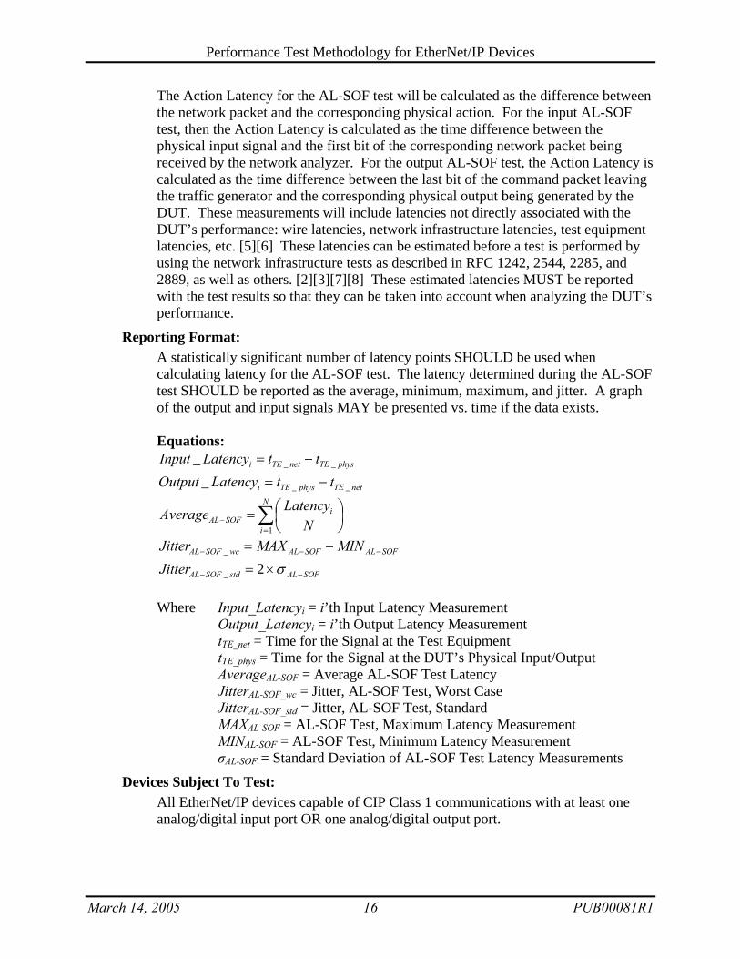
The Action Latency for the AL-SOF test will be calculated as the difference between the network packet and the corresponding physical action. For the input AL-SOF test, then the Action Latency is calculated as the time difference between the physical input signal and the first bit of the corresponding network packet being received by the network analyzer. For the output AL-SOF test, the Action Latency is calculated as the time difference between the last bit of the command packet leaving the traffic generator and the corresponding physical output being generated by the DUT. These measurements will include latencies not directly associated with the DUT’s performance: wire latencies, network infrastructure latencies, test equipment latencies, etc. [5][6] These latencies can be estimated before a test is performed by using the network infrastructure tests as described in RFC 1242, 2544, 2285, and 2889, as well as others. [2][3][7][8] These estimated latencies MUST be reported with the test results so that they can be taken into account when analyzing the DUT’s performance.
Reporting Format: A statistically significant number of latency points SHOULD be used when calculating latency for the AL-SOF test. The latency determined during the AL-SOF test SHOULD be reported as the average, minimum, maximum, and jitter. A graph of the output and input signals MAY be presented vs. time if the data exists. Equations:
physTEnetTEi ttLatencyInput ___ −=
netTEphysTEi ttLatencyOutput ___ −=
∑=
− ⎟⎠⎞
⎜⎝⎛=
N
i
iSOFAL N
LatencyAverage1
SOFALSOFALwcSOFAL MINMAXJitter −−− −=_
SOFALstdSOFALJitter −− ×= σ2_ Where Input_Latencyi = i’th Input Latency Measurement Output_Latencyi = i’th Output Latency Measurement tTE_net = Time for the Signal at the Test Equipment tTE_phys = Time for the Signal at the DUT’s Physical Input/Output AverageAL-SOF = Average AL-SOF Test Latency JitterAL-SOF_wc = Jitter, AL-SOF Test, Worst Case JitterAL-SOF_std = Jitter, AL-SOF Test, Standard MAXAL-SOF = AL-SOF Test, Maximum Latency Measurement MINAL-SOF = AL-SOF Test, Minimum Latency Measurement σAL-SOF = Standard Deviation of AL-SOF Test Latency Measurements
Devices Subject To Test: All EtherNet/IP devices capable of CIP Class 1 communications with at least one analog/digital input port OR one analog/digital output port.

Performance Test Methodology for EtherNet/IP Devices
March 14, 2005 17 PUB00081R1
3.5.2 Action Latency Loop-Back (AL-LB) Test
Objective: Test the action latency of the DUT to process a command, send a physical output, process a physical input, and return a response.
Procedure: The action latency loop-back (AL-LB) test limits the number of test equipment devices in order to determine the action latency in the DUT. The DUT is required to process a command, send a physical output, process the physical input, and send a response to the test equipment. The DUT hardware is setup with the analog/digital output port hard-wired to the analog/digital input port with a short wire or jumper. By using a short wire or jumper, the latency associated with the electrical conduction across this wire will be negligible. If the DUT has multiple output or input ports, choose an appropriate combination of the output and input ports that allows for the test to be conducted easily. If the DUT is a modular or rack-based device, the individual modules should be tested separately before conducting the AL-LB test. Also, if the DUT has input or output ports with different performance characteristics, these SHOULD be tested separately in order to fully qualify the DUT. Figure 3 shows an example of how a possible test setup may appear for a DUT with a digital output and input involved in an Action Latency Loop-Back (AL-LB) Test. In this example, the traffic generator and network analyzer (TE) would issue commands to the DUT to simulate a digital output square-wave signal. The output signal flows back through a hardwired connection to an input port. The DUT would issue messages to TE indicating the input voltage. The difference in the time between the outgoing command being sent and the corresponding input message being received by the DUT relate to the performance of the DUT.
The test equipment MUST establish a bi-directional CIP class 1 connection to the DUT using the fastest possible API that the DUT supports. That means, the
TE DUT
Network InfrastructureEquipment
Incoming…0……1……0……1……0…
Scope Trace
Outgoing…1……0……1……0……1…
Hardwired Output to Input
Figure 3 - Example AL-LB Test Setup for a DUT with a Digital Output

Performance Test Methodology for EtherNet/IP Devices
March 14, 2005 18 PUB00081R1
connection MUST be established with real-time data flowing in both directions (i.e. real-time commands from the test equipment to the DUT, and real-time data from the DUT to the test equipment). Since these tests will be highly affected by the application programming used by the test equipment and the DUT, it is RECOMMENDED that the smallest code be used during the test. Many EtherNet/IP devices use ladder-logic, so this would mean limiting the number of rungs in the ladder program to reduce the processing overhead. During the AL-LB test, the DUT is sent commands to change the output signal in a known pattern so that the latency can easily be determined. If the DUT is being tested with a digital input/output pair, it is RECOMMENDED that a square-wave signal with a known, constant frequency be used. If the DUT is being tested with an analog input/output pair, it is RECOMMENDED that a triangle-wave signal with a known, constant frequency be used. It is also RECOMMENDED that the frequency of either of these signals be much less than the RPI frequency chosen for the test. This will allow each segment of the periodic signal to be analyzed independently. The Action Latency for the AL-LB test is calculated as the difference between the time the test equipment sends the command and the DUT responds back with the associated value change in the data. In the case of a DUT with digital I/O, the traffic generator MAY send a command to change the output from low (0) to high (1). The Action Latency is calculated as the time difference between the last bit of the command message leaving the test equipment the first bit of the response packet from the DUT showing the corresponding change, from low (0) to high (1). In the case of a DUT with analog I/O, the traffic generator MAY send a command to ramp the output voltage. The Action Latency is calculated as the time difference between the last bit of the command packet leaving the test equipment and the first bit of the response packet from the DUT showing the corresponding change in voltage to within a reasonable amount of error. These measurements will include latencies not directly associated with the DUT’s performance: wire latencies, network infrastructure latencies, test equipment latencies, etc. [5][6] These latencies can be estimated before a test is performed by using the network infrastructure tests as described in RFC 1242, 2544, 2285, and 2889, as well as others. [2][3][7][8] These estimated latencies MUST be reported with the test results so that they can be taken into account when analyzing the DUT’s performance.
Reporting Format: A statistically significant number of latency points SHOULD be used when performing the AL-LB test. The latency determined during the AL-LB test SHOULD be reported as the average, minimum, maximum, and jitter. A graph of the output and input signals SHOULD be presented vs. time. Equations:
rspTEcmdTEi ttLatency __ −=
∑=
− ⎟⎠⎞
⎜⎝⎛=
N
i
iLBAL N
LatencyAverage1

Performance Test Methodology for EtherNet/IP Devices
March 14, 2005 19 PUB00081R1
LBALLBALwcLBAL MINMAXJitter −−− −=_
LBALstdLBALJitter −− ×= σ2_ Where: Latencyi = i’th Latency Measurement tTE_cmd = Time, Traffic Generator Sent the Command to the DUT tTE_rsp = Time, Network Analyzer Received the Response from the DUT AverageAL-LB = Average AL-LB Test Latency JitterAL-LB_wc = Jitter, AL-LB Test, Worst Case JitterAL-LB_std = Jitter, AL-LB Test, Standard MAXAL-LB = AL-LB Test, Maximum Latency Measurement MINAL-LB = AL-LB Test, Minimum Latency Measurement σAL-LB = Standard Deviation of AL-LB Test Latency Measurements Example Plots:
Example Digital AL-LB Signals
00.20.40.60.8
11.2
00.0
30.0
60.0
90.1
20.1
50.1
80.2
10.2
40.2
7 0.3
Time (s)
Sign
al V
alue
CommandResponse
Example Analog AL-LB Signals
-4
-2
0
2
4
00.0
30.0
60.0
90.1
20.1
50.1
80.2
10.2
40.2
7 0.3
Time (s)
Sign
al V
alue
CommandResponse
Devices Subject To Test:
All EtherNet/IP devices capable of CIP Class 1 communications with at least one analog/digital input port AND one analog/digital output port.

Performance Test Methodology for EtherNet/IP Devices
March 14, 2005 20 PUB00081R1
4 EtherNet/IP Performance Workgroup Members • Brian Batke, Rockwell Automation, [email protected] • James Gilsinn, National Institute of Standards & Technology (NIST),
[email protected] • Kevin Martin, HRL Laboratories, [email protected] • Anatoly Moldovansky, Rockwell Automation, [email protected] • Mark Weisenborn, Frontline Test Equipment, [email protected] • Gary Workman, General Motors, [email protected]
5 Ackowledgments The EtherNet/IP Performance Workgroup would like to thank the following additional people who provided input to this document:
• Scott Bradner, Harvard University
6 References [1] EtherNet/IP Performance Workgroup, “Performance Terminology for EtherNet/IP Devices”,
v1.0, September 16, 2004, EtherNet/IP Implementors Workshop, PUB00080R1. [2] Bradner, S. ed., “Benchmarking Terminology for Network Interconnection Devices,” RFC
1242, July 1991, Internet Engineering Task Force (IETF), http://www.ietf.org/rfc/rfc1242.txt .
[3] Bradner, S., McQuaid, J., ed., “Benchmarking Methodology for Network Interconnection Devices,” RFC 2544, March 1999, Internet Engineering Task Force (IETF), http://www.ietf.org/rfc/rfc2544.txt .
[4] EtherNet/IP Specification, v1.0, June 5, 2001, Open DeviceNet Vendor Association (ODVA), http://www.odva.org/ .
[5] Gilsinn, J., “Real-Time I/O Performance Metrics and Tests for Industrial Ethernet”, Presented at ISA Automation West 2004, April 28, 2004, http://www.isa.org/ .
[6] Lian, F., Moyne, J., Tilbury, D., “Performance Evaluation of Control Networks: Ethernet, ControlNet, and DeviceNet”, IEEE Control Systems Magazine, February 2001, vol. 21, num. 1, pp. 66-83.
[7] Mandeville, R., ed., “Benchmarking Terminology for LAN Switching Devices”, RFC 2285, February 1998, Internet Engineering Task Force (IETF), http://www.ietf.org/rfc/rfc2285.txt .
[8] Mandeville, R., Perser, J., ed., “Benchmarking Methodology for LAN Switching Devices”, RFC 2889, August 2000, Internet Engineering Task Force (IETF), http://www.ietf.org/rfc/rfc2889.txt .
[9] TCP/IP Illustrated, Volume 1: The Protocols, W. Richard Stevens, Addison-Wesley Publishing, 1994.
[10] Internetworking with TCP/IP: Principles, Protocols, and Architectures, Douglas E. Comer, Prentice Hall Publishing, 2000.
[11] Modern Digital and Analog Communication Systems, 3rd Edition, B. P. Lathi, Oxford University Press, 1998.

Performance Test Methodology for EtherNet/IP Devices
March 14, 2005 21 PUB00081R1
Appendix A Test Architecture Categories This appendix will give diagrams of several basic test architectures. It is meant to be a starting point when classifying the test setups that can be used for EtherNet/IP performance testing. The specific equipment used and architecture MUST be documented along with each performance test conducted.
A.1 Simple Test The simplest test would involve a single test equipment device, a single network infrastructure device, and the DUT.
A.2 Multiple Test Equipment Devices (Networked) Another case may include multiple pieces of test equipment networked to the DUT through the network infrastructure equipment.
Figure 4 - Simple Test Architecture
Figure 5 - Multiple Test Equipment Devices (Networked) Test Architecture
TE2 DUT
TEm
TE1
... Network InfrastructureEquipment
Network InfrastructureEquipment
TestEquipment
(TE)
DeviceUnder Test
(DUT)

Performance Test Methodology for EtherNet/IP Devices
March 14, 2005 22 PUB00081R1
A.3 Multiple Test Equipment Devices (Generic) A modification on the previous setup would be to include multiple test equipment devices attached directly to the DUT.
A.4 Multiple Network Infrastructure Equipment Devices It may also be possible to incorporate multiple network infrastructure equipment devices into the test. This situation may exist when additional devices like firewalls, intrusion detection systems, or routers are also included in the network infrastructure between the test equipment and the DUT.
TE2 DUT
TEm
TE1
... Network InfrastructureEquipment
TEm+2
TEn
TEm+1
...
Figure 6 - Multiple Test Equipment Devices (Generic) Test Architecture
Figure 7 - Multiple Network Infrastructure Equipment Devices Test Architecture
TEDUT
Network InfrastructureEquipment

Performance Test Methodology for EtherNet/IP Devices
March 14, 2005 23 PUB00081R1
A.5 Multiple Test and Network Infrastructure Equipment Devices The most generic form of the test setup would be to have multiple test equipment devices attached to multiple network infrastructure equipment devices and the DUT.
Network InfrastructureEquipment
TE2
DUT
TEm
TE1
TEm+2
TEn
TEm+1
......
Figure 8 - Multiple Test and Network Infrastructure Equipment Devices Test Architecture

Performance Test Methodology for EtherNet/IP Devices
March 14, 2005 24 PUB00081R1
Appendix B Message Classes This appendix will give greater detail to some of the different Ethernet, IP, TCP, UDP, and EtherNet/IP messages that can be used for these performance tests. First, a breakdown of the basic message structure is given, and then individual message classes are shown. Ethernet, IP, TCP, UDP, and EtherNet/IP use a layered approach to delivering data across a network. A basic understanding of the ISO/OSI 7-layer reference model is needed to understand how these layers interact. Any good textbook on the internet or TCP/IP will give very detailed explanations on the reference model, the Internet Protocol, message routing, etc. [9][10] This appendix is intended as a useful reference for someone who plans to perform the tests described in this document, but will not be a complete explanation of any of the protocols.
B.1 Basic Message Structure By saying that a device uses Ethernet, a vendor usually means that they use a protocol suite with Ethernet as its base. There are multiple protocols built on top of Ethernet that actually make the communications possible between two networked devices. A basic layout of how EtherNet/IP layers over Ethernet and the other internet protocols is shown in Figure 9. [4]
Figure 9 - EtherNet/IP ISO/OSI 7-Layer Reference Model Diagram
EtherNet/IP messages are not just layered logically; the actual protocols require layering of the message by using headers for each of the protocols. A graphical representation of the layering in an EtherNet/IP message is shown below.
DeviceNet Physical
Layer
ControlNet Physical
Layer
Ethernet Physical
Layer (IEEE 802)
IPUDP TCP
Encapsulation DeviceNet DLL
Transport
ControlNet Physical
Layer
Future
Future
Shared Application Layer Explicit, I/O, Routing
Application Object Library
Semi Devices
Pneumatic Valve
AC Drive
Position Controller
Other Profiles
Physical Layer
Transport and Datalink Layer
Application Layer
User Layer
Figure 10 - Layering in an EtherNet/IP Message
Ethernet Header
IP Header
TCP/UDP Header
EtherNet/IP Encapsulation
Message
Data CRC
Performance Test Methodology for EtherNet/IP Devices
March 14, 2005 25 PUB00081R1
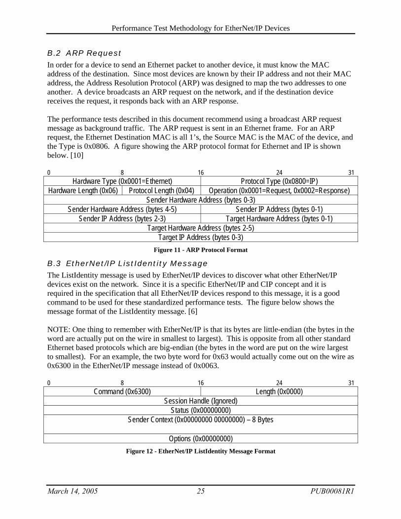
B.2 ARP Request In order for a device to send an Ethernet packet to another device, it must know the MAC address of the destination. Since most devices are known by their IP address and not their MAC address, the Address Resolution Protocol (ARP) was designed to map the two addresses to one another. A device broadcasts an ARP request on the network, and if the destination device receives the request, it responds back with an ARP response. The performance tests described in this document recommend using a broadcast ARP request message as background traffic. The ARP request is sent in an Ethernet frame. For an ARP request, the Ethernet Destination MAC is all 1’s, the Source MAC is the MAC of the device, and the Type is 0x0806. A figure showing the ARP protocol format for Ethernet and IP is shown below. [10] 0 8 16 24 31
Hardware Type (0x0001=Ethernet) Protocol Type (0x0800=IP) Hardware Length (0x06) Protocol Length (0x04) Operation (0x0001=Request, 0x0002=Response)
Sender Hardware Address (bytes 0-3) Sender Hardware Address (bytes 4-5) Sender IP Address (bytes 0-1)
Sender IP Address (bytes 2-3) Target Hardware Address (bytes 0-1) Target Hardware Address (bytes 2-5)
Target IP Address (bytes 0-3) Figure 11 - ARP Protocol Format
B.3 EtherNet/IP ListIdentity Message The ListIdentity message is used by EtherNet/IP devices to discover what other EtherNet/IP devices exist on the network. Since it is a specific EtherNet/IP and CIP concept and it is required in the specification that all EtherNet/IP devices respond to this message, it is a good command to be used for these standardized performance tests. The figure below shows the message format of the ListIdentity message. [6] NOTE: One thing to remember with EtherNet/IP is that its bytes are little-endian (the bytes in the word are actually put on the wire in smallest to largest). This is opposite from all other standard Ethernet based protocols which are big-endian (the bytes in the word are put on the wire largest to smallest). For an example, the two byte word for 0x63 would actually come out on the wire as 0x6300 in the EtherNet/IP message instead of 0x0063. 0 8 16 24 31
Command (0x6300) Length (0x0000) Session Handle (Ignored)
Status (0x00000000) Sender Context (0x00000000 00000000) – 8 Bytes
Options (0x00000000) Figure 12 - EtherNet/IP ListIdentity Message Format

Performance Test Methodology for EtherNet/IP Devices
March 14, 2005 26 PUB00081R1
Appendix C Calculating a Statistically Significant Number of Samples
It is important to know how many times a particular measurement needs to be performed in order to obtain a statistically significant number of samples. By using the principles of statistics, some general practice numbers of samples can be determined relatively easily. Since the individual samples are independent from each other and random, the values can be represented as a Gaussian random variable for a large number of samples. Gaussian random variables are well understood, but many of the values associated with them need to be computed numerically due to their complexity. One of these values is the Cumulative Distribution Function (CDF) which represents the probability that an individual sample lies outside a particular range. The Gaussian CDF has been tabulated in many statistics or communications textbooks. [11] The next part of the process is to determine the number of samples from the probability value determined from the Gaussian tables. The Average Run Length (ARL) will be an integer number of samples calculated from the mean of the Gaussian random variable above. ARL is greater than or equal to the inverse of the Gaussian CDF.
( )xQP ×−= 21
( )xQARL
×≥
21
Where P = Probability Sample within Range
Q(x) = Gaussian CDF ARL = Average Run Length (integer value)
# of Standard Dev. Q(x) P (%) ARL
1 1.587e-1 68.26% 4 2 2.275e-2 95.45% 22 3 1.350e-3 99.73% 371 4 3.167e-5 99.9937% 15788


