Performances of solar combisystems with advanced storage concepts A Report of IEA Solar Heating and Cooling programme - Task 32 Advanced storage concepts for solar and low energy buildings Report A3 of Subtask A December 2007 Edited by: Thomas Letz Contributions from: Elsa Andersen Chris Bales Jacques Bony Richard Heimrath, Michel Haller Robert Haberl Jean-Christophe Hadorn Dagmar Jaehnig Henner Kerskes Jorgen Schultz Robert Weber Herbert Zondag
Transcript
Performances of solar combisystems with advanced storage concepts A Report of IEA Solar Heating and Cooling programme - Task 32 Advanced storage concepts for solar and low energy buildings Report A3 of Subtask A December 2007
Edited by: Thomas Letz Contributions from: Elsa Andersen Chris Bales Jacques Bony Richard Heimrath, Michel Haller Robert Haberl Jean-Christophe Hadorn Dagmar Jaehnig Henner Kerskes Jorgen Schultz Robert Weber Herbert Zondag
2
Performances of solar combisystems
with advanced storage concepts
by Thomas Letz (editor)*
Contributions from:
Elsa Andersen, DTU, Copenhagen, Denmark
Chris Bales, SERC, Borlänge, Sweden
Jacques Bony, Heig-Vd, Yverdon, Switzerland
Richard Heimrath, Michel Haller, IWT, Graz, Austria
Robert Haberl, SPF, Rapperswil, Switzerland
Jean-Christophe Hadorn, BASE Consultants SA, Geneva, , Switzerland
Dagmar Jaehnig, AEE Intec, Gleisdorf, Austria
Henner Kerskes, ITW, Stuttgart, Germany
Jorgen Schultz, DTU, Copenhagen, Denmark
Robert Weber, EMPA, Zürich, Switzerland
Herbert Zondag, ECN, Petten, Netherlands
A technical report of Subtask A
* INES - Education Parc Technologique de Savoie Technolac
50 avenue du Léman BP 258 F - 73 375 LE BOURGET DU LAC Cedex
IEA SHC – Task 32 – Advanced storage concepts
3
Executive Summary In a previous IEA SHC work, Task 26 "Solar Combisystems", nine different systems were compared using a new characterization method developed in the framework of the task, and based on a parabolic relationship between the thermal or extended fractional energy savings and a new proposed parameter called Fractional Solar Consumption (FSC). FSC could be fruitfully used for systems with limited Fractional energy savings, but is not adapted for systems designed for high Fractional energy savings. Therefore an extended definition of FSC called FSC' has been proposed and tested. In the present report, simulation results for nine different systems are presented: five for systems using water storages, one for a system using a storage with Phase Change Material (PCM), and three for systems using chemical or sorption storages. Curves have been drawn for two indicators: the thermal end the extended Fractional energy savings. These characteristic curves allow seeing at one glance how a system performs. They are similar to the characteristic curves of solar collectors, which allow visualising the performances of different concepts. Several systems with advanced storage techniques have been simulated by Task 32 participants with the Task framework and the simulation models developed throughout the 4 years of the Task. The framework proved to work well. Each simulated system can be referenced with its characteristic curve Fsav vs FSC’ which is independent of the climate and the load ! This report presents the detailed analysis of all systems simulated with the Task 32 framework.
IEA SHC – Task 32 – Advanced storage concepts
4
IEA Solar Heating and Cooling Programme
The International Energy Agency (IEA) is an autonomous body within the framework of the Organization for Economic Co-operation and Development (OECD) based in Paris. Established in 1974 after the first “oil shock,” the IEA is committed to carrying out a comprehensive program of energy cooperation among its members and the Commission of the European Communities. The IEA provides a legal framework, through IEA Implementing Agreements such as the Solar Heating and Cooling Agreement, for international collaboration in energy technology research and development (R&D) and deployment. This IEA experience has proved that such collaboration contributes significantly to faster technological progress, while reducing costs; to eliminating technological risks and duplication of efforts; and to creating numerous other benefits, such as swifter expansion of the knowledge base and easier harmonization of standards. The Solar Heating and Cooling Programme was one of the first IEA Implementing Agreements to be established. Since 1977, its members have been collaborating to advance active solar and passive solar and their application in buildings and other areas, such as agriculture and industry. Current members are: Australia Finland Portugal Austria France Spain Belgium Italy Sweden Canada Mexico Switzerland Denmark Netherlands United States European Commission New Zealand Germany Norway A total of 39 Tasks have been initiated, 30 of which have been completed. Each Task is managed by an Operating Agent from one of the participating countries. Overall control of the program rests with an Executive Committee comprised of one representative from each contracting party to the Implementing Agreement. In addition to the Task work, a number of special activities—Memorandum of Understanding with solar thermal trade organizations, statistics collection and analysis, conferences and workshops—have been undertaken.
IEA SHC – Task 32 – Advanced storage concepts
5
The Tasks of the IEA Solar Heating and Cooling Programme, both underway and completed are as follows: Current Tasks: Task 32 Advanced Storage Concepts for Solar and Low Energy Buildings Task 33 Solar Heat for Industrial Processes Task 34 Testing and Validation of Building Energy Simulation Tools Task 35 PV/Thermal Solar Systems Task 36 Solar Resource Knowledge Management Task 37 Advanced Housing Renovation with Solar & Conservation Task 38 Solar Assisted Cooling Systems Task 39 Polymeric Materials for Solar Thermal Applications Completed Tasks: Task 1 Investigation of the Performance of Solar Heating and Cooling Systems Task 2 Coordination of Solar Heating and Cooling R&D Task 3 Performance Testing of Solar Collectors Task 4 Development of an Insolation Handbook and Instrument Package Task 5 Use of Existing Meteorological Information for Solar Energy Application Task 6 Performance of Solar Systems Using Evacuated Collectors Task 7 Central Solar Heating Plants with Seasonal Storage Task 8 Passive and Hybrid Solar Low Energy Buildings Task 9 Solar Radiation and Pyranometry Studies Task 10 Solar Materials R&D Task 11 Passive and Hybrid Solar Commercial Buildings Task 12 Building Energy Analysis and Design Tools for Solar Applications Task 13 Advance Solar Low Energy Buildings Task 14 Advance Active Solar Energy Systems Task 16 Photovoltaics in Buildings Task 17 Measuring and Modeling Spectral Radiation Task 18 Advanced Glazing and Associated Materials for Solar and Building Applications Task 19 Solar Air Systems Task 20 Solar Energy in Building Renovation Task 21 Daylight in Buildings Task 23 Optimization of Solar Energy Use in Large Buildings Task 22 Building Energy Analysis Tools Task 24 Solar Procurement Task 25 Solar Assisted Air Conditioning of Buildings Task 26 Solar Combisystems Task 28 Solar Sustainable Housing Task 27 Performance of Solar Facade Components Task 29 Solar Crop Drying Task 31 Daylighting Buildings in the 21st Century Completed Working Groups: CSHPSS, ISOLDE, Materials in Solar Thermal Collectors, and the Evaluation of Task 13 Houses To find Solar Heating and Cooling Programme publications and learn more about the Programme visit www.iea-shc.org or contact the SHC Executive Secretary, Pamela Murphy, e-mail: [email protected] September 2007
What is IEA SHC Task 32 “Advanced Storage Concepts for solar and low energy buildings” ?
The main goal of this Task is to investigate new or advanced solutions for storing heat in systems providing heating or cooling for low energy buildings.
o The first objective is to contribute to the development of advanced storage solutions in thermal solar systems for buildings that lead to high solar fraction up to 100% in a typical 45N latitude climate.
o The second objective is to propose advanced storage solutions for other heating or cooling technologies than solar, for example systems based on current compression and absorption heat pumps or new heat pumps based on the storage material itself.
Applications that are included in the scope of this task include:
o new buildings designed for low energy consumption
o buildings retrofitted for low energy consumption.
The ambition of the Task is not to develop new storage systems independent of a system application. The focus is on the integration of advanced storage concepts in a thermal system for low energy housing. This provides both a framework and a goal to develop new technologies.
IEA SHC Task 32 Subtask A “Evaluation and dissemination”
This report is part of Subtask A of the Task 32 of the Solar Heating and Cooling Programme of the International Energy Agency dealing with evaluation of new storage concepts. Different storage options for solar combisystems that should meet the same reference load of one family house in different climates have been analyzed by experts participating in Task 32. This report presents the results for each system individually. An attempt to compare systems is given in an other document. The Operating Agent would like to thank all contributors of this report and specially Thomas Letz who set up the methodology to derive the new FSC’ factor and was at the forefront of the production of this report. Jean-Christophe Hadorn Operating Agent of IEA SHC Task 32 for the Swiss Federal Office of Energy BASE Consultants SA - Geneva [email protected]
NOTICE:
The Solar Heating and Cooling Programme, also known as the Programme to Develop and Test Solar Heating and Cooling Systems, functions within a framework created by the International Energy Agency (IEA). Views, findings and publications of the Solar Heating and Cooling Programme do not necessarily represent the views or policies of the IEA Secretariat or of all its individual member countries.
IEA SHC – Task 32 – Advanced storage concepts
8
Contents 1 Evaluation based on the FSC’ indicator ................................................................................9 2 Note on solar collector types ...............................................................................................10 3 Solar combisystems with water storage ..............................................................................11
3.1 The Template solar system .........................................................................................11 3.2 DTU system, without stratifiers ....................................................................................14 3.3 DTU system, with stratifiers .........................................................................................16 3.4 HEIG-VD system .........................................................................................................18 3.5 SPF system .................................................................................................................21
4 Solar combisystems with phase change material (PCM) storage .......................................27
4.1 HEIG-VD system .........................................................................................................27 4.2 University of Lleida system..........................................................................................30 4.3 DTU system.................................................................................................................31
5 Solar combisystems with sorption storage ..........................................................................33
5.1 AEE Intec system (Modestore) ....................................................................................33 5.2 ECN system.................................................................................................................36 5.3 ITW system..................................................................................................................39 5.4 EMPA system ..............................................................................................................41 5.5 TCA system .................................................................................................................42
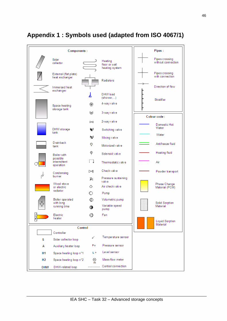
6 Conclusions.........................................................................................................................44 7 References ..........................................................................................................................45 8 Appendice : Symbols used (adapted from ISO 4067/1) ......................................................46
IEA SHC – Task 32 – Advanced storage concepts
9
Evaluation based on the FSC’ indicator Task 32 was aiming at developping and better understanding advanced storage concepts mainly for solar combisystems. Three types of solar combisystems (SCS) have been investigated:
- Storage concepts based on water storage (subtask D of Task 32) - Storage concepts based on PCM (Phase Change Material) storage (subtask C) - Storage concepts based on chemical reactions (sorption storages) (subtask B)
More detailed reports of some systems are available on the website: http://www.iea-shc.org/task32/publications/index.html Teams have developed along the Task duration their concept for a new storage. Throughout this document, systems are named according to the laboratory involved in their development. A basic indicator is a quantitative measure of the performance of a solar combisystem. An analysis in terms of system energy performance will be done using the newly developed FSC' method (Letz T., 2007), and on the basis of the reference conditions established within Subtask A at IWT Graz (Heimrath R. Haller M., 2007). Reference (Letz T., 2007, Report A1 of IEA SHC Task 32) presents the details of the FSC’ method. During the last year of Task 32, each new storage concept for which a simulation model had also been derived was “plugged” into a reference solar combisystem so that a certain level of quantitative comparison of several storage concepts could be achieved. This method has primarily been used to derive the “solar fraction” of a system, or its “Fractional energy savings” a more modern concept derived in IEA SHC. For each system simulated, diagrams giving the thermal fractional energy savings (Fsav,th) or the extended fractional energy savings (Fsav,ext) are shown. Only simulation results corresponding to system efficiency (the ratio between the annual thermal energy savings and the annual irradiation available on the collector area) higher than 15 % have been taken into consideration to draw the characteristic curves of the systems. A value smaller than 15 % reveals that the system is not well dimensioned, whatever it is due to an oversized collector compared to the load, or to an undersized storage capacity. This arbitrary choice allows avoiding irrelevant values.
Note on solar collector types Due to the temperature level required by each storage system, different types of solar collectors have to be used. For this reason the curves on the following diagrams cannot be strictly compared. Systems using water or PCM storages have been simulated with the reference selective flat plate collector defined in Task 32 framework [Heimrath R., Haller M. (2007)] Systems using sorption storages, except the ITW system, have been simulated with the reference vacuum tubes collector of the common framework [Heimrath R., Haller M. (2007)] The ITW system has been simulated with a CPC vacuum tube collector (Microtherm). These three types of collectors are defined in Table 1 and compared in Figure 1.
Fig 1: Efficiency curves of the 3 reference solar collectors (E = 800 W/m²)
IEA SHC – Task 32 – Advanced storage concepts
11
Solar combisystems with water storage Four different systems have been simulated:
1. The “Template” Solar system 2. DTU system, without and with stratifiers 3. Heig-Vd system 4. SPF system
1.1 The Template solar system Developed by: Richard Heimrath, Michel Haller at Graz University, Austria Detailed features of the system are given in: www.iea-shc.org/task32/publications/IEA_SHC_Task_32_Report_A2_May_2007.pdfSimulations made by: Thomas Letz at INES France Solar collector: reference selective flat plate Main features This is the basic system. It can be simply described as a 2005 state-of-the-art solar combisystem in Europe with a water tank storage already quite efficient. Every “new or advanced” system should in the end be compared to this “Template” solar system.
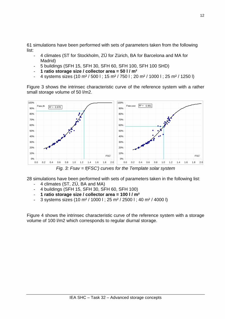
61 simulations have been performed with sets of parameters taken from the following list:
- 4 climates (ST for Stockholm, ZÜ for Zürich, BA for Barcelona and MA for Madrid)
- 5 buildings (SFH 15, SFH 30, SFH 60, SFH 100, SFH 100 SHD) - 1 ratio storage size / collector area = 50 l / m² - 4 systems sizes (10 m² / 500 l ; 15 m² / 750 l ; 20 m² / 1000 l ; 25 m² / 1250 l)
Figure 3 shows the intrinsec characteristic curve of the reference system with a rather small storage volume of 50 l/m2.
0%
10%
20%
30%
40%
50%
60%
70%
80%
90%
100%
0.0 0.2 0.4 0.6 0.8 1.0 1.2 1.4 1.6 1.8 2.0
FSC'
Fsav,th R² = 0.978
0%
10%
20%
30%
40%
50%
60%
70%
80%
90%
100%
0.0 0.2 0.4 0.6 0.8 1.0 1.2 1.4 1.6 1.8 2.0
FSC'
Fsav,ext R² = 0.951
Fig. 3: Fsav = f(FSC') curves for the Template solar system
28 simulations have been performed with sets of parameters taken in the following list:
- 4 climates (ST, ZÜ, BA and MA) - 4 buildings (SFH 15, SFH 30, SFH 60, SFH 100) - 1 ratio storage size / collector area = 100 l / m² - 3 systems sizes (10 m² / 1000 l ; 25 m² / 2500 l ; 40 m² / 4000 l)
Figure 4 shows the intrinsec characteristic curve of the reference system with a storage volume of 100 l/m2 which corresponds to regular diurnal storage.
IEA SHC – Task 32 – Advanced storage concepts
13
0%
10%
20%
30%
40%
50%
60%
70%
80%
90%
100%
0.0 0.2 0.4 0.6 0.8 1.0 1.2 1.4 1.6 1.8 2.0
FSC'
Fsav,th R² = 0.980
0%
10%
20%
30%
40%
50%
60%
70%
80%
90%
100%
0.0 0.2 0.4 0.6 0.8 1.0 1.2 1.4 1.6 1.8 2.0
FSC'
Fsav,ext R² = 0.972
Fig. 4: Fsav = f(FSC') curves for the Template solar system
IEA SHC – Task 32 – Advanced storage concepts
14
1.2 DTU system, without stratifiers Developed by: DTU Lyngby, Denmark Solar collector: reference selective flat plate Main features The solar combisystem is meant to supply a single family house with domestic hot water and space heating (Figure 5). The solar combisystem is based on a central storage for space heating but with an external heat exchanger mounted in a side arm for domestic hot water preparation. Solar energy is transferred to the storage through an immersed heat exchanger spiral situated in the lower part of the storage (relative inlet/outlet height 0.3/0.01) and direct flow outlet to and return inlet from the space heating loop (relative return inlet height 0.3). The rest of the system is similar to the Template solar system.
Fig. 5: Diagram of the DTU system without stratifiers
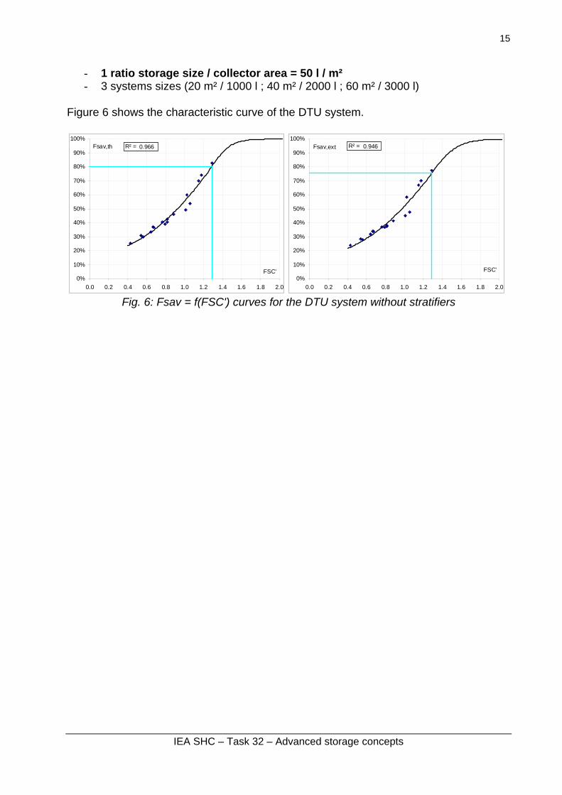
17 simulations have been performed with sets of parameters taken from the following list:
- 4 climates (ST, ZÜ, BA and MA) - 4 buildings (SFH 15, SFH 30, SFH 60, SFH 100)
IEA SHC – Task 32 – Advanced storage concepts
15
- 1 ratio storage size / collector area = 50 l / m² - 3 systems sizes (20 m² / 1000 l ; 40 m² / 2000 l ; 60 m² / 3000 l)
Figure 6 shows the characteristic curve of the DTU system.
0%
10%
20%
30%
40%
50%
60%
70%
80%
90%
100%
0.0 0.2 0.4 0.6 0.8 1.0 1.2 1.4 1.6 1.8 2.0
FSC'
Fsav,th R² = 0.966
0%
10%
20%
30%
40%
50%
60%
70%
80%
90%
100%
0.0 0.2 0.4 0.6 0.8 1.0 1.2 1.4 1.6 1.8 2.0
FSC'
Fsav,ext R² = 0.946
Fig. 6: Fsav = f(FSC') curves for the DTU system without stratifiers
IEA SHC – Task 32 – Advanced storage concepts
16
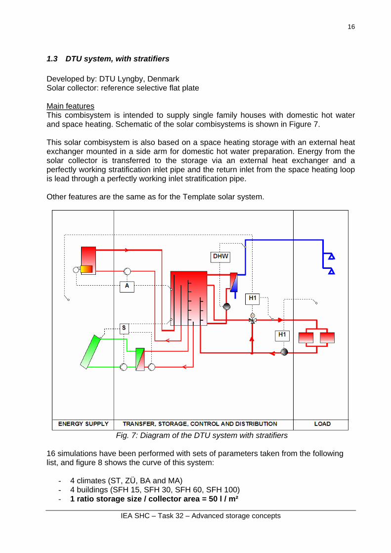
1.3 DTU system, with stratifiers Developed by: DTU Lyngby, Denmark Solar collector: reference selective flat plate Main features This combisystem is intended to supply single family houses with domestic hot water and space heating. Schematic of the solar combisystems is shown in Figure 7. This solar combisystem is also based on a space heating storage with an external heat exchanger mounted in a side arm for domestic hot water preparation. Energy from the solar collector is transferred to the storage via an external heat exchanger and a perfectly working stratification inlet pipe and the return inlet from the space heating loop is lead through a perfectly working inlet stratification pipe. Other features are the same as for the Template solar system.
Fig. 7: Diagram of the DTU system with stratifiers
16 simulations have been performed with sets of parameters taken from the following list, and figure 8 shows the curve of this system:
- 4 climates (ST, ZÜ, BA and MA) - 4 buildings (SFH 15, SFH 30, SFH 60, SFH 100) - 1 ratio storage size / collector area = 50 l / m²
IEA SHC – Task 32 – Advanced storage concepts
17
- 3 systems sizes (20 m² / 1000 l ; 40 m² / 2000 l ; 60 m² / 3000 l)
0%
10%
20%
30%
40%
50%
60%
70%
80%
90%
100%
0.0 0.2 0.4 0.6 0.8 1.0 1.2 1.4 1.6 1.8 2.0
FSC'
Fsav,th R² = 0.961
0%
10%
20%
30%
40%
50%
60%
70%
80%
90%
100%
0.0 0.2 0.4 0.6 0.8 1.0 1.2 1.4 1.6 1.8 2.0
FSC'
Fsav,ext R² = 0.920
Fig. 8: Fsav = f(FSC') curves for the DTU system with stratifiers
IEA SHC – Task 32 – Advanced storage concepts
18
1.4 HEIG-VD system Developed by: HEIG-VD, Yverdon, Switzerland Solar collector: reference selective flat plate Main features This system was design for a single family house to provide energy for the space heating and the domestic hot water (DHW). The solar collector loop of this installation is a drain back system. The storage tank, space heating and solar loop use water as heat transfer fluid. DHW preparation is done with an external flat plate heat exchanger. The space heating demand is met by solar energy and a gas boiler as back-up. Heat management philosophy Solar loop: When the collector temperature is higher than the bottom temperature of the storage tank, the solar pump is switched on. The solar loop uses a constant flow rate without stratification. Auxiliary boiler: The gas boiler has a modulated burner. It provides energy for the space heating loop without going through the storage tank. There is no heat charge in the space heating part of the tank. Thus the storage heat losses are reduced and the part of the tank devoted to solar can be bigger than usual. Space heating: If the return temperature of the space heating loop is lower than the temperature in the middle of the tank, the energy is taken from the storage tank. If the temperature level in the tank is not high enough, the gas boiler switches on. The set point temperature for the space heating loop depends of the outside temperature and the room temperature. Preparation of DHW: The auxiliary heat for the DHW demand is provided by the gas burner, and during this step, the space heating loop is interrupted. In the upper part (DHW) of the tank, the set point temperature is 57 °C with a dead band of ±3 °K. The DHW temperature at the output of the external heat exchanger is regulated by a temperature control valve. Due to the instantaneous DHW preparation, there is no legionella risk. Influence of auxiliary energy source on system design and dimensioning As there is no buffer storage the space heating loop requires a modulated burner. If a non modulated burner is used, there is a risk of start-up cycling. On the other hand, the space heating demand influences only the nominal power of the boiler.
IEA SHC – Task 32 – Advanced storage concepts
19
Fig. 9: Diagram of the HEIG-VD system
62 simulations have been performed with sets of parameters taken from the following list and results are shown in figure 10:
- 4 climates (ST, ZÜ, BA and MA) - 5 buildings (SFH 15, SFH 30, SFH 60, SFH 100, SFH 100 SHD) - 1 storage = 830 l - 4 systems sizes (10 m², 15 m², 20 m², 25 m²)
0%
10%
20%
30%
40%
50%
60%
70%
80%
90%
100%
0.0 0.2 0.4 0.6 0.8 1.0 1.2 1.4 1.6 1.8 2.0
FSC'
Fsav,th R² = 0.941
0%
10%
20%
30%
40%
50%
60%
70%
80%
90%
100%
0.0 0.2 0.4 0.6 0.8 1.0 1.2 1.4 1.6 1.8 2.0
FSC'
Fsav,ext R² = 0.939
Fig. 10: Fsav = f(FSC') curves for the HEIG-VD system
IEA SHC – Task 32 – Advanced storage concepts
20
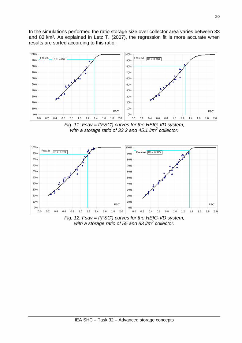
In the simulations performed the ratio storage size over collector area varies between 33 and 83 l/m². As explained in Letz T. (2007), the regression fit is more accurate when results are sorted according to this ratio:
0%
10%
20%
30%
40%
50%
60%
70%
80%
90%
100%
0.0 0.2 0.4 0.6 0.8 1.0 1.2 1.4 1.6 1.8 2.0
FSC'
Fsav,th R² = 0.963
0%
10%
20%
30%
40%
50%
60%
70%
80%
90%
100%
0.0 0.2 0.4 0.6 0.8 1.0 1.2 1.4 1.6 1.8 2.0
FSC'
Fsav,ext R² = 0.960
Fig. 11: Fsav = f(FSC') curves for the HEIG-VD system,
with a storage ratio of 33.2 and 45.1 l/m2 collector.
0%
10%
20%
30%
40%
50%
60%
70%
80%
90%
100%
0.0 0.2 0.4 0.6 0.8 1.0 1.2 1.4 1.6 1.8 2.0
FSC'
Fsav,th R² = 0.970
0%
10%
20%
30%
40%
50%
60%
70%
80%
90%
100%
0.0 0.2 0.4 0.6 0.8 1.0 1.2 1.4 1.6 1.8 2.0
FSC'
Fsav,ext R² = 0.975
Fig. 12: Fsav = f(FSC') curves for the HEIG-VD system,
with a storage ratio of 55 and 83 l/m2 collector.
IEA SHC – Task 32 – Advanced storage concepts
21
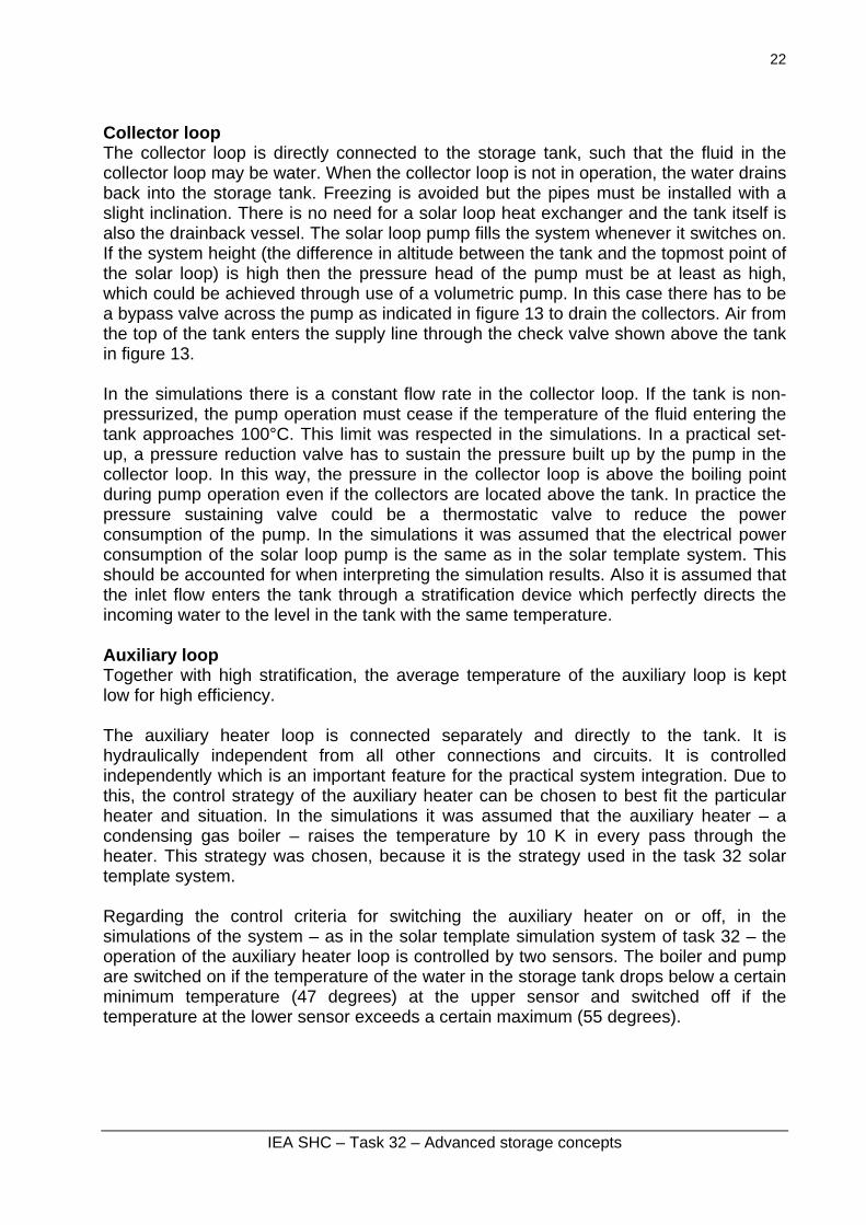
1.5 SPF system Developed by: SPF Rapperswil, Switzerland Solar collector: reference selective flat plate Main features This system is a hypothetical system. The simulated system could be built with components readily available on the market (with the exception of some specific controller functions, which would be easy to implement). Modularity and material use The core of the system is a simple water tank which can be non-pressurized. If the tank is non-pressurized it may be vented or closed. If it is closed, there will have to be provision to allow for the temperature induced expansion of the water (plus air or gas for the drainback function). Even though a non-pressurized tank seems to be the logical solution, there is no technical problem in using a pressurized tank instead. A reasonable compromise might be a store which is closed and may be moderately pressurized. Another possibility to be considered is a closed non-pressurized store and expansion implemented with a hydraulically communicating simple flexible vessel such as an impermeable bag. The “flexible vessel” could be connected to the top of the tank and contain air or gas only. Or it could be connected to the bottom of the tank (but located above the water level). It could also be located clearly above the tank to solicit the tank to a moderate but sharply defined pressure. The concept is based on a simple store design and separate components at its periphery which are connected to the store by independent hydraulic circuits, as e.g. the auxiliary heater. There are no heat exchangers built into the store (with the exception, perhaps, of the domestic hot water heating, which could be achieved with any of the methods common with solar combistores). Auxiliary heating and technical integration The types of auxiliary heaters the system should be well suited to be combined with are:
- Heat pumps with their difficulties to achieve the temperatures necessary for hot water production
- Condensing boilers - Wood boilers which require a sufficient storage capacity: Some storage capacity
is also beneficial for pellets and other heavy boilers. - Any existing auxiliary heater: In many cases, an existing heating device stays in
place when solar heating is installed. The system concept should allow for easy integration of virtually any existing boiler with the solar energy system. The hydraulic connection should be simple and clear. The control of the auxiliary heater and the (new) control strategy of the auxiliary heater and its (old) controller should be equally simple.
Heat management philosophy
IEA SHC – Task 32 – Advanced storage concepts
22
Collector loop The collector loop is directly connected to the storage tank, such that the fluid in the collector loop may be water. When the collector loop is not in operation, the water drains back into the storage tank. Freezing is avoided but the pipes must be installed with a slight inclination. There is no need for a solar loop heat exchanger and the tank itself is also the drainback vessel. The solar loop pump fills the system whenever it switches on. If the system height (the difference in altitude between the tank and the topmost point of the solar loop) is high then the pressure head of the pump must be at least as high, which could be achieved through use of a volumetric pump. In this case there has to be a bypass valve across the pump as indicated in figure 13 to drain the collectors. Air from the top of the tank enters the supply line through the check valve shown above the tank in figure 13. In the simulations there is a constant flow rate in the collector loop. If the tank is non-pressurized, the pump operation must cease if the temperature of the fluid entering the tank approaches 100°C. This limit was respected in the simulations. In a practical set-up, a pressure reduction valve has to sustain the pressure built up by the pump in the collector loop. In this way, the pressure in the collector loop is above the boiling point during pump operation even if the collectors are located above the tank. In practice the pressure sustaining valve could be a thermostatic valve to reduce the power consumption of the pump. In the simulations it was assumed that the electrical power consumption of the solar loop pump is the same as in the solar template system. This should be accounted for when interpreting the simulation results. Also it is assumed that the inlet flow enters the tank through a stratification device which perfectly directs the incoming water to the level in the tank with the same temperature. Auxiliary loop Together with high stratification, the average temperature of the auxiliary loop is kept low for high efficiency. The auxiliary heater loop is connected separately and directly to the tank. It is hydraulically independent from all other connections and circuits. It is controlled independently which is an important feature for the practical system integration. Due to this, the control strategy of the auxiliary heater can be chosen to best fit the particular heater and situation. In the simulations it was assumed that the auxiliary heater – a condensing gas boiler – raises the temperature by 10 K in every pass through the heater. This strategy was chosen, because it is the strategy used in the task 32 solar template system. Regarding the control criteria for switching the auxiliary heater on or off, in the simulations of the system – as in the solar template simulation system of task 32 – the operation of the auxiliary heater loop is controlled by two sensors. The boiler and pump are switched on if the temperature of the water in the storage tank drops below a certain minimum temperature (47 degrees) at the upper sensor and switched off if the temperature at the lower sensor exceeds a certain maximum (55 degrees).
IEA SHC – Task 32 – Advanced storage concepts
23
Space heating loop In the simulations the return flow of the space heating loop is directed to the tank via a stratification device (or “stratifier”). As in the case of the flow from the solar collectors, the computer model assumes perfect stratification within the specified extension of the stratifier (between the height of the inlet and outlet ports). The water is taken directly from the tank at a specific height to be supplied to the heat distribution system (in practice to radiators or to a radiant floor). There is a mixing valve to limit the flow temperature to 50°C. This temperature was chosen because this is often the maximum temperature permitted in the case of floor heating. In the simulations the temperature available at the respective position in the tank virtually always exceeds 50°C. The supply temperature after the mixing valve is 50°C whenever space heating is required. Earlier simulations had revealed that the mixing valve’s diminishing effect on the system efficiency is negligible. The energy supply to the radiators is regulated by modulating the flow rate in the heat distribution system. In a practical application, the flow would be adjusted according to the ambient temperature and possibly – in addition to it – the temperature in the house. In the simulations the flow rate varied to meet a given heat demand which was known from a load file. This control strategy, called DFFC (Direct Feed Flow Controlled), is very different from the current practice. The normal practice is to vary the supply temperature rather than to adjust the flow rate of energy transferred for space heating. The DFFC control strategy significantly enhances system performance, because the high flow temperature leads to a low flow rate and a low return temperature. Consequently there is better stratification in the tank which improves the efficiency of both the auxiliary gas heater and the solar collectors. Earlier simulation work suggested that the DFFC concept reduces gas consumption by 2.5%. One half of this reduction is due to the higher solar gains, the other half is due to the higher boiler efficiency. Hot water preparation In the simulations of the system the hot water was prepared with the same concept as in the simulations of the Task 32 solar template system: instantaneous water heating by means of a heat exchanger. The same components (including the controller) were used. However, the heat transfer rate of the heat exchanger was slightly reduced. The concept of instantaneous water heating via a heat exchanger with a high heat transfer rate leads to high stratification and consequently high solar gains, which are not representative.
IEA SHC – Task 32 – Advanced storage concepts
24
Fig. 13: Diagram of the SPF system
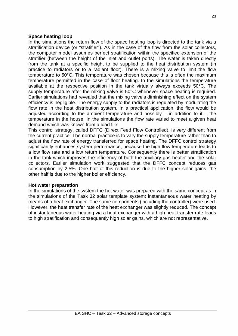
2 series of simulations have been performed: • 102 simulations with sets of parameters taken in the following list:
- 4 climates (ST, ZÜ, BA and MA) - 4 buildings (SFH 15, SFH 30, SFH 60, SFH 100) - 1 ratio storage size / collector area = 70 l / m² - 4 systems sizes (8 m² / 560 l ; 10 m² / 700 l ; 12 m² / 840 l ; 14 m² / 980 l ; 16 m² /
1120 l ; 18 m ² / 1260 l ; 20 m² / 1400 l )
IEA SHC – Task 32 – Advanced storage concepts
25
0%
10%
20%
30%
40%
50%
60%
70%
80%
90%
100%
0.0 0.2 0.4 0.6 0.8 1.0 1.2 1.4 1.6 1.8 2.0
FSC'
Fsav,th R² = 0.981
0%
10%
20%
30%
40%
50%
60%
70%
80%
90%
100%
0.0 0.2 0.4 0.6 0.8 1.0 1.2 1.4 1.6 1.8 2.0
FSC'
Fsav,ext R² = 0.969
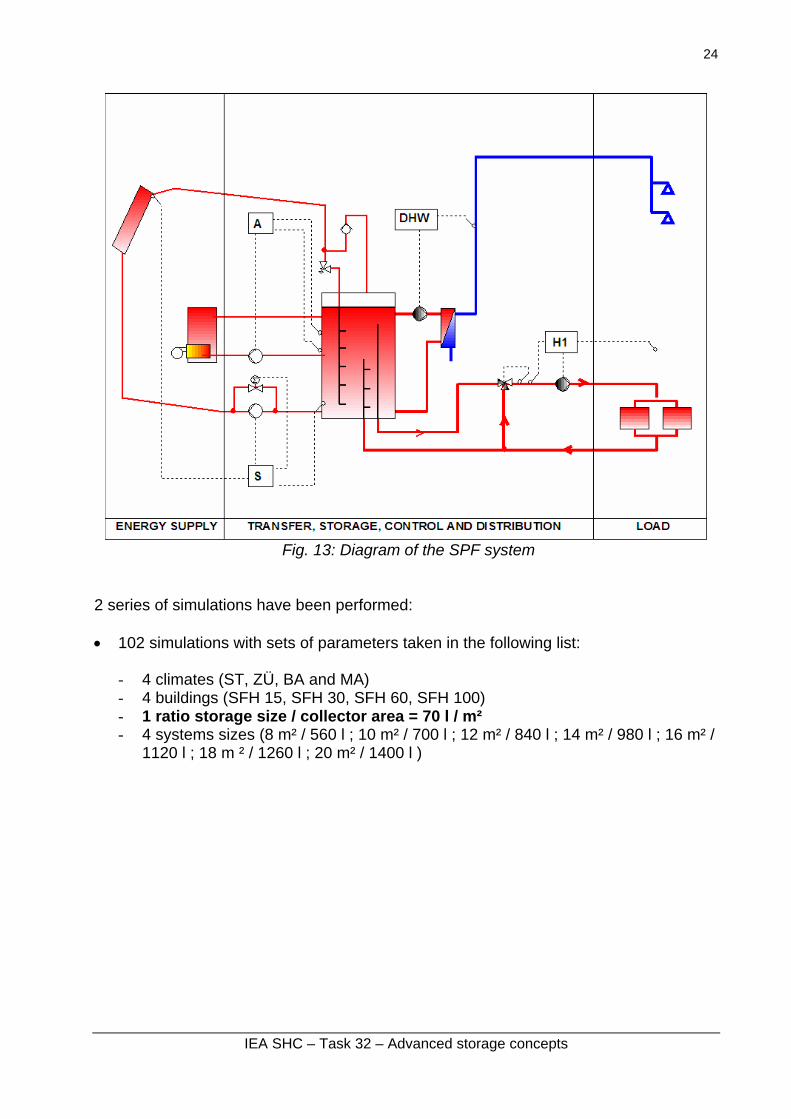
Fig. 14: Fsav = f(FSC') curves for the SPF system,
with a constant storage ratio (70 l/m2 collector).
• 112 simulations with sets of parameters taken from the following list:
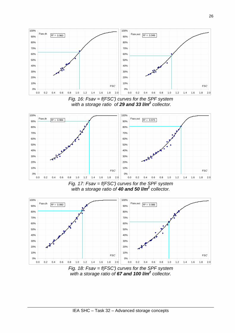
with a constant storage size (800 l). In these simulations the ratio storage size over collector area varies between 25 and 100 l/m². As explained in Letz T. (2007), the regression fit is better when results are sorted according to this ratio:
IEA SHC – Task 32 – Advanced storage concepts
26
0%
10%
20%
30%
40%
50%
60%
70%
80%
90%
100%
0.0 0.2 0.4 0.6 0.8 1.0 1.2 1.4 1.6 1.8 2.0
FSC'
Fsav,th R² = 0.960
0%
10%
20%
30%
40%
50%
60%
70%
80%
90%
100%
0.0 0.2 0.4 0.6 0.8 1.0 1.2 1.4 1.6 1.8 2.0
FSC'
Fsav,ext R² = 0.946
Fig. 16: Fsav = f(FSC') curves for the SPF system with a storage ratio of 29 and 33 l/m2 collector.
0%
10%
20%
30%
40%
50%
60%
70%
80%
90%
100%
0.0 0.2 0.4 0.6 0.8 1.0 1.2 1.4 1.6 1.8 2.0
FSC'
Fsav,th R² = 0.984
0%
10%
20%
30%
40%
50%
60%
70%
80%
90%
100%
0.0 0.2 0.4 0.6 0.8 1.0 1.2 1.4 1.6 1.8 2.0
FSC'
Fsav,ext R² = 0.975
Fig. 17: Fsav = f(FSC') curves for the SPF system
with a storage ratio of 40 and 50 l/m2 collector.
0%
10%
20%
30%
40%
50%
60%
70%
80%
90%
100%
0.0 0.2 0.4 0.6 0.8 1.0 1.2 1.4 1.6 1.8 2.0
FSC'
Fsav,th R² = 0.990
0%
10%
20%
30%
40%
50%
60%
70%
80%
90%
100%
0.0 0.2 0.4 0.6 0.8 1.0 1.2 1.4 1.6 1.8 2.0
FSC'
Fsav,ext R² = 0.986
Fig. 18: Fsav = f(FSC') curves for the SPF system with a storage ratio of 67 and 100 l/m2 collector.
IEA SHC – Task 32 – Advanced storage concepts
27
Solar combisystems with phase change material (PCM) storage Three systems have been considered:
- HEIG-VD system - University of Lleida system - DTU system.
The first one only could be simulated with Task 32 framework.
1.6 HEIG-VD system Developed by: HEIG-VD, Yverdon, Switzerland Solar collector: reference selective flat plate Main features This system is extrapolated from the one presented in paragraph 2.4. Modifications are described below. The water storage tank contains phase change material (PCM – yellow part of figure 19), but not in the upper part of the tank to get enough power to provide the DHW. The global ratio of PCM is about 50% in volume. Heat management philosophy Solar loop: When the collector temperature is higher than the bottom temperature of the storage tank, the solar pump is switched on. The solar loop uses a constant flow rate without stratification. The maximal temperature inside the storage tank depends on the PCM type. Some PCM does not support high temperature, therefore, if the storage tank temperature is too high (80°C for some PCM) or if the collector temperature is higher than 90°C the solar pump is switch off. Auxiliary boiler, space heating, preparation of DHW, Identical to the description in paragraph 2.4. Influence of auxiliary energy source on system design and dimensioning Identical to the description in paragraph 2.4.
IEA SHC – Task 32 – Advanced storage concepts
28
Fig. 19: Diagram of the HEIG-VD system with PCM
62 simulations have been performed with sets of parameters taken in the following list:
- 4 climates (ST, ZÜ, BA and MA) - 5 buildings (SFH 15, SFH 30, SFH 60, SFH 100, SFH 100 SHD) - 1 storage = 830 l - 4 systems sizes (10 m², 15 m², 20 m², 25 m²)
0%
10%
20%
30%
40%
50%
60%
70%
80%
90%
100%
0.0 0.2 0.4 0.6 0.8 1.0 1.2 1.4 1.6 1.8 2.0
FSC'
Fsav,th R² = 0.929
0%
10%
20%
30%
40%
50%
60%
70%
80%
90%
100%
0.0 0.2 0.4 0.6 0.8 1.0 1.2 1.4 1.6 1.8 2.0
FSC'
Fsav,ext R² = 0.934
Fig. 20: Fsav = f(FSC') curves for the HEIG-VD system with PCM
IEA SHC – Task 32 – Advanced storage concepts
29
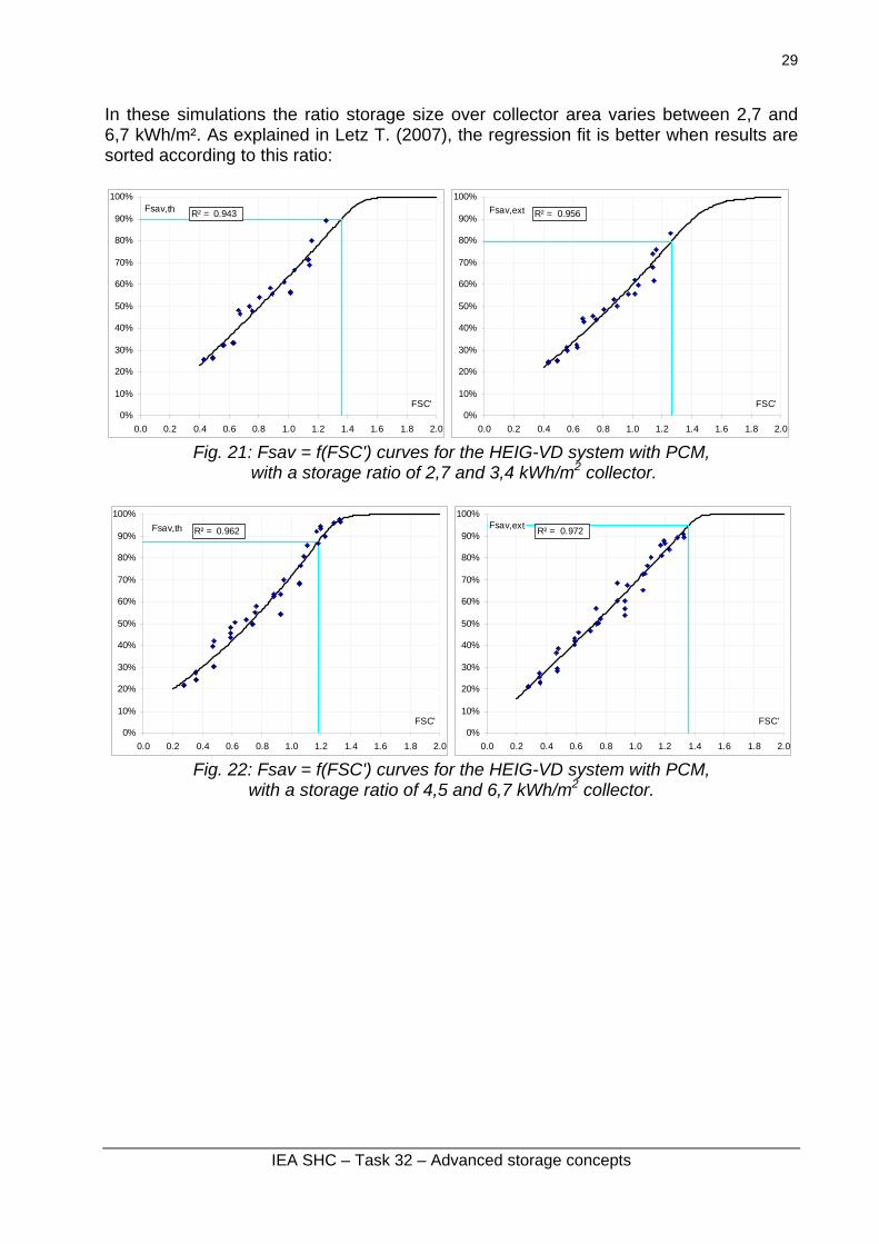
In these simulations the ratio storage size over collector area varies between 2,7 and 6,7 kWh/m². As explained in Letz T. (2007), the regression fit is better when results are sorted according to this ratio:
0%
10%
20%
30%
40%
50%
60%
70%
80%
90%
100%
0.0 0.2 0.4 0.6 0.8 1.0 1.2 1.4 1.6 1.8 2.0
FSC'
Fsav,th R² = 0.943
0%
10%
20%
30%
40%
50%
60%
70%
80%
90%
100%
0.0 0.2 0.4 0.6 0.8 1.0 1.2 1.4 1.6 1.8 2.0
FSC'
Fsav,ext R² = 0.956
Fig. 21: Fsav = f(FSC') curves for the HEIG-VD system with PCM,
with a storage ratio of 2,7 and 3,4 kWh/m2 collector.
0%
10%
20%
30%
40%
50%
60%
70%
80%
90%
100%
0.0 0.2 0.4 0.6 0.8 1.0 1.2 1.4 1.6 1.8 2.0
FSC'
Fsav,th R² = 0.962
0%
10%
20%
30%
40%
50%
60%
70%
80%
90%
100%
0.0 0.2 0.4 0.6 0.8 1.0 1.2 1.4 1.6 1.8 2.0
FSC'
Fsav,ext R² = 0.972
Fig. 22: Fsav = f(FSC') curves for the HEIG-VD system with PCM,
with a storage ratio of 4,5 and 6,7 kWh/m2 collector.
IEA SHC – Task 32 – Advanced storage concepts
30
1.7 University of Lleida system Developed by: Univ. of Lleida, Spain System is identical to the Template solar system, except that the storage tank contains phase change material in the upper part (PCM – yellow part in figure 23).
Fig. 23: Diagram of the University of Lleida system
Unfortunately no relevant simulations could be performed during the Task 32 period.
IEA SHC – Task 32 – Advanced storage concepts
31
1.8 DTU system Developed by: DTU, Lyngby, Denmark Main features The system is designed for 100% coverage by solar of both domestic hot water (DHW) and space heating in a low energy single family house according to the passive house standard. This is achieved by means of a seasonal phase change material (PCM) storage combined with a small DHW tank. The phase change material is sodium acetate tri-hydrate with a melting point of 58°C and the ability of stable supercooling. The PCM storage is subdivided into several sub-volumes. The system benefits from the supercooling as the PCM when melted can cool down, e.g. due to heat loss, to surrounding temperature in its liquid phase preserving the energy related to the heat of fusion. When a storage sub-volume has reached the surrounding temperature this part of the storage is heat loss free. As soon as there is a need for heating that cannot be covered directly from the collector or from a liquid or solidified sub-volume the solidification in a supercooled sub-volume is activated in which case the heat of fusion energy is released and becomes usable for DHW and/or space heating. The DHW tank is required to meet the power demand during hot water draw offs. The heating system is a low temperature system, i.e. floor heating or radiators. Heat management philosophy Solar collector loop: The pump in the solar collector loop is started if the temperature at the collector outlet is higher than either the minimum temperature of all sub-volumes in the PCM-storage or the minimum temperature in the DHW-tank or in case of space heating demand the return temperature from the space heating loop. When the pump in the solar collector loop is running the highest priority is on covering the space heating demand. Second priority is to heat up the DHW-tank until the set-point of 55°C has been reached. Third priority is to charge the seasonal PCM-storage. The strategy for charging of the PCM storage sub-volumes is to charge one sub-volume at the time until fully melted. In case the outlet temperature of the solar collector is lower than the melting point one sub-volume at the time is heated to the maximum obtainable temperature under the actual conditions. When all sub-volumes has been melted the DHW-tank is further heated until 70°C, where after the PCM-storage is charged. The pump stops either when the collector outlet temperature is lower than the minimum of the PCM storage sub-volume temperature, the minimum DHW-tank temperature and the space heating return temperature or when the DHW-tank has reached a temperature of 70°C and all sub-volumes in the PCM-storage has reached a temperature of 95°C. Demand loop: If possible the DHW-tank and/or the space heating loop are heated directly by the solar collector loop through the heat exchanger connecting the solar collector loop and the demand loop. In case the demand cannot be fulfilled by the collector loop the PCM-storage is discharged. The discharge strategy is first to discharge a liquid sub-volume that has a temperature just high enough to cover the demand temperature. Next a solidified sub-section with a sufficient temperature is discharged. Finally, the
IEA SHC – Task 32 – Advanced storage concepts
32
solidification is activated in a supercooled sub-section and discharged. The DHW-tank is always heated to the set-point temperature of 55°C. Auxiliary energy: The solar heating system is designed for 100% coverage by solar of DHW and space heating so in principle auxiliary energy is not needed. However, if required auxiliary energy is supplied by electric heating elements in the DHW-tank and in the space heating loop. Influence of auxiliary energy source on system design and dimensioning Auxiliary energy will only be needed in rare cases, i.e. in case of extremely bad summers or extremely hard winters or in case of malfunctioning of the system.
Fig. 24: Diagram of the DTU system
Unfortunately no relevant simulations could be performed during the Task 32 period.
IEA SHC – Task 32 – Advanced storage concepts
33
Solar combisystems with sorption storage Five different systems have been considered:
- AEE Intec system - ECN system - ITW system - EMPA system - TAC system.
The first three have been simulated with Task 32 framework.
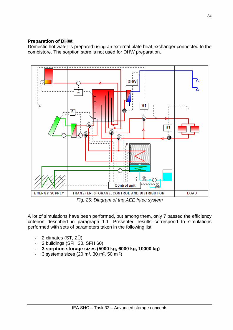
1.9 AEE Intec system (Modestore) Developed by: AEE Intec, Gleisdorf, Austria Solar collector: reference vacuum tube Main features The system is meant to supply low energy single-family houses with heat for domestic hot water and space heating. The system consists of a standard solar combisystem with an added sorption storage tank. This tank is charged during the summer months and discharged to provide heat for space heating in winter. As a heat sink for condensation in summer and as a heat source for evaporation in winter, a ground heat exchanger is used. Heat management philosophy Solar loop: The solar loop is used to charge primarily the water combistore. In summer when the combistore has reached a certain temperature, the excess heat from the collectors is used to charge the sorption store. In winter, the solar heat is used for domestic hot water preparation and space heating (as long as the temperature from the collectors is sufficient). Auxiliary boiler: The auxiliary boiler is used to heat the top part of the combistore to the set temperature for domestic hot water if the solar loop doesn’t provide enough energy. Below that, there is a section in the store that is reserved for space heating purposes. It is only charged by the auxiliary boiler if solar has not heated it to the necessary temperature for space heating AND if there is not enough energy in the sorption store. Space heating: Space heating is supplied from the combistore as long as the temperature in the store is high enough. If the temperature in the space heating section of the combistore drops below the set temperature, heat for space heating is taken from the sorption store by evaporating water until the set temperature is reached in the adsorber. Only when the sorption store is completely discharged, the space heating section of the combistore is charged with auxiliary heat and the space heating loop is supplied from there.
IEA SHC – Task 32 – Advanced storage concepts
34
Preparation of DHW: Domestic hot water is prepared using an external plate heat exchanger connected to the combistore. The sorption store is not used for DHW preparation.
Fig. 25: Diagram of the AEE Intec system
A lot of simulations have been performed, but among them, only 7 passed the efficiency criterion described in paragraph 1.1. Presented results correspond to simulations performed with sets of parameters taken in the following list:
Fig. 26: Fsav = f(FSC') curves for the AEE Intec system,
with a storage ratio of 10 and 47 kWh/m2 collector.
IEA SHC – Task 32 – Advanced storage concepts
36
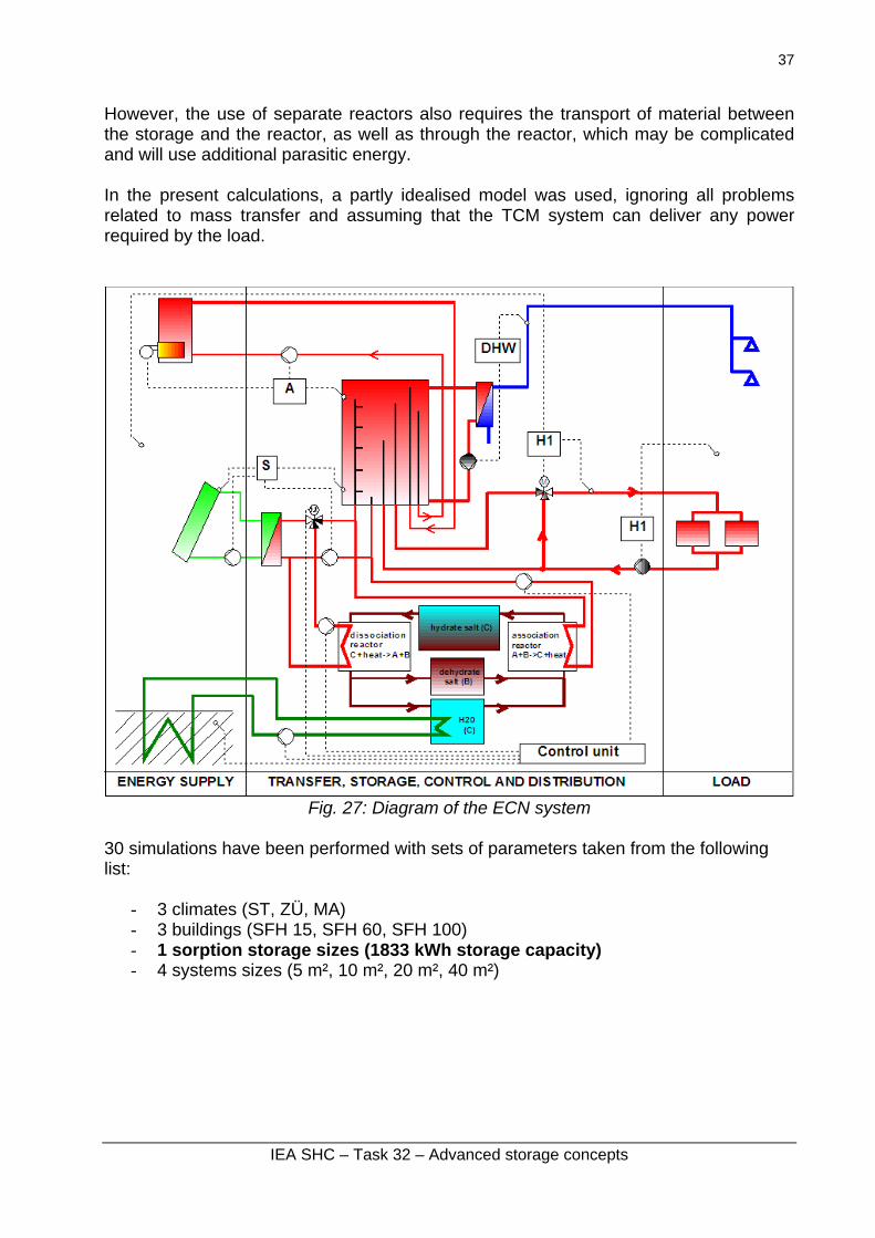
1.10 ECN system Developed by: ECN, Petten, The Netherlands Solar collector: reference vacuum tube Main features The system is meant for seasonal storage of solar heat for residential applications. The heat is stored by means of the hydration and dehydration of a salt. The selection of the salt is still ongoing. The charging of the store involves the endothermic dehydration of the salt in the dissociation reactor to a dehydrated salt and to water vapour which is condensed, the condensation energy being rejected to a borehole. There is a net flow of material from the storage vessel for the hydrated salt to the separate vessels for the dehydrated salt and the condensed water (see Figure 27). The discharge of the store, used for space heating and DHW, utilises the exothermic hydration in the association reactor of the salt by water vapour that has been evaporated using heat from the borehole. The TCM storage system thus works as a chemical heat pump, but with a very large internal storage capacity of several GJ. In the discharge phase there is a net flow of material from the separate storage vessels for the water and the dehydrated salt to the store for the hydrated salt. The process thus requires “pumping” of powder between the vessels and the reactors. Heat management philosophy The TCM system will be designed for the seasonal storage of solar heat for residential applications. A complete system will consist of a solar thermal collector array (preferably using vacuum tube collectors), a water tank and a TCM storage, as indicated in Figure 27. Since the TCM storage will in practise be limited in power, the water storage provides the high power load, after which the TCM storage can reload the water tank at a lower power level. The system will be controlled in such a way that the solar collector array gives priority to the loading of the water storage. Only when the water storage is fully loaded, the collector array switches to loading the TCM storage, provided that the array can still provide the temperature level required for loading the TCM. The TCM storage itself consists of a number of components, such as storage tanks for the separate components (hydrated salt, dehydrated salt and water), as well as separate reactors for the hydration and dehydration. Often, solid sorption systems are designed in such a way that the hydration and dehydration reactions take place directly inside a (fixed-bed) TCM storage vessel. However, for large storage systems this is not optimal due to the large thermal capacity of the entire storage vessel, leading to substantial sensible losses at frequent on/off switching. Therefore, in the present design, separate reactors are used for the hydration and dehydration reactions. These reactors contain only a small amount of TCM at one time, thereby allowing much faster on/off switching of the system and strongly reducing these sensible losses. Also, by using separate reactors, many options exist to increase the heat- and vapour transfer by optimised reactor design, as compared to fixed bed systems.
IEA SHC – Task 32 – Advanced storage concepts
37
However, the use of separate reactors also requires the transport of material between the storage and the reactor, as well as through the reactor, which may be complicated and will use additional parasitic energy. In the present calculations, a partly idealised model was used, ignoring all problems related to mass transfer and assuming that the TCM system can deliver any power required by the load.
Fig. 27: Diagram of the ECN system
30 simulations have been performed with sets of parameters taken from the following list:
Fig. 28: Fsav = f(FSC') curves for the ECN system,
In these simulations the ratio storage size over collector area varies between 46 and 367 kWh/m². As explained in Letz T. (2007), the regression coefficient is better when results are sorted according to this ratio:
0%
10%
20%
30%
40%
50%
60%
70%
80%
90%
100%
0.0 0.5 1.0 1.5 2.0 2.5 3.0 3.5 4.0 4.5 5.0
FSC'
Fsav,th R² = 0.963
0%
10%
20%
30%
40%
50%
60%
70%
80%
90%
100%
0.0 0.5 1.0 1.5 2.0 2.5 3.0 3.5 4.0 4.5 5.0
FSC'
Fsav,ext R² = 0.913
Fig. 29: Fsav = f(FSC') curves for the ECN system, with a storage ratio of 46 and 92 kWh/m2 collector.
0%
10%
20%
30%
40%
50%
60%
70%
80%
90%
100%
0.0 0.5 1.0 1.5 2.0 2.5 3.0 3.5 4.0 4.5 5.0
FSC'
Fsav,th R² = 0.987
0%
10%
20%
30%
40%
50%
60%
70%
80%
90%
100%
0.0 0.5 1.0 1.5 2.0 2.5 3.0 3.5 4.0 4.5 5.0
FSC'
Fsav,ext R² = 0.950
Fig. 30: Fsav = f(FSC') curves for the ECN system,
with a storage ratio of 183 and 367 kWh/m2 collector.
IEA SHC – Task 32 – Advanced storage concepts
39
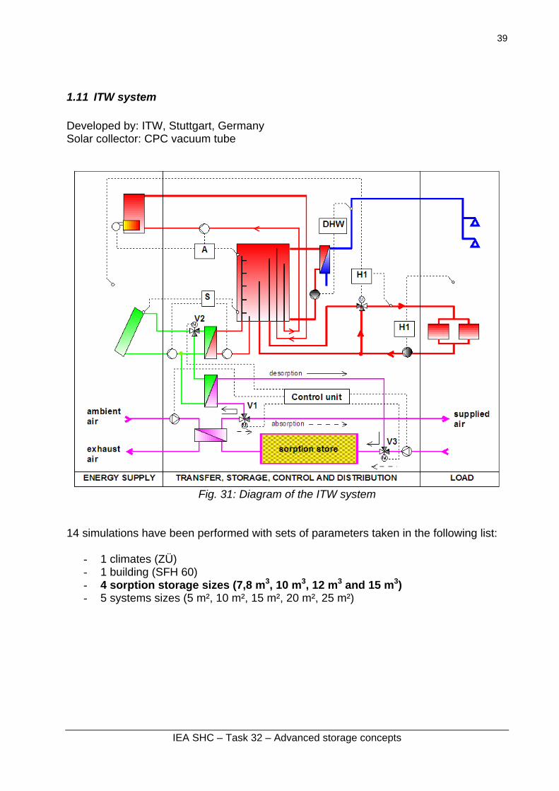
1.11 ITW system Developed by: ITW, Stuttgart, Germany Solar collector: CPC vacuum tube
Fig. 31: Diagram of the ITW system
14 simulations have been performed with sets of parameters taken in the following list:
Fig. 32: Fsav = f(FSC') curves for the ITW system,
with a storage ratio of 56 and 111 kWh/m2 collector.
IEA SHC – Task 32 – Advanced storage concepts
41
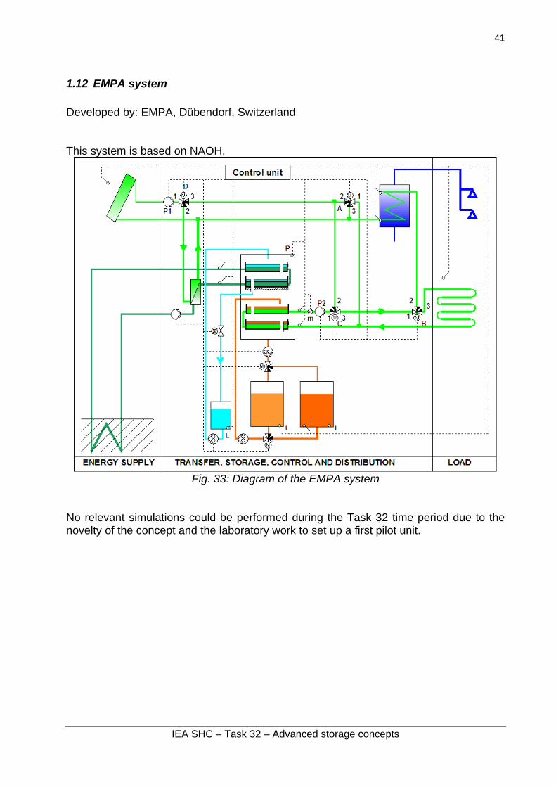
1.12 EMPA system Developed by: EMPA, Dübendorf, Switzerland This system is based on NAOH.
Fig. 33: Diagram of the EMPA system
No relevant simulations could be performed during the Task 32 time period due to the novelty of the concept and the laboratory work to set up a first pilot unit.
IEA SHC – Task 32 – Advanced storage concepts
42
1.13 TCA system Developed by: Climatewell, Sweden and SERC Borlänge, Sweden Main features: The basic process is a batch process, with separate charge (desorption) and discharge (absorption) phases. Figure 34 shows the schematic of a TCA unit, where the solution is pumped over a heat exchanger in the reactor via a spreader to increase the wetted area and improve heat transfer. Water is desorbed from the solution during charging and the solution comes closer and closer to saturation. When it reaches saturation point further desorption at the heat exchanger results in the formation of solid crystals that fall under gravity into the vessel. Here they are prevented from following the solution into the pump by a sieve, thus forming a form of slurry in the bottom of the vessel. For discharging, where the process is reversed, saturated solution is pumped over the heat exchanger where it absorbs the vapour evaporated in the evaporator. The heat of evaporation is provided either by the building (cooling mode) or from the environment (heating mode). The solution becomes unsaturated on the heat exchanger, but when it falls into the vessel it has to pass through the slurry of crystals, where some of the crystals are dissolved to make the solution fully saturated again. In this way the solution is always saturated and the net result is a dissolving of the crystals into saturated solution. The heat of condensation and binding energy release is transferred to the environment (cooling mode) or to the building (heating mode).
IEA SHC – Task 32 – Advanced storage concepts
43
Fig. 34: Diagram of the TCA system A great deal of optimisation based on detailed simulations has been performed on this system prior to Task 32 comparison activity. No simulations could be made during the time of the comparison with Task 32 framework.
IEA SHC – Task 32 – Advanced storage concepts
44
Conclusions All systems studied within IEA SHC Task 32 have been presented in a similar schematic diagram in order to facilitate comparisons. In the course of IEA SHC Task 26 “Solar combisystems”, the FSC method developed in this framework revealed to be fruitful for evaluating the performances of solar combisystems with very different conditions of climates, loads and system sizes. However a limitation of this method was that it could be handled only "small" systems, ie systems without long term storage. For the special purposes of IEA SHC Task 32 dealing with all kind of storages, either small or large, a so-called extended “FSC'” method was developed in Subtask A. This new method has been used in this report to evaluate systems with very different designs. It has proved to be useful for the purpose of describing the performance of a combisystems with any storage size. Several systems with advanced storage techniques have been simulated by Task 32 participants with the Task framework and the simulation models developed throughout the 4 years of the Task. The framework proved to work well. Each simulated system can be referenced with its characteristic curve Fsav vs FSC’ which is independent of the climate and the load ! Task 32 reached its goal to simulate several advanced storage concepts in a combisystem with the same framework The tools to optimise the concepts are now available. The intercomparison of the new storage concepts presented in this report is available in report A4.
IEA SHC – Task 32 – Advanced storage concepts
45
References
Hadorn J-C. (2007) : Method and comparison of storage concepts, A Report of IEA Solar Heating and Cooling programme - Task 32 Advanced storage concepts for solar and low energy buildings, Report A4 of Subtask A, December 2007, 13 p. Heimrath R., Haller M. (2007): The Reference Heating System, the Template Solar System, A Report of IEA SHC - Task 32 Advanced storage concepts for solar and low energy buildings, Report A2 of Subtask A, May 2007, 55 p Letz T. (2003): Validation and Background Information on the FSC Procedure, A Report of IEA SHC - Task 26 Solar Combisystems, December 2002, 23 p Letz T. (2007): The extended FSC procedure for larger storage sizes, A Report of IEA SHC - Task 32 Advanced storage concepts for solar and low energy buildings, Report A1 of Subtask A, December 2007, 26 p All reports of Task 32 are available on: www.iea-shc.org


![Advanced Solar combisystems - DTU Research Databases PhD thesis.pdf · VI Nomenclature A Heat transfer area, [m²] c p Specific heat capacity of water, [J/kgK] A h Total horizontal](https://static.documents.pub/doc/80x56/5ecdf87f08634901be1f434b/advanced-solar-combisystems-dtu-research-database-s-phd-vi-nomenclature-a-heat.jpg)


