Periodic nonsinusoidal vibration: effects in matched filtering for detection of signals buried in noise of uniform spectral density K. Singh and P. C. Gupta In the present paper, the effects of periodic nonsinusoidal vibrations of spatial filters in signal detection experiments are considered. Performance degradation of such an optical information processing system is * shown graphically, assuming that the signal is buried in noise of uniform spectral density. Results are compared with those in the presence of pure sinusoidal vibrations of the spatial filter. It is observed that the performance of the system decreases with the increase in departure from the pure sinusoidal case. 1. Introduction Coherent optical spatial filtering finds applica- tionsl- 5 in character recognition and detection of sig- nals buried in noise; restoration and enhancement of images; removal of noise due to laser speckle and photographic grains; processing of geophysical, radar, and medical data; and carrying out numerous mathe- matical operations. Detection of a known signal within a noisy background by matched filtering is probably the most commonly practiced optical data processing operation. In this technique, the Fourier transform of the input scene is modified by a holographically pro- duced complex spatial filter placed in the back focal plane of the transform lens. The bright peaks in the back focal plane of the retransforming lens define the position of the signal to be detected. To achieve the full potential of the filtering operation, the filter should be placed in its optimum position relative to the spatial frequency spectrum. Any misalignment of the spatial filter will certainly degrade the perfor- mance of the system. Effects of static displacements of the filter normal or parallel to the optical axis on the performance of the system have been treated by Vander Lugt.7 The necessity of optimum placement of the filter has also been stressed by Treves et al." and Yatagai et al. 9 When this work was done, both authors were with the Indian In- stitute of Technology, Physics Department, New Delhi-110029, India; P. C. Gupta is now with the Indian Institute of Technology, Advanced Center for Electronic Systems, Kanpur-208016. Received 19 February 1974. Generally for an optical data processing setup, vi- bration isolation is necessary because, similar to dis- placement, vibration of the filter would also degrade the performance of the system. In spite of the many vibration isolation techniques that are used, there is always some amount of residual vibration present- especially in spacecraft and satellite-borne systems.1 0 Vibrations of the filter can-occur normal or parallel to the optical axis, and in actual conditions the vibra- tions may not be strictly sinusoidal. In some cases they may be nonsinusoidal, though periodic. It is in- teresting to evaluate the performance of the system under such conditions, and this is the aim of the present paper. It has been assumed that the noise spectral density is uniform. These considerations are important mainly if optical processors are to be employed on spacecraft for earth resource observa- tion or space exploration in the future. II. Theory A. Preliminary Considerations The optical data processing system 7 used for the matched filtering operation is shown in Fig. 1. Here lens L 1 collimates the spatially coherent monochro- matic light from source S. Lens L 2 , placed at some distance from L, produces the Fourier transform X(p,q) at the back focal plane P 2 of the input data X 0 (x,y) placed in plane P, between L 2 and P 2 . [It is assumed that the noise is additive, so X 0 (x,y) = S 0 (x,y) + N.(x,y), where Sj(x,y) is the signal and N 0 (x,y) is the noise.] For the matched filtering operation, the spatial fil- ter having complex transmittance H(p,q) is placed in the plane P 2 to modify the spectrum X(p,q). Lens L 2 takes a Fourier transform of X(pq)H(p,q) and displays it in plane P 3 as y (u,v), i.e., 2940 APPLIED OPTICS / Vol. 14, No. 12 / December 1975
Transcript
Periodic nonsinusoidal vibration: effects in matchedfiltering for detection of signals buried in noise of uniformspectral density
K. Singh and P. C. Gupta
In the present paper, the effects of periodic nonsinusoidal vibrations of spatial filters in signal detectionexperiments are considered. Performance degradation of such an optical information processing system is
* shown graphically, assuming that the signal is buried in noise of uniform spectral density. Results arecompared with those in the presence of pure sinusoidal vibrations of the spatial filter. It is observed thatthe performance of the system decreases with the increase in departure from the pure sinusoidal case.
1. Introduction
Coherent optical spatial filtering finds applica-tionsl-5 in character recognition and detection of sig-nals buried in noise; restoration and enhancement ofimages; removal of noise due to laser speckle andphotographic grains; processing of geophysical, radar,and medical data; and carrying out numerous mathe-matical operations. Detection of a known signalwithin a noisy background by matched filtering isprobably the most commonly practiced optical dataprocessing operation.
In this technique, the Fourier transform of theinput scene is modified by a holographically pro-duced complex spatial filter placed in the back focalplane of the transform lens. The bright peaks in theback focal plane of the retransforming lens define theposition of the signal to be detected. To achieve thefull potential of the filtering operation, the filtershould be placed in its optimum position relative tothe spatial frequency spectrum. Any misalignmentof the spatial filter will certainly degrade the perfor-mance of the system. Effects of static displacementsof the filter normal or parallel to the optical axis onthe performance of the system have been treated byVander Lugt.7 The necessity of optimum placementof the filter has also been stressed by Treves et al."and Yatagai et al. 9
When this work was done, both authors were with the Indian In-stitute of Technology, Physics Department, New Delhi-110029,India; P. C. Gupta is now with the Indian Institute of Technology,Advanced Center for Electronic Systems, Kanpur-208016.
Received 19 February 1974.
Generally for an optical data processing setup, vi-bration isolation is necessary because, similar to dis-placement, vibration of the filter would also degradethe performance of the system. In spite of the manyvibration isolation techniques that are used, there isalways some amount of residual vibration present-especially in spacecraft and satellite-borne systems.10Vibrations of the filter can-occur normal or parallelto the optical axis, and in actual conditions the vibra-tions may not be strictly sinusoidal. In some casesthey may be nonsinusoidal, though periodic. It is in-teresting to evaluate the performance of the systemunder such conditions, and this is the aim of thepresent paper. It has been assumed that the noisespectral density is uniform. These considerationsare important mainly if optical processors are to beemployed on spacecraft for earth resource observa-tion or space exploration in the future.
II. Theory
A. Preliminary Considerations
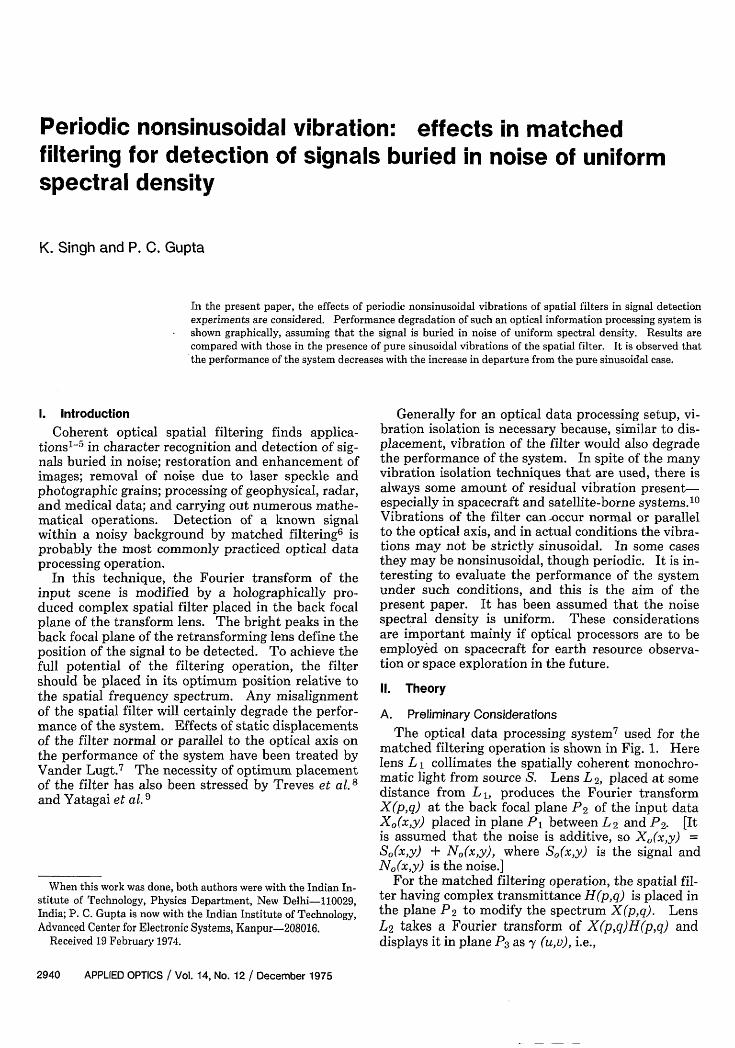
The optical data processing system7 used for thematched filtering operation is shown in Fig. 1. Herelens L 1 collimates the spatially coherent monochro-matic light from source S. Lens L 2, placed at somedistance from L, produces the Fourier transformX(p,q) at the back focal plane P2 of the input dataX 0 (x,y) placed in plane P, between L2 and P2. [Itis assumed that the noise is additive, so X0 (x,y) =S0 (x,y) + N.(x,y), where Sj(x,y) is the signal andN0 (x,y) is the noise.]
For the matched filtering operation, the spatial fil-ter having complex transmittance H(p,q) is placed inthe plane P 2 to modify the spectrum X(p,q). LensL2 takes a Fourier transform of X(pq)H(p,q) anddisplays it in plane P3 as y (u,v), i.e.,
The spatial frequency coordinates (p,q) are relatedto the distance coordinates (go) in plane P2 by therelations
p = kSF, q = k7n/F, (2)
where k = 2/X ( is the wavelength of monochro-matic radiations used and X is the distance betweenplanes P1 and P2).
Furthermore, it has been shown61 1 that for thematched filtering operation in the presence of addi-tive noise the spatial filter H(p,q) should be of theform
H(p,q) = [CS*(p,q)]1/[N(p,q)|2 ], (3)
where S(p,q) is the Fourier transform of the signal tobe detected, I N(p,q)l 2 is the noise spectral density, Cis a constant chosen to make |H(p,q)l < 1 and the as-terisk denotes a conjugate.
In what follows, only one-dimensional notationswill be used as this simplifies the analysis withoutloss of any important results. Let us now assumethat the filter is under vibrations defined by m(t).Equation (1) in one-dimensional notation then be-comes
Using the treatment given by Vander Lugt,7 it can beshown that for the case of uniform noise .the systemperformance (defined as signal-to-noise ratio in theoutput plane P3 normalized to unity for optimumconditions) may be expressed as
P [ iSo(x) 2M(x)dX! 2]/[j SO(X) |dxj 21, (5)
where M(x), known as characteristic function of mo-tion is given by,
M(x) = Limn4f exp[-jxm(t)]dt. (6)T- fo
Here T is the detection time over which an integrat-ing physical detector in the output plane P3 is opera-tive.
B. Effect of Vibrations
1. Transverse Vibrations
Assume that the spatial filter is vibrating nonsinu-soidally, perpendicular to the optical axis, with am-plitude p and angular frequency w, with the equa-tion of motion as
m(t) = psn(wt/n). (7)
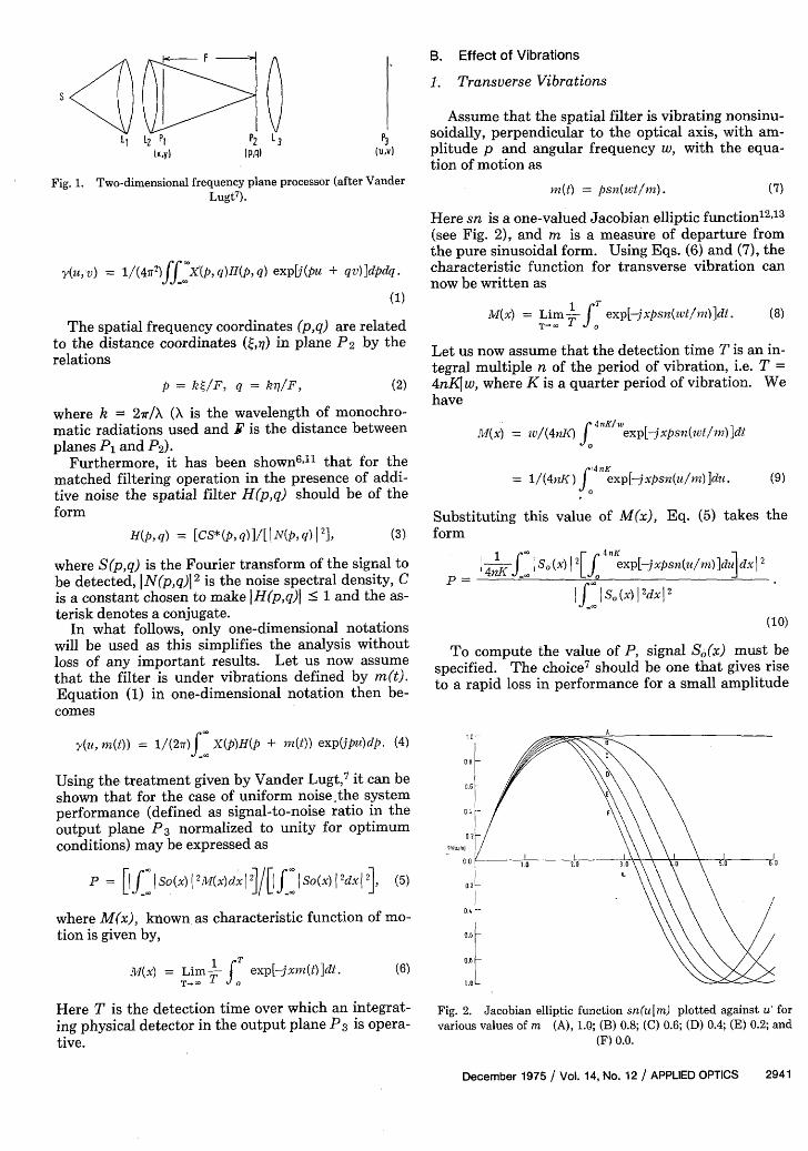
Here sn is a one-valued Jacobian elliptic function12"13
(see Fig. 2), and m is a measure of departure fromthe pure sinusoidal form. Using Eqs. (6) and (7), thecharacteristic function for transverse vibration cannow be written as
M((x) = Lim f exp[jxpsn(wt/1n)]dt. (8)
Let us now assume that the detection time T is an in-tegral multiple n of the period of vibration, i.e. T =4nK w, where K is a quarter period of vibration. Wehave
M(x = w/(4nK) exp[-jxpsn(wt/m)]dt
= 1/(4nK) f 4 exp[-jxpsn(u/m) ]du. (9)0
Substituting this value of M(x), Eq. (5) takes theform
4K f X S0(X) I 2[f 4 exp[jxpsn(u/m)]duldx|
If IS.(x) l2dxl2
(10)
To compute the value of P,specified. The choice7 shouldto a rapid loss in performance
signal S(x) must bebe one that gives risefor a small amplitude
°°0 A . .\ .
0.6
0.?'
0.4-
1.0 _
Fig. 2. Jacobian elliptic function sn(ulm) plotted against u forvarious values of m (A), 1.0; (B) 0.8; (C) 0.6; (D) 0.4; (E) 0.2; and
X' be the distance through which a signal is displacedfrom the optical axis. Suppose at some instant dur-ing vibration, the filter is displaced from the spatialfrequency plane P2 by an amount Z. Since the cen-ter of the spectrum of the signal passes through thefrequency plane at the optical axis, it is displacedfrom the axis by an amount 40 when it reaches the fil-ter plane. Here
Fig. 3. Diagram for analyzing effect of longitudinal vibrations(after Vander Lugt7).
of vibrations. Further, the signal should be of finiteextent and should have unity as its maximum value.This can be realized by maximizing the derivative ofP for small p. Under the given constraints this ispossible only if ISo(x) 1 2 = 1, for 0 x L and zeroelsewhere. Here L is the length of the signal. Equa-tion (10) now takes the form
P X 1 Ju 1 4 4nK exp[-xsn(u/n)]dudx 2.11)
The function sn(uIm) can be expanded' 4 to the form
snu 2K[sin(iru)/(2I•)
+ 4 2sBy sin(2s - 1)(2K ), (12)
where q(m) is called the nome of the function. Sub-stituting this value of sn(u I m) Eq. (11) now becomes
P = PL (I exp -
I (in Xl
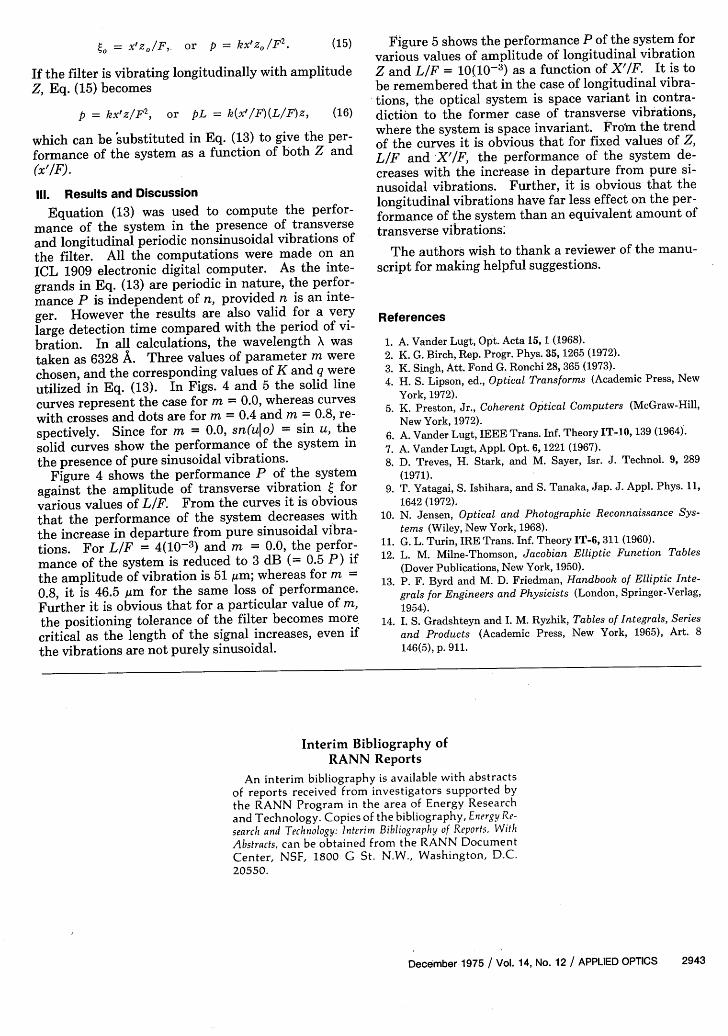
Fig. 4. Performance parameter P vs amplitude of transverse vi-brations 4 for various values of LIF: (1) 2(10-3); (2) 4(10-3); (3)
10(10-3); (4) 20(10-3); (5) 50 (10-3); and (6) 100 (10-3).
1.0I
[sin(2n7Tu)
2Kx/rSs i+ 4 Z 1 2is.. sin(2s -
To compute the performance frompress spatial frequency variable ptance variable from Eq. (2) so
]du dxI2..1)(2nu)jl
(13)
Eq. (13), we ex-in terms of dis-
(14)
where is now the physical amplitude of vibrationand (LIE) is a dimensionless ratio.
2. Longitudinal VibrationsWhen the spatial filter is vibrating longitudinally,
the effect on the performance of the system can beevaluated in the same way as the effect of transversevibrations. Since the length of the signal is muchless than the distance F the Fourier transform of thesignal is a slowly varying function of displacementfrom frequency plane P2; and the effect of longitudi-nal vibrations can be analyzed by referring to Fig. 3.Let 2A' be the length of the aperture in plane P and
Fig. 5. Performance parameter P vs X'/F, for LIF = 10(10-3)and various values of Z: (1) 150 ,um; (2) 300 Aim; (3) 600 gim; (4)
If the filter is vibrating longitudinally with amplitudeZ, Eq. (15) becomes
p = kx'z/F 2 , or L = k(x'/F)(L/F)z, (16)
which can be substituted in Eq. (13) to give the per-
formance of the system as a function of both Z and(x'/F).
111. Results and Discussion
Equation (13) was used to compute the perfor-mance of the system in the presence of transverseand longitudinal periodic nonsinusoidal vibrations ofthe filter. All the computations were made on anICL 1909 electronic digital computer. As the inte-grands in Eq. (13) are periodic in nature, the perfor-mance P is independent of n, provided n is an inte-
ger. However the results are also valid for a very
large detection time compared with the period of vi-bration. In all calculations, the wavelength X wastaken as 6328 A. Three values of parameter m werechosen, and the corresponding values of K and q wereutilized in Eq. (13). In Figs. 4 and 5 the solid line
curves represent the case for m = 0.0, whereas curves
with crosses and dots are for m = 0.4 and m = 0.8, re-
spectively. Since for m = 0.0, sn(uIo) = sin u, the
solid curves show the performance of the system inthe presence of pure sinusoidal vibrations.
Figure 4 shows the performance P of the systemagainst the amplitude of transverse vibration t forvarious values of LIF. From the curves it is obviousthat the performance of the system decreases withthe increase in departure from pure sinusoidal vibra-tions. For LIF = 4(10-3) and m = 0.0, the perfor-mance of the system is reduced to 3 dB (= 0.5 P) ifthe amplitude of vibration is 51 gim; whereas for m =
0.8, it is 46.5 Am for the same loss of performance.Further it is obvious that for a particular value of m,
the positioning tolerance of the filter becomes morecritical as the length of the signal increases, even ifthe vibrations are not purely sinusoidal.
Figure 5 shows the performance P of the system forvarious values of amplitude of longitudinal vibrationZ and LIF = 10(10-3) as a function of X'/F. It is tobe remembered that in the case of longitudinal vibra-tions, the optical system is space variant in contra-diction to the former case of transverse vibrations,where the system is space invariant. Frown the trendof the curves it is obvious that for fixed values of Z,LIF and X'/F, the performance of the system de-creases with the increase in departure from pure si-nusoidal vibrations. Further, it is obvious that thelongitudinal vibrations have far less effect on the per-formance of the system than an equivalent amount oftransverse vibrations;
The authors wish to thank a reviewer of the manu-script for making helpful suggestions.
References
1. A. Vander Lugt, Opt. Acta 15, 1 (1968).
2. K. G. Birch, Rep. Progr. Phys. 35, 1265 (1972).
3. K. Singh, Att. Fond G. Ronchi 28, 365 (1973).
4. H. S. Lipson, ed., Optical Transforms (Academic Press, New
York, 1972).5. K. Preston, Jr., Coherent Optical Computers (McGraw-Hill,
New York, 1972).6. A. Vander Lugt, IEEE Trans. Inf. Theory IT-10, 139 (1964).
7. A. Vander Lugt, Appl. Opt. 6, 1221 (1967).
8. D. Treves, H. Stark, and M. Sayer, Isr. J. Technol. 9, 289
(1971).9. T. Yatagai, S. Ishihara, and S. Tanaka, Jap. J. Appl. Phys. II,
1642 (1972).10. N. Jensen, Optical and Photographic Reconnaissance Sys-
tems (Wiley, New York, 1968).11. G. L. Turin, IRE Trans. Inf. Theory IT-6, 311 (1960).
12. L. M. Milne-Thomson, Jacobian Elliptic Function Tables
(Dover Publications, New York, 1950).
13. P. F. Byrd and M. D. Friedman, Handbook of Elliptic Inte-
grals for Engineers and Physicists (London, Springer-Verlag,1954).
14. I. S. Gradshteyn and I. M. Ryzhik, Tables of Integrals, Series
and Products (Academic Press, New York, 1965), Art. 8
146(5), p. 911.
Interim Bibliography ofRANN Reports
An interim bibliography is available with abstractsof reports received from investigators supported bythe RANN Program in the area of Energy Researchand Technology. Copies of the bibliography, Energy Re-search and Technology: Interim Bibliography of Reports, With
Abstracts, can be obtained from the RANN DocumentCenter, NSF, 1800 G St. N.W., Washington, D.C.20550.