28
I © The Switch 2011 1 PERMANENT MAGNET MATERIAL PROPERTY CRITERIA IN WIND POWER APPLICATION 14th of June 2012
I © The Switch 2011 1
PERMANENT MAGNET MATERIAL PROPERTY
CRITERIA IN WIND POWER APPLICATION 14th of June 2012

I © The Switch 2011 2
CONTENTS
The Switch
Turbine technology
Generator types
PMG rotor designs for WP
Demagnetization risk
Usage of magnets in different generator types
Other requirements for magnetic circuit in
generators
Cost reduction options

I © The Switch 2011 3
“We are setting the standard for modern drive train
technology. Currently, we are in close to 20 wind turbine designs and are building the capacity for them.”
– Jukka-Pekka Mäkinen,
President and CEO
BUSINESS
3 I © The Switch 2011
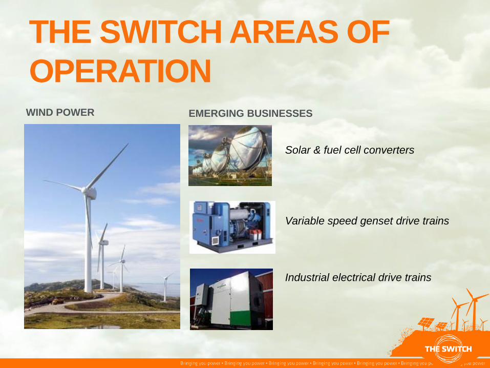
WIND POWER EMERGING BUSINESSES
Solar & fuel cell converters
Variable speed genset drive trains
Industrial electrical drive trains
THE SWITCH AREAS OF
OPERATION

I © The Switch 2011 5
THE SWITCH DRIVE™
The soul of every reliable wind turbine
I © The Switch 2011 5 I © The Switch 2011
I © The Switch 2011 6
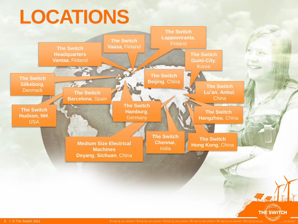
LOCATIONS
The Switch
Hudson, NH,
USA
The Switch
Headquarters
Vantaa, Finland
The Switch
Beijing, China The Switch
Lu’an, Anhui,
China
Medium Size Electrical
Machines
Deyang, Sichuan, China
The Switch
Lappeenranta,
Finland The Switch
Vaasa, Finland
The Switch
Chennai,
India
The Switch
Gumi-City,
Korea
The Switch
Hong Kong, China
The Switch
Hangzhou, China
The Switch
Barcelona, Spain
The Switch
Hamburg,
Germany
The Switch
Silkeborg,
Denmark
6 I © The Switch 2011

WIND TURBINE
Turbine automation
• Yaw control
• Pitch control
• Speed control
• Torque control
Electric drive
• Traditional wind turbine:
Gear + high speed IM
• Direct drive without gear
Source:http://windeis.anl.gov/guide/basics/turbine.html

AN EXAMPLE
1. Cooler
2. Generator
3. Automation
4. Anemometer
5. Coupling
6. Mechanical brake
7. Gearbox
8. Main shaft
9. Yaw gear
10. Machine bed
11. Main bearing
12. Hub control
13. Pitch controller
14. Blade
Source: Vestas V82-1.65 MW broshure

TYPICAL POWER CURVE:
V82-1.65 MW
Source: Vestas V82-1.65 MW broshure

GENERATOR OPTIONS
Double fed induction generator
Directly net coupled induction machine
Electrically excited synchronous generator Permanent magnet synchronous generator

PRODUCT PORTFOLIO POWER
SPEED
1.0
2.0
3.0
4.0
5.0
6.0
LOW MEDIUM 1500 1000
3.3 MW/13 rpm
4.25 MW/16 rpm
1.65 MW/17 rpm
1.65 MW/120 rpm
3.3 MW/136 rpm
1.65 MW/150 rpm
5.9 MW/1100rpm
5.6 MW/1200rpm
3.3 MW/1000 rpm
3.3 MW/1500 rpm
2.7 MW/1000 rpm 2.7 MW/1500 rpm
2.2 MW/1500 rpm 2.2 MW/1000 rpm
1.6 MW/1000 rpm 1.6 MW/1500 rpm
1.1 MW/1000 rpm 1.1 MW/1500 rpm
3.2 MW/414 rpm
1.4 MW/292 rpm
3.3 MW/365 rpm
FD: 3.2 MW/346 rpm

I © The Switch 2011 12
Options GENERATOR CONSTRUCTION
HS DD MS In standard platform
Option
Turbine
technology
Low-speed/
Direct driven
Medium-
speed
High-speed
Machine
construction
Inner rotor
Outer rotor
Cooling
arrangement
IP 54
Air/air
IP54
Air/water
IP23
Magnet
assembly
Surface-mounted
magnet modules
Surface-mounted
magnets
Embedded
magnets
Winding
Random
wound
Form
wound
Litz
wire
Voltage
Low voltage
Medium
voltage

DIRECT-DRIVE GENERATORS
• Increasing efficiency towards partial loads
• Best overall drive-train efficiency
• No gearbox, no fast-rotating parts
→ Increased reliability
• Highest torque density due to large cooling area in active parts
• Mechanical interface design for turbine in co-operation with turbine
designer
• Generator bearing can act as a turbine main bearing
• Large generator size due to high torque
• Possibility to integrate break system to generator construction
kW
86
88
90
92
94
96
0 1000 2000 3000 4000 5000
Eff
icie
nc
y (
%)

DIRECT-DRIVE GENERATORS
1.65 MW direct-drive outer rotor
Generator Frame size: 2250
3.3 MW, 13 rpm direct-drive outer rotor
generator. Frame size: 3000
Outer rotor generators
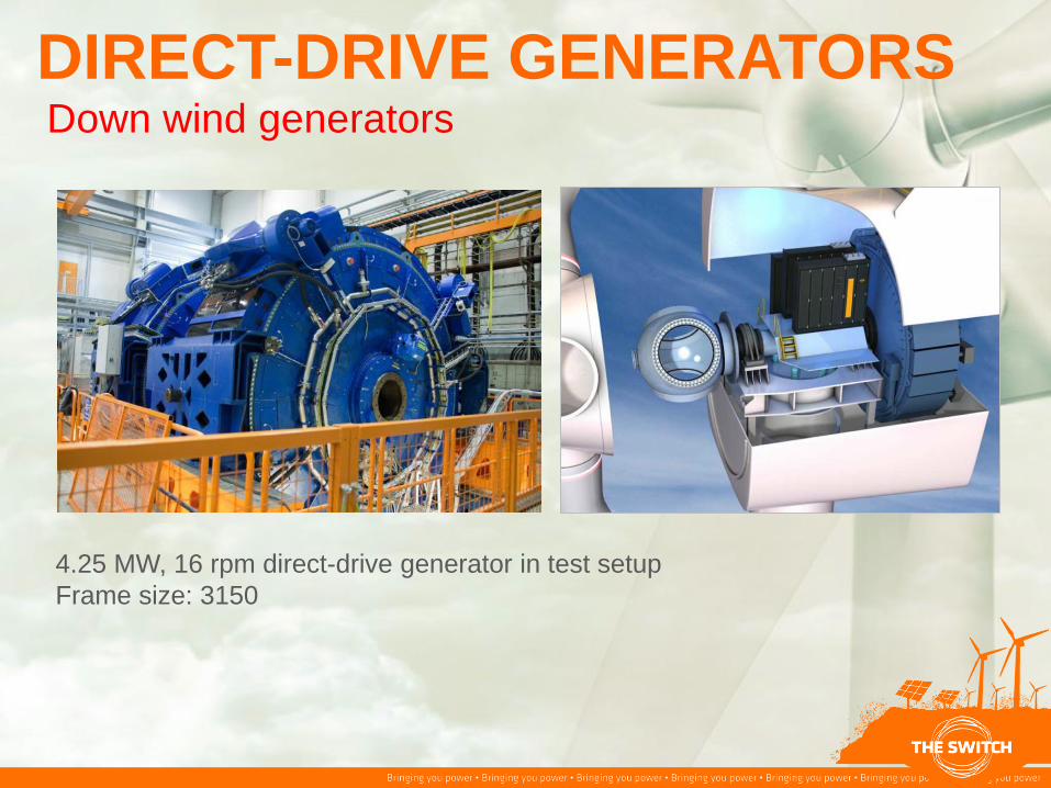
DIRECT-DRIVE GENERATORS
4.25 MW, 16 rpm direct-drive generator in test setup
Frame size: 3150
Down wind generators

GEARED GENERATORS
• 1- or 2-stage gearbox
• Generator speed is usually 100 to 500 rpm
• Typically flange mounting between generator
and gearbox
• Integrated drive train with a simplified
structural design (FusionDrive®)
• Lowest nacelle weight
• Improved total turbine cost effectiveness
Medium speed generators
High-speed generators
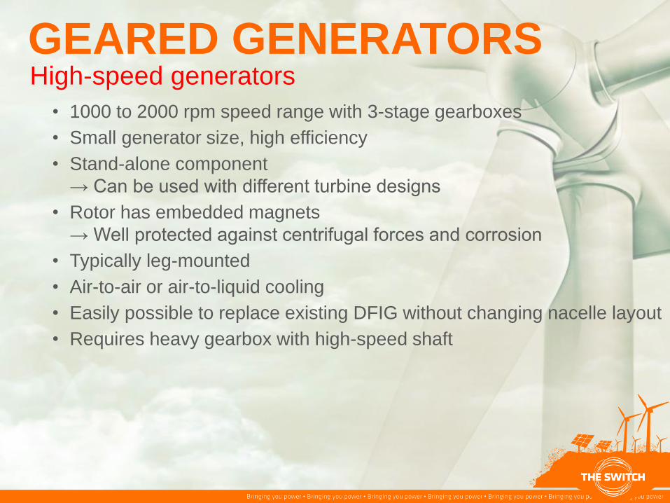
GEARED GENERATORS
• 1000 to 2000 rpm speed range with 3-stage gearboxes
• Small generator size, high efficiency
• Stand-alone component
→ Can be used with different turbine designs
• Rotor has embedded magnets
→ Well protected against centrifugal forces and corrosion
• Typically leg-mounted
• Air-to-air or air-to-liquid cooling
• Easily possible to replace existing DFIG without changing nacelle layout
• Requires heavy gearbox with high-speed shaft
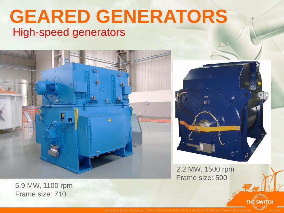
GEARED GENERATORS
5.9 MW, 1100 rpm
Frame size: 710
2.2 MW, 1500 rpm
Frame size: 500
High-speed generators

ROTOR DESIGN
• For direct –drive
• and medium-speed generators:
• → Allow the maximum power to be captured from the magnet
• Maximum flux in air gap
• Typically protected with a module construction (hermetically sealed)
• Must be firmly fastened against centrifugal forces
Magnet modules in an outer rotor
direct-drive generator
3.3 MW medium-speed
generator
Surface mounted magnets

ROTOR DESIGN
• For high-speed generators:
• Magnets are built inside a sealed corrosion-resistant metal enclosure
• No threat due to centrifugal forces
• Hermetic sealing provides protection from the environment
(rotor is impregnated)
• Tangentially multiple magnets / pole
3.3 MW high-speed generator rotor
Embedded magnets

Magnet grade
Most critical raw materials:
Neodymium (Nd) mainly to increase remanence flux (together with
Praseodym; PrNd ~50 €/kg (5/2012)
Dysprosium (Dy) to increase coersivity (demag. resistance); FeDy
~550 €/kg
Terbium (Tb) to increase coersivity; ~1200 €/kg
Grade Dy PrNd Tb Typical use
4X SH 3...4 % 26...27 % 0 Direct drive
40 UH 5...6 % 25...26 % 1...2 % Medium speed
38 EH 3...4 % 24...25 % 2...3 % High-speed

Raw material sources outside China Case study with nine mines / known recourses
Mine Country Location Company
1 Australia Dubbo Alkane Recources Ltd
2 Australia Nolans Arafura Recources Ltd
3 Canada Nechalacho Avalon Rare Metals Inc
4 Canada Hoidas lake Great Western Minerals Group
5 South Africa Steenkampakraal Great Western Minerals Group
6 Greenland Kvaenefjeld Greenland Minerals & Energy Ltd
7 Australia Mt. Weld Lynas
8 USA / Ca Mt. Pass Molycorp Minerals LLC
9 USA / Wo Bear Lodge Rare Element Recources Ltd
RE recources in 9 mines (kton):
3 MW PMG consumes RE-materials (not magnets):
- Direct Drive 800 kg
- Medium speed 130 kg
- High speed 80 kg
Pr 489
Nd 1606
Tb 20
Dy 104
Sum 2220
DD MS HS
PrNd 8980 56125 114292 GW
Dy 2628 16425 12483 GW
Generator capasity built with 9 mines recources:

Demagnetization Magnet grade is selected based on the demagnetization
calculation
External field
Rotor temperature
Typical factors
Rated frequency / speed (HS worst – DD easiest)
Air-gap length
Tangential tention
4MAGNETS_MOD1
-250
0
250
100 200 300
mm
(E-3) Tesla
CURVE C2D_13Flux density / Normal componentPath_5 Time (s.) : 0,038
TOIM_P12_NL
-200
-99,999
0
100
200
300
0 50 100
mm
(E-3) Tesla
CURVE C2D_5Flux density / Normal componentPath_1 Time (s.) : 26,1E-3
3PH_SC_HOT
200
300
400
500
600
700
0 50 100
mm
(E-3) Tesla
CURVE C2D_232Flux density / Normal componentPath_1 Time (s.) : 184,799999E-3
HS
MS
DD
Critical level 100 °C
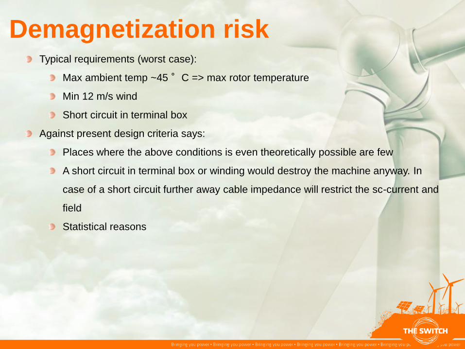
Demagnetization risk Typical requirements (worst case):
Max ambient temp ~45 °C => max rotor temperature
Min 12 m/s wind
Short circuit in terminal box
Against present design criteria says:
Places where the above conditions is even theoretically possible are few
A short circuit in terminal box or winding would destroy the machine anyway. In
case of a short circuit further away cable impedance will restrict the sc-current and
field
Statistical reasons

Other typical requirements in WP Life time 25 years (< 2% flux reduction)
< 1% ( or even < 0.5 %) cogging
Magnet shape
Skewing
Rotor
Stator
Forming Air-gap shape
Asymmetry
Rotor poles
Stator slots
IP54 construction (rotor typically requires air circulation for cooling)
Sea environment (salt)

REDUCING MAGNET GRADE (COST) BY
DIRECT COOLING WITH INPUT FILTER
Typical requirement IP54 =>
Water jacket (+ air circulation)
Internal air circualtion + heat exchanger
Replace HEX with Goretex filter and exhaust pipe
10...15 °C cooler air for cooling => upgrade or lower grade
magnets
Is applicable for symmetric or asymmetric cooling arrangement
Filter has to be changed every 3...5 years
Is not real IP54
Requires change of thinking
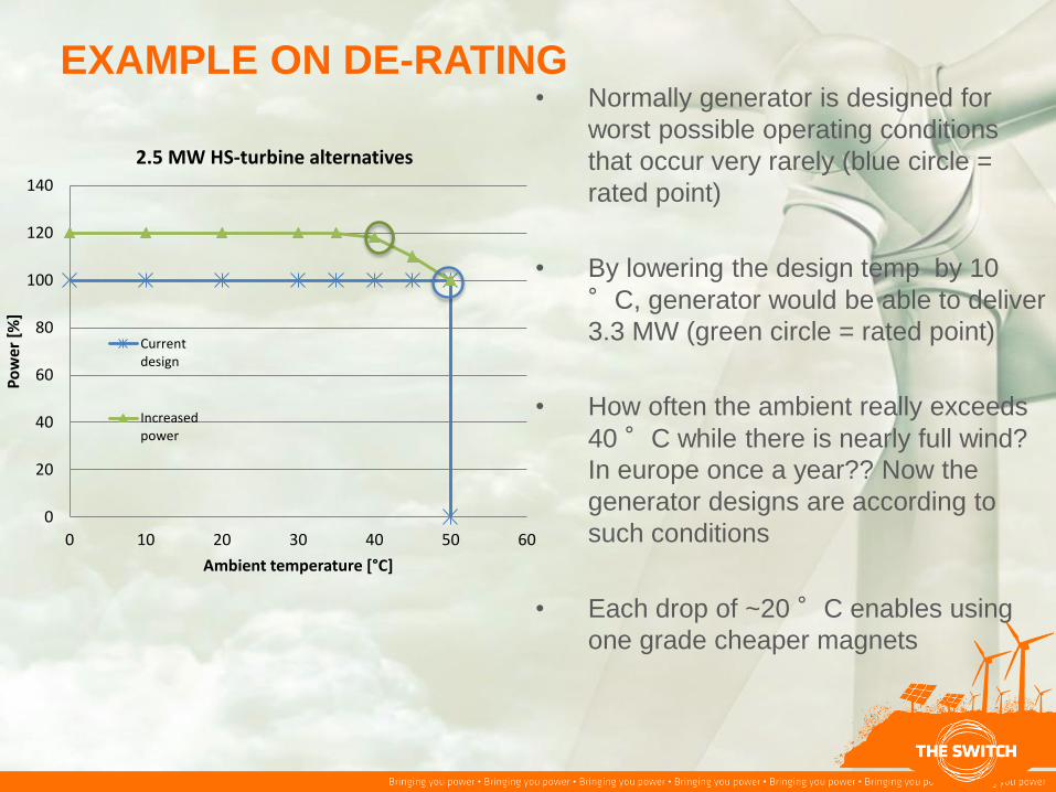
EXAMPLE ON DE-RATING • Normally generator is designed for
worst possible operating conditions
that occur very rarely (blue circle =
rated point)
• By lowering the design temp by 10
°C, generator would be able to deliver
3.3 MW (green circle = rated point)
• How often the ambient really exceeds
40 °C while there is nearly full wind?
In europe once a year?? Now the
generator designs are according to
such conditions
• Each drop of ~20 °C enables using
one grade cheaper magnets
0
20
40
60
80
100
120
140
0 10 20 30 40 50 60
Po
wer
[%
]
Ambient temperature [°C]
2.5 MW HS-turbine alternatives
Currentdesign
Increasedpower

I © The Switch 2011 28
Äyritie 8 C
FI-01510 Vantaa, Finland
Tel +358 20 783 8200
Fax +358 20 783 8570
Thank You


