105


Permanent P&A – An identification and discussion of technologies and differences in UKCS and NCS regulations
PERMANENT PLUGGING
AND ABANDONMENT – An identification and discussion of
technologies and the differences in UKCS and
NCS regulations
Anne Lene Blom Øksnes

Permanent P&A – An identification and discussion of technologies and differences in UKCS and NCS regulations
i
Acknowledgements
I would like to take this opportunity to thank some people who have aided me in writing this thesis.
Firstly, I would like to extend my gratitude to my supervisor at the University of Stavanger, Jostein
Aleksandersen for suggesting a topic and giving me valuable and structured feedback and assistance
during the process of writing my thesis.
I would also like to acknowledge the companies Interwell, Island Offshore and HydraWell for
providing me with the needed insight and information to describe their technologies.
Lastly, I must extend a thank you to my co-students and friends for giving me the needed breaks,
perspective and motivation for finishing this thesis.

Permanent P&A – An identification and discussion of technologies and differences in UKCS and NCS regulations
ii
Abstract
There is a large number of wells on the Norwegian Continental Shelf that need to be permanently
plugged and abandoned (P&A) within the next decades. As P&A does not provide any income, it is
very important to develop cost-effective methods to perform the operations. This thesis gives a brief
presentation of how plug and abandonment operations are performed and which challenges that
exist within the field. Further some selected technologies which are under development or recently
implemented in the industry are presented and discussed. In addition to the technological
challenges, it is also likely that the regulations can play a role in achieving more effective solutions.
The main objective of this thesis has been to analyse the Norwegian standard that is valid for P&A
operations and compare it to both the existing guidelines on the UK continental shelf and to a risk-
based perspective proposed by DNV GL. The UK industry is more experienced than the Norwegian
and operate in similar waters, therefor it makes sense to compare the two to find ways of improving
NORSOK D-010. The risk-based perspective provides a new approach to P&A which is in line with the
overall trends of the industry where risk-based decision making is becoming increasingly emphasised.
The comparison of these three documents resulted in several suggestions for improving the NORSOK
D-010, and for additional guidelines that might be useful on the NCS.
Another aspect of this thesis has been to investigate how new technologies can be used to improve
P&A activities as this is likely to be the main contributor for more cost-efficient operations. The
overall goal of the technologies presented is to eliminate the need for a rig as this is one of the
highest costs in P&A. Also, rigs are better used for drilling where there exists potential revenue for
the operators. Some of the technologies have been implemented whereas others struggle to achieve
qualification and be tested. The industry is conservative and there is a certain reluctance towards
trying new technologies, when there are already solutions that works implemented. This thesis
suggest that part of the problem lies within the phrasing and requirements found in NORSOK D-010
which appears to be very strict.
The result of this thesis is a list of recommendations on how to improve the NORSOK D-010 to close
the gap between UKCS and NCS regulations. It further provides recommendations for how to better
open for alternative technologies and methods to be implemented in P&A operations.

Permanent P&A – An identification and discussion of technologies and differences in UKCS and NCS regulations
iii
Abbreviations
ALARP As Low As Reasonably Practicable
BHA Bottom Hole Assembly
BOP Blow Out Preventer
COP Cessation of Production
CT Coiled Tubing
DCR The offshore installation and wells (design & construction etc) 1996
DPMV Dynamically Positioned Monohull Vessel
HLV Heavy lift vessel
HXT Horizontal x-mas tree
IOSS Island Offshore Subsea
LLP Lower Lubricator Package
LWI Light Well Intervention
MD Measured Depth
MO(D)U Mobile Offshore (Drilling) Unit
OWCT Open Water Coil Tubing
P&A Plug and Abandonment
PSA Petroleum Safety Authority
RLWI Riserless Well Intervention
TOC Top of Cement
VXT Vertical x-mas tree
WL Wireline
XT X-mas tree

Permanent P&A – An identification and discussion of technologies and differences in UKCS and NCS regulations
iv
Table of content
Acknowledgements .................................................................................................................................. i
Abstract .................................................................................................................................................... ii
Abbreviations .......................................................................................................................................... iii
List of figures ........................................................................................................................................... vi
List of tables ........................................................................................................................................... vii
1 Introduction ..................................................................................................................................... 1
1.1 Objectives ................................................................................................................................ 2
1.2 Thesis structure ....................................................................................................................... 2
2 Vessels used in offshore operations ................................................................................................ 3
3 Plug and Abandonment – What it is and how it is done ................................................................. 5
3.1 P&A current status .................................................................................................................. 6
3.2 Procedure for P&A operations ................................................................................................ 6
3.2.1 Killing and securing the well ............................................................................................ 7
3.2.2 Pulling of tubing............................................................................................................... 8
3.2.3 Logging the Cement ......................................................................................................... 8
3.2.4 Removal of wellhead and other equipment above seabed .......................................... 10
3.3 Challenges with P&A ............................................................................................................. 10
3.3.1 Current situation ........................................................................................................... 10
3.3.2 Availability of vessels to perform P&A .......................................................................... 10
3.3.3 Available information about wells and their condition ................................................. 11
3.3.4 Logging of cement ......................................................................................................... 11
3.3.5 Removal of control lines ................................................................................................ 12
3.3.6 Removal of casing to set cement plug........................................................................... 12
3.3.7 Cooperation within market ........................................................................................... 13
3.3.8 Temporarily abandoned wells ....................................................................................... 14
3.3.9 Regulations and requirements ...................................................................................... 14
3.4 New technology ..................................................................................................................... 16
3.4.1 Perforate, wash and cement to establish well barrier .................................................. 16
3.4.2 Alternatives to cement as barrier .................................................................................. 18
3.4.3 Pulling of tubing by using wireline/coiled tubing .......................................................... 20
3.4.4 Interwell rig-less P&A .................................................................................................... 21
3.4.5 Open Water Coiled Tubing ............................................................................................ 22
4 Requirements and Regulations ..................................................................................................... 25
4.1 NORSOK D-010 – Well integrity in drilling and well operations ............................................ 25
Permanent P&A – An identification and discussion of technologies and differences in UKCS and NCS regulations
v
4.1.1 Definitions ..................................................................................................................... 26
4.1.2 Abandonment design .................................................................................................... 26
4.1.3 Well barrier .................................................................................................................... 27
4.1.4 Well barrier element ..................................................................................................... 29
4.1.5 Length requirements ..................................................................................................... 30
4.1.6 Verification .................................................................................................................... 31
4.1.7 Removing equipment above seabed ............................................................................. 32
4.1.8 Well barrier schematics ................................................................................................. 32
4.1.9 Examples of different options for setting the plug ....................................................... 34
4.1.10 Methods to establish cement plug ................................................................................ 35
4.1.11 Other topics ................................................................................................................... 35
4.2 Oil and Gas UK – Guidelines for the abandonment of wells ................................................. 37
4.2.1 Definitions ..................................................................................................................... 37
4.2.2 Material requirements for permanent barriers ............................................................ 38
4.2.3 Zones with flow potential .............................................................................................. 40
4.2.4 Permanent barriers ....................................................................................................... 41
4.2.5 Verification of a permanent barrier .............................................................................. 48
4.2.6 Special considerations for abandonment...................................................................... 50
4.2.7 Phases of well abandonment ........................................................................................ 54
4.2.8 Appendices .................................................................................................................... 55
4.2.9 Guidelines on Well Abandonment Cost Estimation ...................................................... 56
4.3 DNV GL – RP-E103 – Risk based abandonment of offshore wells ......................................... 61
4.3.1 Section 1 – introduction ................................................................................................ 61
4.3.2 Section 2 – Risk assessment framework for well abandonment design ....................... 63
4.4 Matrix summarizing requirements in different documents .................................................. 70
5 Discussion ...................................................................................................................................... 71
5.1 Differences in regulations and guidelines ............................................................................. 71
5.1.1 Structure and intent of the documents ......................................................................... 71
5.1.2 Phrasing/wording used.................................................................................................. 72
5.1.3 Well barriers .................................................................................................................. 72
5.1.4 Materials used as barriers ............................................................................................. 73
5.1.5 Verification of barriers .................................................................................................. 74
5.1.6 Categorization of wells .................................................................................................. 76
5.1.7 Cost Estimation .............................................................................................................. 77
5.2 Considerations of P&A in initial well design .......................................................................... 78
5.3 Incorporation of risk-based perspective ............................................................................... 79

Permanent P&A – An identification and discussion of technologies and differences in UKCS and NCS regulations
vi
5.4 Technological developments ................................................................................................. 81
5.4.1 Cooperation and combinations of technologies ........................................................... 81
5.4.2 The PWC tool ................................................................................................................. 81
5.4.3 The OWCT system and potential combinations ............................................................ 82
5.4.4 Alternatives to cement as barrier .................................................................................. 84
5.4.5 Interwell solution .......................................................................................................... 85
5.5 Eliminating the use of rig in P&A operations ........................................................................ 86
6 Conclusions and recommendations .............................................................................................. 88
6.1 General .................................................................................................................................. 88
6.2 Recommendations for NORSOK D-0101 ............................................................................... 88
6.3 Recommendations for technology and methods .................................................................. 90
References ............................................................................................................................................. 91
Appendix................................................................................................................................................ 93
List of figures
Figure 1: Illustration of different vessel categories [5]. .......................................................................... 4
Figure 2: Simple illustration of a well before and after P&A ................................................................... 6
Figure 3: Simple well barrier schematic .................................................................................................. 9
Figure 4: Section Milling operation [13] ................................................................................................ 13
Figure 5: DNV GL qualification process [16] .......................................................................................... 15
Figure 6: Time saved using PWC compared to Section Milling [17] ...................................................... 16
Figure 7: The HydraWash tool [18] ....................................................................................................... 17
Figure 8: Sandaband yield properties [21] ............................................................................................ 20
Figure 9: Conventional versus open water coiled tubing [32] .............................................................. 23
Figure 10: Challenges for doing P&A from LWI vessels on subsea wells [33] ....................................... 24
Figure 11: Illustration of cross-sectional requirement for permanent well barriers [6] ....................... 28
Figure 12: Permanent abandonment of an open hole and inside casing plugs [6] .............................. 31
Figure 13: Example WBS with EAC referral [6] ...................................................................................... 33
Figure 14: Example of WBSs [6] ............................................................................................................ 34
Figure 15: Examples of different options for setting plugs for permanent abandonment [6] ............. 35
Figure 16: Schematic of permanent barrier [34] .................................................................................. 41
Figure 17: General requirements for well abandonment [34] .............................................................. 42
Figure 18: Illustration of geological setting for permanent barriers [34] ............................................. 43
Figure 19: Length requirements for permanent barriers [34] .............................................................. 44
Figure 20: Open hole P&A where internal pressure is less than casing shoe fracture pressure [34] ... 44
Figure 21: Example of open hole barriers where two zones need isolation from each other but does
not exceed the casing shoe fracture pressure [34] ............................................................................... 45
Figure 22: Example of open hole barrier where potential internal pressure exceeds casing shoe
fracture pressure [34, 36] ...................................................................................................................... 45
Figure 23: Example of side-tracked well with open hole section [34] .................................................. 46
Figure 24: Casing alone is not accepted as lateral permanent barrier [34] .......................................... 47

Permanent P&A – An identification and discussion of technologies and differences in UKCS and NCS regulations
vii
Figure 25: Example of cased hole abandonment [34] ........................................................................... 48
Figure 26: Abandonment of high angle well [34] .................................................................................. 51
Figure 27: Liner lap cementation [34] ................................................................................................... 52
Figure 28: Through-tubing abandonment [34] ..................................................................................... 53
Figure 29: Illustration of cost estimation process [37] .......................................................................... 60
Figure 30: The main system components of P&A wells [39] ................................................................. 63
Figure 31: Risk Context for P&A [39] ..................................................................................................... 64
Figure 32: Examples of well abandonment designs in DNV GL- RP-E103 [39] ...................................... 67
List of tables
Table 1: Applications for open water coiled tubing .............................................................................. 23
Table 2: Well Barriers depth position .................................................................................................... 27
Table 3: Content of well barrier element acceptance criteria tables [6] .............................................. 29
Table 4: Cement plug length requirements [6] ..................................................................................... 30
Table 5: Level of accuracy required as COP approaches [37] ............................................................... 58
Table 6: Matrix for categorizing well abandonment [37] ..................................................................... 59
Table 7: Example of well categorization [37] ........................................................................................ 59
Table 8: Categorization of flow potential in hydrocarbon-bearing formations .................................... 65
Table 9: Matrix summarizing main differences in documents .............................................................. 70

Permanent P&A – An identification and discussion of technologies and differences in UKCS and NCS regulations
1
1 Introduction
When oil and gas offshore fields mature and wells no longer produce enough to be economically
sustainable, even with intervention, the wells eventually need to be permanently plugged and
abandoned. This applies to all types of wells drilled whether its exploration, development, injection,
production, platform or subsea wells. The number of wells are increasing each year and more than
6000 wells exist on the Norwegian Continental Shelf (NCS) alone [1]. Out of these, 3281 are
production wells and 680 are injection wells, the remaining are appraisal, wildcat and observation
wells [2].
Plug and abandonment (P&A) is when a well is killed and shut in permanently by installing barriers,
and all equipment on the seabed is removed. The goal of P&A is to remove all traces of oil and gas
activity and ensure that the environment will never experience any harm due to hydrocarbon
leakages. The procedure does not provide any income for the operators and it is both costly and
time-consuming. Therefor it is highly attractive if the methods and technology involved in P&A can
be improved and become more cost-effective. On the NCS there has been little focus on P&A due to
the fact that the industry is fairly young in this region, and wells have continued producing beyond
their expected lifetime. However, over the next 20-30 year there will be a large increase in wells
needing to be permanently abandoned and hence the technology and methodology used should be
reviewed.
Traditionally, plug and abandonment has required that drilling rigs, such as semi-submersible mobile
offshore drilling units (MODU), are freed from the drilling schedule and sent to the well site where a
riser system is connected from the rig to the subsea wellhead. These P&A campaigns are costly,
although some rig rates have decreased with a lower oil price. The reason for the high costs is the
complexity of manning, mobilising and maintaining such high specification rigs, combined with the
time taken for them to transit and conduct the necessary work.
With the recent drop in oil price, and increasing need for P&A, operators are investigating solutions
which could result in more cost-effective operations, at the same time as not compromising HSE
goals and regulations. This has resulted in new technologies and methods being developed, but due
to the industry being conservative several promising solutions have not been tested infield. Another
aspect is that the requirements on the NCS are very strict, and the newer developments does not
necessarily fit within the framework of the current regulations. Thus, the standards should also be
reviewed even though improved technology is likely to be the main contributor to solving the P&A
challenge.

Permanent P&A – An identification and discussion of technologies and differences in UKCS and NCS regulations
2
In previous revisions of the NORSOK D-010 several differences and potential improvements
compared to the UK Guideline has been identified. This thesis aims to investigate the most recent
revisions of both documents and identify which differences still exist and suggest potential measures
that could be taken to improve NORSOK D-010 based on these differences. The UK sector is much
more experienced than the Norwegian with respect to P&A and it seems reasonable that the NCS
could take some learning from the UK industry.
The main objective of this thesis will be to identify and discuss differences between the Norwegian
and UK sector with regards to performing P&A, and give an overview of new technology and
methods proposed for making the operation more cost-effective.
1.1 Objectives
A portion of this thesis will be devoted to describing challenges with P&A, where the technology used
and new technologies being developed to overcome some of the challenges will be addressed.
Further, the main focus will be on identifying the differences in methodologies (legislative
requirements and regulations) on the Norwegian Continental Shelf versus the UK Continental Shelf.
There will be a discussion regarding which differences exist and what improvements could potentially
be made to the Norwegian regulation based on the more experienced UK industry. In addition, a risk-
based perspective introduced by DNV GL will be presented and included in the discussion of
improvements to NORSOK D-010.
1.2 Thesis structure
This thesis covers the following topics:
Chapter 2 – Vessels used in offshore operations.
Chapter 3 – overview of current status within P&A, procedure for P&A operations, challenges with
P&A and new technologies being developed.
Chapter 4 – presentation of the regulative documents NORSOK D-010, UK Guidelines for the
abandonment of wells and DNV GL-RP-E103. A matrix summarizing the differences between the
documents.
Chapter 5 – Discussion of the differences in regulations, the importance of the initial well design and
incorporating of a risk-based perspective.
Chapter 6 – Conclusions and recommendations.
Permanent P&A – An identification and discussion of technologies and differences in UKCS and NCS regulations
3
2 Vessels used in offshore operations
DNV GL classifies offshore drilling and support units based on a set of variables. The vessels
commonly used for both intervention and P&A can be divided into three categories; Mobile offshore
drilling unit (MODU), well intervention unit (WIU) type 1 and well intervention unit Type 2 [3]. Type 1
and type 2 vessel based approach provides cost savings when compared to the hire of a rig.
MODUs or cat. C, are conventional rigs with low pressure risers which traditionally is used for drilling
and completing wells. In addition, these units are equipped with workover equipment which implies
that they can perform full P&A operations and a variety of well interventions. However, they are
historically associated with high costs, up to 40-50% of P&A total cost, and they require more time
for mobilization and rig-up which makes them a less attractive option.
The WIU type 2 or cat. B vessel, have some of the same capabilities as a MODU but tend to have a
lighter set-up. This unit also uses a riser from the vessel to the subsea XT and are able to handle
return flow of hydrocarbons. The cost of this method is slightly lower than a conventional rig (MODU)
but cannot be compared to the savings of using a WIU type 1 vessel. WIU type 2 vessels/rigs have
high pressure small bore riser and are traditionally necessary to perform heavy interventions like
coiled tubing.
WIU type 1 or cat. A, is commonly known as riserless light well intervention (RLWI) vessel and has
traditionally been used in wireline operations. These vessels are generally cheaper and use less time
to mobilize and rig-up than the other two types of intervention vessels. WIU type 1 enables
equipment to be temporarily installed when needed and hence create flexibility in which operations
they can perform. The day rate for the type 1 vessel (incl. fuel) is approximately 30%-40% of the cost
associated with a rig [4].
Figure 1 illustrates the differences in the offshore units typically used in offshore operations [5].
Comments:
1. The recent drop in oil price has made the MODUs more affordable and available than
previous years.
2. If a vessel is to be directly involved with a live well then there is a need to have the
Acknowledgement of Compliance (AoC). There are 3 vessels that have this: Island Wellserver,
Island Frontier and Island Constructor.
3. Although a LWI vessel is likely to mobilize, get to location and perform an operation faster
than a conventional rig, it may also be more inclined to experience down-time due to waiting

Permanent P&A – An identification and discussion of technologies and differences in UKCS and NCS regulations
4
on weather. Waiting on weather is when the conditions on site are too severe for the
intended operation to be carried out, e.g. high waves, strong currents or winds.
4. Cat. A are typically dynamically positioned monohull vessels (DPMV) which will experience
more acceleration and vessel movement than an anchored rig and hence the system must be
able to handle more movement, especially in terms of heave. The vessel will also experience
different motion at the bow, midship and stern of the ship. The moonpool is located midship
where the ship experiences the smallest heave motion. The DP system will ensure that the
vessel is kept on location with the thrusters actively counteracting the effect of some of the
movements. The heave motion however, requires additional equipment in terms of passive
and active heave compensation to counteract the effects of waves.
Figure 1: Illustration of different vessel categories [5].

Permanent P&A – An identification and discussion of technologies and differences in UKCS and NCS regulations
5
3 Plug and Abandonment – What it is and how it is done
Plug and abandonment (P&A) is the name of the operation performed on a well at the end of its life
when it has served its purpose. This applies to all wells drilled whether they are exploration,
production or injection wells. The reason for doing P&A is that the environment shall never be
negatively influenced by the remnants of the oil and gas activity, with specific focus on preventing
hydrocarbons to leak from formations into the ocean environment.
A P&A operation can be temporarily or permanent. A temporary P&A is performed when the intent is
to re-enter the well at a later stage. The focus of this thesis is permanent P&A and the term P&A
refers to permanent plug and abandonment unless otherwise stated. P&A is defined as a well status
where the intent is to never use or re-enter the well again. Due to this it is crucial to have a long-term
perspective when choosing the equipment and barrier used for the operation. The equipment used
to plug the well needs to withstand the effect of any foreseeable chemical and geological processes
that may occur [6].
There are mainly two reasons for plugging a well. One is that the section of a reservoir is no longer
productive but the main wellbore is to be re-used by drilling a side-track. The other reason for
plugging is that the entire well, including all side-tracks, is no longer deemed to be economically
feasible and needs to be shut in. It is the latter that will be presented and discussed further in this
thesis.
A general illustration of a well before and after P&A can be seen in Figure 2.

Permanent P&A – An identification and discussion of technologies and differences in UKCS and NCS regulations
6
Figure 2: Simple illustration of a well before and after P&A
3.1 P&A current status
In 2013 Martin Straume, leader of the Norwegian Oil & Gas P&A Forum, presented a time estimate
for plugging of the wells on the NCS. Based on an estimate of 3000 wells to plug, along with a 35-days
average for each well and with 15 rigs working fulltime he estimated that it would take
approximately 20 years to successfully plug them, with current technology. However, based on the
activity in the last ten years (144 wells/year), it is estimated that another 2880 wells will be drilled
during the 20-year period, which means that it would take 15 rigs a total of 40 years to plug all the
wells. Assuming the current technological status of the industry persists, the final bill could be as
much as 876 billion NOK, which is split 22% by the operator and 78% by the government [7]. This
estimate is not very promising and it illustrates that measures need to be taken so that P&A
operations can become more efficient.
3.2 Procedure for P&A operations
In the following a general procedure for P&A operation will be described. The main steps outlined in
the following applies to vertical XT (VXT), for horizontal ones the procedure will be different. Some of
the 10 points below is explained in the next sub-sections.
1. Mobilization of vessel and subsea equipment needed
2. Connect to XT

Permanent P&A – An identification and discussion of technologies and differences in UKCS and NCS regulations
7
3. Kill and secure the well
4. Install Tubing hanger plugs
5. Handling of subsea tree
6. Run BOP and Marine Riser
7. Pull Tubing Hangar and tubing
8. Run cement log
9. Plug and abandon well – barrier plugs
10. Open hole to surface plug
11. Cut and retrieve wellhead
Before starting the P&A operation it is required to know the potential inflow from both reservoir and
overburden. In addition to the producing reservoir, other formations with flow potential at shallower
depths must be identified and taken care of.
3.2.1 Killing and securing the well
The first stage of an P&A operation once the vessel is in place is to connect the vessel to the XT and
proceed to kill the well. Kill the well is the term used for ensuring that the hydrocarbon flow from the
well is stopped. The well is killed by pumping a heavy fluid/mud downhole which ensures
overbalance against reservoir pressure. This eliminates the need for topside pressure control
equipment. A deep-set mechanical plug is usually installed to act as a temporary barrier, and/or as
basis for cement plug before the tubing is cut and pulled. The cutting can be done by various
methods [8].
After this, tubing hangar plugs are installed in production bore and annulus to ensure a minimum of
two barriers while removing the XT, which is the next step.
As mentioned there are differences between a horizontal and a vertical XT with the main difference
being that a HXT is installed on top of the wellhead before the tubing and tubing hangar is installed
whereas the tubing and tubing hangar is installed inside the wellhead for a VXT. This means that a
HXT needs to be pulled in the end of the P&A operation, after tubing is pulled and barriers is in place.
A VXT need to be retrieved earlier in the P&A operation sequence and is removed after the well is
secured with two barriers, and before pulling of tubing.
Usage of BOP and Marine Riser are standard for semi-submersible rig operations to ensure sufficient
barriers are in place when doing P&A operations such as removing tubing hangar and tubing. The
BOP is installed after removal of the VXT and before pulling the tubing. If the well has a HXT the BOP
is installed on top of the HXT.
Permanent P&A – An identification and discussion of technologies and differences in UKCS and NCS regulations
8
3.2.2 Pulling of tubing
The tubing can be left in hole but in most cases it is pulled due to several reasons, where the main
one is that the control lines attached to the tubing may cause a vertical leak path through the barrier.
If the tubing were to be left in hole, proper verification methods to check the quality of the cement
barrier is required but to date there is no such method deemed good enough for multiple casings [8].
The general procedure for a well with a VXT is to cut the tubing above the production packer (if not
retrievable), remove the XT, install BOP and then pull the tubing through the BOP by using drill-pipe.
This is a big job that requires heavy machinery as the pulling weight may vary between 100 and 150
tons.
3.2.3 Logging the Cement
After the tubing is pulled it is customary to log the cement in the well to check the quality of the
existing cement job on the outside of the lower completion before installing barriers to plug the
reservoir. If the log shows good quality then the cement plug barrier can be established inside the
existing casing. If the log shows poor quality or there is no cement outside casing the existing casing
must be removed, traditionally by a procedure called section milling, to ensure a proper barrier are in
place. The barrier must extend through the full cross section of the well, including all annulus, and
seal in both vertical and horizontal direction [6].
Section milling is one of the challenges with P&A which makes the operation more complex and will
be addressed later under section 3.3.6.
When plugging the reservoir there shall be two permanent barriers in place between the surface and
potential source of inflow, according to NORSOK D-010, rev 4 [6]. One is called the primary barrier
and the other is called secondary barrier. The primary well barrier, shown in its normal working
station, is usually marked with blue. This is the first barrier to prevent unwanted flow of fluid and it
provides closure of the well barrier envelope. The secondary well barrier, shown in its ultimate stage,
is usually marked with red. This barrier is often located outside the primary well barrier and its main
function is to withstand any well pressure or flow of fluid in case the primary well barrier fails. Figure
3 shows a simple well barrier schematic of an abandoned well.
All permanent barriers have to be above the potential source of inflow which means that if a well has
several side-tracks/sections, the primary and secondary barrier must be above the different side-
tracks. A barrier within a section will not count as a permanent barrier towards the surface but it is
common to cement across the individual perforation sections in addition to placing permanent
barriers. As the barrier has to extend to the full cross-section of a well, the cement plug shall be set

Permanent P&A – An identification and discussion of technologies and differences in UKCS and NCS regulations
9
at a depth where formation integrity is higher than potential pressure below, i.e. where the cement
log has verified good quality of cement on the outside of the casing. The casing alone is not sufficient
to act as a permanent well barrier element (WBE) [6].
After the permanent WBEs are in place, they have to be tested from above to verify their integrity.
For permanently abandoned wells it is usually not enough with two well barriers. It is often also
required to have an open hole to surface barrier (marked in green). The open hole to surface barrier
shall isolate the hole from the surface and act as the final barrier against harmful flow reaching the
ocean. A typical procedure for this phase is to cut and retrieve necessary casings, install a bridge plug
as barrier fundament and then establish a cement barrier.
Figure 3: Simple well barrier schematic
Permanent P&A – An identification and discussion of technologies and differences in UKCS and NCS regulations
10
3.2.4 Removal of wellhead and other equipment above seabed
When a well is permanently abandoned there should be no trace of the well left at the seabed. Due
to this, seabed equipment shall be removed and the wellhead and casings shall be cut at a depth
which ensures no stick-up or conflict with the marine environment in the future [6].
3.3 Challenges with P&A
There exist several challenges with P&A related to both technology and costs. Each well drilled has
unique properties which calls for individual evaluation and the operations can become complex. In
the North Sea there is a high number of wells that are depleting which results in a “wave” of wells
needing to be P&A in the next decades. This is known as the “plug wave” in the industry. As P&A
does not create any revenue for the operators, it is necessary to find more cost-effective solutions to
ensure the sustainability for the operators. To do this, there are several challenges that is being
addressed and need to be solved in the near future.
3.3.1 Current situation
The NCS is relatively young with fields starting to produce in the 1970’s and due to this P&A has not
been very high on the agenda in the past. However, several fields are now maturing and this has
resulted in an increased focus on P&A and how to do it in the most cost-effective manner while
maintaining safety for personnel and environment. Especially the focus on costs has increased in the
last few years after the dramatic drop in oil price the industry has experienced. P&A is a high
expenditure operation which does not create any revenue for the operators and this has resulted in
some reluctance towards technology development within the field. It has been easier “to sit on the
fence” and wait for others to develop solutions one can adopt. But it is becoming more and more
apparent that the best solution is probably for several companies to share technology and develop
new methods together.
According to Oil & Gas UK’s there are over 1800 wells that needs to be permanently P&A’s on the
NCS and UKCS over the next ten years [9]. Other sources states that in total there are over 2500 wells
on the NCS which will need to be abandoned at some stage, with 3,000 more wells planned to be
drilled in the future[7]. In the UK, close to 5,000 offshore wells will need P&A [10].
3.3.2 Availability of vessels to perform P&A
P&A are traditionally performed by a rig due to the heavy work included such as pulling of tubing and
milling operations. However, rigs are associated with high day rates and time-consuming mobilization
and operations. Even with the recent drop in oil price, and decrease in drilling activity on the NCS the

Permanent P&A – An identification and discussion of technologies and differences in UKCS and NCS regulations
11
day-rates of a rig is still considerable higher than that of an LWI vessel. In addition, with the large
quantity of wells in need of future P&A there are not enough rigs available to carry out the
operations. With current technology it takes an average of 35 days to plug a well. With 15 rig working
full-time it could take 40 years to plug all wells (existing and planned) on the NCS [7]. Therefore,
companies should focus on moving P&A activities away from rigs to smaller vessels. That way rigs are
free to focus on drilling activities which has higher potential revenue for the operators.
3.3.3 Available information about wells and their condition
Among the wells that need plug and abandonment there are big differences in the data available.
This is because the wells have different age and as a result there has been different requirements to
recording of data. Also, wells have changed owner during their lifetime and sometimes not all data
are passed along. Specifically, information regarding cement behind casing is often lacking and can
be a big problem.
Other information that is important to have is potential pressure build-up in annulus as trapped gas
rapidly can lead to loss of well control when e.g. cutting casing for wellhead removal. For subsea
wells, it is impossible to monitor all annulus and thus it might be necessary to have pressure control
equipment activated to relieve any pressure in annuli between casings before pulling the
casing/wellhead when performing the cuts/perforations.
Due to the lack of information on well condition, P&A requires extensive preparation work
before commencing the operations.
3.3.4 Logging of cement
As mentioned previously logging of the cement quality is one of the standard operations performed
during P&A. To date, there are no proven way of logging through multiple casings which results in
casing and tubing needing to be pulled to verify the cement behind the casings. This is a cost- and
time-consuming operation which usually involves a rig.
If it was possible to log through several casings it could potentially save operators a significant
amount of time and money as it could prevent them from installing plugs where it is not necessary
(good cement behind casings). There are currently several companies working on this problem to
both improve existing technology and develop new ones. Logging through two or more casing strings
is a key missing technology for both rig-based and rig-less P&A operations.
In addition to logging through multiple casings, other challenges related to logging of cement exist
such as [11]:
Permanent P&A – An identification and discussion of technologies and differences in UKCS and NCS regulations
12
- Lack of data from older wells
- Even though jobs are known to be successful the logs can show bad cement quality
- Repeated logs show different results for same job
- Interpretation is often subjective as expertise to properly interpret logs are somewhat
lacking within supply companies.
3.3.5 Removal of control lines
Another challenge has been the control lines located on the outside of the production tubing and
how to pull these. As the control line is a potential vertical leak path if they are left in the wellbore, it
is currently normal practice to pull the tubing with the control lines attached. However, there is a
demand for developing technology which could cut specific sections of the control lines so that the
whole lines and tubing would not need to be pulled, while still ensuring barrier across the whole
cross-section [8]. Several companies and clever minds are investigating potential solutions to this
challenge. Proposed solutions include cutting both tubing and control lines, cutting sections of it to
allow for full cross-section barriers, cutting and pushing the debris down with a mechanical plug that
can further be used as base for barrier to mention some [8]. Description of these technologies will
not be included in this thesis.
3.3.6 Removal of casing to set cement plug
Often it proves to be impossible to place an approved cement plug across the entire cross-section of
the wellbore without removing the casing. This is due to issues such as a stuck casing, a poor cement
job behind the casing causing leaks or that the cement is missing and there is no way to access the
last open hole section. The traditional method is to remove the casing by section milling but this is a
complex operation which the industry is trying to avoid if they can due to associated disadvantages.
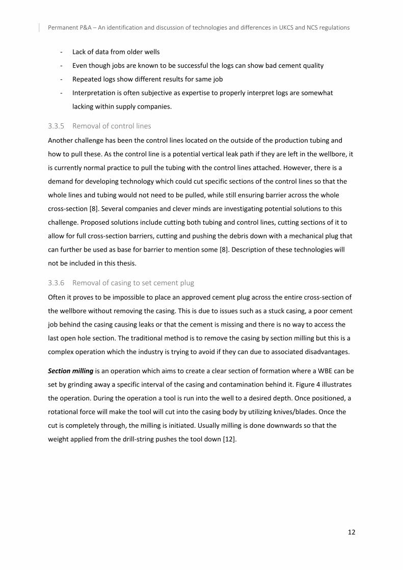
Section milling is an operation which aims to create a clear section of formation where a WBE can be
set by grinding away a specific interval of the casing and contamination behind it. Figure 4 illustrates
the operation. During the operation a tool is run into the well to a desired depth. Once positioned, a
rotational force will make the tool will cut into the casing body by utilizing knives/blades. Once the
cut is completely through, the milling is initiated. Usually milling is done downwards so that the
weight applied from the drill-string pushes the tool down [12].

Permanent P&A – An identification and discussion of technologies and differences in UKCS and NCS regulations
13
Figure 4: Section Milling operation [13]
As mentioned one does not wish to perform section milling if it can be avoided. This is due to reasons
such as [14]:
1. It is time consuming which will lead to high cost.
2. It generates swarf. Swarf is the cuttings/metal shavings that accompanies the milling
operation. Swarf is difficult to handle and can potentially cause serious problems downhole
in addition to harming equipment such as the BOP when circulated out. To avoid well
integrity issues because of a failed BOP, it has to be dismantled, inspected and repaired at
considerable expenses after milling operations.
3. The operation causes excessive vibrations that could harm equipment in the bottom hole
assembly (BHA).
4. HSE challenges are created due to the swarf and debris handling and disposal. The metal
returns have sharp surfaces which means that personal protective equipment must be worn
to avoid damages to eyes and hands. Environmental issues arise from the point of collection
on the rig to the final disposal site. Issues include material documentation and classification,
handling, containment, tracking and transport.
Due to the negative implications associated with section milling several new technologies has been
developed in recent years which eliminates the need to perform section milling in P&A activities. The
alternatives are described in section 0.
3.3.7 Cooperation within market
P&A has been a somewhat neglected part of offshore oil and gas operations in terms of coming up
with new, and more cost-effective solutions for several years. But as the field has been given more
attention from the public and authorities in terms of requirements, and with the increasing number

Permanent P&A – An identification and discussion of technologies and differences in UKCS and NCS regulations
14
of wells in need of P&A, the industry has realized that attention to the field is long overdue. Based on
this several efforts have been made to develop new technologies and increase the sharing of
knowledge across company, and country, borders. Some examples are the initiative to start yearly
P&A seminars where challenges and recent development can be presented and discussed, and Joint
Industry Projects (JIP) to both develop and test new technologies on pilot wells. These initiatives for
sharing of knowledge is a key to overcoming the challenges related to P&A.
3.3.8 Temporarily abandoned wells
Previously there has not been any regulations for how long a well can be temporarily abandoned. In
the newest revision of the NORSOK D-010 this has changed and temporary abandonment is defined
as with or without monitoring. If a well is temporarily abandoned with monitoring, there is no
maximum abandonment period. If a well is temporarily abandoned without monitoring however,
there is a maximum period of three years. The lack of regulations in the past has led to a number of
wells being temporarily abandoned, even though they are not planned to be re-used, because there
is no value creation with P&A. It has been easy to postpone permanent P&A operations and focus
more on value creating areas like drilling.
Now that the regulation for temporarily abandonment has changed, it means that there are several
wells which has been temporarily abandoned for a long time that are now in need of permanent
abandonment within a relatively short period of time. To avoid situations like this in the future there
are some measures identified by the PSA that operator should take such as [15]:
- New wells (exploration wells) should be permanently P&A as soon as finished if they are not
planned to be re-used in the future
- Temporary P&A should be temporary and not be a long-run solution for wells
- Wells that are temporarily abandoned should be evaluated on a regular basis where the
integrity status and potential plans for future use should be evaluated.
3.3.9 Regulations and requirements
Different countries, and parts of countries, has different governmental requirements and regulations
that the operators need to deal with when performing P&A, in addition to company specific
requirements. This means that operators, and their associations, may need to alter their methods for
performing P&A based on where in the world the well is located.
Permanent P&A – An identification and discussion of technologies and differences in UKCS and NCS regulations
15
In addition, the current regulations/standards might be a challenge for the new technologies that are
being developed. The new technologies/methods may not fit entirely within the scope of/be covered
by the current standards and regulations. As a result, the companies cannot apply the requirements
directly even though methods have been proven to work in a safe manner through pilot-wells and
other testing. This means that the system need to go through a qualification process before it can be
implemented on a live subsea well to perform well intervention or P&A.
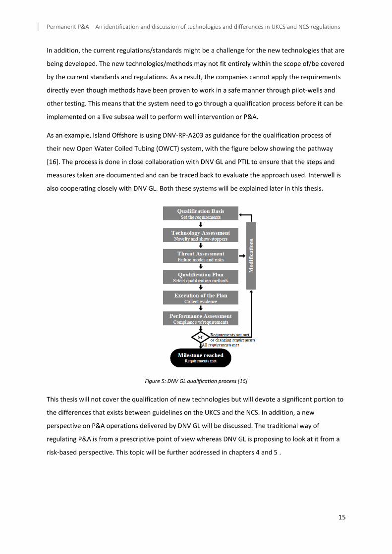
As an example, Island Offshore is using DNV-RP-A203 as guidance for the qualification process of
their new Open Water Coiled Tubing (OWCT) system, with the figure below showing the pathway
[16]. The process is done in close collaboration with DNV GL and PTIL to ensure that the steps and
measures taken are documented and can be traced back to evaluate the approach used. Interwell is
also cooperating closely with DNV GL. Both these systems will be explained later in this thesis.
Figure 5: DNV GL qualification process [16]
This thesis will not cover the qualification of new technologies but will devote a significant portion to
the differences that exists between guidelines on the UKCS and the NCS. In addition, a new
perspective on P&A operations delivered by DNV GL will be discussed. The traditional way of
regulating P&A is from a prescriptive point of view whereas DNV GL is proposing to look at it from a
risk-based perspective. This topic will be further addressed in chapters 4 and 5 .
Permanent P&A – An identification and discussion of technologies and differences in UKCS and NCS regulations
16
3.4 New technology
As mentioned there has been an increased focus on P&A operations in recent years as the demand
have become more evident. The development has focused on challenges like eliminating the need
for rigs and section milling in addition to introducing alternative plugging materials. This section will
present some of the new technologies that has emerged, with some of them already being proven
while others are still in the design/qualification/testing phase.
3.4.1 Perforate, wash and cement to establish well barrier
Perforate, wash and cement (PWC) is a technology which eliminates the need for section milling in
P&A operations. The operational sequence, given in the name, is to perforate the casing rather than
to mill it, to wash away cement and/or formation behind it and then to set a cement plug. The
operation is performed by drill-pipe or coiled tubing [14]. The method eliminates swarf generation
and the casing will be left primarily intact, allowing for a re-entry on a later occasion. The production
tubing is cut and pulled, and if there are more than two casings they also have to be removed before
the PWC operation can commence.
In this thesis, the PWC system developed by HydraWell will be used to describe the general system
and the savings it provides as this system has been accepted and proven in the industry.
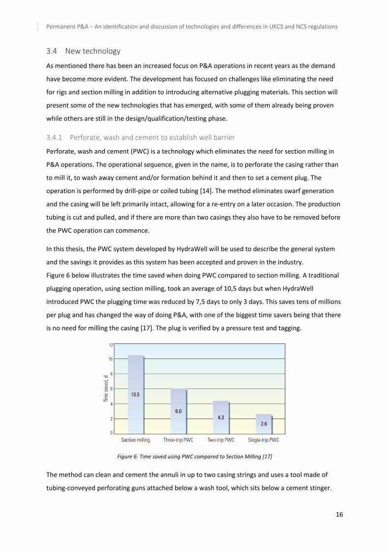
Figure 6 below illustrates the time saved when doing PWC compared to section milling. A traditional
plugging operation, using section milling, took an average of 10,5 days but when HydraWell
introduced PWC the plugging time was reduced by 7,5 days to only 3 days. This saves tens of millions
per plug and has changed the way of doing P&A, with one of the biggest time savers being that there
is no need for milling the casing [17]. The plug is verified by a pressure test and tagging.
Figure 6: Time saved using PWC compared to Section Milling [17]
The method can clean and cement the annuli in up to two casing strings and uses a tool made of
tubing-conveyed perforating guns attached below a wash tool, which sits below a cement stinger.

Permanent P&A – An identification and discussion of technologies and differences in UKCS and NCS regulations
17
The tool is run to plug-setting depth and then the guns are fired to perforate the casing. The guns
have a disconnect function which drops it after firing. Now, the wash tool is located at the bottom of
the BHA. This tool has bypass channels for running in and elastomer cups to direct the flow during
washing. Above the wash tool a cement stinger is placed for cementing the section after it is cleaned
[13].
The wash tool is used to wash and clean out debris, old mud, barite, old cuttings and cement traces
in the annulus behind the casing. The washing is illustrated in Figure 7, with mud flowing from the
bottom elastomer cup to clean the annulus and return the debris to surface.
Once washing is complete the tool is moved to the bottom of the perforations and a cement spacer
is pumped into the annular space as the tool is pulled upwards. The wash tool is then disconnected
from the cement stinger, and the wash tool is pushed to the bottom of perforations and will serve as
base for the cementing operation. The wash tool is designed to maintain contact with the casing
inner wall.
Figure 7: The HydraWash tool [18]
Following this, the interval is cemented through the stinger. The cement is squeezed into the
perforations. Unlike section milling, this system provides a plug that can be verified in the annulus. If
this is needed, the plug is drilled out after it has set and a log is run to verify the bond in the annulus.
After, a new cement plug has to be placed inside the casing with a new verification according to
regulators requirements [13].
HydraWell states that they have run 1 of 200 plugs on CT, the other has been run on drill-string. The
challenges with running on CT are [19]:
- Pump rate – creating the necessary lift in well to get the washings out of well
- Rotation during washing. Currently a hydraulic rung indexing tool which rotates the BHA 30
degrees is being used

Permanent P&A – An identification and discussion of technologies and differences in UKCS and NCS regulations
18
- Rotation during cementing. HydraWell is working on developing a hydraulic down-hole
engine which can rotate the BHA during cementing
- From boat, with or without riser, it must be ensured that the washings from behind the
casing is lifted from the well to the boats mud system.
As outlined, the benefits of using a PWC operation over section milling are many. PWC allows for the
verification of annulus cement and possibility for re-entry to the well, it provides a safer working
environment for the operating personnel and it limits the exposure of swarf and metal associated
with milling. It also reduces the need for additional surface handling equipment due to the milling
debris, the need for BOP inspection and meets all regulatory requirements. And, it has been proven
that significant time and money are saved by using the PWC technique over section milling [17].
Comment: Another potential benefit (to both systems) is if PWC can be incorporated in a rig-less
coiled tubing system. This will however be limited by lubricator and toolstring length and the ability
to cut if needed in addition to the CT challenges listed above. If using CT, the TCP guns are installed in
multiple runs. More on rig-less coiled tubing will follow in section 3.4.5.
3.4.2 Alternatives to cement as barrier
Cement is traditionally used for barrier material but it is not necessarily the best option in terms of
properties. Especially as cement is a material which can crack and create leak paths in case of
changing pressures and temperature. Alternatives has been investigated and in some cases
implemented in recent years. This section will give a presentation of some alternatives to cement as
barrier material.
3.4.2.1 Use formation as barrier
A phenomenon which has been noticed and taken advantage of in recent years is that formation can
be used as part of external barrier. It was discovered after several bond logs showed solid material
behind the casing far above the expected top of cement. In most cases it has been good correlations
between shale/clay zones and zones showing bonding which indicates that the shale has sealed off
the annular region and that it is the presence of such formation material that resulted in a good bond
log response [8]. The formation can be used as part of well barrier if there is a sufficient amount of
formation packed on the outside of casing. On a seminar in 2012, Statoil stated to have used this
method on more than 100 wells with an 15 MNOK average cost reduction per well [20]. The
approach can replace critical operations like section milling and casing pulling but there is a challenge
to find logs which can accurately prove and verify the formation as barrier. Also, the presence of

Permanent P&A – An identification and discussion of technologies and differences in UKCS and NCS regulations
19
bonded shale cannot be predicted and due to this it shall always be planned for using cement as back
up even though formation as barrier is the preferred solution.
3.4.2.2 Sandaband and ThermaSet
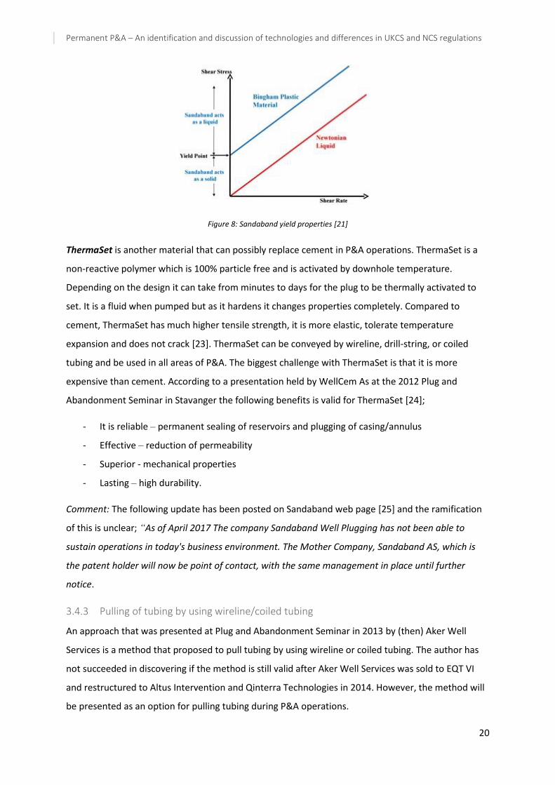
Sandaband is a sand-slurry which contains a wide variety of particle sizes. The volume of Sandaband
is roughly 30% liquid and 70% solid where the liquid is coating the solids particles, and the solids
move relatively to each other after the material is in place, and no segregation will occur. The
material has Bingham-plastic properties which means that it will act as a fluid when shear stresses
exceed the yield stress, this is illustrated in Figure 8. As illustrated the material acts as a sold below
the yield point and as a liquid above it. This will cause the material to reshape instead of fracture
once subjected to shear stresses above yield point [21].
The material is pumped as a liquid but sets as a solid mass once in place. Because Sandaband is non-
reactive, gas tight, not able to fracture and there is no volume shrinking the material avoids well
integrity issues. Also, the verification of the plug can start immediately after the total volume has
been displaced. This has the potential to save lot of time compared to cement which has to wait for
the slurry to set. Verification is performed by mud circulation above and below the expected top of
slurry while observing the return over the shakers.
Sandaband is mainly made of quartz and water, making it HSE friendly and it remains unaffected by
downhole fluids due to quartz being a thermodynamic stable material. A challenge with Sandaband is
that it cannot be set on top of a fluid and thus need a foundation [22].
To summarize, the benefits of using Sandaband in P&A include;
₋ No need for milling which saves time.
₋ It is easier to place than cement which save time.
₋ Does not set up prematurely, meaning less risk is involved.
₋ There are no losses to formation.
₋ Non-hazardous and environmentally friendly.
₋ Ductile and adaptable, no fracture, no leaks.
₋ No issue with downhole fluid contamination.
₋ Robust and non-complex, it relies purely on physical properties.
Permanent P&A – An identification and discussion of technologies and differences in UKCS and NCS regulations
20
Figure 8: Sandaband yield properties [21]
ThermaSet is another material that can possibly replace cement in P&A operations. ThermaSet is a
non-reactive polymer which is 100% particle free and is activated by downhole temperature.
Depending on the design it can take from minutes to days for the plug to be thermally activated to
set. It is a fluid when pumped but as it hardens it changes properties completely. Compared to
cement, ThermaSet has much higher tensile strength, it is more elastic, tolerate temperature
expansion and does not crack [23]. ThermaSet can be conveyed by wireline, drill-string, or coiled
tubing and be used in all areas of P&A. The biggest challenge with ThermaSet is that it is more
expensive than cement. According to a presentation held by WellCem As at the 2012 Plug and
Abandonment Seminar in Stavanger the following benefits is valid for ThermaSet [24];
- It is reliable – permanent sealing of reservoirs and plugging of casing/annulus
- Effective – reduction of permeability
- Superior - mechanical properties
- Lasting – high durability.
Comment: The following update has been posted on Sandaband web page [25] and the ramification
of this is unclear; “As of April 2017 The company Sandaband Well Plugging has not been able to
sustain operations in today's business environment. The Mother Company, Sandaband AS, which is
the patent holder will now be point of contact, with the same management in place until further
notice.
3.4.3 Pulling of tubing by using wireline/coiled tubing
An approach that was presented at Plug and Abandonment Seminar in 2013 by (then) Aker Well
Services is a method that proposed to pull tubing by using wireline or coiled tubing. The author has
not succeeded in discovering if the method is still valid after Aker Well Services was sold to EQT VI
and restructured to Altus Intervention and Qinterra Technologies in 2014. However, the method will
be presented as an option for pulling tubing during P&A operations.

Permanent P&A – An identification and discussion of technologies and differences in UKCS and NCS regulations
21
The method presented eliminates the need for using a drilling rig or other heavy equipment. The
system presented need a pipe handling system for when tubing come to surface in addition to
general wireline equipment. The essence of the method is to inject gas to displace heavier fluid and
generate buoyancy effect which will aid in pulling the tubing [26].
The method has the following operational sequence:
1) The tubing is cut right below the tubing hanger and the tubing hanger is removed.
2) A plug with check valve functionality is installed at the bottom of the cut tubing.
3) A tubing pulling tool is engaged at the top of the tubing. This has a control module and a
seal and anchor module which seals of the relevant tubing interval.
4) Gas is injected through the system and into the tubing section. This displaces the heavier
fluid inside to generate additional buoyancy force.
5) The tubing is pulled to surface.
3.4.4 Interwell rig-less P&A
Another advancement within the field of P&A is Interwell ongoing development of a rig-less
approach which does not require removal of tubing prior to P&A operation and has no need for drill
pipe when placing primary/secondary barriers. The solution is designed and optimized to be
conveyed on E-line, wireline or coiled tubing. This unconventional technology aims to restore a
reservoir barrier with properties similar to the original cap-rock by essentially melting the in-situ
material such as metal, cement and in part formation in an exothermic process. The goal is that this
will provide a barrier which is solid in an eternal perspective. The general idea is based on natural
magma processes occurring in the earth and trying to copy what happens when magma moves
around in the inner channels of the earth before becoming solid rock [27].
The technology is in the development phase and at the time-being Interwell is using pilot wells for
testing the system. The testing is being done in close collaboration with DNV GL and regulatory
agencies. According to commercial manager at Interwell they are planning to perform approximately
15 pilot wells onshore and the first offshore pilot well on a North Sea platform by end of 2017 or
start of 2018. The biggest challenge identified by Interwell is for the technology to fit within the
framework of regulations and getting sufficient track record and documentation in place [28].
The following description of the technology is extracted from patent WO 2013135583 A2 which is the
only publicly available written material on the technology.
The method can be used for permanent well abandonment or removal of a well element arranged in
a well by use of a thermite mixture and consist of the following steps [29]:

Permanent P&A – An identification and discussion of technologies and differences in UKCS and NCS regulations
22
- Provide a sufficient amount of heat generating mixture where the amount is customized
according to desired operation
- Position the heat generating mixture at the desire depth in the well
- Ignite the mixture and thereby melting the surrounding materials in the well.
- When mixture has burnt out, the melted materials will solidify and form a plug against the
formation, comprising of the melted materials.
The method may comprise of positioning a minimum of one high temperature resistant element
close to the melting area to protect parts of the well which lie above, below and/or contiguous to the
melting position. For P&A operations it may also be placed a permanent plug (e.g. bridge plug) in the
well with a high temperature resistance plug above/below it to aid in positioning and protect the rest
of the wellbore.
For igniting the heat generating mixture, a timer may be used in connection with the igniting head.
Such a function might be useful when several wells in close proximity to each other are being
abandoned, e.g. from same template, and the timer in each well can then be set to ignite at the same
time, or different times, after the vessel has left location. This will reduce safety risk to personnel.
Comment: The patent states that as the plug created will have other properties than the cement
usually used in abandonment, the NORSOK standard requirements may not be relevant for all
applications and operations. This is an interesting point and should be seen in relation to the
challenges that exist with current regulations and discussion that will follow in this thesis.
3.4.5 Open Water Coiled Tubing
Open water coiled tubing (OWCT) is an approach to P&A and well intervention which has been
investigated in recent years but is yet to be utilized on a live well. As the name suggest OWCT is when
the CT is run through open water without being protected by a riser. This means that the CT itself is
acting as a riser and it is now subjected to environmental loads, and it is a barrier between the well
and its surroundings.
Island Offshore Subsea (IOSS) is the company who is believed to have developed the OWCT
technology the furthest. IOSS has proven that OWCT can be performed successfully from a monohull
vessel through the Rogfast project and a pilot hole drilling for Centrica [30]. For the Rogfast project
IOSS drilled core samples using OWCT and for Centrica they drilled a pilot hole to check for shallow
gas. The technology had never been utilized in the offshore petroleum-industry before and proved to
be a safer and cheaper alternative to traditional drilling. Centrica estimated that they saved about 30
- 50% by using this riser-less method on the Butch field project. These projects did however not
require any well integrity control.

Permanent P&A – An identification and discussion of technologies and differences in UKCS and NCS regulations
23
If OWCT can be proven successfully on live wells it could be beneficial to utilize the technology for
both well intervention and P&A operations, which could make OWCT a preferred solution [31].
For the system being developed by IOSS they believe it can be utilised in the applications presented
in Table 1 below.
Table 1: Applications for open water coiled tubing
RLWI services
Scale and sand cleanout
Stimulation, circulation, fracturing and acidizing
Cement squeeze
Plug and abandonment
Circulation and cleaning
Cementing
Milling
CT drilling
Drilling and coring
Pilot hole drilling
Side track and drilling in shallow reservoirs
The basic topsides elements of a CT system are more or less the same whether it’s a conventional
platform system with dry tree or an OWCT with subsea tree. But, for the OWCT system the pressure
control components are moved subsea and placed on top of the XT and wellhead at seabed in
contrast to a conventional system which has all the necessary equipment at surface since the
wellhead and XT is placed at surface. A basic illustration of this is showed in Figure 9 below.
Figure 9: Conventional versus open water coiled tubing [32]

Permanent P&A – An identification and discussion of technologies and differences in UKCS and NCS regulations
24
If the OWCT system can be qualified and implemented it can be used to install and place the cement
barriers in the annulus or establish a cement plug inside casing when cement behind the casings is
verified. By using riserless CT less contamination of the cement will be expected to occur and hence
one can obtain improved quality of the cement plug. During the 2016 Plug and Abandonment
Seminar, Island Offshore gave a presentation where they outlined the challenges for P&A on subsea
completed wells from LWI vessel to be as shown in Figure 10 [33]. In addition to the challenges
shown in the figure Island Offshore also pointed out that the methodologies should be challenged,
specifically why things are different in the UKCS and the NCS. Some of these challenges has been
addressed previously and they will not be further elaborated on in this section although they might
need to be solved differently for the OWCT system than for other methods.
Figure 10: Challenges for doing P&A from LWI vessels on subsea wells [33]
Permanent P&A – An identification and discussion of technologies and differences in UKCS and NCS regulations
25
4 Requirements and Regulations
This chapter will give a presentation of the current guidelines and standards being utilized on NCS
and UKCS. In addition, a new risk-based perspective being suggested by DNV GL will be presented.
For the NCS the governing standard is the NORSOK D-010 rev 4, Well integrity in drilling and well
operations. On the UKCS the guideline Guidelines for the abandonment of wells, issue 5 is used. In
2016 DNV GL published a recommended practice, DNVGL-RP-E103 Risk-based abandonment of
offshore wells which also will be described in this chapter. Further, the three will be discussed and
compared in chapter 5, aiming to propose changes that could be made to the NORSOK D-010 to
increase cost-effectiveness of P&A.
4.1 NORSOK D-010 – Well integrity in drilling and well operations
“The NORSOK standards are developed by the Norwegian petroleum industry as a part of the
NORSOK initiative and supported by the Norwegian Oil and Gas Association and the Federation of
Norwegian Industries. NORSOK standards are administered and issued by Standards Norway. The
purpose of NORSOK standards is to contribute to meet the NORSOK goals, e.g. by replacing individual
oil company specifications and other industry guidelines and documents for use in existing and future
petroleum industry developments.” [6].
NORSOK D-010 focus on well integrity by defining the minimum functional and performance
requirements and guidelines for well design, planning and execution of well activities. The standard
focus on establishing well barriers and also covers well integrity management and personnel
competence requirements.
The standard is divided into four main scenarios for abandonment activities [6]:
- Suspension of well activities and operations
- Temporary abandonment of wells
- Permanent abandonment of wells
- Permanent abandonment of a section in a well (side-track, slot recovery) to construct a new
wellbore with a new geological well target
This thesis will concentrate on the permanent abandonment of wells. However, it is worth
mentioning that the standard separates between temporary abandonment with and without
monitoring where it states that if there is no monitoring the maximum abandonment period is three
Permanent P&A – An identification and discussion of technologies and differences in UKCS and NCS regulations
26
years. If monitoring exists there is no maximum abandonment period. This provides an additional
incentive to develop better solutions for permanent abandonment.
4.1.1 Definitions
The following definitions are taken from NORSOK D-010 [6].
Cement – collective term for cement and non-cementitious materials that is used to replace cement
Permanent abandonment – well status where the well is abandoned permanently and will not be
used or re-entered again
Permanent well barrier – a well barrier which permanently seals a source of inflow
Reservoir – a formation which contains free gas, movable hydrocarbons, or abnormally pressured
movable water
Source of inflow – same definition as reservoir
Shall – a strict requirement that are to be followed and no deviation is allowed unless accepted by all
involved parties
Should – indicates that among several possibilities one is recommended without mentioning or
excluding others, or that a certain course of action is preferred but not required
4.1.2 Abandonment design
The NORSOK D-010 states that all sources of inflow shall be identified and documented and all WBE
used for plugging of wells shall withstand the load and environmental conditions the may be exposed
to for the abandonment period. For permanently abandoned wells the period is eternity.
The design basis should include the following:
a) Well configuration including depths and specification of formations, casing strings, casing
cement, wellbores and side-tracks.
b) Stratigraphic sequence of each wellbore showing reservoir and information about current
and future production potential
c) Logs, data and information from cementing jobs
d) Formations with suitable WBE properties
e) Specific well conditions such as scale build up, casing wear, H2S, CO2 etc.
Further the standard gives guidelines for which uncertainties should be accounted for in relation to
WBE, different load cases to design for, design factors for temporary abandonment and well control
procedures, actions and requirements.

Permanent P&A – An identification and discussion of technologies and differences in UKCS and NCS regulations
27
Cutting/perforating the casing and retrieving seal assemblies shall be performed with active pressure
control equipment in place to prevent uncontrolled flow.
4.1.3 Well barrier
A permanently abandoned well shall be plugged with an eternal perspective. When plugging one
shall take the effects of any foreseeable chemical and geological processes into account and the
eternal perspective with regards to re-charge of formation pressure shall be verified and
documented. The number of well barriers depends on the source of inflow. NORSOK D-010 states
that one well barrier is sufficient for the following situations of inflow;
- Undesirable cross flow between formation zones
- Normally pressured formation with no hydrocarbon and no potential to flow to surface
- Abnormally pressured hydrocarbon formation with no potential to flow to surface
Two well barriers shall be in place when there is;
- Hydrocarbon bearing formations
- Abnormally pressured formation with potential to flow to surface
Table 2 below, copied from NORSOK D-010, states the individual or combined well barriers which
shall be installed during P&A [6]. Multiple reservoirs/perforations located within the same pressure
regime can be regarded as one reservoir for which a primary and secondary well barrier shall be
installed. A well barrier can function as a shared well barrier for more than one wellbore.
Table 2: Well Barriers depth position
Name Function Depth position
Primary well barrier To isolate a source of inflow, formation with normal pressure or over-pressured/impermeable formation from surface/ seabed
The base of the well barriers shall be positioned at a depth were formation integrity is higher than potential pressure below
Secondary well barrier Back-up to the primary well barrier, against a source of inflow
As above
Crossflow well barrier To prevent flow between formations (where crossflow is not acceptable). May also function as primary well barrier for the reservoir below.
As above

Permanent P&A – An identification and discussion of technologies and differences in UKCS and NCS regulations
28
Open hole to surface barrier To permanently isolate flow conduits from exposed formation(s) to surface after casing(s) are cut and retrieved and contain environmentally harmful fluids. The exposed formation can be over-pressured with no source of inflow. No hydrocarbons present.
No depth requirement with respect to formation integrity
Permanent well barriers shall extend across the full cross section of a well, include all annuli and seal
in both horizontal and vertical direction as shown in Figure 11. The well barrier shall be placed
adjacent to an impermeable formation with sufficient formation integrity to withstand the maximum
expected pressure. Control lines and cables shall not be part of the permanent well barrier, hence
these and other downhole equipment must be removed when they can cause loss of well integrity
[6].
Figure 11: Illustration of cross-sectional requirement for permanent well barriers [6]
4.1.3.1 Material
NORSOK D-010 does not state which material to use, but cement is most common. The standard
states that the suitability of plugging material shall be verified and documented. Any degradation of
the casing should be considered. The standard states that a permanent well barrier should have the
following characteristics:
a) provide long term integrity (eternal perspective)
b) impermeable
c) non-shrinking
d) able to withstand mechanical loads/impact
e) resistant to chemicals/ substances (H2S, CO2 and hydrocarbons)
f) ensure bonding to steel
g) not harmful to the steel tubulars integrity

Permanent P&A – An identification and discussion of technologies and differences in UKCS and NCS regulations
29
4.1.3.2 Casing cement in primary and secondary well barriers
The same casing cement can become WBEs in both the primary and secondary well barrier if the
acceptance criteria for casing cement (EAC 22) are fulfilled. The EAC requires 2 x 30m measured
depth (MD) intervals of bonded cement which shall be obtained by logs and verified by qualified
personnel. The casing cement is not defined as a common WBE.
Common WBE can be accepted in some cases when it is not possible to establish two independent
well barriers but should be avoided if feasible. A risk analysis shall be performed and risk reducing
measures applied when a common WBE exists.
4.1.4 Well barrier element
Well barrier elements are physical elements which in themselves does not prevent flow but in
combination with other WBE’s form a well barrier. To clarify, the previously mentioned well barrier is
an envelope of one or several WBE preventing fluids from flowing unintentionally from the formation
into the wellbore, into another formation or to the surrounding environment [6]. Both well barrier
and WBE shall be designed so that a single failure of a well barrier or WBE cannot lead to an
uncontrolled flow of wellbore fluids/gases to the external environment.
NORSOK D-010 includes a specific chapter, 15, devoted to Well barrier element acceptance criteria
(EAC). This section contains 59 tables including criteria for cement plug, casing cement, in-situ
formation and material plug amongst others. Each table contains information as shown in Table 3. In
addition to the EAC in section 15, there are some additional requirements and guidelines for WBE in
a permanently abandoned well which will be presented in the following sub-sections.
Table 3: Content of well barrier element acceptance criteria tables [6]
Features Acceptance Criteria See
A. Description Description of the WBE
B. Function Describes the main function of the WBE
C. Design (capacity, rating and function), construction and selection
For WBEs that are constructed in the field (e.g. drilling fluid, cement), this should describe
a) design criteria, such as maximal load conditions that the WBE shall withstand and other functional requirements for the period that the WBE will be used,
b) construction requirements for the WBE or its sub-components, and will in most cases consist of references to normative standards.
For WBEs that are pre-manufactured (production packer, DHSV), the focus should be on selection parameters for choosing the right equipment and proper field installation
Name of specific references
D. Initial test and verification
Describes the methodology for verifying the WBE being ready for use and being accepted as part of a well barrier
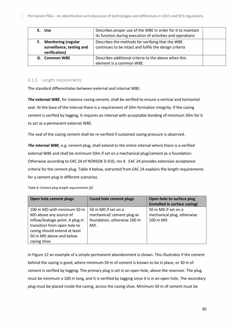
Permanent P&A – An identification and discussion of technologies and differences in UKCS and NCS regulations
30
E. Use Describes proper use of the WBE in order for it to maintain its function during execution of activities and operations
F. Monitoring (regular surveillance, testing and verification)
Describes the methods for verifying that the WBE continues to be intact and fulfils the design criteria
G. Common WBE Describes additional criteria to the above when this element is a common WBE
4.1.5 Length requirements
The standard differentiates between external and internal WBE.
The external WBE, for instance casing cement, shall be verified to ensure a vertical and horizontal
seal. At the base of the interval there is a requirement of 50m formation integrity. If the casing
cement is verified by logging, it requires an interval with acceptable bonding of minimum 30m for it
to act as a permanent external WBE.
The seal of the casing cement shall be re-verified if sustained casing pressure is observed.
The internal WBE, e.g. cement plug, shall extend to the entire interval where there is a verified
external WBE and shall be minimum 50m if set on a mechanical plug/cement as a foundation.
Otherwise according to EAC 24 of NORSOK D-010, rev 4. EAC 24 provides extensive acceptance
criteria for the cement plug. Table 4 below, extracted from EAC 24 explains the length requirements
for a cement plug in different scenarios.
Table 4: Cement plug length requirements [6]
Open hole cement plugs Cased hole cement plugs Open hole to surface plug (installed in surface casing)
100 m MD with minimum 50 m MD above any source of inflow/leakage point. A plug in transition from open hole to casing should extend at least 50 m MD above and below casing shoe.
50 m MD if set on a mechanical/ cement plug as foundation, otherwise 100 m MD.
50 m MD if set on a mechanical plug, otherwise 100 m MD
In Figure 12 an example of a simple permanent abandonment is shown. This illustrates if the cement
behind the casing is good, where minimum 50 m of cement is known to be in place, or 30 m of
cement is verified by logging. The primary plug is set in an open hole, above the reservoir. The plug
must be minimum a 100 m long, and it is verified by tagging since it is in an open hole. The secondary
plug must be placed inside the casing, across the casing shoe. Minimum 50 m of cement must be
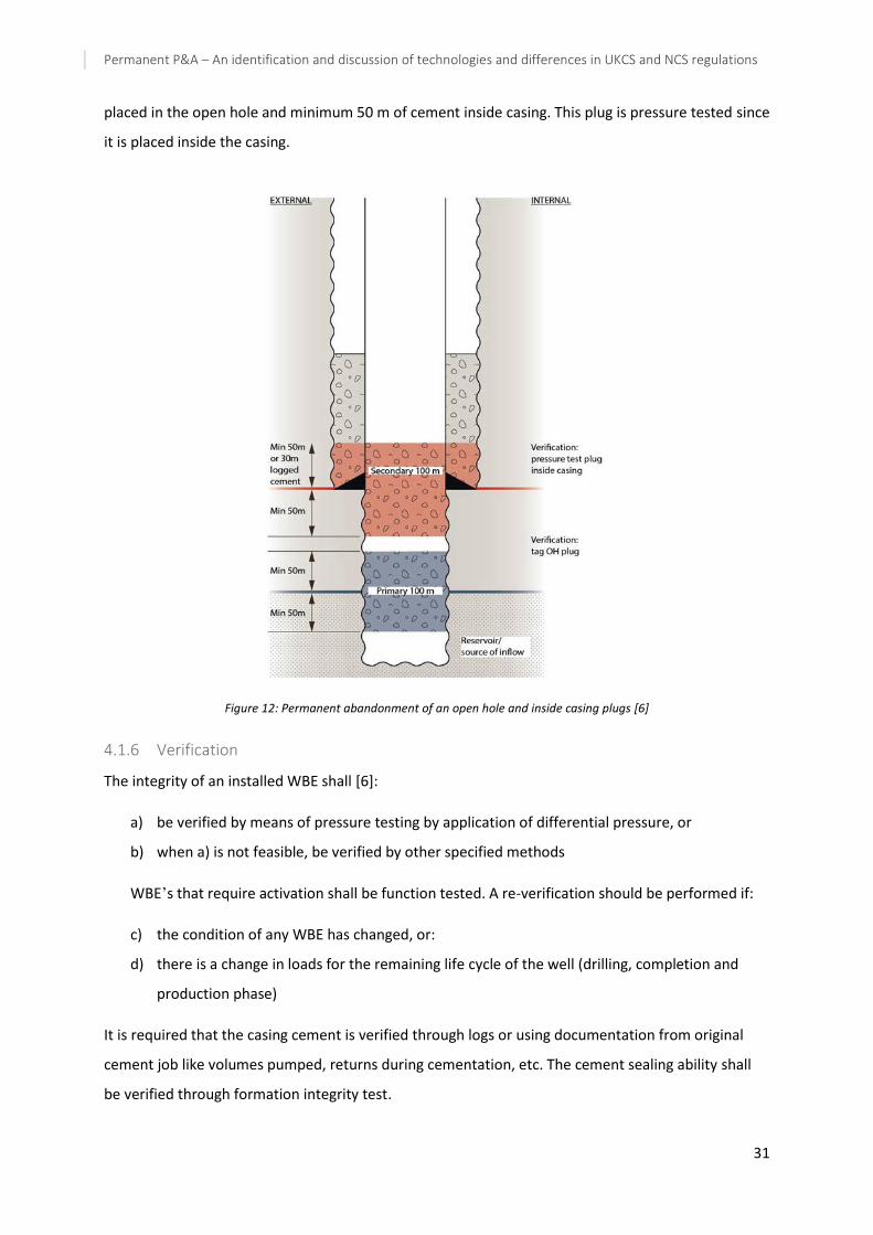
Permanent P&A – An identification and discussion of technologies and differences in UKCS and NCS regulations
31
placed in the open hole and minimum 50 m of cement inside casing. This plug is pressure tested since
it is placed inside the casing.
Figure 12: Permanent abandonment of an open hole and inside casing plugs [6]
4.1.6 Verification
The integrity of an installed WBE shall [6]:
a) be verified by means of pressure testing by application of differential pressure, or
b) when a) is not feasible, be verified by other specified methods
WBE’s that require activation shall be function tested. A re-verification should be performed if:
c) the condition of any WBE has changed, or:
d) there is a change in loads for the remaining life cycle of the well (drilling, completion and
production phase)
It is required that the casing cement is verified through logs or using documentation from original
cement job like volumes pumped, returns during cementation, etc. The cement sealing ability shall
be verified through formation integrity test.

Permanent P&A – An identification and discussion of technologies and differences in UKCS and NCS regulations
32
4.1.7 Removing equipment above seabed
For permanently abandoned wells there should be no equipment left at the seabed, nor should any
be revealed in the future. Because of this, the wellhead and casings shall be removed below the
seabed at a depth which ensures no stick-up in the future [6]. The required cutting depth shall be
such that there is no conflict with other marine activities, and one must consider local conditions
such as soil and seabed scouring due to sea current when deciding on the cutting depth. In deep
water wells it may be acceptable to leave or cover the wellhead. The preferred method for removal
of casing/conductor is to use mechanical or abrasive cutting, however the use of explosive is
acceptable if the risk to the surroundings is at the same level as conventional cutting
4.1.8 Well barrier schematics
Well barrier schematics (WBS) are practical illustrations of the well showing the different barriers and
where they are located. WBS shall be prepared for every well activity and operation, and a final
verified WBS shall be in place for the well status upon completing operations. The WBS should
contain information such as [6];
- Drawing of barriers and where they are located
- Formation integrity when it is part of the barrier
- Potential sources of inflow
- Listing of WBEs with requirement for verification
- All casing and cement
- Well information such as field, type, name, status etc.
- Any WBE failures
- Important well integrity information
The following examples of WBSs, shown in Figure 13 and Figure 14 are copied from the standard and
they represent one possible solution for defining and illustrating the well barriers with WBE [6].
- The primary well barrier is shown in its normal working stage, where the WBEs are exposed
to the wellbore pressure. This is shown in blue.
- The secondary well barrier is shown in its ultimate stage, where a WBE (e.g. shear/seal
ram/valve) is activated to close the well barrier envelope. This is shown in red.
- An open hole to surface barrier shown in green.
On the side of the illustrations in the standards there is a written statement of which elements are
included in the well barriers with reference to the well barrier elements acceptance tables.
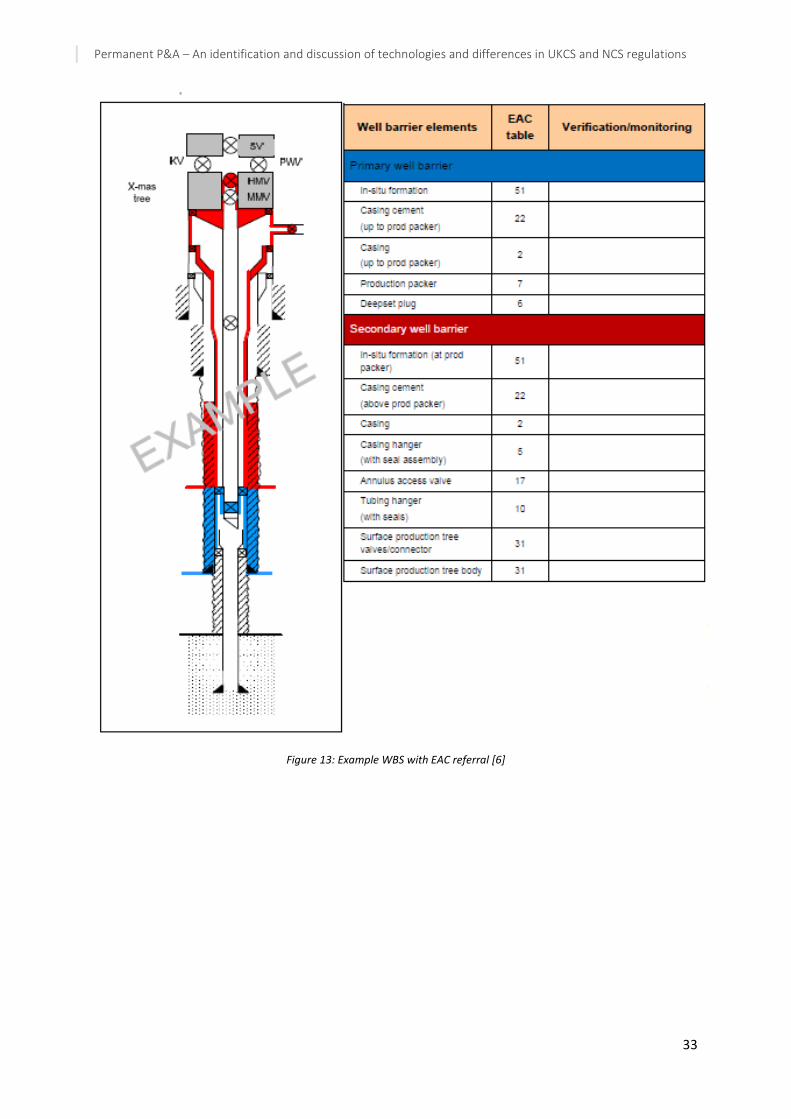
Permanent P&A – An identification and discussion of technologies and differences in UKCS and NCS regulations
33
Figure 13: Example WBS with EAC referral [6]

Permanent P&A – An identification and discussion of technologies and differences in UKCS and NCS regulations
34
Figure 14: Example of WBSs [6]
Explanations to Figure 14:
(A) Illustrates a WBS for the scenario of an open hole P&A
(B) Illustrates the situation for an open hole P&A with casing used when there is no source of
inflow.
(C) Illustrates a perforated well with tubing left in hole.
(D) Illustrates a perforated well with tubing removed.
(E) Illustrates a multi bore well with slotted liners or sand screens. The orange plug illustrates a
cross flow barrier.
(F) Illustrates a well with slotted liner in multiple reservoirs
4.1.9 Examples of different options for setting the plug
When abandoning a well there are several options for where in the wellbore to set the plugs. Some
possibilities are that one can set an open hole cement plug across the reservoir, back-to-back cement
plugs from the reservoir or combine cement plug with a mechanical plug as foundation above the
reservoir. These different options are illustrated through 1-4 in Figure 15 and explained below.

Permanent P&A – An identification and discussion of technologies and differences in UKCS and NCS regulations
35
Figure 15: Examples of different options for setting plugs for permanent abandonment [6]
(1) – An open hole cement plug across/above the reservoir is set to abandon the last open hole
section of a wellbore. An additional cement plug is set from the open hole into the casing.
Requirement is to have sufficient formation integrity at the base of both well barriers.
(2) – Two back-to-back cement plugs from the reservoir (or as close as possible to the reservoir)
is set du abandon the last open hole section of a wellbore or a perforated casing/liner. This is
an option provided the cement in the annulus is verified. The internal cement plug length
covers the logged interval in the annulus.
(3) – A mechanical plug serves as foundation for a single cement plug to abandon a wellbore.
The internal cement plug length covert the logged interval in the annulus.
(4) – The last section of a perforated casing/liner or wellbore is abandoned by setting a primary
cement plug above the reservoir (or as close to the reservoir as possible) and the secondary
cement plug is set within the tubing and tubing annulus.
4.1.10 Methods to establish cement plug
The standard illustrates roadmaps to establish a permanent well barrier for wells with poor casing
cement or no access to the last open hole section in order to establish contact between plug and
formation. The alternatives shown in NORSOK D-010 is section milling to set a cement plug, squeeze
cement perforations and circulation of the casing annulus to create a clean, water-wet interval for
bonding followed by placing a continuous plug from fundament to 50m above perforation.
4.1.11 Other topics
Other topics that are covered in the standard are risks and removal of vertical XT (VXT) and
horizontal XT (HXT). Regarding risks NORSOK D-010 states that design and operational risks shall be
assessed and it lists the following typical risk which could be present;

Permanent P&A – An identification and discussion of technologies and differences in UKCS and NCS regulations
36
a) Pressure and formation integrity uncertainties;
b) time effects:
1) long term development of reservoir pressure;
2) deterioration of materials used;
3) sagging of weight materials in well fluids.
c) scale in production tubing;
d) H2S or CO2;
e) release of trapped pressure;
f) unknown status of equipment or materials;
g) environmental issues.

Permanent P&A – An identification and discussion of technologies and differences in UKCS and NCS regulations
37
4.2 Oil and Gas UK – Guidelines for the abandonment of wells
The current Guideline for the Abandonment of Wells was published in July 2015 and is the 5th issue of
the guidelines. The guidelines have been established to provide support to well-operators with
regards to abandoning a well by outlining considerations that needs to be taken. The guidelines are a
set of minimum criteria to ensure full and satisfactory isolation of the fluids existing within the
wellbore and surrounding formations [34].
The guidelines are made in compliance with the Offshore Installations and Wells Regulations 1996,
referred to as DCR, which amongst other topics cover well integrity, design for abandonment and
materials. The DCR lay down the minimum standard that should be achieved and requires well-
operators to prevent that fluids escape from the well on a permanent basis. There should be
allowance for deterioration of some well components over time, and the possible recovery of
hydrocarbon-bearing formations to virgin pressure. Further, the regulations require that the risk
should be reduced to as low as reasonably practicable (ALARP) as a general practice. The guidelines
only take UK legislation into consideration.
“The intent of the guidelines is to provide the framework for the decision-making process that should
accompany any well abandonment activity. Some of the requirements are prescriptive, in that
barriers must be provided. However, the requirement for each barrier should be identified, and
conversely, the case for omitting a barrier must be justified, on a well-by-well basis.” [34].
The guidelines apply to all exploration, appraisal and development wells that are being abandoned or
plugged. Each well should be evaluated on an individual basis as all wells are unique.
In addition to the Guidelines for the Abandonment of Wells, Oil and Gas UK have made guidelines on
the qualification of materials to be used and for cost estimation for abandonment of wells. These
two additional guidelines will be presented in brief in this thesis. For simplicity, the term “UK
guideline” or “main guideline” will in this chapter refer to the Guidelines for the Abandonment of
Wells, the term “material guideline” will be used for Guidelines on the Qualification of Materials for
the Abandonment of Wells, and the term “cost guideline” refers to Guidelines on Well Abandonment
Cost Estimation.
4.2.1 Definitions
The following definitions are extracted from the glossary in the guidelines [34]:
Fluid – Refers to both liquids and gases
Good Cement – cement that has been verified as to position, quantity and quality as stated in Section
7 of the guidelines.

Permanent P&A – An identification and discussion of technologies and differences in UKCS and NCS regulations
38
Permanent abandonment – The permanent isolation from surface and from lower pressured zones,
of penetrated zones with flow potential in any well that will not be re-entered
Permanent barrier – A verified barrier that will maintain a permanent seal. A permanent barrier
must extend across the full cross section of the well and include all annuli. When considering
isolation from surface, the first barrier above the point of potential influx is referred to as the
primary barrier; the next barrier above the potential influx is referred to as the secondary barrier.
Plugged – Mechanical plugs provide isolations between reservoir and wellbore
Shut in – tree, wellhead and/or downhole valves are shut
Suspension – Relates to suspension of an activity or operation on a well. It is the construction or
operational activity that is suspended, not the well.
Well – A well is a single wellbore or aggregation of wellbores from a single well origin. It includes
original wellbore, any side-track from it and any hole section as defined by Regulation 2, DCR.
Well Origin – The location where the drill bit penetrates the earth to establish a well
Wellbore status – the guidelines separates between three wellbore statues called phases;
- Abandoned Phase 1 – The reservoir has been permanently isolated
- Abandoned Phase 2 – All intermediate zones with flow potential have been permanently
isolated
- Abandoned Phase 3 – Well is abandoned after removing the wellhead and conductor
Zone with flow potential: sequence of rock that is capable of flow of fluids
4.2.2 Material requirements for permanent barriers
As mentioned, Oil and Gas UK has published a separate guideline on the qualification of materials to
be used in P&A. In this sub-section highlights of that document, in addition to the material section in
the main guideline will be presented.
According to the UK guideline the characteristics of the barrier material should be as follows [34]:
- Very low permeability, to prevent flow of fluids through the bulk material
- Provide an interface seal, to prevent flow of fluids around the barrier
- The barrier material must remain at the intended position and depth in the well
- Long-term integrity, long-lasting isolation characteristics of the material, not deteriorate over
time; consider risks of cracks and de-bonding over time

Permanent P&A – An identification and discussion of technologies and differences in UKCS and NCS regulations
39
- Be resistant to downhole fluids, such as CO2, H2S, hydrocarbons, brine, at foreseeable
pressures and temperatures.
- The mechanical properties should be suitable to handle loads at foreseeable temperatures
and pressures.
When placing the barrier material, it is extremely important to consider the downhole placement
technique and a support for the cement plug (e.g. bridge plug or viscous pill) is recommended to
prevent slumping of the slurry. In cases where the existing material in the well is planned to be part
of the permanent barrier, it should be checked with respect to suitability and condition, e.g. scale,
corrosion, mud solids. There should be a way to verify the barrier once it been set.
With respect to the barrier material, cement is the prime material chosen for permanent barriers.
This does however not exclude any other material from being used provide it in principle comply
with the requirements mentioned above. In the separate guideline on the qualification of material,
several other material types are presented with relevant properties, test requirements, acceptance
criteria etc.
4.2.2.1 Guidelines on qualification of Materials for the Abandonment of Wells
The current material guideline is the 2nd issue and was updated and published together with the UK
guideline in 2015. The material guideline has been issued to give a reference to well-operators,
manufacturers and regulators on material qualification within P&A and it compiles the current
industry expertise.
Cement is the primary material used in the industry today mainly due to that it is considered to have
similar properties as the rock it is replacing. However, cement does have its limitations and
alternative materials have been developed which might have better suitability and advantages for
use in permanent well barriers. The problem with the new materials is that they have been applied
very little or not at all in abandonment mainly due to uncertainty with respect to the eternal
perspective they should have. Following this issue, the main objective of the material guideline is to
stimulate the industry to consider a wider range of materials by covering the steps that should be
taken in a qualification process to ensure the long-term integrity of the materials. With respect to
material requirements the guideline states that there are very few differences with NORSOK D-010.
The document contains 103 pages and give extensive guidelines on the following topics [35]:
1. General considerations for qualification of new technologies
2. Functional requirements of permanent barriers
3. Operating condition
Permanent P&A – An identification and discussion of technologies and differences in UKCS and NCS regulations
40
4. Potential failure modes and root causes
5. Material types
6. Approach to defining acceptance criteria for mass transport properties
7. Experimental work plan – both general and for specific material types
8. Appendices containing topics such as chemical environment, radiation, pressure estimation,
flow rate calculations, typical caprock properties, diffusion calculation, relevant standards
etc.
The material guideline will not be presented in detail in this thesis. However, it is worth noting that
the following material types are listed as potentially suitable barrier materials; cement/ceramics,
grouts, thermosetting polymers and composites, thermoplastic polymers and composites, formation,
gels, glass and metals.
4.2.3 Zones with flow potential
The main objective of abandonment is to isolate zones within the rock formations which have flow
potential. Hence, it is important to have a thorough investigation of the flow potential in individual
formations penetrated by the well when designing the well barriers [34]. Rock with low or no
permeability (like chalk and shales) may also have flow potential if for instance it is fractured, and
should in such cases also be isolated.
When assessing flow potential, it should account for future scenarios such as recharging of reservoir,
re-development for hydrocarbon extraction, use for geothermal projects, or storage of energy or
CO2. The assessment is based on drilling records (gains/losses/gas levels), log evaluation and well
annuli pressures. Flow potential may only be revealed once the abandonment operation is started
and therefore sufficient pressure control is a precaution required in operations.
For formations of similar fluids and/or pressures inter-zonal isolation may not be required and a
group of formations can be isolated by a common barrier, or dual barrier if required. When
evaluating measures to mitigate the possible consequences of flow potential the ALARP approach
should be taken.
The evaluation of flow potential will require an assessment of the risk of harm to both environment
and people and these considerations should include cross-flow between formations and outflow at
surface. Typically, such an assessment will consider formation fluids, pressure, formation strength,
sustainability and rates of potential flow, environmental impact, feasibility of remedial actions and
response time [34].

Permanent P&A – An identification and discussion of technologies and differences in UKCS and NCS regulations
41
4.2.4 Permanent barriers
4.2.4.1 Number of barriers
The guidelines states that all penetrated zones which has identified flow potential and requires
isolation should be separated from each other and seabed/surface by minimum one permanent
barrier or two when appropriate.
Two barriers are necessary if the zone in question are hydrocarbon-bearing or over-pressured and
water-bearing where one is the primary and the other the secondary barrier. Provided it accomplish
the same level of effectiveness and reliability two barriers may be combined into a single large
barrier. Verification should comply with section 4.2.5 and decisions on number of barriers and
whether to combine them or not should be fully risk assessed and documented.
Figure 16 illustrates a schematic of a permanent barrier, barrier elements and recommended
practises including the barrier envelope, in red dashed lines, to restore the caprock.
Figure 16: Schematic of permanent barrier [34]
4.2.4.2 Position requirement
The UK guideline states that the primary barrier should be set above the zone with flow potential
across a suitable caprock which is impermeable, laterally continuous and with adequate strength and
thickness to contain the maximum pressure expected. If the barrier is set inside a liner or casing it
should have overlap with the annular cement and the setting depth is determined by the formation
fracture pressure at the base of the barrier, if the base is considerably above the point of inflow.
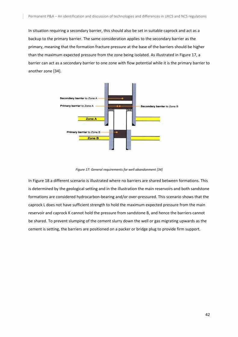
Permanent P&A – An identification and discussion of technologies and differences in UKCS and NCS regulations
42
In situation requiring a secondary barrier, this should also be set in suitable caprock and act as a
backup to the primary barrier. The same consideration applies to the secondary barrier as the
primary, meaning that the formation fracture pressure at the base of the barriers should be higher
than the maximum expected pressure from the zone being isolated. As illustrated in Figure 17, a
barrier can act as a secondary barrier to one zone with flow potential while it is the primary barrier to
another zone [34].
Figure 17: General requirements for well abandonment [34]
In Figure 18 a different scenario is illustrated where no barriers are shared between formations. This
is determined by the geological setting and in the illustration the main reservoirs and both sandstone
formations are considered hydrocarbon-bearing and/or over-pressured. This scenario shows that the
caprock L does not have sufficient strength to hold the maximum expected pressure from the main
reservoir and caprock K cannot hold the pressure from sandstone B, and hence the barriers cannot
be shared. To prevent slumping of the cement slurry down the well or gas migrating upwards as the
cement is setting, the barriers are positioned on a packer or bridge plug to provide firm support.

Permanent P&A – An identification and discussion of technologies and differences in UKCS and NCS regulations
43
Figure 18: Illustration of geological setting for permanent barriers [34]
4.2.4.3 Length requirements
The UK guideline states that good industry practise is to have at least 100ft (⁓30,5m) measured
depth (MD) of good cement but in general, where it is possible, 500ft(⁓152,5m) MD are set. The
primary barrier should contain good cement over an interval of at least 100ft MD above the highest
point of potential inflow.
If distinct zones with flow potential are less than 100ft MD apart, then the maximum practical
interval of cement should be placed between them.
For wells where the casing is part of the barrier, there should be at least 100ft MD of cumulative
good cement on both the inside and outside of the casing which must be adjacent to each other.
In situations where two barriers are replaced by a combined one the requirements are similar to the
ones mentioned above, with the difference that the length is now an interval of at least 200ft (⁓62m)
MD good cement to act as permanent barrier. An 800ft (⁓244m) MD interval is generally set. The two
different situations are illustrated in Figure 19.

Permanent P&A – An identification and discussion of technologies and differences in UKCS and NCS regulations
44
Figure 19: Length requirements for permanent barriers [34]
4.2.4.4 Open hole requirements
The guideline describes four different scenarios for open hole P&A where both dual barrier solution
and combination barrier solution is shown. The requirements outlined in previous sections apply for
open hole abandonment but there exist different ways of implementing them depending on the
conditions found downhole. There is a requirement to set a permanent barrier in cased hole or
extending at least 100ft of good cement into cased hole and this barrier shall fully isolate the open
hole and allow for a pressure test. If the permanent barrier is not set in a cased hole, a risk
assessment should be performed.
The first scenario outlined in the guideline is when the permanent barriers are fully set in the cased
hole as seen in Figure 20. This is allowed due to the potential internal pressure not exceeding the
casing shoe fracture pressure.
Figure 20: Open hole P&A where internal pressure is less than casing shoe fracture pressure [34]

Permanent P&A – An identification and discussion of technologies and differences in UKCS and NCS regulations
45
The second scenario illustrated in Figure 21 is an example of a well with two flow potential zones in
different pressure regimes which need isolation from each other but where the potential pressure
from zone A does not exceed the casing shoe fracture pressure. Generally, each zone should have
two permanent barriers each but as the pressure from zone A is lower than the casing shoe fracture
pressure it is sufficient to have only one permanent barrier between the two zones.
Figure 21: Example of open hole barriers where two zones need isolation from each other but does not exceed the casing
shoe fracture pressure [34]
The third scenario, Figure 22, illustrates open hole permanent barriers where the potential internal
pressure exceeds the casing shoe fracture pressure. In this case, two permanent barriers are required
within the open hole (with the potential internal pressure not exceeding the fracture pressure at the
base of the barriers) in addition to a barrier set somewhere within the casing to fully seal the open
hole. The topmost barrier can be compared to the surface barrier found in NORSOK D-010
.
Figure 22: Example of open hole barrier where potential internal pressure exceeds casing shoe fracture pressure [34, 36]

Permanent P&A – An identification and discussion of technologies and differences in UKCS and NCS regulations
46
The fourth and final scenario outlined in the UK guideline is the case when a side-track to the original
wellbore exists with abandoned open hole section, as seen in Figure 23. In this case an open hole has
been side-tracked and cased across the kick-off point without achieving a top of cement into
previous shoe. Then a cased hole barrier should be set above the side-track point. If a cased hole
barrier to the side-track is not installed, a risk assessment should be done for the final abandonment
of the well.
Figure 23: Example of side-tracked well with open hole section [34]
4.2.4.5 Cased hole requirements
According to the UK guideline, cemented casing cannot act as a permanent barrier in the lateral
direction due to potential poor cement jobs that results in leakages through the cement sheet as
illustrated in Figure 24. However, cement casing is considered satisfactory as barrier in the vertical
direction if there is sufficient confidence in the quantity and quality of the annulus cement. An
interval of 100ft MD of good cement in the annulus is considered sufficient for it to act as a
permanent barrier.

Permanent P&A – An identification and discussion of technologies and differences in UKCS and NCS regulations
47
Figure 24: Casing alone is not accepted as lateral permanent barrier [34]
TOC in the annulus can be verified by different logging tools or by documentation of the original
cement job (i.e. measured volumes, differential pressure, etc.). If the original documentation is
used for verification, it requires a longer cement column in annulus to account for uncertainty. In
this case, the cement column in annulus should extend 1000 ft. (⁓305m) above the base of the
primary permanent barrier. This length may be reduced or increased depending on the
confidence in TOC for each well.
If the records show any problems during the initial cement job or in the wells life cycle, it may
indicate lacking annulus barrier. In this case, remedial actions may be necessary to ensure the
quality of the cement behind the casing. Such actions may be retrieving the casing, placing
cement in annulus by perforating or circulating, or section milling.
An overview over a cased hole abandonment is illustrated in Figure 25. The general requirement
is that formations should be internally separated by one permanent barrier. However, if cross-
flow is deemed acceptable (e.g. formations within same pressure regime) it is not necessary to
install barriers between the different zones as seen in the figure. In the figure, the annulus
cement is illustrated with two different scenarios. One where TOC has been determined by
differential pressure or monitored volumes measured during the original cement job (1000ft to
allow for uncertainty), and the other for TOC verified by logs (100ft column).
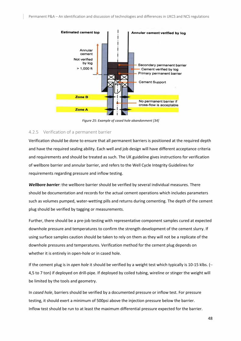
Permanent P&A – An identification and discussion of technologies and differences in UKCS and NCS regulations
48
Figure 25: Example of cased hole abandonment [34]
4.2.5 Verification of a permanent barrier
Verification should be done to ensure that all permanent barriers is positioned at the required depth
and have the required sealing ability. Each well and job design will have different acceptance criteria
and requirements and should be treated as such. The UK guideline gives instructions for verification
of wellbore barrier and annular barrier, and refers to the Well Cycle Integrity Guidelines for
requirements regarding pressure and inflow testing.
Wellbore barrier: the wellbore barrier should be verified by several individual measures. There
should be documentation and records for the actual cement operations which includes parameters
such as volumes pumped, water-wetting pills and returns during cementing. The depth of the cement
plug should be verified by tagging or measurements.
Further, there should be a pre-job testing with representative component samples cured at expected
downhole pressure and temperatures to confirm the strength development of the cement slurry. If
using surface samples caution should be taken to rely on them as they will not be a replicate of the
downhole pressures and temperatures. Verification method for the cement plug depends on
whether it is entirely in open-hole or in cased hole.
If the cement plug is in open hole it should be verified by a weight test which typically is 10-15 klbs. (⁓
4,5 to 7 ton) if deployed on drill-pipe. If deployed by coiled tubing, wireline or stinger the weight will
be limited by the tools and geometry.
In cased hole, barriers should be verified by a documented pressure or inflow test. For pressure
testing, it should exert a minimum of 500psi above the injection pressure below the barrier.
Inflow test should be run to at least the maximum differential pressure expected for the barrier.
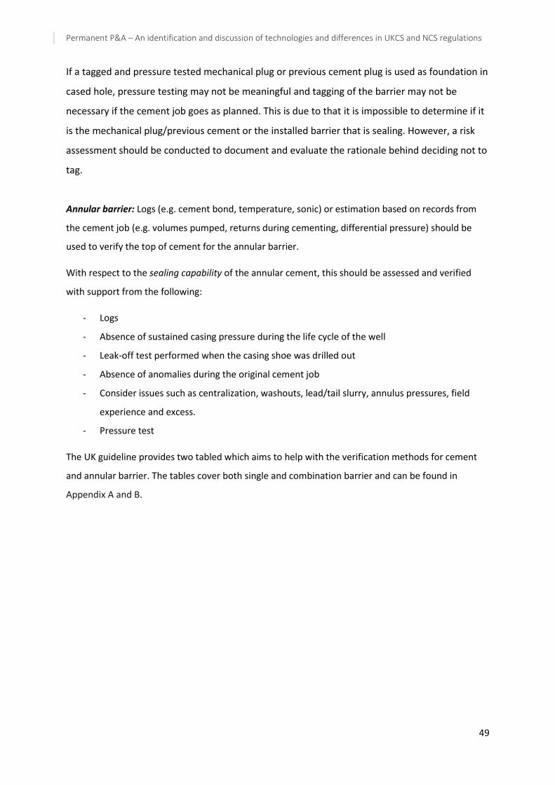
Permanent P&A – An identification and discussion of technologies and differences in UKCS and NCS regulations
49
If a tagged and pressure tested mechanical plug or previous cement plug is used as foundation in
cased hole, pressure testing may not be meaningful and tagging of the barrier may not be
necessary if the cement job goes as planned. This is due to that it is impossible to determine if it
is the mechanical plug/previous cement or the installed barrier that is sealing. However, a risk
assessment should be conducted to document and evaluate the rationale behind deciding not to
tag.
Annular barrier: Logs (e.g. cement bond, temperature, sonic) or estimation based on records from
the cement job (e.g. volumes pumped, returns during cementing, differential pressure) should be
used to verify the top of cement for the annular barrier.
With respect to the sealing capability of the annular cement, this should be assessed and verified
with support from the following:
- Logs
- Absence of sustained casing pressure during the life cycle of the well
- Leak-off test performed when the casing shoe was drilled out
- Absence of anomalies during the original cement job
- Consider issues such as centralization, washouts, lead/tail slurry, annulus pressures, field
experience and excess.
- Pressure test
The UK guideline provides two tabled which aims to help with the verification methods for cement
and annular barrier. The tables cover both single and combination barrier and can be found in
Appendix A and B.

Permanent P&A – An identification and discussion of technologies and differences in UKCS and NCS regulations
50
4.2.6 Special considerations for abandonment
The UK guideline mentions several special considerations for P&A, being more thorough than
NORSOK D-010 and these will be outlined in this section.
4.2.6.1 Well design
There exist clear regulations in the UK [36] which states that a well shall be designed and constructed
so that as far as it is reasonable practicable it can be suspended or abandoned in a safe manner and
there can be no unplanned escape of fluids from it or the reservoir beneath it after
abandonment/suspension. In addition, the UK guideline states that the key to a simple abandonment
is the initial well design and that well-operators must consider abandonment as part of the design
and modification to account for future effects of the decisions.
4.2.6.2 Partial abandonment for side-tracking or for other reasons
The requirements for barrier explained in the previous sub-section applies to the original wellbore
when side-tracking but the guideline allows for temporary abandonment if there is high confidence
that permanent barrier can be set when final permanent abandonment of the entire well.
4.2.6.3 HPHT wells
The UK guidelines states that in addition to following the requirements outlined for standard wells,
due to the increasing complexity and criticality of these types of wells there should be special
emphasis on recharging to high pressure, caprock depletion, thin pressure transition zone, liner
deformation, temperature cycling and subsidence etc.
4.2.6.4 Multilateral wells
The following considerations may be valid for multilateral wells:
- Future abandonment in the well design as it might be very difficult to regain access to the
wellbore
- The lateral branches might have different pressure regimes
- Cementing off annuli above the laterals (as barriers might already be installed here)
4.2.6.5 Overburden competence due to reservoir compaction/subsidence
When selecting the position and properties of permanent barriers there should be a risk assessment
conducted which assess the overburden formations and whether they are prone to formation
compaction and/or subsidence of the seabed.
4.2.6.6 High angle and horizontal wells
P&A of horizontal and high angle wells are in principle the same as standard wells. A high angle well
is defined as a well having an angle higher than 70o. The difference is that it is more difficult to

Permanent P&A – An identification and discussion of technologies and differences in UKCS and NCS regulations
51
achieve satisfactory isolation and the means of ensuring isolation differs. The main problem is
situations where there is more than one zone with potential flow. To account for this situation, the
completion design should consider future abandonment and in general the abandonment
requirements should be established at the planning/completion design phase of the well. The zones
may then be isolated in accordance with the guidelines with minimum effort.
If there is only one zone with flow potential, a mechanical device such as a bridge plug is set just
above the start of the reservoir with a cement plug on to as a first permanent barrier. It must extend
to the full cross-section. This is illustrated in Figure 26 below.
Figure 26: Abandonment of high angle well [34]
4.2.6.7 Sealing formations
Over time, some formations are known to move due to stress differences. These formations can be
accepted as replacement for good cement in annulus if it can be demonstrated that the seal against
the casing is impermeable and have sufficient strength to withstand the anticipated future pressures.
The qualification for using formation as seal in a well should be documented and requires:
1. Documentation that the formation has sufficient fracture strength to hold against the
expected future pressures.
2. Verify that the seal has an interval of at least 100ft per barrier where the bond log response
must be equivalent to good cement or better. This must be verified by two independent
logging tools and interpreted by a qualified log specialist.
3. Validation that at the anticipated future pressures the bond log response can be interpreted
as not leaking. A means of achieving this is to run a pressure test between 100ft spaced
perforations.

Permanent P&A – An identification and discussion of technologies and differences in UKCS and NCS regulations
52
4.2.6.8 Liner laps
According to the guideline a liner lap should not be part of a permanent barrier unless at least 100ft
of good cement has been verified across it, as it is for all barriers. If the cement quality in the liner lap
cannot be assured, the barrier should be set above or below it. Figure 27 illustrates liner lap
cementation.
The reason is that common practice makes it impossible to distinguish whether it is the packer or the
liner lap holding the pressure as the packer is set straight after cementation and they are tested
together. This is sufficient for the production life but it not considered adequate for permanent
abandonment barriers.
Figure 27: Liner lap cementation [34]
4.2.6.9 Trough-tubing abandonments
Through tubing abandonments is when well completions are left in the hole and permanent
barriers are to be installed through and around the tubular. In these situations, reliable methods
and procedures for barrier placement and verification should be established. Allowances should
be made for the possibility of cement slumping or fingering in the annuli to ensure full cross-
sectional barrier. There is no accurate method available for determining TOC in both tubing and
annulus, and thus a method of tagging combined with quality control through e.g.
measurements of cement job and pressure testing of both annulus and tubing is recommended.
Figure 28 illustrates an example of through-tubing abandonment where a combination barrier is
used. Barriers in the A-annulus is set by punched tubing (induced holes in tubing followed with

Permanent P&A – An identification and discussion of technologies and differences in UKCS and NCS regulations
53
cement squeezing). Since there are no logs that can log through multiple strings, 1000ft MD of
cement is recommended in B-annulus if verification is based on other information that logs.
Figure 28: Through-tubing abandonment [34]
4.2.6.10 Removal of subsea equipment
When permanently abandoning a well there should be no redundant subsea equipment left which
can present hazards to other users of the sea. Retrieval of all casing strings to a minimum of 10ft
below seabed is seen as good practise but must be reviewed on individual well basis accounting for
local conditions such as sand waves and scouring. Where practicable all subsea equipment and debris
should be removed and a seabed clearance certificate should be issued. If there are any large
structures permanently left at seabed in vicinity of the well (e.g. concrete) no casing strings should
extend above the remaining structure.
4.2.6.11 Additional special requirements
In addition to the requirements mentioned separately above, the UK guideline provides some advice
or reference to the following issues:
- Irretrievable radioactive sources; advice should be sought from the Environmental Agency or
Scottish Environment Protection Agency (SEPA).
- Casing cuts; trapped gas or sources of pressure may be present behind the casing and
precaution should be taken before cutting the casings. Also, as casings usually are in tension,
cutting it will cause the lower part to drop which may result in trapped gas to be released.

Permanent P&A – An identification and discussion of technologies and differences in UKCS and NCS regulations
54
- Removal of downhole equipment; provided the required isolations in the guidelines are
achieved it is not required to remove downhole equipment.
- Control lines, ESP, gauge cables; these components should not be part of the permanent
barriers as they may be potential leak paths. Hence, they should be removed (at least for the
intervals where the barriers are set)
- Wells containing H2S; the barriers should be chosen and designed to withstand the corrosive
environment
- Wells containing CO2; applies to wells naturally containing CO2. The barriers should be
chosen to withstand the potential effects the gas can have on cement (degradation in
presence of water), steel components (corrosion) and subsurface formations (thermal
fracturing).
- Wells containing magnesium salts; magnesium salts are a potential risk as it may degrade the
cement by lowering its mechanical strength and increase its permeability.
- Gas wells and high gas oil ratio (GOR) wells; these types of wells have an additional concern
in potential gas migration through barriers and it is recommended that barrier material and
deployment technique is carefully chosen.
- Annular fluids; Fluids that cannon be legally discharged and are located in the uppermost
section of the well should be removed or contained before removal of wellhead as this will
expose them to the environment.
- Shallow water-bearing zones; in some cases it will be necessary to isolate shallow water-
bearing zones in a well but this depend on local conditions and need to be evaluated on a
well-by-well basis.
- Hydrocarbons of biogenic nature; this is hydrocarbons which are found anywhere and
originates from shallow formations. The presence of these substances does not necessarily
indicate a barrier failure. Composition analysis can be run to identify the biogenic
hydrocarbons and evaluate whether there is any indication of barrier failure or not.
- Trawlability; as partially abandoned wells (phase 1 and 2) normally does not have exclusion
zones (500m) it is important to notify relevant agency of the presence of a wellhead.
Wellhead protection should be considered to provide protection for both wellhead and
trawlers depending on local conditions.
4.2.7 Phases of well abandonment
The UK guideline separates the abandonment of wells into 3 different phases which are distinguished
by the operations performed and installation of barriers [34].

Permanent P&A – An identification and discussion of technologies and differences in UKCS and NCS regulations
55
Abandoned Phase 1: The reservoir has been permanently isolated which requires that barrier
material is positioned to permanently isolate all reservoir zones used for production or injection from
the wellbore. The tubing may be left in place, partially or fully retrieved.
Abandoned Phase 2: All intermediate zones with flow potential have been permanently isolated.
This phase is completed when there is no need for further permanent barriers meaning that tubing
may need to be pulled if not done already in addition to isolating liners, milling (if necessary),
retrieve casing and setting a permanent barrier (cement or other material).
Abandoned Phase 3: After removal of wellhead and conductor the well is considered to be fully
abandoned and it is never to be re-entered or used again. The well origin at surface is removed and
so is any subsea equipment.
4.2.7.1 Well re-entry considerations
“Phase 1 and phase 2 abandonment must be carried out so that the well can be re-entered safely,
and then secured using pressure control equipment without compromising the barriers in place.”
[34]. In order to make re-entry of the well as smooth as possible, consideration should be given to
ensure sufficient depth of the shallowest barrier.
4.2.7.2 Inspection scheme for phase 1 and phase 2 abandoned wells
Regulation 18 in DCR [36] requires all well-operators to perform well examination on all wells. This
applies throughout a wells life cycle and thus operators should consider physical inspection schemes
for phase 1 and 2 of abandonment.
4.2.8 Appendices
The UK guideline contain 7 appendices, A-G, which provides additional information on topics
mentioned within the document. The appendices provide information regarding the following:
Appendix A – Statutory notifications, approvals and record keeping: states which regulations apply
for the different issues such as HSE, permits that may be required and Oil and Gas authority
requirements.
Appendix B – Basic well data required for well abandonment: this include parameters such as well
configurations, the stratigraphic sequence of each wellbore with information about reservoir fluids
and pressures, logs etc from primary cementing job, estimated future formation fracture gradient
and specific well conditions like scale, collapse casing and so on. These are the same as for NORSOK
D-010.

Permanent P&A – An identification and discussion of technologies and differences in UKCS and NCS regulations
56
Appendix C – Barrier integrity – potential issues and mitigations: this appendix provides examples of
potential issues and possible mitigating measures that well-operators may consider when performing
a risk assessment. The list (table) should be used in combination with good engineering judgement as
it cannot cover every possible scenario that may arise.
Appendix D – P&A code: the guideline includes a P&A code which is used to categorize the work
scope of plug and abandonment operations. It is valid for any well and all work phases and is used for
high level cost estimation and benchmarking. More on this P&A code is outlined in subsection 0 on
the cost estimation guideline.
Appendix E – Irretrievable radioactive sources – SEPA: Gives instruction on how to deal with radiation
sources located within the well and which agencies that should be notified.
Appendix F – References and further reading
Appendix G – Background to the guidelines
4.2.9 Guidelines on Well Abandonment Cost Estimation
In addition to the guidelines for the abandonment of wells and material qualification, Oil and Gas UK
has also issued a guideline for the cost estimation of well abandonment [37]. This is a document of
41 pages which covers cost estimation techniques in different scenarios for both well and entire
fields and a classification system for wells (P&A code). The current document is the 2nd issue and was
published in 2015. The aim of the guideline is to give specific guidance on how to estimate well
abandonment cost as a subset to the overall estimates in the Decommissioning guidelines. The
guideline is fairly extensive and therefore this thesis will be limited to presenting the highlights of the
document.
The objective of the guideline is to outline best practise based on industry experience and aid UK
operators of both offshore and onshore wells to generate good estimates by providing the following
[37]:
- A template that operators can use to prepare their well abandonment cost estimates.
- A checklist of activities in order that an estimate can built on which is both consistent and
complete.
- A methodology which requires that duration of activity and market rates are clearly
understood and stated in the cost estimate.

Permanent P&A – An identification and discussion of technologies and differences in UKCS and NCS regulations
57
- Recognition that more detailed estimates will be required as Cessation of Production (COP) is
getting closer.
- Aiding in creating a greater level of confidence when determining decommissioning costs for
asset acquisition or divestment.
- Provide a basis for comparing estimates from different sources and capture the operators
experience.
- A framework for benchmarking
4.2.9.1 Regulatory Requirements
The cost guideline states that all activities shall be in accordance with the governing accounting
protocols and standards in use in the country the company is registered. The offshore oil and gas
sector is governed by the Petroleum Act 1998, which says that the obligation for decommissioning
offshore infrastructure belongs to the owners of the site. As part of decommissioning responsibilities,
companies have to include cost estimations in their normal accounting process where the accuracy
of the estimates increases as the abandonment date approaches. The Petroleum Act 1998 states that
an abandonment programme shall include a cost estimate of the activities and it shall either specify
the time/time interval for the measures to be taken or make provision with regards to how the times
are to be determined. Further, the regulations stated in UK Guidelines for abandonment of wells
shall be followed.
4.2.9.2 Well abandonment cost estimation
For the cost estimation process the guideline emphasises that the guideline provides guidance on
what should be considered when generating estimates through tables without including decisive
numbers. It further states that uncertainties must be taken into account and all background
documents and assumptions made must be recorded. It also put emphasis on the fact that the
estimates will change over time and that they become more accurate as the end of production is
approaching.
In relations to estimates accuracy the guideline acknowledges that the level of detail and accuracy
will need to increase as the cessation of production (COP) approaches. In UK, discussions of P&A
proposals typically commence with the Department of Energy & Climate Change 2-3 years prior to
anticipated COP, leading to the submission of the Decommissioning Programme. Because of this, first
planning may need to start at least 5 years in advance of COP, and with quite detailed cost estimates.
This is illustrated in Table 5 below which is copied from the cost estimation guideline [37].

Permanent P&A – An identification and discussion of technologies and differences in UKCS and NCS regulations
58
Table 5: Level of accuracy required as COP approaches [37]
Incr
easi
ng
leve
l of
accu
racy
req
uir
ed
Time to COP
Approach recommended to review wells
Proportion of wells required
for review
Expected accuracy
range
> 10 years
Field-wide review of representative wells
10-25% -30% to
+50%
5 to 10 years
Well-by-well review of sample to define concept design
All -15% to
+30%
< 5 years
Detailed, full, well-by-well review. Timing of abandonment
phases may need to be considered
All -15% to
+15%
Imminent Detailed well-by-well review of
status, integrity, work units required + services cost
All -5% to +15%
For AFE AFE estimates are out with the
scope of the guidelines All
4.2.9.3 Classification System for well abandonment
As mentioned previously the UK guidelines provides a means of classifying wells based on location,
abandonment complexity and abandonment phases. This is done to establish a common approach
for all operators to limit the potential misunderstandings which may arise from different approaches
being used. The method is called P&A coding and it consist of 2 letters followed by 3 digits. The two
letters indicate the location of the well and the three digits represent the phase and complexity of
each phase.
Location:
- PL – platform well
- SS – subsea well
- LA – land well
Phases: the phases are separated as outlined in 4.2.7.
Complexity: the complexity is divided into 5 types depending on the work required.
- Type 0 – No work required. A phase or phases of abandonment work may already have been
completed
- Type 1 – Simple rig-less abandonment. Using wireline, pumping, crane, jacks. Subsea will use
light well intervention vessel and be riser-less.
- Type 2 – Complex rig-less abandonment. Using CT, HWU, wireline, pumping, crane, jacks.
Subsea will use heavy duty well intervention vessel with riser.
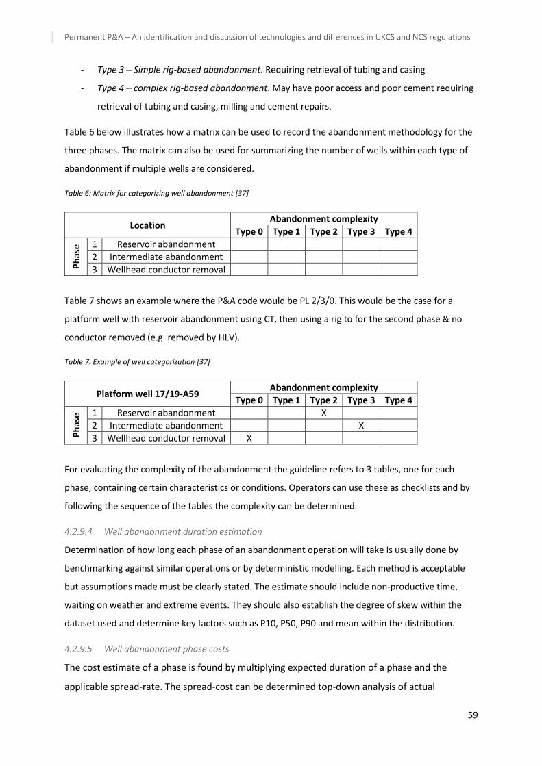
Permanent P&A – An identification and discussion of technologies and differences in UKCS and NCS regulations
59
- Type 3 – Simple rig-based abandonment. Requiring retrieval of tubing and casing
- Type 4 – complex rig-based abandonment. May have poor access and poor cement requiring
retrieval of tubing and casing, milling and cement repairs.
Table 6 below illustrates how a matrix can be used to record the abandonment methodology for the
three phases. The matrix can also be used for summarizing the number of wells within each type of
abandonment if multiple wells are considered.
Table 6: Matrix for categorizing well abandonment [37]
Location Abandonment complexity
Type 0 Type 1 Type 2 Type 3 Type 4
Ph
ase
1 Reservoir abandonment
2 Intermediate abandonment
3 Wellhead conductor removal
Table 7 shows an example where the P&A code would be PL 2/3/0. This would be the case for a
platform well with reservoir abandonment using CT, then using a rig to for the second phase & no
conductor removed (e.g. removed by HLV).
Table 7: Example of well categorization [37]
Platform well 17/19-A59 Abandonment complexity
Type 0 Type 1 Type 2 Type 3 Type 4
Ph
ase
1 Reservoir abandonment X
2 Intermediate abandonment X
3 Wellhead conductor removal X
For evaluating the complexity of the abandonment the guideline refers to 3 tables, one for each
phase, containing certain characteristics or conditions. Operators can use these as checklists and by
following the sequence of the tables the complexity can be determined.
4.2.9.4 Well abandonment duration estimation
Determination of how long each phase of an abandonment operation will take is usually done by
benchmarking against similar operations or by deterministic modelling. Each method is acceptable
but assumptions made must be clearly stated. The estimate should include non-productive time,
waiting on weather and extreme events. They should also establish the degree of skew within the
dataset used and determine key factors such as P10, P50, P90 and mean within the distribution.
4.2.9.5 Well abandonment phase costs
The cost estimate of a phase is found by multiplying expected duration of a phase and the
applicable spread-rate. The spread-cost can be determined top-down analysis of actual

Permanent P&A – An identification and discussion of technologies and differences in UKCS and NCS regulations
60
abandonment data or by bottom-up analysis from the assumed utilisation and cost/day of the
required equipment. The assumptions made must be stated, for instance if current of expected
rig rates are used.
4.2.9.6 Field well abandonment cost
Once a well has been evaluate and given associated estimates for costs related to location, phases,
complexity and phase spread cost it is fairly simple to integrate the factors to determine a likely
duration and cost for the abandonment of the well and summarizing all wells to get an estimate for
the entire field. The process can be summarized as illustrated in Figure 29.
Figure 29: Illustration of cost estimation process [37]

Permanent P&A – An identification and discussion of technologies and differences in UKCS and NCS regulations
61
4.3 DNV GL – RP-E103 – Risk based abandonment of offshore wells
In April 2016 DNV GL published a new, globally applicable recommended practice (RP) for
permanently abandoned well which gives a risk-based perspective on P&A. This is a contrast to the
traditional prescriptive methodology demonstrated in the previously described standard and
guidelines. The background for developing a different approach to P&A is that no wells are equal and
DNV GL suggest that they do not all need the same number, type and size of barriers to be deemed
safe and protect the environment. By introducing a risk-based approach, tailor-made design solutions
can be made which better fits the different wells and allow cost-savings to be gained for the least
critical wells. Estimates suggest potential cost savings of more than USD32bn on the NCS alone, and
even more globally [38]. Systematic assessment of the well abandonment design against defined
acceptance criteria to ensure safety to environment and maintain safety standards is the objective of
performing a risk-based abandonment assessment.
“The recommended practise is intended to provide an alternative approach, based on functional
requirements and risk acceptance criteria to assess abandonment designs. This is consistent with
offshore engineering practice and is intended to facilitate cost efficient solutions including the
development of new technology. By calculating the risk levels for the proposed solutions and cross-
checking them with the risk acceptance criteria, more cost-effective solutions can be identified and
implemented. “ [39].
Advantages to the methodology are that it has:
- Explicit criteria for environmental protection
- P&A spending concentrated on higher-risk wells
- The ability to optimise well abandonment design
- Flexibility to implement new plugging technology in the future
- Site specific considerations
The RP is divided in 2 sections where the first section is an introduction and the second is a risk
assessment framework for well abandonment.
4.3.1 Section 1 – introduction
In general, the RP is meant to be a basis for decision-making and it presents practices and principles
for:
- establishing site specific environmental risk acceptance criteria
- confirming compliance with safety criteria for the installation/field
- how to determine the functional requirements for materials used in permanent well barriers

Permanent P&A – An identification and discussion of technologies and differences in UKCS and NCS regulations
62
- how to differentiate the environmental risk exposure relative to hydrocarbon composition.
The RP covers permanently abandoning offshore wells and is not applicable for neither onshore,
suspended or temporarily abandoned wells. The requirements presented are intended to be
subordinate to local regulations.
The RP differentiate between the three verbal forms shall, should and may.
Shall – indicates a mandatory requirement to be followed for fulfilment of compliance with the RP.
Should – verbal form used to indicate that among several possibilities one is recommended as
particularly suitable, without mentioning or excluding others, or that a certain course of action is
preferred but no necessarily required.
May – indicate a course of action permissible within the limits of the document.
The definition of these verbal forms is equal to the NORSOK D-010 definitions of the same terms.
4.3.1.1 System description
The RP gives a description of the systems referred to in the RP which include offshore wells, their
surrounding geology and marine environment. This is illustrated in Figure 30, copied from RP-E103.
Marine environment: The marine environment includes the seafloor, the water column and the sea
surface. All wells interact with the marine environment to some degree, including abandoned wells.
When wellbores are in place they create a preferred pathway for gas migration which results in
natural seepage tending to concentrate around wells. Seepage can also occur from hydrocarbon
located deeper in the well, and the main focus for P&A is to prevent the heavier hydrocarbons from
reaching the marine environment. Hydrocarbons may be naturally occurring in the ecology, i.e.
methane gas which provides nutrition, or they may be heavier types for which there is a limit for how
much is allowed in seawater/sediment.
Geology: The geological sequence above an oil or gas reserovir is referred to as overburden, which
may contain quantitites of hydrocarbons in certain formations. Hydrocarbons, as well as all pore
fluids, are able to move within the geological sequence but is limit by sealing formations that have
low permeability relative to other formations. These seals may be compromised by natural processes
such as faulting or overpressure, or they could be man-made by drilling activity.
Wellbore: The wellbore provides a conduit for production from, or injection to a reservoir. A well
penetrates the overburden when accessing a reservoir and it provide a potential passageway for
pore fluids to migrate to the seabed.
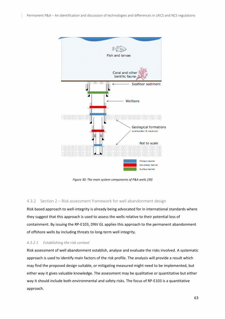
Permanent P&A – An identification and discussion of technologies and differences in UKCS and NCS regulations
63
Figure 30: The main system components of P&A wells [39]
4.3.2 Section 2 – Risk assessment framework for well abandonment design
Risk based approach to well-integrity is already being advocated for in international standards where
they suggest that this approach is used to assess the wells relative to their potential loss of
containment. By issuing the RP-E103, DNV GL applies this approach to the permanent abandonment
of offshore wells by including threats to long-term well integrity.
4.3.2.1 Establishing the risk context
Risk assessment of well abandonment establish, analyse and evaluate the risks involved. A systematic
approach is used to identify main factors of the risk profile. The analysis will provide a result which
may find the proposed design suitable, or mitigating measured might need to be implemented, but
either way it gives valuable knowledge. The assessment may be qualitative or quantitative but either
way it should include both environmental and safety risks. The focus of RP-E103 is a quantitative
approach.

Permanent P&A – An identification and discussion of technologies and differences in UKCS and NCS regulations
64
It is important to establish the context before any of the elements included in the risk assessment
period is started/executed. The context should also be updated throughout the process. For P&A
purposes, an evaluation of flow potential of the producing reservoir, in-situ formations and between
formations (cross-flow) as well as permanent well barrier solutions should be performed.
Figure 31 illustrates the main elements in a well abandonment risk assessment and the main
categories for input are:
- Well specific data
- Geology data
- Environmental data
- Met-ocean data
The RP provides a sample input of data in its appendix which is copied and showed in Appendix C.
When performing the risk assessment, documentation of the activities should be provided in a
manner which is traceable, transparent and consistent. The assumptions, inputs and results of the
analysis should be quality assured as part of the risk assessment.
Figure 31: Risk Context for P&A [39]

Permanent P&A – An identification and discussion of technologies and differences in UKCS and NCS regulations
65
4.3.2.1.1 Well abandonment design
With regards to the well abandonment design RP-E103 states that the main objective should be to
prevent environmental harm until the original geological barriers are re-established at the same time
as ensuring safety standards are satisfied. The design should be as detailed as reasonably practicable,
be based on the risk context and maximum expected flow and it should be recognized that all wells
are unique when abandoning multiple wells.
4.3.2.1.2 Flow potential sources
An overview of formations that identifies, examines and describes hydrocarbon-bearing formations
with their associated flow potential should be made. In this context, flow potential is defined as “a
hydrocarbon-bearing formations containing moveable hydrocarbons large enough to have a potential
environmental or safety impact.”[39]. Table 8 shows how the flow potential should be categorized.
The categorization should be performed for a distribution of the expected flow potential for the
identified hydrocarbon-bearing formations, including re-charge, re-development for hydrocarbon
extraction or other issues such as geothermal project and storage of energy or CO2. Potential
consequences to the environment should be mitigated with permanent well barriers in compliance
with ALARP principles for formations categorized with moderate or significant flow potential. The RP
refers to the UK Oil & Gas Guidelines for the Abandonment of wells for further guidelines on this
subject.
For multiple hydrocarbon-bearing formations located within the same pressure regime, they may be
treated as one formation if the cross-flow is in accordance with the environmental acceptance
criteria. In general, cross-flow between formations should be prevented.
Table 8: Categorization of flow potential in hydrocarbon-bearing formations
Categories of flow potential
Definition
No or limited flow potential
Hydrocarbon-bearing formations where moveable hydrocarbons present or in the future cannot under any circumstances have an environmental or safety impact
Moderate flow potential
Hydrocarbon-bearing formations where moveable hydrocarbons present or in the future may have an environmental impact, but no safety impact
Significant flow potential
Hydrocarbon-bearing formations where moveable hydrocarbons present or in the future may have both environmental and safety impact
4.3.2.1.3 Permanent well barrier principles
When designing the permanent well barrier, it should be made fit-for-purpose and consider the
effects of any reasonable foreseeable chemical and geological processes. The function of a

Permanent P&A – An identification and discussion of technologies and differences in UKCS and NCS regulations
66
permanent well barrier is to control formations with moderate or significant flow potential, the
duration requirement for the barrier should be site specific and depend on the barrier’s design. One
element of the permanent well barrier should be the surrounding formation which should have a
higher integrity than the potential pressure below it and be impermeable at the depth of the barrier.
Depth requirement to the barrier is that the formation should be strong enough to contain the
hydrocarbon-bearing formations. The barrier may consist of any material or combination of WBE
provided it fulfil the following functionalities [39]:
- withstand the maximum anticipated combined loads to which it can be subjected
- function as intended in the environments (pressures, temperature, fluids, mechanical
stresses) that can be encountered
- prevent unacceptable hydrocarbon flow to the external environment.
Comment: The RP use the phrasing “any reasonable foreseeable” and not the phrasing “eternity” for
describing the permanent well barrier design – different to NORSOK. Is also states duration of barrier
should be site specific – not eternal perspective
4.3.2.1.4 Number of well barriers
The illustrations in Figure 32 below shows examples of different well abandonment design with
different flow potentials. As seen in the figure the number of barrier depend on how big the flow
potential is, which is evaluated based on risk analysis. The RP recognizes that having multiple
independent barriers can increase the level of reliability. The primary and secondary barrier can be
combined into a single barrier provided it maintains the same level of effectiveness and reliability as
two individual would. There should also be a surface barrier in place to isolate flows from the
wellbore in addition to the primary and secondary barrier
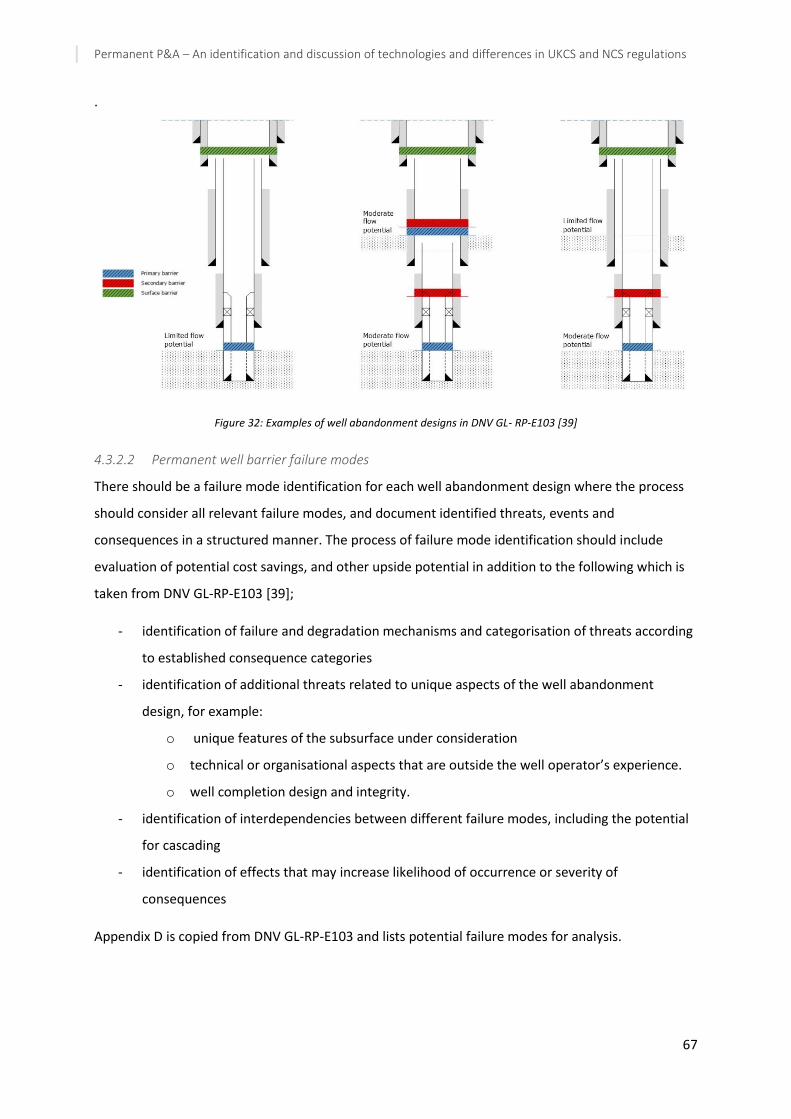
Permanent P&A – An identification and discussion of technologies and differences in UKCS and NCS regulations
67
.
Figure 32: Examples of well abandonment designs in DNV GL- RP-E103 [39]
4.3.2.2 Permanent well barrier failure modes
There should be a failure mode identification for each well abandonment design where the process
should consider all relevant failure modes, and document identified threats, events and
consequences in a structured manner. The process of failure mode identification should include
evaluation of potential cost savings, and other upside potential in addition to the following which is
taken from DNV GL-RP-E103 [39];
- identification of failure and degradation mechanisms and categorisation of threats according
to established consequence categories
- identification of additional threats related to unique aspects of the well abandonment
design, for example:
o unique features of the subsurface under consideration
o technical or organisational aspects that are outside the well operator’s experience.
o well completion design and integrity.
- identification of interdependencies between different failure modes, including the potential
for cascading
- identification of effects that may increase likelihood of occurrence or severity of
consequences
Appendix D is copied from DNV GL-RP-E103 and lists potential failure modes for analysis.

Permanent P&A – An identification and discussion of technologies and differences in UKCS and NCS regulations
68
4.3.2.3 Risk analysis
The aim of a risk analysis is to increase understanding of risks meaning the characteristics of the risk
itself, the likelihood of occurrence and the severity of the potential consequences. For P&A purposes
the risk analysis should include safety and environmental risks and should be performed on the
failure modes identified. If reliable sources of data are available they should be incorporated in the
analysis and if there is limited data, or the data is uncertain, assumptions may be utilized. If
assumptions are applied, they should be conservative.
The risk analysis should contain an analysis of the flow potential to determine the maximum flow
potential and hydrocarbon content/composition within formations penetrated by the well and use
this in the assessment. The objective is to estimate the magnitude of the consequence of
hydrocarbon flow. The likelihood of flow should also be part of the risk analysis in order to
characterise the identified failure modes with respect to likelihood of occurrence. Level of detail
depend on whether it is a qualitative or quantitative analysis. The RP refers to ISO 31000 for
guidance on qualitative vs. quantitative risk analyses.
The next step is to perform an analysis of the valued ecosystem components (VEC’s) which aims to
create a site-specific map and categorization of the geographical distribution of valued resources and
habitat around a well. The results are used in the risk analysis.
To calculate the transport of the identified hydrocarbon flow potential, three-dimensional dispersion
modelling should be used which calculate and records the distribution of mass and concentration of
hydrocarbons in the water and sediments. A probabilistic approach should be used to give insight on
how potential seepages will behave under a wide range of ocean conditions.
The last part of the risk analysis is to perform an impact analysis. The consequence part of the risk
picture is a combination of the results of the flow potential analysis and the dispersion modelling.
The likelihood portion is produced and incorporated in the analysis of the flow potential.
The environmental risk picture can be built by assessing the potential environmental impact from the
degree of overlap between hydrocarbon concentrations and defined VEC’s. The safety risk picture
should be compiled from the likelihood and consequence of safety risk for the well abandonment
design.
The output from the consequence analysis (flow potential, mapping and valuing of VEC’s and marine
dispersion) and the likelihood analysis gives the risk result for each specific well abandonment
design.

Permanent P&A – An identification and discussion of technologies and differences in UKCS and NCS regulations
69
4.3.2.4 Risk evaluation
After the analysis is done the results need to be evaluated against defined risk acceptance criteria
with the purpose of aiding decision-making. Re-analysis and revision of the well abandonment design
may be necessary should the result of the risk evaluation be that the design is not applicable and
measures to reduce risk are required.
Risk acceptance criteria should be made both with regards to environment and safety. The
environmental risk acceptance criteria should be based on the proportion of VEC(s) exposed to a
defined threshold value for hydrocarbons and the probability that the proportion of VEC(S) is
exposed to a concentration above the defined threshold value.
The safety risk acceptance criteria depend on whether it is a platform or subsea well. After
completing P&A on a subsea well, safety risk may not be relevant whereas for a platform well the
established risk acceptance criteria for the platform should be applied. There should be a
categorisation of wells planned to be permanent abandoned based on their potential for adverse
safety consequences.
Environmental and safety risk evaluations should be done to compare the risk acceptance criteria
and the results of the risk analysis. Various designs may be compared to the risk acceptance criteria
and to each other before deciding which solution is the optimum one, and if changes need to be
done to the design before moving forward. If changes are made, the design should go through
another risk assessment process to quantify the impact the changes have. The results may also
function as support for decision-making in a cost-benefit analysis.
4.3.2.5 Treatment of uncertainties
As with any other risk analysis there will be uncertainties present and care should be taken to ensure
that the results of the risk assessment possess reasonably accuracy. If there are significant
uncertainties present, sensitivity or scenario analyses should be performed. Depending on their
influence, critical parameters might be pressure, hydrocarbon volume and temperature.
With respect to quantification of uncertainty a set of weighted probabilities might be interpreted
through a probability distribution. How to establish a fitting distribution will depend on the
knowledge available and if it changes over time.
Available data for planning P&A should be studied for each potential well and if critical pieces of
information which may reduce uncertainties exist, it should be identified and recorded.
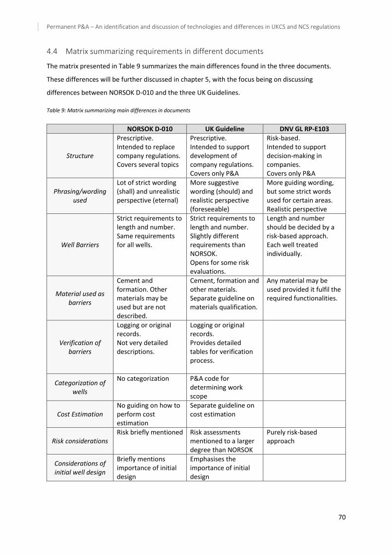
Permanent P&A – An identification and discussion of technologies and differences in UKCS and NCS regulations
70
4.4 Matrix summarizing requirements in different documents
The matrix presented in Table 9 summarizes the main differences found in the three documents.
These differences will be further discussed in chapter 5, with the focus being on discussing
differences between NORSOK D-010 and the three UK Guidelines.
Table 9: Matrix summarizing main differences in documents
NORSOK D-010 UK Guideline DNV GL RP-E103
Structure
Prescriptive. Intended to replace company regulations. Covers several topics
Prescriptive. Intended to support development of company regulations. Covers only P&A
Risk-based. Intended to support decision-making in companies. Covers only P&A
Phrasing/wording used
Lot of strict wording (shall) and unrealistic perspective (eternal)
More suggestive wording (should) and realistic perspective (foreseeable)
More guiding wording, but some strict words used for certain areas. Realistic perspective
Well Barriers
Strict requirements to length and number. Same requirements for all wells.
Strict requirements to length and number. Slightly different requirements than NORSOK. Opens for some risk evaluations.
Length and number should be decided by a risk-based approach. Each well treated individually.
Material used as barriers
Cement and formation. Other materials may be used but are not described.
Cement, formation and other materials. Separate guideline on materials qualification.
Any material may be used provided it fulfil the required functionalities.
Verification of barriers
Logging or original records. Not very detailed descriptions.
Logging or original records. Provides detailed tables for verification process.
Categorization of wells
No categorization P&A code for determining work scope
Cost Estimation No guiding on how to perform cost estimation
Separate guideline on cost estimation
Risk considerations Risk briefly mentioned Risk assessments
mentioned to a larger degree than NORSOK
Purely risk-based approach
Considerations of initial well design
Briefly mentions importance of initial design
Emphasises the importance of initial design

Permanent P&A – An identification and discussion of technologies and differences in UKCS and NCS regulations
71
5 Discussion
So far in this thesis three different documents providing regulations and guidelines for P&A
operations has been presented, in addition to challenges and technological advancements within the
field. This chapter aims to discuss the differences found in the regulations and the potential the new
technologies might have.
5.1 Differences in regulations and guidelines
When reading and comparing the different regulations and guidelines to each other there are several
similarities and differences that can be pointed out. This section will first discuss the issues that the
author finds most interesting when reading and comparing the UK guideline on abandonment of
wells and the chapter on abandonment activities in NORSOK D-010. The DNV recommended practice
will mainly be discussed at the end of this section and in relation to the NORSOK D-010.
5.1.1 Structure and intent of the documents
NORSOK D-010 is an extensive document covering well integrity in all drilling and well operations
where well abandonment is only a small portion of the entire document. The chapter on
abandonment covers both temporary and permanent abandonment with the focus of this thesis
being permanent abandonment. The part of the NORSOK which covers permanent abandonment
sums up to roughly 30 pages whereas the UK guideline is a 47-page document dedicated to well
abandonment, with two additional documents used as reference for cost estimation and material
qualification.
The UK guidelines covers a wider range of special considerations and well conditions that may exist in
a well while the NORSOK focus more on the well barrier elements and their acceptance criteria.
Another issue is that the UK Guideline is just that, a guideline. Hence it is more advisory in its nature
and is meant to guide the operators so that their operations will be in compliance with The Offshore
Installation and Wells (design and construction) Regulations. The UK Guideline is equal to the
NORSOK D-010 in that it provides minimum criteria/requirements to ensure full and adequate
isolation of formations fluid when abandoning a well. However, where the UK Guidelines aim to
support well-operators in the decision-making and anticipate that well-operators will wish to develop
their own standards and procedure (with a basis in the guidelines), the NOROSK standards are
developed to replace individual oil company specifications and provide a common standard to be
used on the NCS. This basic difference in the intent of the two documents contribute to the
differences that will be identified and discussed in this chapter.

Permanent P&A – An identification and discussion of technologies and differences in UKCS and NCS regulations
72
The NORSOK standard is however also in its nature a recommended approach to interpret and fulfil
regulatory requirements issued by the PSA, despite that it feels very definite and final when reading
it. More on the phrasing/wording will follow in the next sub-section.
5.1.2 Phrasing/wording used
When reading the documents its apparent that the NORSOK standard use a more definite language
for describing the requirements found in the standard by using the term shall frequently. The term
shall is defined to indicate requirements strictly to be followed. However, due to that the entire
standard is not an actual legislative requirement but a way of fulfilling the requirements, the term
can be argued to be somewhat misguiding. Here, the UK guideline is more suggestive by most often
using the word should which indicate a recommended route but it is not necessarily the only right
option. To be more suggestive instead of definite may open up for use of alternative, and new,
methods and approaches resulting in the P&A being more effective and cheaper.
Another word that sets the two documents apart is that the NORSOK standard states that barriers
should be functional for eternity whereas the UK guideline primarily use the phrasing foreseeable
future. The NORSOK use of the word eternity gives an unrealistic expectation to the integrity of the
barriers. Nothing last forever and over a period of time nature will run its course and the barriers will
be likely to degrade and/or the surrounding formation will re-establish the caprock as it is already
known to be doing in the annuli between casings and formations.
A potential improvement to the NORSOK D-010 with respect to the structure and wording chosen,
could be to issue a separate standard on the abandonment activities and make this document more
thorough and comprehensive with respect to content, like the UK Guideline has in terms of the
supporting guidelines on material qualification and cost estimation. This could be beneficial as P&A is
becoming increasingly important and differs from other well integrity issues covered by NORSOK D-
010 (most other activities require pressure control equipment such as BOP, XT etc).
It could also be beneficial to not use wording like shall and eternal but rather make the document
more suggestive in its nature while maintaining fulfilment of the legislative requirements issued by
PSA.
5.1.3 Well barriers
For when barriers are required the definitions in NORSOK and UK Guideline is relatively similar. The
NORSOK D-010 states that well barrier is required to isolate a source of inflow from surface/seabed,
where source of inflow is defined equal to reservoir, i.e. a formation which contains free gas,
movable hydrocarbons or abnormally pressured water. Further, hydrocarbons are defined as
movable unless they are residual or have extremely high viscosity, such as tar. In UK guideline, a

Permanent P&A – An identification and discussion of technologies and differences in UKCS and NCS regulations
73
barrier is required to isolate all penetrated zones with flow potential from surface/seabed. A zone
with flow potential is a sequence or rock capable of flow of fluids, and previously explained in section
4.2.3.
With respect to the number of barriers NORSOK states two barriers shall be in place for any
hydrocarbon-bearing formations and for abnormally pressured formations with potential to flow to
surface. In UK guideline two barriers are required if a zone is hydrocarbon-bearing or over-pressured
and water-bearing. Again, the requirements are similar, though phrased differently. A comment on
this requirement, valid for both, is whether it is necessary for two barriers to be in place when there
is no hydrocarbon present even if the formation is over-pressured. This is an issue that could be
further investigated and considered in future issues as eliminating a barrier for these wells/section of
wells could reduce the costs and time associated with the abandonment activity. An approach that
could be implemented is that this type of conditions should be risk assessed to evaluate the risk if
some nonhydrocarbon-bearing flow was to escape from these sections and which potential
consequences it would have.
The length and depth requirements for cement/plug material are in principle the same for both with
respect to the need for formation integrity on outside of the casing etc, although they operate with
different lengths (NORSOK requires 50/100 MD whereas UK Guideline requires 100ft typically 500ft)
as outlined in chapter 4.1.5 and 4.2.4.3. To the author it appears that these requirements are not
very well funded in research and have been chosen based on that it seems to be enough (empirically
decided). It should be considered putting more scientific research into this field and update future
issues of both UK Guideline and NORSOK. The length of a plug should not be considered very
important as long as it serves the purpose of creating a permanent barrier. Again, there could be
considerable savings of both cost and time if the cement/plug job did not need to be as extensive as
it is today. Also, it might open up for the use of alternative methods/materials which may be easier
to install in the well if the current length requirement was revised.
5.1.4 Materials used as barriers
As mentioned cement is commonly used as plug material but it is not necessarily the best material
for this application and this is recognized in both standards, but to a different degree. Where the UK
Guideline has a separate guideline that acknowledge and encourage development of alternative
materials, the NORSOK mentions that other materials may be used as plugs but does not give any in
depth description on types of materials or how to proceed if other materials are proposed used.
NORSOK do contain a separate Well Barrier EAC table called “Material Plug” which refer to the UK
Guidelines “package” containing all three UK Guidelines presented in this thesis. It is likely that it

Permanent P&A – An identification and discussion of technologies and differences in UKCS and NCS regulations
74
mainly refers to the Qualification of Materials Guideline but the NORSOK standard could be clearer
on this matter.
The oil and gas industry is to a large extent fairly conservative and this might be a reason for why the
industry are cautious about testing and implementing alternatives to cement. “Why change
something that is working” seems to be a mindset that is prevailing. With that being said, the
operators on the NCS are to some extent known for being open to new technologies which has
resulted in Norway being one of the best with regards to e.g. subsea technology. It seems however
that there is larger reluctance towards testing and qualifying new technologies within P&A. This
might be due to the strict requirements that exists in terms of keeping an eternal perspective and as
recognized in the UK Material Guideline there are uncertainty with regard to the long-term integrity
of alternative materials.
It could be beneficial to develop a separate NORSOK guideline concerned with the qualification
process of alternative materials and methods for barriers/barrier plugs. This should be done in
accordance with PSA regulations and it might be an idea to get some guidance from DNV GL which
has experience in the field, in addition to using the UK Material Guidelines as a basis. Such a
document should be updated on a regular basis and include the most recent methods developed
with respect to material type and new plugging technology. If such a guideline existed it would be
easier for companies/operators to properly qualify new materials.
A material that is gaining momentum in the industry is using formation as barrier for the annulus
between casing and formation. This is as stated in section 3.4.2.1 something that cannot be
predicted but is known to occur under the right conditions. Both NORSOK and UK Guideline
recognizes this and has directions on which requirements and qualification methods to be used for
formation to be accepted as part of a permanent barrier. The requirements and qualifications
methods are similar for both, stating that the formation requires qualification through two different
loggings, pressure testing and leak-off test. One difference is that that UK Guideline requires the
length of the seal to be 100ft while NORSOK requires it to be 50m MD with 360 degrees of qualified
bonding. Again, the numbers seem empirically decided and some research should be put into the
length requirements as discussed above in section 5.1.3.
5.1.5 Verification of barriers
As it is required that well barriers extend to the full cross-section of a wellbore both UK Guideline
and NORSOK states that verification of the cement on the outside of casing is necessary. For verifying
the top of cement, both documents state this should be done by logs or by documentation from
original cement job (and calculations) with the difference being that UK Guidelines suggest a longer

Permanent P&A – An identification and discussion of technologies and differences in UKCS and NCS regulations
75
interval of continuous cement to account for uncertainties if previous documentation are used. If
logging is used the length intervals are close to equal. The reason for the different length
requirements are not clear. It might be a result of the UK Guideline just being more conservative on
this matter to be on the safe side, or it could be that the NORSOK writers feel more confident in the
accuracy of the original documentation than the UK Guidelines writers do. If the latter is the case, it
could be some substance to it as the Norwegian industry is substantially younger than the UK one.
The wells on the UKCS are older and hence there might have not been the same requirements to
documentation established when they were drilled as to the younger NCS wells. Also, when starting
drilling, Norway learned from relatively experienced foreigners but under Norwegian Government
control and hence there might have been more stricter requirements to documentation already from
the beginning of the drilling activity whereas the UK industry had to learn more as they went in the
beginning.
For verification of the cement quality in the annulus the NORSOK is somewhat inconclusive. It states
logging of cement shall be performed for casing cement but does not give any more detailed
description. Here, the UK Guideline states that sealing ability of the casing cement should be
evaluated through the methods described in section 4.2.5. In addition, the UK Guideline provides two
tables for aiding in the verification process which can be found in Appendix and B. The approach
outlined in UK Guideline gives more clear guidance on how to qualify the sealing ability of the casing
cement and future revisions of the NORSOK should consider adopting the formulations used in UK
Guideline. From what the author gathers the 4th revision of NORSOK is clearer than previous revision
which indicates that there is a process in place but there is still some improvements that could be
done for the next revision.
As outlined in section 3.3.4 there are some challenges/uncertainties related to logging of cement and
an alternative to logging for qualifying the sealing ability of the annulus cement could be to actually
test the annulus. This is mentioned in the UK Guideline by stating the sealing capability should be
assessed among other by absence of sustained pressure during the life cycle of the well. The
interpretation of this is that if there is no pressure build-up observed during an annulus test then this
can be considered as proof of the sealing ability. This could be argued to be valid especially for older
wells which has been sealing for up to several decades already and there is no reason why they
should not continue to maintain the seal. With respect to the eternal perspective in NORSOK this
should be considered sufficient. Another possible alternative could be to perforate the annulus
cement and run pressure test to see if the barrier holds a sufficient seal. These alternatives are just
simple suggestions but should be further looked into by qualified persons and potentially included in

Permanent P&A – An identification and discussion of technologies and differences in UKCS and NCS regulations
76
a revision of the NORSOK D-010 with the aim being alternatives to logging in cases where logging is
difficult or do not provide a definite result.
5.1.6 Categorization of wells
In section 0 a system found in the UK Guideline for categorizing abandonment activities based on
their location, complexity and phase is described. This system provides a mean of eliminating
differences between operators and makes it easier to get an overview of the well status and work
scope independent of which operator/company is in charge of the well. The reason why such a
system is not already implemented in Norwegian standard is unknown and the author cannot see
any good reason as to why the NORSOK standard on well abandonment should not develop such a
classification system as well. A potential reason a system is not developed could be that the industry
does not feel confident in developing it due to lack of experience within the P&A field. Another
reason could be that it has not been considered important as P&A has not been very high on the
agenda and thus development within the field has not been prioritized. To compensate for this, the
system can be based on the UK Guideline which is more experienced than Norwegian operators and
thus some of the potential uncertainty regarding how to develop such a system may be eliminated.
The benefits of implementing such a system could include but not be limited to;
- Giving a simple and efficient overview of the estimated work scope for P&A.
- It can be used as input in cost estimation and as experience is gained estimates for different
types of categories can be updated if needed.
- Can be used for both single wells and for entire fields with just minor adjustments as in the
UK Guideline.
- Provide guidance on when using a simpler monohull vessel is possible and when a rig is
required.
- Evaluate P&A operations after completion and compare whether the work scope was
correctly predicted or not. Use as reference for future operations of similar character.
- Avoid different systems in different companies and thus making it easier for hired sub-
companies (service providers) to estimate equipment and time needed to carry out
operations.
- If combined with an overview of all wells in need of P&A on the NCS it could provide a simple
indication of the combined work scope and complexity in the years to come. This could give a
clearer indication of which resources are necessary in terms of vessel and/or rig and
equipment, and organize P&A campaigns in a more efficient way.

Permanent P&A – An identification and discussion of technologies and differences in UKCS and NCS regulations
77
- Companies can use the categorization to compare the P&A operations both to other
companies and within the company.
- Potentially easier for knowledge and experience transfer as a common code can be used for
comparison and development.
5.1.7 Cost Estimation
As described in section 4.2.9 there is a separate guideline on cost estimation in relation to well
abandonment that has been issued by UK Oil and Gas and can be seen as a supporting document to
the UK Guideline on well abandonment. This guideline provides operators with a basis for estimating
the cost and duration of operations when abandoning a single well or a field. The estimates are
based on relatively simple methodologies and it is emphasized that the estimates must be updated
and increase their level of detail as the abandonment date is approaching.
In NORSOK D-010 there are no such document which gives guidance on cost estimation, although the
UK Guideline states that it is based on industry experience on both the UKCS and the NCS. As P&A is
a high expenditure operation one should think that such a guideline would be beneficial to have for
the operations on the NCS as well. The UK cost guideline utilize the previously discussed P&A
categorization and hence the guidelines as a whole provides a more complete image of the
abandonment activities and associated considerations than the NORSOK D-010 does. Current
practice for several operators is to use the same methods for estimating well abandonment activities
as for general drilling and well operations but this is not very accurate as P&A operations differs a
great deal from said operations. Based on this, the Norwegian sector could benefit from developing
its own guideline for cost estimation of P&A operations. The benefits could amongst other be better
estimates as the method is tailor-made for the application which in turn with give a more realistic
indication of the costs involved in a project/campaign. It is however important to remember that
estimates can only be as good as their basis, and to account for uncertainties, risk and unpredictable
events the method should use probabilistic modelling. This would also take into consideration that all
wells are unique and the abandonment activities will vary on a well-to-well basis and they could be
very complex.
As mentioned above, the estimates should also be updated on a regular basis (UK Guideline propose
yearly) in order to account for changes and incorporate a higher level of detail as the end of
production is approaching and more variables are known. However, this does not mean that cost
estimates for well abandonment should be developed only in the last producing years of a well. Cost
estimation of well abandonment should be incorporated in the well design from the beginning, which
could potentially keep the final costs down if abandonment costs are considered in initial design.

Permanent P&A – An identification and discussion of technologies and differences in UKCS and NCS regulations
78
Also, estimates will tend to be more accurate if started early and revised as COP is approaching. Due
to this, the UK Guideline describes the estimation process to start more than 10 years before COP.
The estimates are updated regularly and as COP approaches they become increasingly detailed and
incorporate a larger pool of wells into the estimation process. This approach should be adopted for a
NORSOK version as well where the Norwegian accounting regulations are taken into consideration in
addition to PSA regulations.
5.2 Considerations of P&A in initial well design
When looking back it is evident that future P&A has not been high on the priority list when designing
and drilling the wells. The cement jobs are often poor, or non-existent and documentation is very
often lacking. This could be because it was never recorded in the first place or it has been lost during
the decades since the well was drilled. This is often the case for wells that have changed owners
during their lifespan. The result of this is that when the time comes for P&A of the wells, the external
well barriers (casing cement) often need to be re-established. In order to do this, section milling or
other operations are required to gain access to the annulus. These operations are as described both
time consuming and costly. Due to this, the initial well design should take future P&A into
consideration, especially when it comes to verifying and recording the quality of the initial cement
jobs. This could potentially save significant amount of time and money during P&A as it could result
in only an internal plug being needed to have full cross-sectional barriers.
In the most current revision this is included in both UK Guidelines and NORSOK D-010. For the
section on well design, the NORSOK states that the design process shall cover the complete lifespan
including permanent abandonment and the deign basis should address P&A solutions. The UK
Guideline recognizes that “the key to efficient and effective abandonment operations often lies with
the soundness of the initial well design and effectiveness of the primary casing cementations. The
benefits of successful cementation will include an easier well abandonment ” [34]. Further, that a
well are designed so that it can be abandoned in a safe manner is a legislative requirement in UK.
These recognitions should result in wells being drilled in the future having P&A better incorporated in
the initial well design and put higher emphasis on the initial cement job. Ideally it should also be
planned where the future permanent barrier can be set, and ensure that annulus cement has good
quality in these sections. Location of future barrier may also be considered with respect to solutions
chosen, and positioning of control lines etc. If they could somehow be installed in a manner that
would not require entire tubing and control lines to be pulled for P&A it would reduce the work
scope of P&A significantly.

Permanent P&A – An identification and discussion of technologies and differences in UKCS and NCS regulations
79
5.3 Incorporation of risk-based perspective
In section 4.3 at alternative to the traditional prescriptive methods used in P&A was described. This
alternative is a recommended practice issued by DNV GL which present a risk-based approach to
abandonment of offshore wells. The RP challenges the current standard where the requirements are
the same for all type of wells and is therefore in support of a paradigm shift happening in the
industry which acknowledges that P&A should be differentiated on a well-by-well basis opposed to
having strict prescriptive requirements.
In NORSOK the requirements are very prescriptive and risk is only briefly mentioned in relation to
that design and operational risks shall be assessed. The standard does not consider that the entire
P&A process can be viewed from a risk-based perspective and simultaneously maintain the PSA
requirements. In the UK Guidelines, a risk-based approach is incorporated to a larger extent for some
issues, but also here the prescriptive approach with set number, type and size of barriers is the
governing approach.
The reason why NORSOK is such a prescriptive document could be several. One reason could be that
risks traditionally have not been researched a lot resulting in risk and risk analysis not being properly
understood and thus implementing such an approach is deemed to have a too high risk in itself.
However, in recent years a lot of research has been put into understanding and identifying risks
throughout the industry and now a risk-based approach should be considered a more valid approach
than it has been.
When reading through the RP it is evident that it incorporates many of the same requirements that
the NORSOK D-010 does but with a different approach. Like in NORSOK the overall objective of the
RP is to prevent unintentional flow of hydrocarbons from a wellbore to the surrounding
environments once a well is abandoned. Barriers must be placed in the wellbore to ensure that this is
fulfilled but the RP states that the number, type and length of barriers should be based on the flow
potential and other parameters identified in the risk assessment. Here it differs from both NORSOK
and UK Guidelines which has strict requirements to the length of barriers and states that two barriers
must be in place for any hydrocarbon-bearing or over-pressured water-bearing formations with flow
potential. The RP acknowledges that these conditions might not constitute a need for two barriers in
all wells, in addition to the surface barrier.
Further similarities to NORSOK is that the RP states that formation at the base of the barrier is strong
enough to contain the hydrocarbon-bearing formations, but it does not give any requirement to the
length of the interval with formation integrity like the NORSOK does. In addition, the RP states that
the formation, with higher integrity than the potential pressure below, should be an element in the

Permanent P&A – An identification and discussion of technologies and differences in UKCS and NCS regulations
80
permanent barrier and that the rest of the barrier may exist of any material as long as it fulfils the
functionalities listed in 4.3.2.1.3. There is no requirement to the depth of the barrier as long as the
formation is strong enough in the area. This differs from NORSOK which focus on cement as barrier
material and only briefly mentions that formation may be used as part of the well barrier in the
annulus.
Another difference which is commented on previously is that the RP uses the phrasing “any
reasonable foreseeable” and not “eternity” when stating requirements for the barriers. The wording
used in NORSOK have been discussed previously and will not be repeated here, but it is interesting
that the RP, like UK Guidelines avoid using the term eternity.
The risk-based perspective could be beneficial to incorporate in the NORSOK as this acknowledge
that all wells are unique to a greater extent than the current revision does. Also, risk assessments are
gaining momentum as a sound approach throughout the oil and gas industry and it could potentially
give huge cost and time savings in P&A operations. If the type, number and length of barriers could
be decided based on a sound risk assessment it could result in less material used for plugs, less time
on each location and vessels could maybe be used to a greater extent which would free rigs to go
where they are truly needed.
A risk based-approach may also to a larger degree than NORSOK does account for uncertainties in
the available data in that it is included in the nature of a proper risk assessment. To do a sound risk
assessment and identify potential consequences for different scenarios and their associated
likelihood would aid in evaluating the work scope needed for each abandonment. Further it could
result in safer operations for personnel involved and for the environment. By acknowledging that
each well is unique with its own set of consequences, likelihood of occurring and mitigating
measures, the P&A activity could be tailor-made for each well. After experience is gained, there will
be likely that some pattern arises for similar type of wells and this could be further used to make the
P&A activities more effective and save costs. However, it is important to emphasize that an individual
risk assessment should be carried out for each well and field.
There are several professionals with great experience within the field of risk assessment in the oil
and gas industry and these should be included in the process if a risk-based approach is to be given
more weight within P&A.

Permanent P&A – An identification and discussion of technologies and differences in UKCS and NCS regulations
81
5.4 Technological developments
In addition to the main objective of comparing regulations, this thesis has described some new
technologies which is being, or has been, introduced in recent years that aims to make P&A
operations easier and more cost-effective to perform. These are aimed to overcome some of the
challenges described in this thesis. Common for the technologies is that they aim to eliminate the
need for a rig as they are associated with very high day rates and represent 40-50% of P&A cost, and
should rather be used for drilling which has potential revenue for operators. This section will attempt
to discuss potential benefits and issues with the technologies presented in section 0.
Within the industry as a whole there exist a certain reluctance towards adopting new technological
advancements, due to that the current technologies are producing high profits. However, as
mentioned, the Norwegian industry is one of the most innovative with respect to e.g. subsea
technology and this mindset should be transferred to the P&A field. This should be done as P&A
continue to be a high expenditure post for operators and unlike drilling activities there is no potential
for revenue. With this in mind, there should be widespread wishes to make P&A operations as cost-
effective as possible and implementing new technology should be a part of this.
5.4.1 Cooperation and combinations of technologies
As described in 3.3.7 there is an increasing cooperation within the market and ideally this should
continue and expand so that different new technologies potentially could be developed as to fit
together if possible. One interesting combination with respect to this could be combining e.g. the
PWC tool and OWCT. The PWC tool is already accepted as an option to eliminate section milling but
is commonly deployed on drill-string. If the OWCT and PWC tool could be made to accommodate
each other, this could give additional savings in that a rig would not be necessary. Another potential
cooperation would be to fit OWCT and the approach mentioned in section 3.4.3 which utilized gas
injection to create buoyancy for pulling tubing by using wireline/CT. This combination could also
eliminate the need for rig. The technological specifications of the systems are outside the scope of
this thesis and as such there are several limitations/challenges to solve before this potentially could
be realistic that will not be discussed here.
5.4.2 The PWC tool
As outlined in section 3.4.1 PWC is a method for establishing a cement well barrier without
performing section milling to remove the casing. As mentioned, swarf can be very damaging for BOP
and other equipment and when performing section milling it is thus required to have frequent
inspections of equipment to ensure safety of personnel and environment. If section milling can be
eliminated from P&A operations it would save time and money, due to both the actual operation and

Permanent P&A – An identification and discussion of technologies and differences in UKCS and NCS regulations
82
less damage to equipment. The PWC technology is to date, one of the best options to section milling
and it is increasingly gaining market in the industry. The technology has considerable future
potential, especially if some issues could be resolved. These issues include, but are not limited to, the
previously mentioned running it on CT/OWCT which could eliminate the use for drilling rig which is
one of the focus areas in P&A technology. If the challenges with running on CT described in the
section about PWC could be solved, it would give a basis for further development to making it
possible to run the tool using OWCT.
Another issue in line with current trends is that more emphasis could be put on the risks involved
with the technology. To the author it seems like all publications regarding the technology is only
focusing on the upsides like time-savings and no swarf handling but very little attention is given the
potential weaknesses of the system and which consequences this could have. Something that is a bit
unclear to the author is whether it is possible to set two permanent barriers in one run. If this is not
possible, this is something that should be considered as it could give additional time and cost-savings.
A final issue in relation to this technology is solving the challenge of logging through multiple casings
as it would make the verification of the plugs set easier. This could also potentially eliminate the
need for setting plugs in annuli if good cement is verified and thus PWC would not be necessary as
only a plug within the casing is needed.
5.4.3 The OWCT system and potential combinations
As outlined in the section about the OWCT system the biggest advantage of developing this system is
that it would eliminate the need for a rig for potentially all P&A operations. There are some
challenges that need to be overcome for the method to reach its full potential as illustrated in Figure
10. Two potential challenges has already been adressed above. The first one is the challenge of
setting cement in the annulus behind casings. This could potentially be solved by combining the
OWCT system with the PWC technology. This would require further research and modification of
both technologies and probably an operator, or other stakeholders, would need to be involved for
financing the process. It would however be highly interesting if the challenges could be solved. This
combination would also solved the issue of setting the barriers in the reservoir.
Another challenge which could be solved in combination with presented technology is the pulliing of
tubing. This could potentially be solved by the gas injection methdod that former Aker Well Services
presented in 2013. As stated prevously the author has not succeded in finding information regarding
this method published later than 2013 but the concept has potential and it illustrates how innovative
thinking can make P&A more effective. The methods advantage is that it reduces the effective weight
on the wireline caused by the tubing, which makes it possible to pull longer sections of tubing than

Permanent P&A – An identification and discussion of technologies and differences in UKCS and NCS regulations
83
what would be possible using “normal” wireline. If tubing was to be pulled on traditional wireline it
would require cutting the tubing into many small pieces and the amount of time spent on the
operation would potentially not be worth it. This method could potentially be combined with other
technologies making it possible to perform entire P&A operations without rig from monohull/RLWI
vessels.
For the challenge of verifying cement behind multiple casings this has been adressed previously in
this thesis and will not be repeated here. For dealing with the control lines outside the production
tubing this is an challenge for P&A and several clever minds are attempting to come up with
solutions that could solve this issue. These methods include cutting both tubing and control lines,
cutting sections of it to allow for full cross-section barriers, cutting and pushing the debris down with
a mechanical plug that can further be used as base for barrier to mention some. Several of these
technologies are already design to be run on wireline/CT so the challenge lies with potentially
adapting them to be run with the OWCT system to place as many of the P&A operations on one
vessel as possible. Alternatively, have a vessel which can deploy tools on both wireline and OWCT.
In addition the OWCT system in itself has its limitation as all systems do to ensure the safety of all
personell and equipment invovled in the operation. There will be limitations with respect to vessel
motions, operational window and due to the design of the system.
One limitation with the design is that the tool string length cannot be longer than the length of the
lubricator section/tube. This is to ensure that the valves in the lubricator are able to close around the
toolstring if necessary to control the pressure.
Another challenge is to apply optimum top tension to the CT string. Both too much and too little
tension will have a negative effect on the CT string. Currently, there are no regulations which sets a
value for the top tension in the string but it should be as low as possible, at the same time ensuring
positive effective tension in the entire CT string throughout operations.
Other known challenges with applying Coiled Tubing from a monohull vessel has been handling of
equipment and the risk for personnel and handling of return with barriers in place in addition to
fatigue. Fatigue is an issue for all CT systems (both with and without riser) due to the continuous
reeling of the coiled tubing. The CT will be exposed to cyclic loading and it requires close monitoring
to evaluate the remaining lifespan after each run. For an OWCT one will experience the “usual”
fatigue over the gooseneck, which todays CT system to a large degree have optimized, but in addition
an OWCT will experience fatigue when moving in and out of the injectors which keeps the CT in
constant tension between vessel and subsea injector. This provides an additional challenge with
regards to monitoring and controlling CT life span.

Permanent P&A – An identification and discussion of technologies and differences in UKCS and NCS regulations
84
Island Offshore claims that they have overcome these challenges and are ready to use Coiled Tubing
on a monohull RLWI vessel, provided that they can obtain finances from a customer/investor to test
and qualify it on a live well.
5.4.4 Alternatives to cement as barrier
Previously this thesis has described some alternatives to cement including using formation,
ThermaSet and Sandaband in addition to a completely new solution being developed by Interwell
which utilises the materials already placed within the wellbore.
As discussed under section 5.1.4 one of the biggest issues with using alternative materials/methods
is a reluctance in the industry towards changing something that works, in addition to the
uncertainties in relation to the integrity of the materials in an eternal perspective.
According to the developers both Sandaband and ThermaSet has been verified to meet the
requirements outline in NORSOK D-010 and their properties give them some clear benefits compared
to the cement traditionally used.
The first alternative presented was Sandaband. The main benefit of this material is its Bingham-
plastic properties which ensures that it can adapt to different conditions over time in the wellbore
once its positioned. As described the material will not fracture but rather act as a fluid and reshape
when exposed to shear stresses beyond the yield stress. This property is very important for P&A
purposes as the conditions in a wellbore will change over time as natural processes run their course.
The other material presented was ThermaSet. This material has mechanical properties that highly
outrange cement which result in it having better integrity for long-term purposes. As mentioned, the
biggest obstruction for new materials are that cement has been in play for decades resulting in
hesitation to implement other materials, even if they have better mechanical properties. Another
issue is that cement is cheaper than the alternatives. However, with respect to long-term integrity
and that it is operators’ responsibility that wells are abandoned in a manner that ensures no future
damage to the environment, the higher cost should be justified. If a well need to re-establish barriers
this is a huge extra cost for operators. Based on this it should be in the operators’ interest to test
these materials, and others, in the field and over time establish experience and sufficient records for
them to hopefully become the preferred solutions. As discussed earlier, there should also be issued a
Norwegian guideline on alternative materials and how to qualify them similar to the UK Material
guidelines, with Sandaband and ThermaSet included. Development of such a standard would make it
easier to both encourage future developments and provide a recipe that developers can follow when
investigating alternatives.

Permanent P&A – An identification and discussion of technologies and differences in UKCS and NCS regulations
85
5.4.5 Interwell solution
As described this is a method that is in the qualification process by testing it in onshore pilot wells.
The goal of the method is to melt the in-situ material located in a wellbore and thus creating a
permanent barrier when the melt solidifies. According to Interwell, the results are promising
although they are still adjusting the technology. If this technology can be proven to be safe, cost-
efficient and reliable in a long-term perspective it is a potential game-changer in the P&A field.
Restoring the cap-rock is the idea behind any permanent barriers and this method seem to be
imitating and going beyond the original conditions by creating a solid that potentially is stronger than
the original formations.
If the technology lives up to the expectations it would mean that the use of rig is eliminated, there
would be limited need for removal of downhole equipment as most of it can be melted into a
permanent barrier, and time consumed on each well would be drastically reduced resulting in
significant cost-savings provided the method itself can be performed in a relatively cheap manner.
According to Interwell representative the biggest challenge for the technology is to fit the method
within current regulatory framework and creating sufficient track record. Both these challenges have
been addressed under different heading in this thesis. The current revision of NORSOK D-010 does
not provide good directions on how to qualify alternative materials and methods nor does it seem to
be encouraging the development of alternatives. With respect to generating sufficient track record
this can be linked to the general hesitation within the industry towards implementing new and
“uncertain” solutions.
As stated repeatedly in this thesis, the requirements should be altered to better take new
methods/materials into consideration by e.g. eliminating the strict requirements to length and
number of barrier and rather resort to a more risk-based perspective on these matters. This would
potentially ease the challenge Interwell, and others, experience with respect to regulatory
framework and make it easier to sell the idea to operators.

Permanent P&A – An identification and discussion of technologies and differences in UKCS and NCS regulations
86
5.5 Eliminating the use of rig in P&A operations
One of the highest potential cost savers for P&A operations is eliminating the need for rig in P&A
operations, and thus this has been focused throughout this thesis. The industry is attempting to
develop solutions which can move operations from semi-submersibles to simpler vessels like the cat.
A vessel, or modified versions of this. The main issues for using simpler vessels are that they are with
current technology not capable of performing heavy operations like pulling of tubing and control
lines, and there are still some gaps that need to be filled before these vessels will be the preferred
solution on live wells. Currently the LWI vessel with riser can operate on live wells and circulate
cement with CT, however the technology is not fully developed and thus it becomes an issue of
weighting lower cost vessel with higher risk against more expensive vessels (semi-submersible) with
low risk.
In might be an idea to have vessels which are dedicated to P&A operations. These vessels should be a
compromise between the current vessels used in offshore operations making it able to perform some
of the heavier operations while maintaining a cost-level which is significant lower than current cat. C
vessels. It should incorporate ongoing development within P&A tools and methods making it a vessel
for the future. As such, the vessel should preferably be designed with input from several of the
companies in the industry. For the most complex subsea wells, eliminating the use of semi-sub might
not be possible.
There are several issues that need to be resolved before a dedicated P&A vessel can become a reality
and compete with the current preferred solutions. These issues include, but are not limited to, the
following:
- The regulatory framework may need to be changed to allow for vessels to handle return flow
from wells.
- Proper compensation of vessel motions, in particular heave motion.
- Qualification of safe ways to handle high pressure hydrocarbons combined with low pressure
on deck.
- Placement of permanent barriers far down in wellbores. Some potential technologies have
been presented with this in mind including the OWCT system and Interwell solution.
- Pulling of tubing and casing when this is necessary is a big challenge as this involve heavy
lifting. Solutions to this issue could be further development of PWC to be valid for more than
two casings, or the gas lift technology briefly mentioned previously.
- If tubing need to be pulled, an additional problem might be deck space for the pulled tubing.
A solution to this could be to have a separate vessel for storing the pulled material.

Permanent P&A – An identification and discussion of technologies and differences in UKCS and NCS regulations
87
- Proper well control throughout operations when not using a riser.
- Being able to perform batch operations without the need to go back to shore for
demobilization.

Permanent P&A – An identification and discussion of technologies and differences in UKCS and NCS regulations
88
6 Conclusions and recommendations
This thesis has aimed to outline the current requirements to P&A found on the NCS and the UKCS
and identify differences that exist within the regulations. The differences along with possible reasons
to why they exist have been discussed, in addition to proposing improvements that potentially could
make P&A operations on the NCS more cost-effective. As part of this some challenges and
technological advances to handle these has been described and discussed. In this chapter, the
proposed potential improvements to NORSOK D-010 will be summarized based on the discussions in
chapter 5.
6.1 General
After reading the regulations and investigating the ongoing technological development it is uplifting
and clear that the challenges related to P&A are higher on the agenda in the industry. The field has
been neglected for years due to the need not being present. However, now there is a plug wave
approaching and efforts have been put into dealing with this in the best possible manner. Many
clever minds are working on improving and challenging current practices. Still, there should be more
research put into developing innovative solutions and cooperation within the industry to make P&A
more cost-effective.
6.2 Recommendations for NORSOK D-0101
In the current revisions the NORSOK and UK guideline are becoming more similar and thus the
differences in requirements are reduced. However, there are still some possible improvements that
could be made to NORSOK D-010 and they are as follows:
- Separate abandonment activities from NORSOK D-010 in an own standard, like they have in
the UK. This should be done because the field is becoming increasingly important and it
differs from other well integrity issues covered in NORSOK D-010 (other has pressure control
equipment as BOP etc).
- Make the P&A standard more suggestive and comprehensive rather than the prescriptive
and definite style it has now.
- Rewrite the standard to better allow for alternative technologies to fit within the framework.
- Remove strict wording like the term shall. Instead, the term should should be more used as it
is more suggestive and present an alternative. This encourages companies to follow best

Permanent P&A – An identification and discussion of technologies and differences in UKCS and NCS regulations
89
practice and does not put the same limits on implementing potential new
methods/technologies which does not fit within the exact framework of the standard.
- Remove the term eternal as it in reality presents a near impossible demand. The
ramifications of a failed barrier are clear to all operators and they will install barriers with a
very long-term perspective regardless. A better wording could be the foreseeable future term
used in UK guidelines and in DNV GL.
- Do more research on well barrier length. The existing requirements seems to be empirically
decided and emphasis should be put on finding what height is actually needed for
maintaining barrier integrity. This should be done for both internal and external plug, and for
when formation is used as barrier.
- Develop a material qualification guideline as part of NORSOK which is updated regularly and
encompasses the newest advancement within P&A materials. The UK material guideline
could be used as basis and it should be developed by experienced representatives of the
industry.
- Verification of cement in the annulus. Alternatives to logging for verifying the sealing ability
in casing cement should be developed for situations where logging is difficult or are not
conclusive.
- Issue a document that presents novel methods and technologies within P&A operations with
the aim of encouraging operators, and others, to develop and implement alternatives to the
established practises. Such a document should be updated regularly (⁓every year) and
describe the current best practices.
- A categorization system similar to the one found in UK guidelines should be developed to
better get an overview of well status and work scope for operations. Such a system should be
used in relations to developing a cost estimation guideline.
- Develop cost estimation as part of NORSOK which provides basis for a common industry
approach to the process. Could be based on the UK cost guideline and should be developed
by professionals within both economics and engineering to provide realistic methodologies.
- Incorporate a risk-based approach similar to the DNV GL-RP-E103. That every well is unique
and thus may not require the same type, number should be recognized to a larger degree. A
risk based approach may also account for uncertainties in a better way than the prescriptive
method found in NORSOK D-010.
- Put more emphasis on the initial well design and future P&A. Have a plan for how and where
to place permanent barriers in the future.

Permanent P&A – An identification and discussion of technologies and differences in UKCS and NCS regulations
90
6.3 Recommendations for technology and methods
That technological advancements are the best solution for making P&A operations more cost-
effective and optimum have been mentioned several times throughout this thesis. Some new and
alternative technological solutions have been presented in relation to overcoming known challenges.
This section will summarize what was learned and give recommendations on how the industry should
proceed.
- The technologies should be further developed – operators should “take a chance” on new
methods and aid developers in qualifying new technologies like OWCT and Interwell rig-less
P&A solution.
- Eliminate section milling. A good alternative is to use PWC as standard operation whenever
possible, at least until something “better” might be ready for the market such as the
Interwell solution.
- Identify and test ways of pulling tubing without the use of rig, the gas-lift technique
presented is one alternative.
- Test alternative materials to cement for use in permanent barriers with the aim of finding
more suitable solutions. Two materials with properties superior to cement was presented,
although these are not the only options.
- Eliminate the need for rig by developing technologies that can be run from LWI vessels such
as gas injection for pulling tubing, OWCT and Interwell solution.
- Develop vessels and support that can perform full P&A operations on subsea wells while
reducing the complexity of the operations. These should be able to perform batch operations
without having to go to shore.
- Cooperation across companies, while ensuring ownership is maintained, to potentially
combine some of the solutions.

Permanent P&A – An identification and discussion of technologies and differences in UKCS and NCS regulations
91
References
1. Norwegian Petroleum Directorate. 6000 brønner på norsk sokkel. 2017 [cited 2017 May 29]; Available from: http://www.npd.no/no/Nyheter/Nyheter/2017/6000-bronner-pa-norsk-sokkel/.
2. Norwegian Petroleum Directorate, Exploration and Development wellbores. 2017: Norwegian Petroleum Diretorate Factpages.
3. Lasseigne, B., B.J. Lindsey, and J. Larke, Performing Riserless Subsea Operations Utilizing Coiled Tubing in Open Water. 2015, Society of Petroleum Engineers.
4. Noble, M. Vessel-Based Suspended Well Abandonment. in 3rd Norwegian Plug and Abandonment Seminare. 2013. Stavanger: Norsk Olje og Gass.
5. Fjaertoft, L. and G. Sonstabo, Success From Subsea Riserless Well Interventions. 2011, Society of Petroleum Engineers.
6. Standards Norway, NORSOK D-010,Well integrity in drilling and well operations. Rev. 4, 2013, Standard Online AS: www.standard.no.
7. Straume, M. Plug and Abandonment Forum. in Plug and Abandonemnt Seminar 2013. 2013. Norsk Olje og Gass.
8. Valdal, M.B.L., Plug and abandonment operations performed riserless using a light well intervention vessel. 2013, University of Stavanger, Norway.
9. Oil and Gas UK, Decommissioning Insight 2016. 2016: Oil and Gas UK. 10. Kielland, C. New DNV GL Guideline could save the oil and gas industry more than USD 32
billion. 2015 16 June 2015 [cited 2017 10 April]; Available from: https://www.dnvgl.com/news/new-dnv-gl-guideline-could-save-the-oil-and-gas-industry-more-than-usd-32-billion-27950.
11. Weltzin, T. Statfjor A PP&A. in Plug and Abandonment seminar 2012. 2012. Stavanger. 12. Ringe, T., Section milling during plug and abandonment of petroleum wells. 2015, University of
Stavanger, Norway. 13. Abshire, L.W., et al., Offshore permanent well abandonment. Oilfield Review, 2012. 24(1): p.
42-50. 14. Ferg, T.E., et al., Novel Approach to More Effective Plug and Abandonment Cementing
Techniques. 2011, Society of Petroleum Engineers. 15. Gundersen, J., Well Integrity with focus on P&A, Petroleum Safety Authority Norway, Editor.
2012. 16. GL, D., Qualification of new technology, in Technology Qualification Process. 2011, Det Norske
Veritas: www.dnv.com. 17. Halliburton, Saving rig time during plugging and abandonment. 2013. 18. HydraWell, The HydraWash system. 2015. 19. Larsen, A.G., E-mail correspondance. 2017: E-mail. 20. Carlsen, T., Formation as barrier during P&A. 2012, Presented at Plug and Abandonement
Seminar, Stavanger, Norway, June 2012. 21. Grannes, I., Non-consolidating Plugging Material for Wellbore and Annulus. 2011, Presented at
Plug and Abandonment Seminar, Stavanger, Norway, June 2011. 22. Saasen, A., et al., Permanent abandonment of a North Sea well using unconsolidated Well-
Plugging material. SPE Drilling & Completion, 2011. 26(03): p. 371-375. 23. WellCem. ThermaSet. 2017; Available from: http://www.wellcem.no/product-solutions. 24. Beharie, C., ThermaSet - An alternative plugging material, S. Presented at Plug and
Abandonment Seminar, Norway, June 2012., Editor. 2012. 25. Sandaband. What is Sandaband. 2017 [cited 2017 May 28]; Available from:
http://www.sandaband.com/modules/m02/article.aspx?CatId=56&ArtId=6. 26. Tinne, B.M., Plugging and Abandonment - Tubing retrivel on wireline or coiled tubing. 2013,
Norsk Olje og Gass.

Permanent P&A – An identification and discussion of technologies and differences in UKCS and NCS regulations
92
27. Interwell, The Superior P&A solution. 2017, Interwell: Interwell.com. 28. Hauan, T., Interwell e-mail correspondance. 2017: e-mail. 29. Skjold, M., Method of well operation. 2013, Google Patents. 30. Offshore, I., Next step for Island Offshore - riserless heavy well intervention. 2016. 31. Valdal, M.B.L., Plug and abandonment operations performed riserless using a light well
intervention vessel. 2013, M.B.L Valdal: Stavanger. 32. Opsanger, N.K., Subsea live well intervention using a riserless/open water coiled tubing system-
System overview and operational weather limitations. 2016, University of Stavanger, Norway. 33. Offshore, I., Riserless Coil Tubing for Plug and Abandonment, Subsea Wells, in Subsea Riserless
CT PandA. 2016, Norsk Olje og Gass 34. Oil and Gas UK, Guidelines for the Abandonment of Wells. 2015, Oil and Gas UK: Oil and Gas
UK. 35. Oil and Gas UK, Guidelines on Qualification of Materials for the Abandonment of Wells. 2015,
Oil and Gas Uk: oilandgasuk.co.uk. 36. The Offshore Installations and Wells (Design and Contstruction, etc) Regulations. 1996. 37. Oil and Gas UK, Guidelines on Well Abandonment Cost Estimation. 2015, Oil and Gas UK. 38. Janbu, A.F., Cutting well P&A costs by using DNV GL’s new Recommended Practice. 2016, DNV
GL: dnvgl.com. 39. GL, D., DNV GL-RP-103, Risk-based abandonment of offshore wells. 2016, DNV GL: dnvgl.com.

Permanent P&A – An identification and discussion of technologies and differences in UKCS and NCS regulations
93
Appendix
Appendix A: Verification of single permanent barrier – UK Guidelines for the
abandonment of wells
Single permanent barrier (Primary and Secondary)
Barrier type
Verification
Wellbore/tubing Casing Annulus
Position Sealing capability Position Sealing capability
Through tubing
Tag Pressure test
Good cement bond, minimum 100ft, if
previously logged or 1000ft above base of barrier if estimated
from differential pressures
Refer to section 7.2 and 8.10 in UK
guidelines ⁓ section on verification of
permanent barrier (4.2.5) in this thesis
Through tubing on a mechanical
barrier
Tag cement, or measure volume to confirm depth of firm barrier, subject to risk
assessment
Pressure test of mechanical barrier after release and
pressure test cement in tubing
and annulus separately
Good cement bond, minimum 100ft, if
previously logged or 1000ft above base of barrier if estimated
from differential pressures
Refer to section 7.2 and 8.10 in UK
guidelines ⁓ section on verification of
permanent barrier (4.2.5) in this thesis
Cased hole Tag Pressure test
Good cement bond, minimum 100ft, if
previously logged or 1000ft above base of barrier if estimated
from differential pressures
Refer to section 7.2 in UK guidelines ⁓
section on verification of
permanent barrier (4.2.5) in this thesis
Cased hole on a mechanical
barrier
Tag cement, or measure volume to confirm depth of firm barrier, subject to risk
assessment
Pressure test of cement barrier or mechanical barrier
after release
Good cement bond, minimum 100ft, if
previously logged or 1000ft above base of barrier if estimated
from differential pressures
Refer to section 7.2 in UK guidelines ⁓
section on verification of
permanent barrier (4.2.5) in this thesis
Open hoke Tag N/A N/A N/A

Permanent P&A – An identification and discussion of technologies and differences in UKCS and NCS regulations
94
Appendix B: Verification of permanent combination barrier – UK Guidelines for the
abandonment of wells
Permanent combination barrier
Barrier type
Verification
Wellbore/tubing Casing Annulus
Position Sealing capability Position Sealing capability
Through tubing
Tag Pressure test
Good cement bond, minimum 200ft, if
previously logged or 1000ft above base of
barrier if estimated from differential pressures
Refer to section 7.2 and 8.10 in UK guidelines ⁓ section on verification of permanent barrier (4.2.5) in this thesis
Through tubing on a mechanical
barrier
Tag
Pressure test of mechanical barrier after release and
pressure test cement in tubing and annulus
separately
Good cement bond, minimum 200ft, if
previously logged or 1000ft above base of
barrier if estimated from differential pressures
Refer to section 7.2 and 8.10 in UK guidelines ⁓ section on verification of permanent barrier (4.2.5) in this thesis
Cased hole Tag Pressure test
Good cement bond, minimum 200ft, if
previously logged or 1000ft above base of
barrier if estimated from differential pressures
Refer to section 7.2 in UK guidelines ⁓ section
on verification of permanent barrier (4.2.5) in this thesis
Cased hole on a mechanical
barrier
Tag cement
Pressure test of cement barrier or mechanical barrier
after release
Good cement bond, minimum 200ft, if
previously logged or 1000ft above base of
barrier if estimated from differential pressures
Refer to section 7.2 in UK guidelines ⁓ section
on verification of permanent barrier (4.2.5) in this thesis
Open hoke Tag N/A N/A N/A
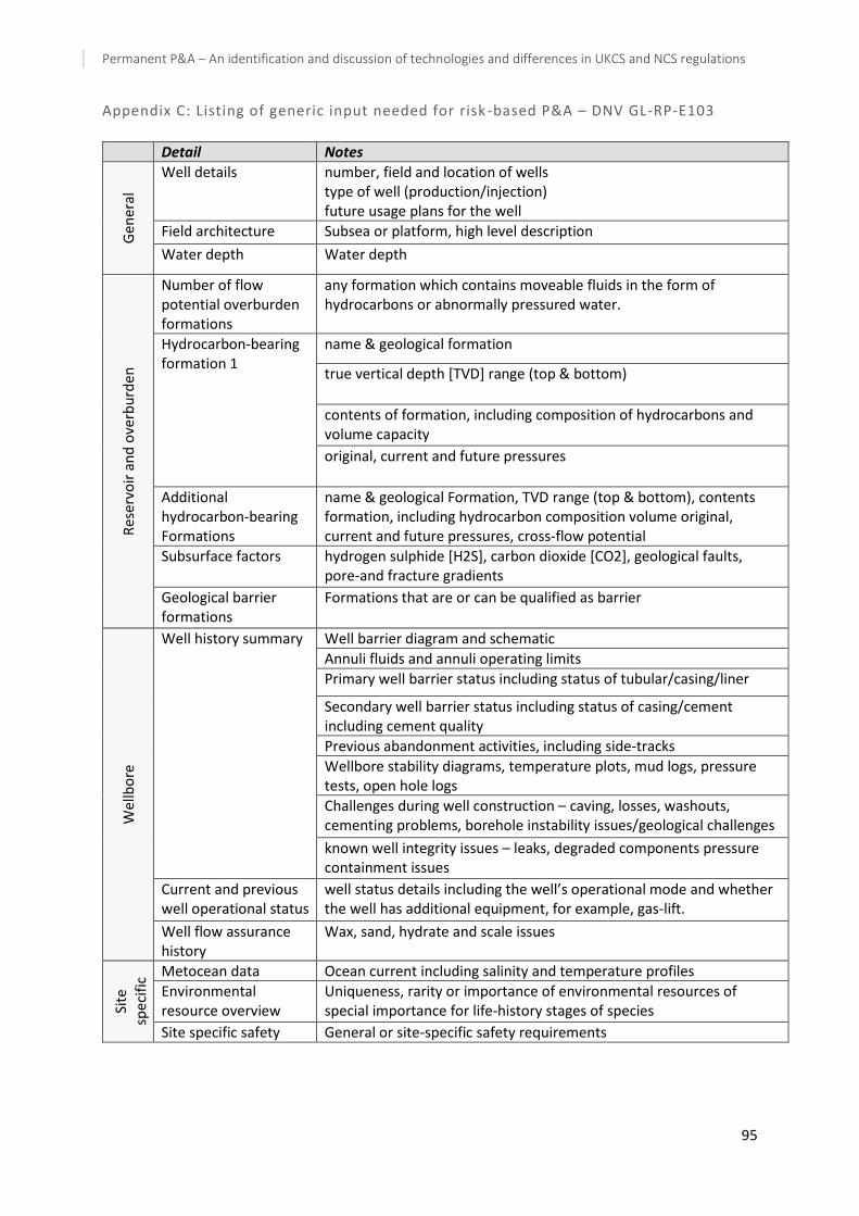
Permanent P&A – An identification and discussion of technologies and differences in UKCS and NCS regulations
95
Appendix C: Listing of generic input needed for risk -based P&A – DNV GL-RP-E103
Detail Notes
Gen
eral
Well details number, field and location of wells type of well (production/injection) future usage plans for the well
Field architecture Subsea or platform, high level description
Water depth Water depth
Res
erv
oir
an
d o
verb
urd
en
Number of flow potential overburden formations
any formation which contains moveable fluids in the form of hydrocarbons or abnormally pressured water.
Hydrocarbon-bearing formation 1
name & geological formation
true vertical depth [TVD] range (top & bottom)
contents of formation, including composition of hydrocarbons and volume capacity
original, current and future pressures
Additional hydrocarbon-bearing Formations
name & geological Formation, TVD range (top & bottom), contents formation, including hydrocarbon composition volume original, current and future pressures, cross-flow potential
Subsurface factors hydrogen sulphide [H2S], carbon dioxide [CO2], geological faults, pore-and fracture gradients
Geological barrier formations
Formations that are or can be qualified as barrier
Wel
lbo
re
Well history summary Well barrier diagram and schematic
Annuli fluids and annuli operating limits
Primary well barrier status including status of tubular/casing/liner
Secondary well barrier status including status of casing/cement including cement quality
Previous abandonment activities, including side-tracks
Wellbore stability diagrams, temperature plots, mud logs, pressure tests, open hole logs
Challenges during well construction – caving, losses, washouts, cementing problems, borehole instability issues/geological challenges
known well integrity issues – leaks, degraded components pressure containment issues
Current and previous well operational status
well status details including the well’s operational mode and whether the well has additional equipment, for example, gas-lift.
Well flow assurance history
Wax, sand, hydrate and scale issues
Site
sp
ecif
ic Metocean data Ocean current including salinity and temperature profiles
Environmental resource overview
Uniqueness, rarity or importance of environmental resources of special importance for life-history stages of species
Site specific safety General or site-specific safety requirements

Permanent P&A – An identification and discussion of technologies and differences in UKCS and NCS regulations
96
Appendix D: Generic well barrier failure modes for P&A wells – DNV GL-RP-E103
Potential failure mode
Potential cause mechanism Risk management strategy
Ma
inb
ore
Insufficient barrier length in mainbore
— low top of barrier — barrier slippage — density miscalculation
include functional barrier length assessments into quantitative models
Barrier function degraded in mainbore
— incorrect barrier density — operational issues — permeable barrier — high barrier shrinkage leads to increased porosity and stresses that may cause a microannulus to form
perform sensitivity studies as to the flow potential through and around these barriers
Ca
sin
g
Corrosion of casing — well fluids exposure or long-term exposure
perform sensitivity studies as to the flow potential through and around these barriers Include formation aspects and time perspectives
Yielding of casing due to pressure in well
— well loading over time including geological forces — formation loads
An
nu
lus
Insufficient barrier length in annulus
— slippage due to inadequate density or losses — not able to perform squeeze job
include functional barrier length assessments into quantitative models with sensitivity studies
Degradation of annulus barrier
— channelling/lack of bonding — CO2 corrosion — H2S corrosion — magnesium chloride degradation — thermal cracking and/or de-bonding (microannulus) due to Joule-Thomson effect during injection into, e.g., depleted gas reservoir — pre-existing channels — pre-existing micro-annulus
perform sensitivity studies as to the flow potential through and around these barriers
Contamination of annulus barrier
— poor mud and filter cake removal leaves a route for hydrocarbons to flow up the annulus — high barrier shrinkage leads to increased porosity and stresses that may cause a microannulus to form
Form
atio
n
Overpressure of formation
— build-up of pressure over time — injection nearby
evaluate the formation characteristics, the need for crossflow prevention and natural leakage/seepage
Fluid exposure — degradation effects over time
Geological barrier formation
— potential to use formations as an additional well barrier, if possible
identify if compacting formations or aquifers can be used as permanent barriers.


