53
Permeable Pavements in Cold Climates Peter T. Weiss, Valparaiso University John Gulliver, UMN Masoud Kayhanian, UC-Davis Lev Khazanovich, Univ. of Pittsburgh 2017 INAFSM Annual Conference
Permeable Pavements in Cold Climates
Peter T. Weiss, Valparaiso University
John Gulliver, UMNMasoud Kayhanian, UC-Davis
Lev Khazanovich, Univ. of Pittsburgh
2017 INAFSM Annual Conference

Outline
• Introduction and background
• Design methods
• Summary of performance & maintenance
• Case Studies– Paired Intersection Study (Minnesota)
– Porous Asphalt Study (New Hampshire)
– Woodbridge Neighborhood (Minnesota)
– Experiences in Colorado
• Summary and Conclusions

A sign at a park in Massachusetts.Image source: MAAPA
Porous pavements developed as early as the 1930s

Full Depth Permeable Pavement
• Water infiltrates through permeable pavement surface and other layers
• Stored in gravel layer (~40% voids)
• Water infiltrates into soil or is collected by drain tile

Benefits PermeablePavement
• Volume reduction
• Improved water quality
• Hydroplaning resistance
• Spray reduction
– Increased visibility
• Smoother ride
• Noise reduction
• Less salt required
Impermeable pavement
Permeable Pavement
Images source: Barrett 2008

Types of Permeable Pavement• Porous Asphalt
• Pervious Concrete
• Permeable Pavers
• Permeable Articulated Concrete Blocks
NAPA
ICPI SDRMCA
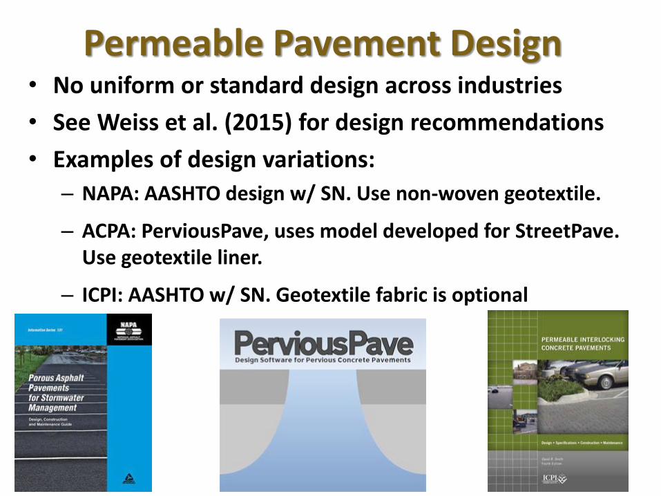
• No uniform or standard design across industries
• See Weiss et al. (2015) for design recommendations
• Examples of design variations:
– NAPA: AASHTO design w/ SN. Use non-woven geotextile.
– ACPA: PerviousPave, uses model developed for StreetPave. Use geotextile liner.
– ICPI: AASHTO w/ SN. Geotextile fabric is optional
Permeable Pavement Design

Keys for Success
• Proper Construction
–Mix design
– Compaction
– Void ratio
– Curing
• Proper and regular maintenance
Photo courtesy of M. Maloney, Shoreview, MN

Summary of Hydraulic Performance
• Surface infiltration rates decrease but are not rate limiting
• Method needed to determine permeability of sub-base before design
• Geotextile fabrics can reduce/eliminate infiltration
• Infiltration rates are maintained through winter
Photo http://ih.constantcontact.com/
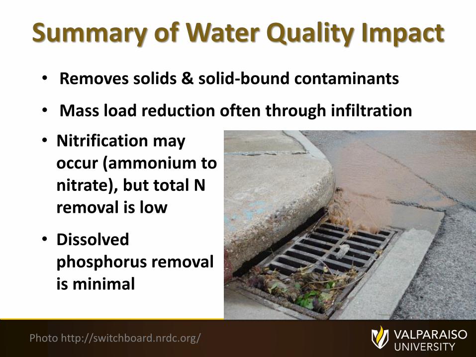
Summary of Water Quality Impact
• Removes solids & solid-bound contaminants
• Mass load reduction often through infiltration
Photo http://switchboard.nrdc.org/
• Nitrification may occur (ammonium to nitrate), but total N removal is low
• Dissolved phosphorus removal is minimal

Summary of Maintenance• Surface cleaning is effective but variable
• Particle removal (top ¼ inch) is major issue
• Pressure washing (45o ) and/or vacuuming with regenerative air sweepers is most effective
• Brushes can push material farther into voids
• Clean multiple times per year
Vacuum Regenerative Air
Images: Elginsweeper.com

Impact of Vacuuming
Permeable articulated concrete blocks/mats before (A) and after (B) cleaning with a Vac Head.
A B
(Photo courtesy of University of Louisville and D. Buch, PaveDrain, LLC).

Summary of Maintenance
• Major cause of clogging is reduction of surface pavement void space:
– Heavy loads
– Particles
– Lack of maintenance
• No standard to measure or evaluate clogging1
3cm
5cm
1% Ks
100% Ks
3% Ks
100% Ks
5% Ks
100% Ks
0 0.1 0.2 0.3 0.4
Porosity
120
80
40
0
Dep
th (
mm
)
Average porosity of 0.22
Actual scanning porosity of 3yr old OGPCC core sample
Projected porosity without maintenanceafter further use
4 yr
5 yr
10 yr
Clogged zone
Projected clogged zone after 5-10 yrs
Open voids
13
cm
5cm
1% Ks
100% Ks
3% Ks
100% Ks
5% Ks
100% Ks
0 0.1 0.2 0.3 0.4
Porosity
120
80
40
0
Dep
th (
mm
)
Average porosity of 0.22
Actual scanning porosity of 3yr old OGPCC core sample
Projected porosity without maintenanceafter further use
4 yr
5 yr
10 yr
Clogged zone
Projected clogged zone after 5-10 yrs
Partially clogged voids

Porous Asphalt Paired Intersections – Robbinsdale, MN
Constructed 2009-2010
Construction in September 2010 (Wenck 2014)
• Objective was to evaluate potential salt load reduction on porous asphalt pavements
• Also durability, maintenance, and water quality

• TMDL study for Shingle Creek, MN: Reduce Cl by 81%
• Two porous asphalt pavement intersection constructed: 1) Sand sub-base, 2) Clay sub-base
• Designed for 2-yr storm
• The porous asphalt sections were not salted during the winter
• Conventional asphalt sections were salted
Paired Intersection Study
(thenewsherald.com)

6” drain tile
Geotextile
4” Asphalt
Max 2” choker course (0.5” crushed stone)
Paired Intersection Study
12” Reservoir Layer (1.5”-2.5” stone)
K
Porous Asphalt Cross-Section (Wenck 2014)

• Porous asphalt sections: ~150 feet long by ~28 feet wide (4200 square feet)
• Cost: Site 1 was $42,670
Site 2 it was $32,200.
• Site 1 construction was negotiated as part of a change order. Site 2 the contract was awarded to the low bidder.
Paired Intersection Study

• Winter reservoir temperatures warmer than the pavement temperature
• Reservoir air voids provided insulation
• Insulation minimizes winter freezing and keeps reservoir temperatures cooler in spring
Paired Intersection StudyResults
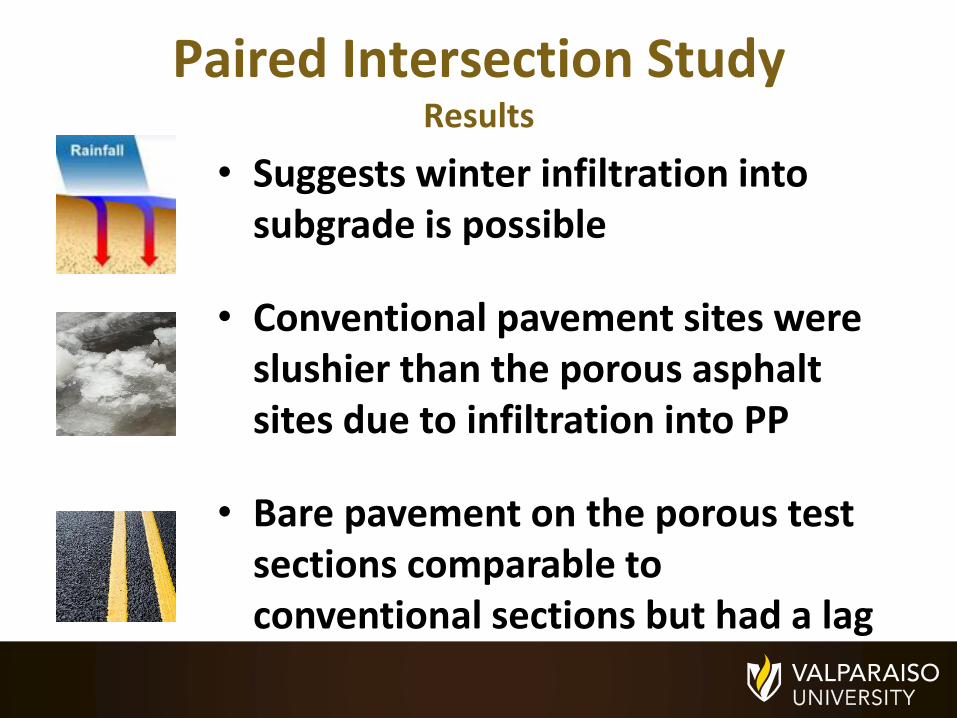
• Suggests winter infiltration into subgrade is possible
• Conventional pavement sites were slushier than the porous asphalt sites due to infiltration into PP
• Bare pavement on the porous test sections comparable to conventional sections but had a lag of 2 to several hours
Paired Intersection StudyResults

Slush gathering and refreezing on the traditional asphalt at Site 1 on January 17, 2010
Paired Intersection Study
Slush free porous asphalt on January 17, 2010
Wenck 2014

Site 1 Test Section looking south
Paired Intersection Study
Wenck 2014

• The unsalted, porous asphalt sections had a similar amount of bare pavement compared to salted, conventional asphalt sections
• The porous pavement over sand subgrade was more effective for ice control compared to the porous pavement on clay subgrade,
– porous asphalt on sand can infiltrate all or most of the runoff
– On clay, frequent overflows were observed
• Porous asphalt sections have been durable without any special snow plow equipment or adjustments
Paired Intersection StudyLessons Learned

• Effective maintenance on the porous asphalt sections appears to be vacuuming twice per year and patching with traditional asphalt, as necessary
• Porous asphalt intersections have potential as an ice-control management practice in certain situations
Paired Intersection StudyLessons Learned
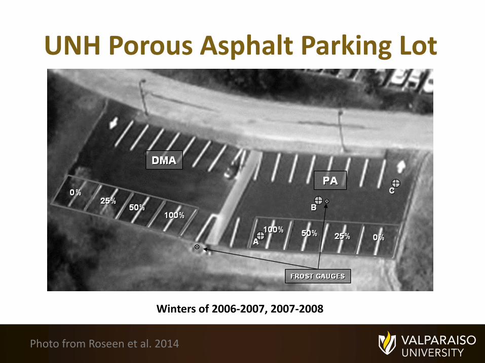
UNH Porous Asphalt Parking Lot
Winters of 2006-2007, 2007-2008
Photo from Roseen et al. 2014

UNH Porous Asphalt Study• Each lot = 5000 ft2
• 4” of porous asphalt
• 18% voids, 5.8% asph.
• Filter Course: K=10-60 ft/day at 95% comp.
• Filter blanket prevents migration of fines
• 21 inch stone reservoir
• Underdrain 12 inches above bottom
Image from Roseen et al. 2014

UNH Porous Asphalt Study
• PA lot received 25% of typical salt load of 3 lb/1000 sf
• DMA received 100% of typical salt load
• Frost penetration deeper on PA (27” vs. 18”)
• PA lot thawed ~30 days before DMA
• 25% of runoff infiltrated in PA (Type C soils)
a) PA at 11:20 AM; b) PA at 1 PM; c) DMA at 11:20 AM; d) DMA at 1 Pm (Roseen et al. 2014)

UNH Porous Asphalt Study
Lots one hour after plowing (-4o C)(Photo: UNHSC)
UNHSC

UNH Porous Asphalt Study• PA exported nitrate;• PA: no impact on TP;• PA reduced TPH
(1970 mg/L to 166 mg/L
Pavement after freezing rain: a) PA, b) DMA(Roseen et al. 2014)
• PA reduced TSS (54 mg/L to 6 mg/L)
• PA mean infiltration rate = 1700 in/hr after 3 yrs & no maintenance

UNH PA Parking Lot Study-Conclusions
• PA with 25% of salt load had same snow/ice cover as DMA lot
• Salt loads could be reduced by 64% with no compromise in safety
• PA froze but maintained high infiltration capacity
• PA had higher skid resistance (for wet, snow, & compacted snow)
• More salt applications may be necessary
• PA particles were found in voids after winter
Roseen et al. 2014. Photo: Heather Lynn Peters

Woodbridge Neighborhood-Shoreview, MN
Pervious Concrete, constructed in 2009. Photo courtesy of M. Maloney
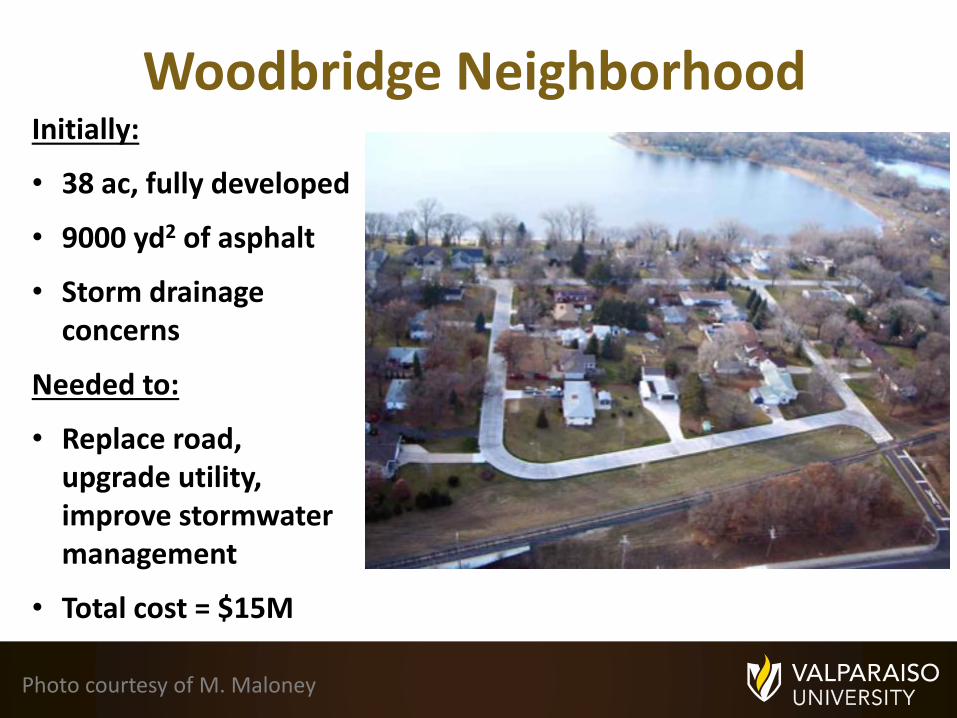
Woodbridge Neighborhood
Photo courtesy of M. Maloney
Initially:
• 38 ac, fully developed
• 9000 yd2 of asphalt
• Storm drainage concerns
Needed to:
• Replace road, upgrade utility, improve stormwater management
• Total cost = $15M

Woodbridge Neighborhood
Project construction. Photo courtesy of M. Maloney
Why PC?• Free draining soils• Advances in mix designs and placement techniques• Same cost as conventional asphalt with storm drains

Woodbridge Neighborhood -Construction
Curing of Pervious Concrete.Photo courtesy of M. Maloney
• 18” crushed rock reservoir• Tri-roller screed for consolidation• Curing fabric used instead of poly sheeting placed
within 1 minute (7 day duration)• Mix Design: 125 PCF, 21% air voids (+/- 3%)• 7” of pervious concrete• 1.5” Railroad ballast, 18-30” thick• $86.30 per SY• Saw cut joints 24-48 hours after pour
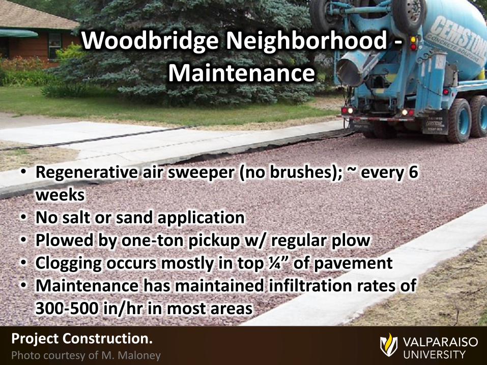
Woodbridge Neighborhood -Maintenance
Project Construction.Photo courtesy of M. Maloney
• Regenerative air sweeper (no brushes); ~ every 6 weeks
• No salt or sand application• Plowed by one-ton pickup w/ regular plow• Clogging occurs mostly in top ¼” of pavement• Maintenance has maintained infiltration rates of
300-500 in/hr in most areas

Lessons Learned
Saw cut joint.Photo courtesy of M. Maloney
• Construction & curing very important
• Saturated curing blankets have been successful
• Saw cut joints have been successful
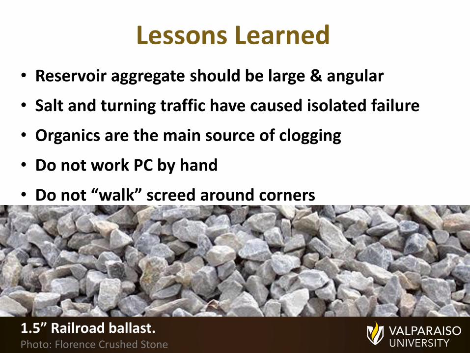
Lessons Learned
1.5” Railroad ballast.Photo: Florence Crushed Stone
• Reservoir aggregate should be large & angular
• Salt and turning traffic have caused isolated failure
• Organics are the main source of clogging
• Do not work PC by hand
• Do not “walk” screed around corners

The Denver (UDFCD) Experience
Denver, Colorado.Photo: PlaneandJane.com

Photo courtesy of K. MacKenzie, UDFCD
• Pervious Concrete
• Installed in 2004
• No info on mix design
• Raveling at joints (some saw cut)
Aurora Wal-Mart Parking Lot

Photo courtesy of K. MacKenzie, UDFCD
• Pervious Concrete
• Installed in 2004
• No info on mix design
• Surface erosion
Denver Safeway Parking Lot

Photo courtesy of K. MacKenzie, UDFCD
• Pervious Concrete
• Installed in 2005
• No info on mix design
• Surface erosion
University Plaza Parking Lot
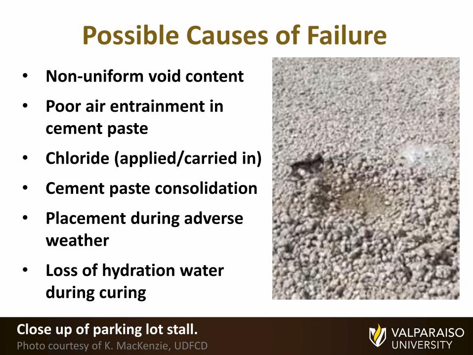
Close up of parking lot stall.Photo courtesy of K. MacKenzie, UDFCD
• Non-uniform void content
• Poor air entrainment in cement paste
• Chloride (applied/carried in)
• Cement paste consolidation
• Placement during adverse weather
• Loss of hydration water during curing
Possible Causes of Failure

Photo courtesy of K. MacKenzie, UDFCD
• Pervious Concrete
• Installed in 2009
• Mix design followed new requirements
• PC use in Denver suspended
National Renewable Energy Lab Parking Lot
2011

Parking lot after light rain.Photo courtesy of K. MacKenzie, UDFCD
• Porous Asphalt
• Installed in 2008
• Surface infiltration < 20 in/hr
• Intensive maintenance was ineffective
Denver Waste Management Building

Parking lot after snowfall.Photo courtesy of K. MacKenzie, UDFCD
• Cores revealed proper construction (17% voids, proper PSD, asphalt content, etc.)
• More than half of other PA sites have infiltration < 20 in/hr
• UDFCD does not recommend use of PA
Denver Waste Management Building

Conclusions• Permeable pavements can result in less winter salt
application
• Permeable pavements can reduce runoff volume and improve water quality (with other benefits)
• Permeable pavements are more expensive to construct
• Construction & maintenance are critical to success

Conclusions (Cont’d)
• Maintenance: pressure washing and/or vacuuming
• Permeable pavements can withstand harsh winters
• Permeable pavements can maintain infiltration rates throughout the winter

Acknowledgements
Funding Agency:
Project funded by the Local Road Research Board and the Minnesota Department of Transportation
Collaborators:
John S. Gulliver, University of MinnesotaMasoud Kayhanian, University of California-DavisLev Khazanovich, University of Pittsburgh

Questions?
Questions?
Thank you for your attention!
[email protected] Photo: http://itcontrolsfreak.files.wordpress.com/2012/11/rain1.jpg

References (page 1)
ACI (American Concrete Institute). 2010. Report on Pervious Concrete. ACI, Farmington Hills, MI, USA. ACI 522R-10.
Barrett, M.E. 2008. Effects of a Permeable Friction Course on Highway Runoff. Journal of Irrigation and Drainage Engineering, 134(5):646-651.
CRMCA (Colorado Ready Mixed Concrete Association). 2009. Specifier’s guide for pervious concrete pavement design. CRMCA, Centenial, CO, USA.
Jones D., Harvey J., Li H., Wang T., Wu R. and Campbell B. (2010). Laboratory testing and Modeling for Structural Performance of Fully Permeable Pavements under Heavy Traffic. Report number CTSW-RT-10-249.04 prepared for California Department of Transportation, Sacramento, California.
Li, H., Jones, D., Harvey, J. 2012. Development of mechanistic-empirical design procedure for fully permeable pavement under heavy traffic. Transportation Research Record, 2305:83-94.
NAPA (National Asphalt Pavement Association). 2008. Porous asphalt pavements for stormwater management, Design, Construction and maintenance guide. Information Series 131, NAPA, Lanham, MD, USA.

References (page 2)
Partl, M.N., Momm, F., Bariani, B. 2003. Study of the aggregate for the pervious asphalt concrete performance testing and evaluation of bituminous materials. Proceedings of the 6th International RILEM Symposium, 2003/04/14-2003/04/16. Zurich, Switzerland. pp. 237-43.
Roseen, R.M., Ballestero, T.P., Houle, K.M., Heath, D., Houle, J.J. 2014. Assessment of winter maintenance of porous asphalt and its function for chloride source control, Journal of Transportation Engineering, 140(2): 04013007, 1-8.
UNHSC (University of New Hampshire Stormwater Center). 2009. UNHSC Design specifications for porous asphalt pavement and infiltration beds. University of New Hampshire, Durham, NH, USA.
Weiss, P.T., Kayhanian, M., Khazanovich, L., and J.S. Gulliver, "Permeable Pavements in Cold Climates: State of the Art and Cold Climate Case Studies," Report #: MN/RC 2015-30, Minnesota Department of Transportation, St. Paul, MN, 2015.
Wenck Associates, Inc. 2014. Porous pavement paired intersection study, prepared for the Shingle Creek Watershed Management Commission, City of Robbinsdale, MN, and the Minnesota Pollution Control Agency, Maple Plain, MN, USA.

1. Particle size distribution & binder type are the 2 most important factors in mix selection (Jones et al. 2010; Li et al. 2012)
2. Void ratios of 25% & infiltration rates of > 7 cm/s possible by optimizing aggregate (Partl 2003)
3. Typical air voids are 16 – 20% (NAPA 2008)
4. Depth of aggregate bed to be 65% of frost depth (UNHSC
2009)
5. Typical aggregate gradations/specs given in reports (NAPA
2008)
Porous Asphalt Design Recommendations
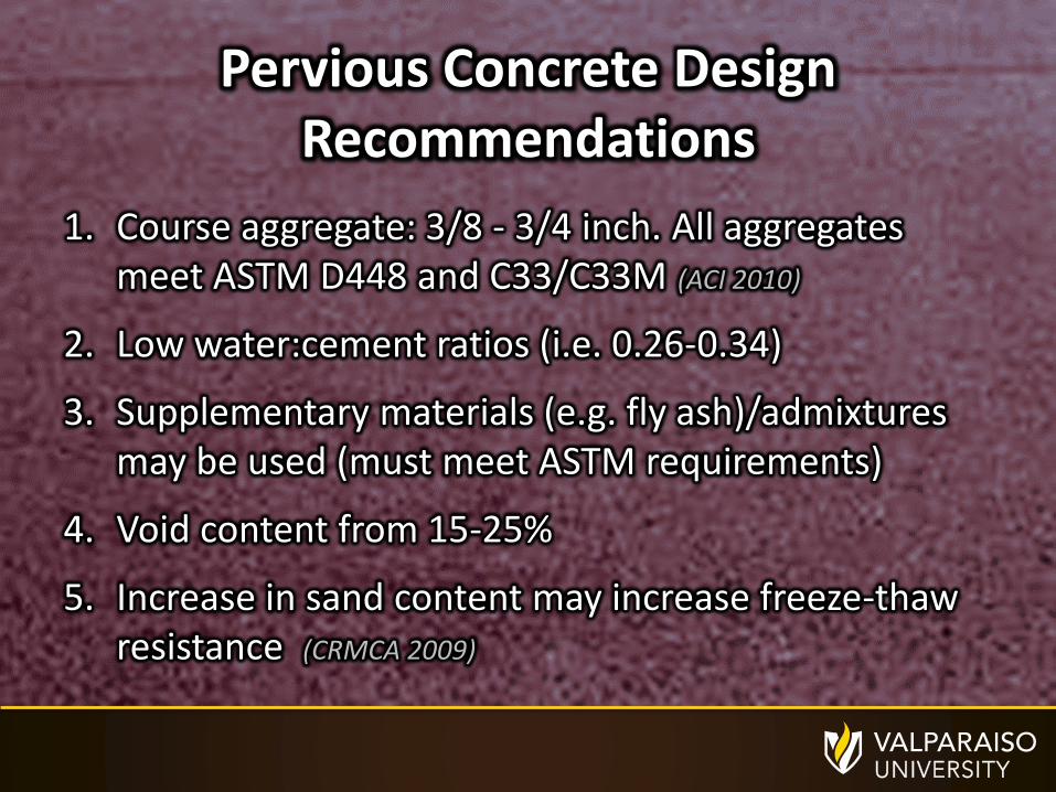
1. Course aggregate: 3/8 - 3/4 inch. All aggregates meet ASTM D448 and C33/C33M (ACI 2010)
2. Low water:cement ratios (i.e. 0.26-0.34)
3. Supplementary materials (e.g. fly ash)/admixtures may be used (must meet ASTM requirements)
4. Void content from 15-25%
5. Increase in sand content may increase freeze-thaw resistance (CRMCA 2009)
Pervious Concrete Design Recommendations

1. Open-graded bases: <2% fines, density: 95-120 lb/ft3, porosities >30%
2. All stone & aggregate: >=90% fractured faces and a minimum Los Angeles abrasion value of less than 40
3. Base and sub-base: porosity >= 32%, CBR >= 80%
Permeable Paver Design Recommendations


