16
Persona ® The Personalized Knee Trabecular Metal ™ Tibia Surgical Technique
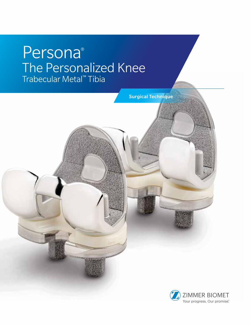
Persona® The Personalized KneeTrabecular Metal™ Tibia
Surgical Technique

Table of Contents
Resect the Tibia......................................................................................................... 4
Size and Finish the Tibia ........................................................................................... 4
Trial Fit ....................................................................................................................... 6
Component Implantation ......................................................................................... 7 Inserter/Implant Assembly .................................................................................. 7 Cementless Implantation Option ......................................................................... 8 Cemented Implantation Option ........................................................................... 9 Implant the Femoral Component ....................................................................... 10 Implant the Bearing ........................................................................................... 11

2 | Persona Trabecular Metal Tibia Surgical Technique
Symbols
Symbols have been established for the following:
• Left
• Right
• Varus/Valgus
• Medial/Lateral
• Standard
• Do not implant - Not for implant
• Lock
• Unlock
• Anterior Referencing
• Do not impact
• Cemented
• Steamed
• Inset Only
Introduction
The Persona® Trabecular Metal™ Tibia unites stable fixation with a modular design enabling use with compatible cruciate retaining, medial congruent, ultracongruent, and posterior stabilized bearing implants. The modularity also allows replacement of just the bearing, if necessary, when revising a well-fixed tibial tray.
A wide variety of component sizes, shapes, and constraint options support proper component fit and soft tissue balancing. The surgeon can choose a midvastus approach, a subvastus approach, or a parapatellar medial arthrotomy.
See the Persona Knee Surgical Technique for the available implant constraint options.
To achieve successful porous tibial component arthroplasty, please note the technique tips throughout the surgical technique and those listed below.
- Precise, flat bone cuts are essential to maximize the Trabecular Metal Material contact with the resected bone
- Ensure that peg holes are drilled to their full depth and free of debris
- Guide the impaction with the inserter, both in the sagital and the coronal planes, to ensure the inferior surface of the implant remains parallel to the resected tibial surface through visual checks during impaction
Magnetic Usage
Warning: Some instruments in the Persona System contain magnets. All Persona Magnetic Instruments should be kept at a safe distance from a patient’s active implantable medical device(s) (i.e. pacemaker). These types of devices may be adversely affected by magnets. Instruments containing magnets should be kept on an appropriate table or stand when not in use at the surgical site.
Lock
Medial/Lateral
M/L
Left
Do not impact
Unlock
Standard
Std
Right
Cemented
Inset Only
Do not implant - Not for implant
Varus/Valgus
Stemmed
Anterior Referencing
3 | Persona Trabecular Metal Tibia Surgical Technique
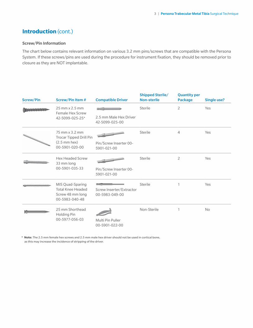
* Note: The 2.5 mm female hex screws and 2.5 mm male hex driver should not be used in cortical bone,
as this may increase the incidence of stripping of the driver.
Screw/Pin Information
The chart below contains relevant information on various 3.2 mm pins/screws that are compatible with the Persona System. If these screws/pins are used during the procedure for instrument fixation, they should be removed prior to closure as they are NOT implantable.
Screw/Pin Screw/Pin Item # Compatible DriverShipped Sterile/Non-sterile
Quantity per Package Single use?
25 mm x 2.5 mm Female Hex Screw 42-5099-025-25* 2.5 mm Male Hex Driver
42-5099-025-00
Sterile 2 Yes
75 mm x 3.2 mm Trocar Tipped Drill Pin (2.5 mm hex) 00-5901-020-00
Pin/Screw Inserter 00-5901-021-00
Sterile 4 Yes
Hex Headed Screw 33 mm long 00-5901-035-33 Pin/Screw Inserter 00-
5901-021-00
Sterile 2 Yes
MIS Quad-Sparing Total Knee Headed Screw 48 mm long 00-5983-040-48
Screw Inserter/Extractor00-5983-049-00
Sterile 1 Yes
25 mm Shorthead Holding Pin 00-5977-056-03 Multi Pin Puller
00-5901-022-00
Non-Sterile 1 No
Introduction (cont.)

4 | Persona Trabecular Metal Tibia Surgical Technique
Size and Finish the TibiaOnce tibial osteophytes have been thoroughly removed, select the appropriate Trabecular Metal Right or Left Sizing Plate (sizes A–J) that provides the desired tibial coverage, without overhang at any location on the resected tibia. Attach the sizing plate handle to the sizing plate (Figure 1).
The recommended tibial rotational alignment is within 5° of the axis created by the medial 1/3 of the tibial tubercle and the PCL attachment point. The engraved line on the sizing plate can be used to aid in establishing the desired tibial rotation (Figure 2).
Rotate the sizing plate to attain the desired tibial rotational alignment. The notch in the lateral periphery of the sizing plate provides an aid to establish proper position with respect to the lateral border of the tibia without medialization of the sizing plate.
Technique Tip: Check the flatness of the tibial cut surface with the selected sizing plate. Attempt to rock the plate, A/P and M/L. A rocking motion indicates a cut that is not flat. A flat cut is required to properly seat and ensure proper contact between the implant and tibial cut surface.
If a flat cut can not be achieved, then the Persona Trabecular Metal Tibial Tray should be cemented to the proximal tibia.
Resect the TibiaRefer to the “Resect Proximal Tibial” section of the Persona Knee Surgical Technique (97-5026-001-00) for additional resection instructions.
Additional care must be taken when implanting porous components. The flatness of the proximal tibial resection is critical to ensuring adequate contact between the Persona Trabecular Metal Tibial Implant and the bone. Evaluate the flatness of the proximal tibial resection prior to drilling the hexagonal pegs.
Technique Tip: Areas where the bone transitions from high to low density, such as from cortical to cancellous bone, may cause the saw blade to skive and result in an inconsistent cut. Use caution when resecting in these regions and operate the saw at high speed but advance the saw slowly to ensure a consistent cut.
Before securing the sizing plate to the bone, evaluate the bone quality. If the bone is of poor quality, the Persona Trabecular Metal Tibial Tray should be cemented to the proximal tibia.
Technique Tip: Bone quality may be analyzed by palpating the bone in the intercondylar region of the tibial plateau. If the bone can be indented with light finger pressure, then the Persona Trabecular Metal Tibial Tray should be cemented to the proximal tibia.
Do not use the short headed holding pins in these holes
Figure 3Figure 1 Figure 2
Use the medial and lateral holes near the PCL cutout for fixation
1. Depress
3. Release2. Insert

5 | Persona Trabecular Metal Tibia Surgical Technique
Size and Finish the Tibia (cont.)When the desired position has been attained, secure the sizing plate by placing 25 mm x 3.2 mm (2.5 mm female hex) screws or 25 mm x 3.2 mm short head holding pins in the medial and lateral holes near the PCL cutout of the sizing plate (Figures 2 and 3). The remaining adjunct fixation holes shown on the surface of the sizing plate can be used if necessary.
Use only the female hex head screws in the holes designated with a caution symbol. Ensure that the sizing plate remains in the proper position when securing it to the bone.
Technique Tip: Do not impact, lever, or pry the sizing plate handle; this instrument is designed for alignment purposes only. Use the alignment rod in the hole or slot in the sizing plate handle to verify proper tibial plate varus/valgus alignment. (See Appendix A of the Persona Knee Surgical Technique (97-5026-001-00) for correcting varus/valgus resections).
Technique Tip: If using a screw through the anterior medial hole on the periphery of the sizing plate, ensure that the sizing plate remains in the desired position and does not lift off posteriorly.
Ensure that the sizing plate remains in the proper position when securing it to the bone. Once desired alignment has been verified with the alignment rod, remove the sizing plate handle from the sizing plate (Figure 4).
Persona Trabecular Metal Sizing Plate Size F Left 42-5398-075-11
Persona Tibial Sizing Plate Handle 42-5399-017-00
25 mm x 2.5 mm Female Hex Head Screw 42-5099-025-25
2.5 mm Male Hex Driver 42-5099-025-00
25mm X 3.2 mm Short Head Holding Pin00-5977-056-03
Alignment Rod with Coupler 00-5785-080-00
Figure 4
6 | Persona Trabecular Metal Tibia Surgical Technique
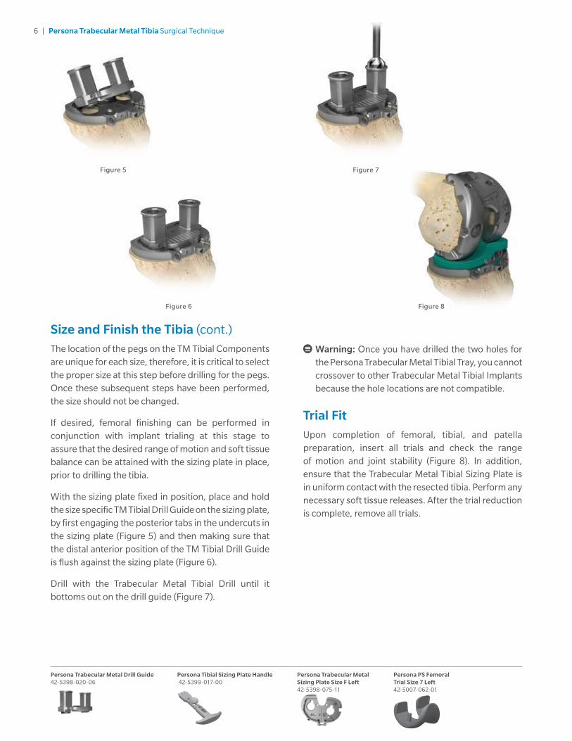
Figure 7
Figure 8Figure 6
Warning: Once you have drilled the two holes for the Persona Trabecular Metal Tibial Tray, you cannot crossover to other Trabecular Metal Tibial Implants because the hole locations are not compatible.
Trial FitUpon completion of femoral, tibial, and patella preparation, insert all trials and check the range of motion and joint stability (Figure 8). In addition, ensure that the Trabecular Metal Tibial Sizing Plate is in uniform contact with the resected tibia. Perform any necessary soft tissue releases. After the trial reduction is complete, remove all trials.
Size and Finish the Tibia (cont.)
The location of the pegs on the TM Tibial Components are unique for each size, therefore, it is critical to select the proper size at this step before drilling for the pegs. Once these subsequent steps have been performed, the size should not be changed.
If desired, femoral finishing can be performed in conjunction with implant trialing at this stage to assure that the desired range of motion and soft tissue balance can be attained with the sizing plate in place, prior to drilling the tibia.
With the sizing plate fixed in position, place and hold the size specific TM Tibial Drill Guide on the sizing plate, by first engaging the posterior tabs in the undercuts in the sizing plate (Figure 5) and then making sure that the distal anterior position of the TM Tibial Drill Guide is flush against the sizing plate (Figure 6).
Drill with the Trabecular Metal Tibial Drill until it bottoms out on the drill guide (Figure 7).
Persona Trabecular Metal Drill Guide 42-5398-020-06
Persona Tibial Sizing Plate Handle 42-5399-017-00
Persona Trabecular Metal Sizing Plate Size F Left 42-5398-075-11
Persona PS Femoral Trial Size 7 Left 42-5007-062-01
Figure 5

7 | Persona Trabecular Metal Tibia Surgical Technique
Figure 9 Figure 10a Figure 10b
Persona Trabecular Metal Drill Guide 42-5398-020-06
Persona Tibial Sizing Plate Handle 42-5399-017-00
Persona Trabecular Metal Sizing Plate Size F Left 42-5398-075-11
Persona PS Femoral Trial Size 7 Left 42-5007-062-01
Persona Trabecular Metal Tibial Tray Size F Left 42-5300-075-01
Persona Locking Tibia Inserter Size E-F 42-5398-092-05
Component ImplantationAfter the implants have been chosen, make a final check to ensure that the size chosen for the femoral, tibial, and bearings are compatible.
Inserter/Implant Assembly
Depress the lever of the tibial inserter to extend the metal distal tab (Figure 9). Insert the tab into the implant’s dovetails on the central portion of the tibial implant. Slide the tibial inserter posteriorly until the tab engages the dovetails (Figure 10a). Release the lever to secure the tibial inserter to the tibial implant. Ensure the tibial inserter is seated flush to the proximal surface of the tibial implant (Figure 10b).
The Persona Trabecular Metal Tibial Tray may be implanted with or without bone cement (cemented or cementless options).
Posterior Anterior

8 | Persona Trabecular Metal Tibia Surgical Technique
Component Implantation (cont.)
Cementless Implantation Option
Prior to implantation of a Persona Trabecular Metal Tibial Tray, the resected tibial bone surface must be flat and free of bone debris and fragments.
Sublux the tibia anteriorly to allow adequate clearance to insert the tibial implant into the prepared bone.
Keep the implant clean and free of debris prior to implanting. The two hexagonal shaped Trabecular Metal Pegs must be axially aligned with the prepared holes in the proximal tibia. Slowly impact the tibial implant ensuring that the inferior surface of the implant and proximal tibia are parallel with respect to each other (Figures 11a and 11b). Continue impaction until the tibial implant is fully seated. Perform a visual check to ensure the tibial implant is fully seated on the proximal tibia cut surface. To release the inserter from the implant, depress the lever on the tibial inserter. The handle will move in a superior direction away from the tibial implant (Figure 12). Tilt the handle posteriorly to disengage the distal tab of the inserter from the plate (Figure 13). After the inserter has been removed, the inserter can be used as a non-locking inserter if desired.
Warning: Do not impact the release lever on the inserter.
Figure 11a Figure 12 Figure 13 Figure 14Figure 11b
Warning: If the bone density varies across the tibial plateau, one peg may be easier to seat than the other. Uneven impaction may compromise initial fixation.
Warning: Levering the tibial inserter while engaged with the tibial tray may compromise the initial fixation.
Note: After impaction, it is important to ensure that the tibial implant is in uniform contact with the resected tibia, and that no gaps are present between the implant and bone (Figure 14). Fixation, support and/or stability may be insufficient if gaps are present between the implant and bone.
Note: The patient's bone quality must be assessed for density and quality to ensure adequate support and fixation of the tibial implant. Bone stock of insufficient quality and/or density may not be capable of adequately supporting the component. If the bone stock is of questionable quality or density, the tibial implant should be cemented to the proximal tibia.
Persona Trabecular Metal Tibial Tray Size F Left 42-5300-075-01
Persona Locking Tibia Inserter Size E-F 42-5398-092-05
9 | Persona Trabecular Metal Tibia Surgical Technique
Sublux the tibia anteriorly to allow adequate clearance to insert the tibial implant into the prepared bone. Do not apply substances other than bone cement to the tibial implant (i.e. do not dip implant into antibiotics or other substances). Keep the implant clean and free of debris prior to cementing. Position the tibial plate onto the tibia and use the tibial inserter to impact it until fully seated.
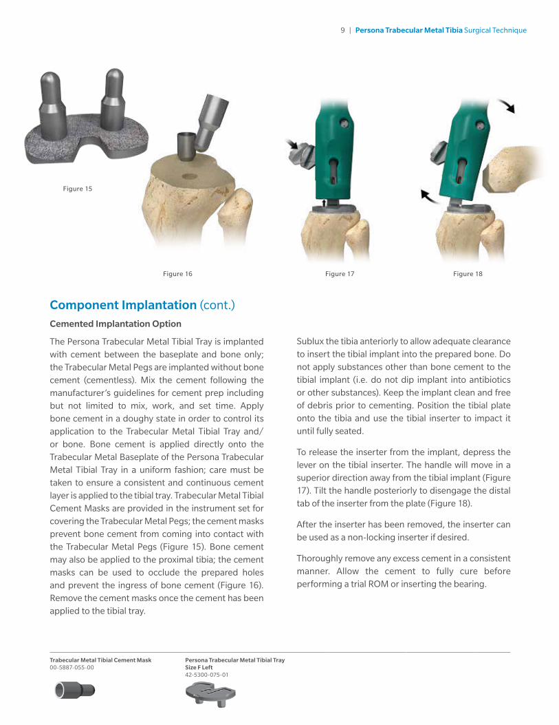
To release the inserter from the implant, depress the lever on the tibial inserter. The handle will move in a superior direction away from the tibial implant (Figure 17). Tilt the handle posteriorly to disengage the distal tab of the inserter from the plate (Figure 18).
After the inserter has been removed, the inserter can be used as a non-locking inserter if desired.
Thoroughly remove any excess cement in a consistent manner. Allow the cement to fully cure before performing a trial ROM or inserting the bearing.
Component Implantation (cont.)
Cemented Implantation Option
The Persona Trabecular Metal Tibial Tray is implanted with cement between the baseplate and bone only; the Trabecular Metal Pegs are implanted without bone cement (cementless). Mix the cement following the manufacturer’s guidelines for cement prep including but not limited to mix, work, and set time. Apply bone cement in a doughy state in order to control its application to the Trabecular Metal Tibial Tray and/or bone. Bone cement is applied directly onto the Trabecular Metal Baseplate of the Persona Trabecular Metal Tibial Tray in a uniform fashion; care must be taken to ensure a consistent and continuous cement layer is applied to the tibial tray. Trabecular Metal Tibial Cement Masks are provided in the instrument set for covering the Trabecular Metal Pegs; the cement masks prevent bone cement from coming into contact with the Trabecular Metal Pegs (Figure 15). Bone cement may also be applied to the proximal tibia; the cement masks can be used to occlude the prepared holes and prevent the ingress of bone cement (Figure 16). Remove the cement masks once the cement has been applied to the tibial tray.
Trabecular Metal Tibial Cement Mask 00-5887-055-00
Persona Trabecular Metal Tibial Tray Size F Left 42-5300-075-01
Figure 15
Figure 17 Figure 18Figure 16
10 | Persona Trabecular Metal Tibia Surgical Technique
Figure 19
Component Implantation (cont.)
Implant the Femoral Component
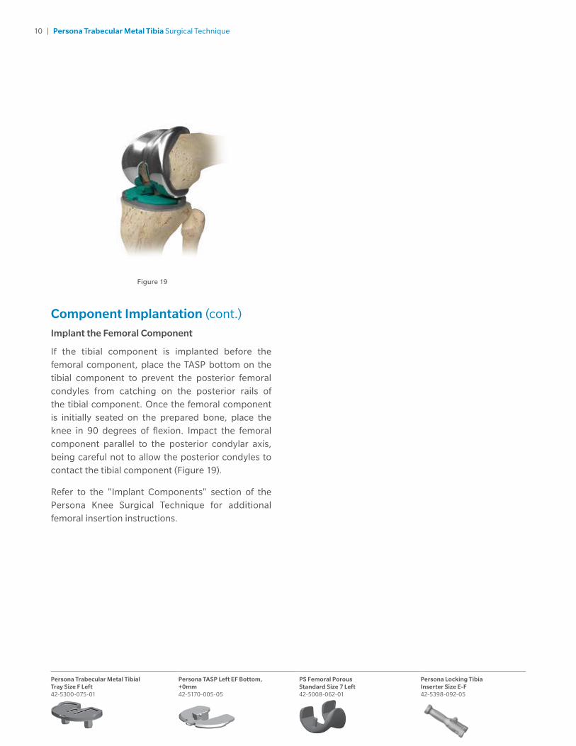
If the tibial component is implanted before the femoral component, place the TASP bottom on the tibial component to prevent the posterior femoral condyles from catching on the posterior rails of the tibial component. Once the femoral component is initially seated on the prepared bone, place the knee in 90 degrees of flexion. Impact the femoral component parallel to the posterior condylar axis, being careful not to allow the posterior condyles to contact the tibial component (Figure 19).
Refer to the "Implant Components" section of the Persona Knee Surgical Technique for additional femoral insertion instructions.
Persona Trabecular Metal Tibial Tray Size F Left 42-5300-075-01
Persona TASP Left EF Bottom, +0mm 42-5170-005-05
PS Femoral Porous Standard Size 7 Left 42-5008-062-01
Persona Locking Tibia Inserter Size E-F 42-5398-092-05

11 | Persona Trabecular Metal Tibia Surgical Technique
Persona Trabecular Metal Tibial Tray Size F Left 42-5300-075-01
Persona TASP Left EF Bottom, +0mm 42-5170-005-05
PS Femoral Porous Standard Size 7 Left 42-5008-062-01
Persona Locking Tibia Inserter Size E-F 42-5398-092-05
Persona Articular Surface Inserter 42-5299-001-00
Component Implantation (cont.)
Implant the Bearing
The bearing inserter applies both downward and rearward forces to aid in the insertion of the bearing onto the tibial base plate. Choose the correct tibia bearing based on size, side, constraint, and thickness as determined by the trial range of motion.
Place the bearing onto the Persona Trabecular Metal Tibial Tray, apply pressure anterior to posterior to properly engage the tibial component and tibial bearing for final seating. This is necessary to allow the inserter to properly engage the tibial component and tibial bearing for final seating. Steady the surface of the base plate with one hand by applying downward pressure near the posterior cruciate cutout (Figure 20a).
Engage the hook on the bearing inserter with the mating slot in the front of the Persona Trabecular Metal Tibial Tray and close the lever with your index finger.
This locks the inserter to the Persona Trabecular Metal Tibial Tray (Figure 20b). Squeeze the handle of the bearing inserter to seat the bearing (Figure 20c). Open the lever and remove the bearing inserter.
Refer to the “Implant Components” section of the Persona Knee Surgical Technique for additional tibial
bearing insertion instructions and for tibia and femur component compatibility.
Technique Tip: Insert a bearing only once. Never reinsert the same bearing onto a tibial baseplate.
Technique Tip: To help stabilize the Persona Trabecular Metal Tibial Tray, the bearing can be inserted with the knee in extension.
Technique Tip: Engage the lever of the inserter with the tibial baseplate to set the proper alignment for bearing insertion and to avoid levering on the baseplate during the insertion process. Failure to do so may disrupt the implant-to-bone interface.
Warning: Do not lever the bearing inserter proximally while it is engaged with the tibial component as this may compromise the initial fixation.
Technique Tip: When using the Persona Trabecular Metal Tibia Tray, in vivo assembly of the bearing is required. The Persona Locking Tibial Inserter cannot be used to align the pegs to the bone preparation if the bearing is assembled before impaction.
Figure 20a Figure 20b Figure 20c

12 | Persona Trabecular Metal Tibia Surgical Technique
Notes

All content herein is protected by copyright, trademarks and other intellectual property rights, as applicable, owned by or licensed to Zimmer Biomet or its affiliates unless otherwise indicated, and must not be redistributed, duplicated or disclosed, in whole or in part, without the express written consent of Zimmer Biomet.
This material is intended for health care professionals. Distribution to any other recipient is prohibited.
For product information, including indications, contraindications, warnings, precautions, potential adverse effects and patient counseling information, see the package insert and zimmerbiomet.com.
Zimmer Biomet does not practice medicine. This technique was developed in conjunction with a health care professional. This document is intended for surgeons and is not intended for laypersons. Each surgeon should exercise his or her own independent judgment in the diagnosis and treatment of an individual patient, and this information does not purport to replace the comprehensive training surgeons have received. As with all surgical procedures, the technique used in each case will depend on the surgeon’s medical judgment as the best treatment for each patient. Results will vary based on health, weight, activity and other variables. Not all patients are candidates for this product and/or procedure.
Caution: Federal (USA) law restricts this device to sale by or on the order of a surgeon. Rx only.
© 2017 Zimmer Biomet
97-5026-027-00 Rev 5 11/17 MC180758
Legal ManufacturerZimmer, Inc. 1800 West Center Street Warsaw, Indiana 46580 USA
zimmerbiomet.com
CE mark on a surgical technique is not valid unless there is a CE mark on the product label.
0086


![[Guitar Tab] Cacophony - [1987] Speed Metal Symphony(2)](https://static.documents.pub/doc/80x56/54f500c24a7959f82d8b4a8b/guitar-tab-cacophony-1987-speed-metal-symphony2.jpg)


