25

Personalized Air-Conditioning in Electric Vehicles
Seminar Paper
Leon Neiÿkenwirth
Institute of Energy E�ciency and Sustainable Building
Matriculation Number: 3109515
University of Applied Sciences Aachen
Subject Area: Civil Engineering and Applied Mathematics
Course of Studies: Scienti�c Programming
Supervisor:
Prof. Dr. rer. nat. Alexander Voÿ
Henning Metzmacher, M. Sc.
December 15, 2018

Abstract
Combustion engine cars contribute substantially to global CO2 emissions which is amajor factory in climate change. Electric vehicles as an alternative are becoming moreand more popular, however, current issues like decreased driving range still inhibitswidespread use. In addition, an already diminished range is further reduced throughthe vehicle's heating, ventilation and air-conditioning (HVAC) system. In order tominimize the energy consumption of the heating engine personalized heating o�ersa possible solution. The technology focuses on a single person instead of heating orcooling the entire cabin. In this seminar paper. di�erent radiant heaters were put totest with test persons giving feedback regarding the comfort. The heaters were testedseparately with the room being cooled down to 18◦C. Through the feedback from thetest person it was derived that especially infrared lamps provide suitable capabilities interms of providing personal comfort. Energy consumption was reduced to a fraction ofthe energy used by normal air heating engines, making it a great alternative in termsof energy e�ciency as well as thermal comfort.

Contents
1 Introduction 1
2 Literature Review 2
2.1 Thermal Comfort . . . . . . . . . . . . . . . . . . . . . . . . . . . . . . . . . 22.2 Personalized HVAC . . . . . . . . . . . . . . . . . . . . . . . . . . . . . . . . 32.3 Assessment and Feedback Systems . . . . . . . . . . . . . . . . . . . . . . . 42.4 Human Computer Interaction . . . . . . . . . . . . . . . . . . . . . . . . . . 5
3 Methodology 6
3.1 Java-Server . . . . . . . . . . . . . . . . . . . . . . . . . . . . . . . . . . . . 63.2 Actuators . . . . . . . . . . . . . . . . . . . . . . . . . . . . . . . . . . . . . 73.3 Raspberry Pi . . . . . . . . . . . . . . . . . . . . . . . . . . . . . . . . . . . 83.4 Camera Setup . . . . . . . . . . . . . . . . . . . . . . . . . . . . . . . . . . . 93.5 Application . . . . . . . . . . . . . . . . . . . . . . . . . . . . . . . . . . . . 103.6 Test-Setup . . . . . . . . . . . . . . . . . . . . . . . . . . . . . . . . . . . . . 12
4 Results 13
4.1 Heat Lamp . . . . . . . . . . . . . . . . . . . . . . . . . . . . . . . . . . . . 134.2 Ceramic Heater . . . . . . . . . . . . . . . . . . . . . . . . . . . . . . . . . . 144.3 Comparison . . . . . . . . . . . . . . . . . . . . . . . . . . . . . . . . . . . . 16
5 Discussion 17
5.1 First Test Run . . . . . . . . . . . . . . . . . . . . . . . . . . . . . . . . . . 175.2 Second Test Run . . . . . . . . . . . . . . . . . . . . . . . . . . . . . . . . . 175.3 Pros and Cons . . . . . . . . . . . . . . . . . . . . . . . . . . . . . . . . . . 18
6 Conclusion 19

1 Introduction
The demand for Electric Vehicles (EVs) keeps increasing every year with the sales almostdoubling just from 2016 to 2017[19]. Since combustion engines in transportation make upabout 25% of the worlds CO2 emissions, switching to vehicles powered through renewableenergy is a necessary step. However, in contrast to combustion engine vehicles, EVs rely onbattery power for both the main engine and auxiliary consumers. Hence, battery capacityis an important contributing factor to the global success of this technology.
Normal combustion engine cars typically have a higher base-rangeand can be refueled moreconveniently. The already smaller range of a EV gets even more reduced through heating,ventilation and air-conditioning (HVAC). Combustion engine cars make use of the heatgenerated by the engine for the heating inside the car. Since the engine of a EV wontproduce the same amount of heat, the engine has to draw power from the battery to pro-duce heat, thus reducing the driving range. Currently most EVs make use of heat-pumpsin order to increase the temperature of the entire cabin. Heating up the entire care solelyrelying on battery power is very ine�cient since most of the time not all the space insidethe cabin is occupied.Personalized air-conditioning has a huge potential towards energy savings and user satis-faction. Not only won't it be necessary to heat up the entire car, but it will also be possiblefor every passenger to have their own micro climate for their personal comfort.
In order to provide personalized micro climates for every passenger this paper focuses onradiant heaters as an alternative for the currently used heat-pump. Radiant heaters areable to increase the temperature of small areas while overall using less power than a heat-pump. To cover the entire body multiple, separately controlled, heaters will be put inplace. Since every heater is capable of focusing on individual body parts, the system o�erstremendous possibilities for precise control of thermal comfort and energy consumption.
Subjective perception of thermal comfort di�ers from person to person. In order to beable to provide a comfortable driving experience using the radiant heaters the controllermanaging the HVAC has to be able to adapt to preferences of every user. This paper focuseson a personalized HVAC system that can be adjusted according to individual preference.The user feedback is recorded using a visual tablet application and subsequently, setpointweights for controllers of radiant heaters are adjusted.
1

2 Literature Review
This chapter gives an overview of the current state of research and technology. First, thebackground of thermal comfort is explained, showing current standards and research withfocus on multiple people in a single room.Subsequently, the idea of personalized air-conditioning is reviewed focusing on new ideasand possibilities of individualized air-conditioning as well as distinct micro climates forevery person in smaller areas.The third section gives a clear picture of the in�uence of feedback systems and the mod-els used to receive unbiased answers from users in an testing environment while beingmonitored. In addition, a brief overview is given of possibilities derived from conductedexperiments.In the last section the concept of human computer interaction is introduced with focuson application in passenger vehicles. A strong focus is placed on reducing the attentionrequired from the application to simplify interaction during other activities.
2.1 Thermal Comfort
In this paper, thermal comfort is one of the major factors to determine the e�ectivenessof the proposed system in order to ensure usability without decreasing the current conve-nience standards. Thermal comfort studies are based on empirical evaluation focusing onsubjective sensations of one or multiple persons. Several studies in the past have utilizedthe predicted mean vote (PMV) which is a value describing the degree of comfort of alarge group on a sensational scale expressed from -3 to +3 corresponding to the categories�cold�, �cool�, �slightly cool�, �neutral�, �slightly warm�, �warm�, and �hot� introduced by OleFanger[8]. The current ASHRAE comfort standard 55-2013 [16] evolves around the PMV,to create a guideline for thermal comfort considering prevailing outdoor air temperatureand indoor operative temperature.
Figure 1 displays a range of acceptable temperatures for people with a normal metabolismand a set of clothing corresponding to the outdoor air temperature. The acceptability limitsare calculated according to ASHRAE comfort standard 55-2013 [16] as follows:
Upper 80% acceptability limit as Tmax(◦C):
Tmax = 0.31 · t+ 21.3
Lower 80% acceptability limit as Tmin(◦C):
Tmin = 0.31 · t+ 14.3
t(◦C) : prevailing mean outdoor temperature
The formula developed by ASHRAE is static and does not guarantee a state of thermalcomfort for each person in a given environment. It is designed to satisfy multiple personsin a single room creating a margin of 7◦C between the minimum and the maximum value
2

Figure 1: Display of the indoor thermal acceptability limits taken from [16]
while still leaving 20% of the people out of the loop.
2.2 Personalized HVAC
Personalized heating ventilation and air-conditioning has gained a lot of popularity duringrecent years with heated car seats as the most well known option.
Heated seats can already increase the comfort of passengers signi�cantly with considerablyless energy consumption in electric vehicles than air heaters[3][9]. The amount of heatedseats built into cars has increased from 30% for all and 43% for new cars in 2006 to 63%for all and 67% for new cars in 2017[10][11]. But heated seats alone aren't capable ofincreasing the temperature of the entire body since only areas in contact with the seat willbe heated. Especially the hands, arms, legs and the feet, which are essential for thermalcomfort, are usually not in direct contact with the seat[3]. A partial solution are heatedsteering wheels which still leave arms and legs unattended. They are also incapable ofcooling the occupant for which other systems have to be put in place.
In order to cool the occupants, several new approaches have been proposed. For examplea ventilation system build into the seat to pull away hot air trapped between occupantand seat was reviewed in the FAT-Publication Series 314[18]. It was pointed out that eventhough there were measurable di�erences the test persons weren't able to tell a signi�cantdi�erence.In another study focusing on localized cooling a system was developed and reviewed whereair based cooling streams were pointed on certain body parts of a test person[22]. Instead ofhuman testing a manikin in combination with a custom-designed software tool for comfortevaluation was used to determine the usability of the introduced system.
3

Figure 2: Local Cooling Air Supply[22]
It was concluded that local cooling is a viable approach to replace current air conditioningunits in vehicles. E�ectiveness of local cooling of di�erent body areas was reported asfollows: For the seat, chest and lap the cooling was very e�ective in providing a comfortabledriving experience. The speci�c cooling for the hands was limited to certain positionswhich made it impractical for every day use. Especially the cooling of the neck was notwell received as the neck is very sensitive and didn't interpret the air �ow as pleasing.
2.3 Assessment and Feedback Systems
In order to receive data and responses in scienti�c researches most of the time feedbacksystems are put in place. A feedback system can be based on sensor input and supplementedthrough user generated feedback through electronic or paper based surveys. This paperspeci�cally focus on the aspect of user generated feedback in order to collect data aboutthe personal comfort level.
User generated feedback is widely used especially in the smart-home sector[21]. Thesefeedback-systems have generally two purposes considering the feedback aspect. The �rstone being to give the user a interface where he has a overview of his system, giving himimportant information and the controls to adjust settings. The second one is to take theuser-feedback in order to receive information to tune and personalize the system in place tothe users preferences or directly change the output of the hardware. In most smart homeapplications the direct approach is used since most smart home devices do not have theneed for further adjustment. A good example would be a smart LED which takes the stateor color the user prefers it to be without changing the direct input of the user [5]. Othersmart home applications focus on data gathered from the feedback of the user, as wellas data from di�erent sensors, for output generation. This is often used for automationpurposes to be able to predict future developments and assist the user in the best waypossible[7].
4
2.4 Human Computer Interaction
With the integration of all kinds of di�erent integrated computers into our every daylives the importance of Human Computer Interaction (HCI) greately increased. Tabletsand touchable screens are widely used in order to display information or control partsof an environment. Although this o�ers great convenience to both users and developers,omnipresence of electronic user interfaces also poses risks. The ability of screens to distractand change the feeling of time has already been greatly discussed[2]. Since most tabletsrequire a certain amount of attention the interaction has to be as easy as possible.
In order to simplify the tablet interaction there have been di�erent approaches with hap-tic force-feedback as the simplest approach. Haptic force-feedback suggest the user theinteraction with real objects[1]. Since tablets have a �at surface �nding a button withoutlooking is quite a problem. Through haptic feedback the user will know when a button ishit or a action is taking place.Furthermore, touch gestures have been proposed as an alternative to conventional user in-terfaces. Gestures do not require precise movement which makes it very suitable for drivingsince the attention put on the screen can be greatly reduced[17]. A possible drawback forthis type of user interaction is that gestures may be misinterpreted by the application thuscausing errors in the interaction.
5

3 Methodology
In the following chapter the existing system, as well as the sections developed during thework on this seminar paper, are discussed.
Figure 3: Flow of information inside the system
3.1 Java-Server
The main control unit of the system is a Java-Server which runs on a linux operating system.In order to make communication as straight forward as possible components and the serverestablish a TCP/IP connection which relies on HTTP rather than socket connections.Although this prevents full-duplex communication the bene�ts of the simplicity of thesystem have proven to outweigh the downsides.Since the server communicates with a multitude of parameters and hardware a durabledata and communication model has to be put in place. To be able to pin point everysensor or actuator the system uses a key-value based scheme with the key indicating thetype of the "signal" to be able to determine the awaited value or multiple values. Thesingle components use the XML-structure which in this speci�c case consists of a "send"and a "request" block whereas the "request" block retrieves values from the server the"send" block adds or changes values in a hash map. The Hash map is maintained to storethe values and send them upon a "request". It is also possible to log the values stored inthe map in a visualization component, or directly write it in a �le.
6
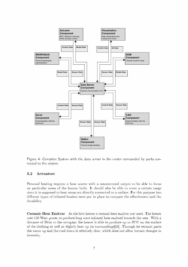
Figure 4: Complete System with the data server in the center surrounded by parts con-nected to the system
3.2 Actuators
Personal heating requires a heat source with a concentrated output to be able to focuson particular zones of the human body. It should also be able to cover a certain rangesince it is supposed to heat areas not directly connected to a surface. For this purpose twodi�erent types of infrared heaters were put in place to compare the e�ectiveness and thedurability.
Ceramic Heat Emitter As the �rst heater a ceramic heat emitter was used. The heateruses 150 Watt power to produce long wave infrared heat emitted towards the user. With adistance of 30cm to the occupant the heater is able to produce up to 35◦C on the surfaceof the clothing as well as slightly heat up its surroundings[13]. Through its ceramic partsthe warm-up and the cool-down is relatively slow, which does not allow instant changes inintensity.
7
Infrared Heat Lamp For the second approach a infrared heat lamp was used. Sameas the ceramic heater the lamp produces long wave infrared heat with this one using 150Watt[4]. A great advantage of the lamp is that it turns on instantly, creating the maximumheat without parts needing time to warm up. Unfortunately it also emits a strong red lightwhich might cause inconveniences for the occupants.
Controller To control and change the values requested from the raspberry pi(3.3) aactuator control GUI has been put in place. In the GUI the user can choose betweendi�erent controllers for the actuators to test di�erent scenarios of algorithms. The alreadyexisting controllers consisted of a PID-Controller as well as a static-value controller. Totest the practicability of the setup a new, very simple, controller was put in place:
Percentage output value for the actuators as P:
P = 100− s · TIfr
s : value generated through the feedback of the application
TIfr : Temperature value of the corresponding surface taken from the infrared Camera
This controller was only created to test this speci�c setup and is supposed to be replacedby a machine learning controller at a later date.
3.3 Raspberry Pi
The Raspberry Pi is a system on a chip computer which has depending on its versiondi�erent hardware specs. In this project the Model 3B was used which features 4 coresat 1.2 GHz, 1GB RAM, Ethernet, 40-pin GPIO as well as USB-ports and HDMI output.Its small scale combined with the Ethernet adapter, that supports HTTP, and the 40-pinGPIO header, which makes it able to communicate with hardware and micro-controllers,makes it perfect for small scale controlling and administration work.
The actuators are plugged into a power distribution board, which is controlled by a buitl inds2408 micro-controller. The ds2408 micro-controller communicates over One-Wire, whichis a single wire communication protocol, and has 8 programmable output channels turnspeci�c sockets on and o� [15][14]. The Raspberry Pi is connected to the ds2408 via One-Wire and passes 8 bits, each corresponding to one channel on the ds2408, to the controllerto turn a speci�c channel on or of.
The Raspberry Pi keeps a Python script running to communicate with the server mentionedin 3.1 and to pass the status to the ds2408. In the script are 2 threads. The �rst one isresponsible for acquiring data from the server. It sends a http POST request via Ethernetto retrieve the power output for each actuator, which is stored on the server as a percentagevalue. The second thread runs a loop from 0 to 100 with each turn sending the 8 bits tothe DS2408 to turn actuators on or o�. This loop is designed to simulate a pulse widthmodulation (PWM) output signal which could not directly be implemented due to the
8

Figure 5: Raspberry Pi connected to the distribution board
hardware of the power distribution board. The percentage values for the di�erent actuatorsare passed to the loop in order to turn them o�, when their speci�c value is reached.
3.4 Camera Setup
Infrared radiation Infrared radiation consists of electromagnetic radiation with longerwave lengths than the light visible to the human eye. The human eye is only capableof seeing colors with a wavelength ranging from 400 to 700 nanometers (nm). Infrareddirectly extends on the upper end of the visible spectrum after the color red, ranging from700 nanometers to 1 millimeter. It is commonly divided into di�erent sub-groups [6][12]:
• Near-infrared (IR-A DIN) ranging from 0.75 to 1.4 micrometer wavelength
• Short-wavelength infrared (IR-B DIN) ranging from 1.4 to 3 micrometer wavelength
• Mid-wavelength infrared (IR-C DIN) ranging from 3 to 8 micrometer wavelength
• Long-wavelength infrared (IR-C DIN) ranging from 8 to 15 micrometer wavelength
• Far infrared ranging from 15 to 1000 micrometer wavelength
The radiation itself does not contain heat in any way. In order to generate heat theradiation has to hit a object. The molecules on the surface of the object will start to moveand thus generate heat.
Infrared Camera Infrared cameras are in their base functionality not very di�erent froma "normal" camera. While a "normal" camera detects re�ected electromagnetic radiationin the visible spectrum, the infrared camera does the same for the infrared spectrum. Tobe able to detect infrared radiation certain substances are required. For the wavelengths ofshort to long wavelength infrared objectives of Germanium, Germanium alloy or zinc saltare required to be able to focus the radiation. The camera used in this speci�c setup wasa Flir A35. It has a power over Ethernet output which transfers all data gathered directlyto application running on a computer.
9
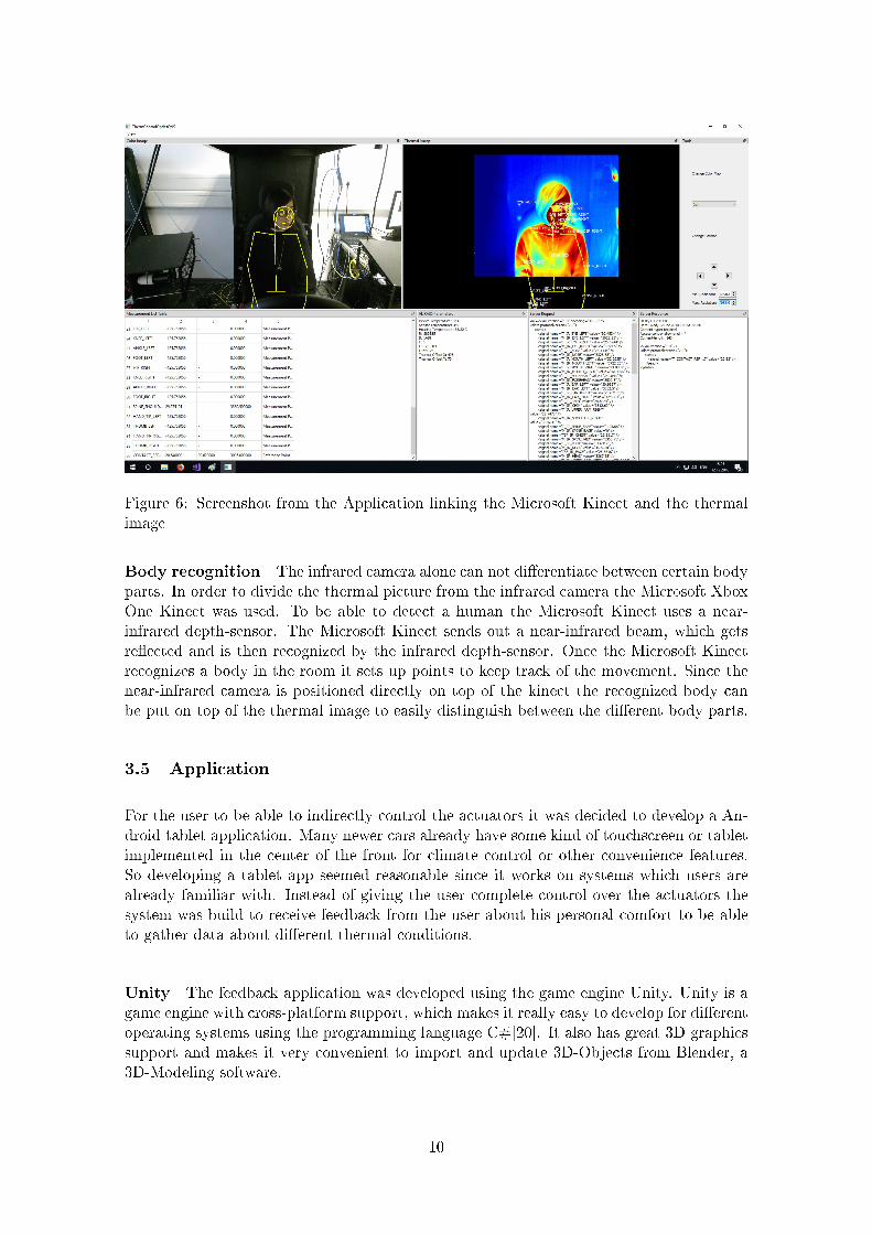
Figure 6: Screenshot from the Application linking the Microsoft Kinect and the thermalimage
Body recognition The infrared camera alone can not di�erentiate between certain bodyparts. In order to divide the thermal picture from the infrared camera the Microsoft XboxOne Kinect was used. To be able to detect a human the Microsoft Kinect uses a near-infrared depth-sensor. The Microsoft Kinect sends out a near-infrared beam, which getsre�ected and is then recognized by the infrared depth-sensor. Once the Microsoft Kinectrecognizes a body in the room it sets up points to keep track of the movement. Since thenear-infrared camera is positioned directly on top of the kinect the recognized body canbe put on top of the thermal image to easily distinguish between the di�erent body parts.
3.5 Application
For the user to be able to indirectly control the actuators it was decided to develop a An-droid tablet application. Many newer cars already have some kind of touchscreen or tabletimplemented in the center of the front for climate control or other convenience features.So developing a tablet app seemed reasonable since it works on systems which users arealready familiar with. Instead of giving the user complete control over the actuators thesystem was build to receive feedback from the user about his personal comfort to be ableto gather data about di�erent thermal conditions.
Unity The feedback application was developed using the game engine Unity. Unity is agame engine with cross-platform support, which makes it really easy to develop for di�erentoperating systems using the programming language C#[20]. It also has great 3D graphicssupport and makes it very convenient to import and update 3D-Objects from Blender, a3D-Modeling software.
10
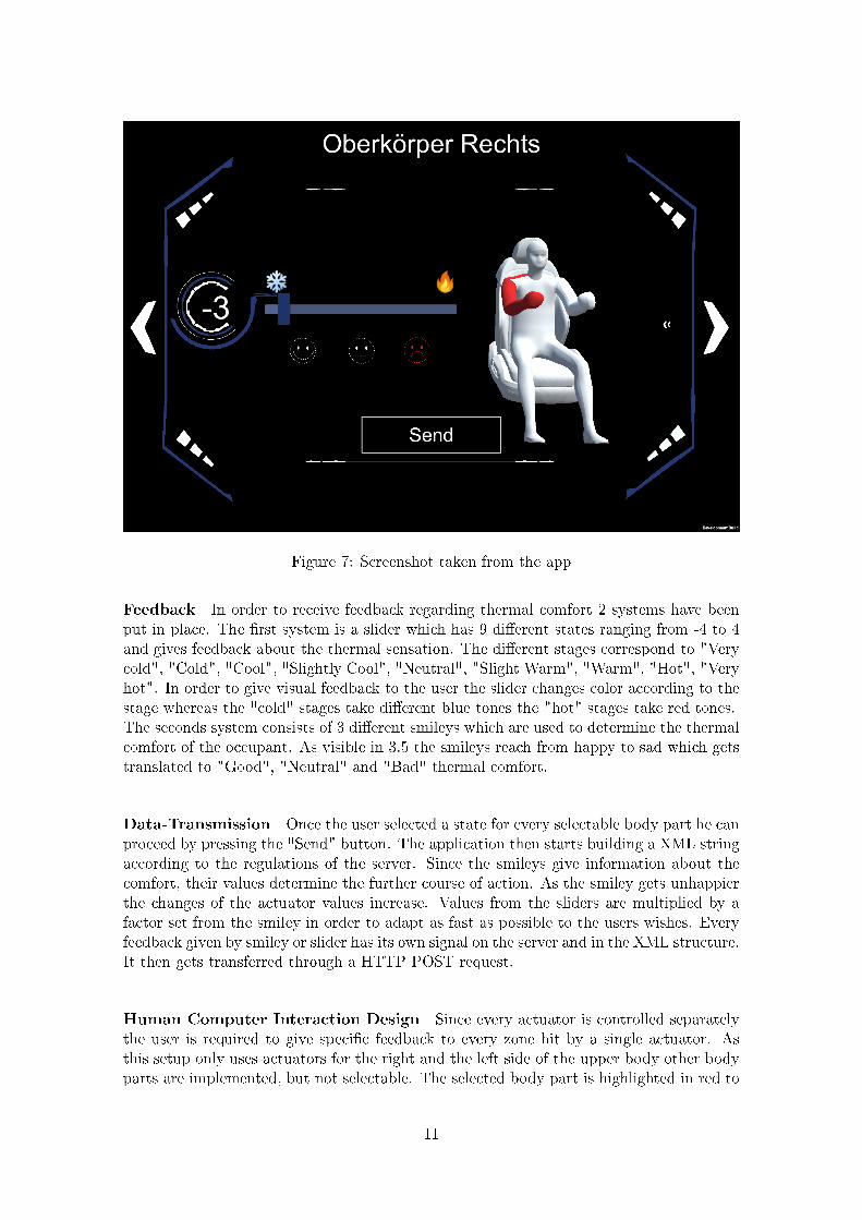
Figure 7: Screenshot taken from the app
Feedback In order to receive feedback regarding thermal comfort 2 systems have beenput in place. The �rst system is a slider which has 9 di�erent states ranging from -4 to 4and gives feedback about the thermal sensation. The di�erent stages correspond to "Verycold", "Cold", "Cool", "Slightly Cool", "Neutral", "Slight Warm", "Warm", "Hot", "Veryhot". In order to give visual feedback to the user the slider changes color according to thestage whereas the "cold" stages take di�erent blue tones the "hot" stages take red tones.The seconds system consists of 3 di�erent smileys which are used to determine the thermalcomfort of the occupant. As visible in 3.5 the smileys reach from happy to sad which getstranslated to "Good", "Neutral" and "Bad" thermal comfort.
Data-Transmission Once the user selected a state for every selectable body part he canproceed by pressing the "Send" button. The application then starts building a XML stringaccording to the regulations of the server. Since the smileys give information about thecomfort, their values determine the further course of action. As the smiley gets unhappierthe changes of the actuator values increase. Values from the sliders are multiplied by afactor set from the smiley in order to adapt as fast as possible to the users wishes. Everyfeedback given by smiley or slider has its own signal on the server and in the XML structure.It then gets transferred through a HTTP POST request.
Human Computer Interaction Design Since every actuator is controlled separatelythe user is required to give speci�c feedback to every zone hit by a single actuator. Asthis setup only uses actuators for the right and the left side of the upper body other bodyparts are implemented, but not selectable. The selected body part is highlighted in red to
11
be easily recognizable without having to read the text displaying the name. In order torecognize button clicks as well as the slider changing its value a haptic force-feedback wasimplemented. Upon change of state the tablet will vibrate indicating a button or sliderhas changed its status.
3.6 Test-Setup
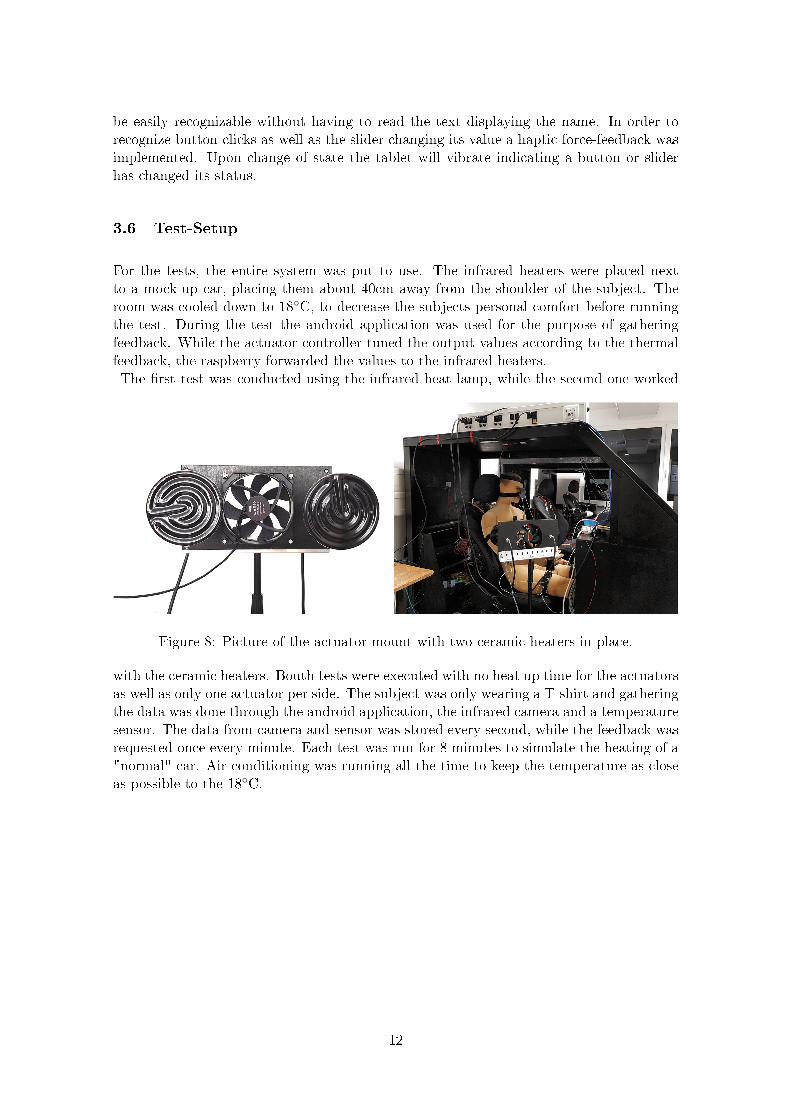
For the tests, the entire system was put to use. The infrared heaters were placed nextto a mock-up car, placing them about 40cm away from the shoulder of the subject. Theroom was cooled down to 18◦C, to decrease the subjects personal comfort before runningthe test. During the test the android application was used for the purpose of gatheringfeedback. While the actuator controller tuned the output values according to the thermalfeedback, the raspberry forwarded the values to the infrared heaters.The �rst test was conducted using the infrared heat lamp, while the second one worked
Figure 8: Picture of the actuator mount with two ceramic heaters in place.
with the ceramic heaters. Bouth tests were executed with no heat up time for the actuatorsas well as only one actuator per side. The subject was only wearing a T-shirt and gatheringthe data was done through the android application, the infrared camera and a temperaturesensor. The data from camera and sensor was stored every second, while the feedback wasrequested once every minute. Each test was run for 8 minutes to simulate the heating of a"normal" car. Air conditioning was running all the time to keep the temperature as closeas possible to the 18◦C.
12

4 Results
In this section the results of the tests will be presented. The two tests were run on 2di�erent days around the same day time only changing the actuators used for the heating.
4.1 Heat Lamp
The �rst test was run using the heat lamp in the actuator setup. During the test theMicrosoft Kinect often lost track of the body, which resulted in spikes in the upper graphof �gure 9. The "Upper Arm Right" area was a�ected a lot stronger than the "Upper ArmLeft" area, which created a huge temperature gap up to 15◦C at certain points during themeasurements. The controller responsible for the thermal camera as well as the MicrosoftKinect crashed from the time stamp of 18:23 to 18:25, which is marked down as red in�gure 9.
18:22 18:24 18:26 18:28 18:30Time Dec 12, 2018
0
5
10
15
20
25
30
35
40
Tem
pera
ture
in °
C
Body Surface Temperature
Upper Arm RightUpper Arm Left
18:22 18:24 18:26 18:28 18:30Time Dec 12, 2018
50
60
70
80
90
100
Pow
er O
utpu
t %
Actuator Power Output
Upper Arm RightUpper Arm Left
Figure 9: Data gathered during the �rst test using the infrared lamp
13
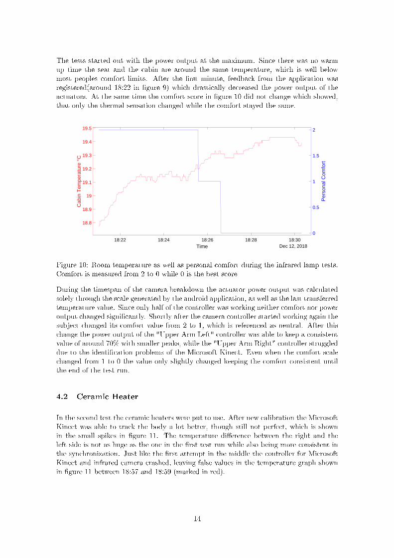
The tests started out with the power output at the maximum. Since there was no warmup time the seat and the cabin are around the same temperature, which is well belowmost peoples comfort limits. After the �rst minute, feedback from the application wasregistered(around 18:22 in �gure 9) which drastically decreased the power output of theactuators. At the same time the comfort score in �gure 10 did not change which showed,that only the thermal sensation changed while the comfort stayed the same.
18:22 18:24 18:26 18:28 18:30Time Dec 12, 2018
18.8
18.9
19
19.1
19.2
19.3
19.4
19.5
Cab
in T
empe
ratu
re °
C
0
0.5
1
1.5
2
Per
sona
l Com
fort
Figure 10: Room temperature as well as personal comfort during the infrared lamp tests.Comfort is measured from 2 to 0 while 0 is the best score
During the timespan of the camera breakdown the actuator power output was calculatedsolely through the scale generated by the android application, as well as the last transferredtemperature value. Since only half of the controller was working neither comfort nor poweroutput changed signi�cantly. Shortly after the camera controller started working again thesubject changed its comfort value from 2 to 1, which is referenced as neutral. After thischange the power output of the "Upper Arm Left" controller was able to keep a consistentvalue of around 70% with smaller peaks, while the "Upper Arm Right" controller struggleddue to the identi�cation problems of the Microsoft Kinect. Even when the comfort scalechanged from 1 to 0 the value only slightly changed keeping the comfort consistent untilthe end of the test run.
4.2 Ceramic Heater
In the second test the ceramic heaters were put to use. After new calibration the MicrosoftKinect was able to track the body a lot better, though still not perfect, which is shownin the small spikes in �gure 11. The temperature di�erence between the right and theleft side is not as huge as the one in the �rst test run while also being more consistent inthe synchronization. Just like the �rst attempt in the middle the controller for MicrosoftKinect and infrared camera crashed, leaving false values in the temperature graph shownin �gure 11 between 18:57 and 18:59 (marked in red).
14

18:53 18:54 18:55 18:56 18:57 18:58 18:59 19:00 19:01 19:02Time Dec 13, 2018
0
5
10
15
20
25
30
35
40
Tem
pera
ture
in °
C
Body Surface Temperature
Upper Arm RightUpper Arm Left
18:54 18:55 18:56 18:57 18:58 18:59 19:00 19:01 19:02Time Dec 13, 2018
70
75
80
85
90
95
100
Pow
er O
utpu
t %
Actuator Power Output
Upper Arm RightUpper Arm Left
Figure 11: Data gathered during the second test using the ceramic heater
Same as in the �rst test the power output starts out at 100%. The �rst change of thepower output is registered after approximately 3 minutes. Together with the comfort scorein �gure 12 which is still at 2 at the moment of change it can be deducted the subjects�rst impression of "cold" did not change until 3 minutes into the test. Even though thepower output changed the comfort score did not improve, meaning that only the feelingof cold got very slightly better. The next change in output power occurred between 18:58and 18:59. At this speci�c time the comfort score still remained at 2 marking it as slightlywarmer, but still unacceptable.
A �nal change was registered between 18:59 and 19:00 dropping the power output downto around 75%. This time the comfort score did change from to 2 to 1, marking it asacceptable. As this was the �nal change the comfort score remained at 1 until the testended, leaving it at only acceptable.The cabin temperature, as well as in the �rst test, kept
15

18:54 18:55 18:56 18:57 18:58 18:59 19:00 19:01 19:02Time Dec 13, 2018
18.2
18.4
18.6
18.8
19
19.2
19.4
19.6
Cab
in T
empe
ratu
re °
C
0.2
0.4
0.6
0.8
1
1.2
1.4
1.6
1.8
2
Per
sona
l Com
fort
Figure 12: Room temperature as well as thermal comfort during the ceramic heater tests.Comfort is measured from 2 to 0 while 0 is the best score
rising until the end.
4.3 Comparison
Directly comparing �gure 9 and �gure 11 the di�erence in data quality considering the bodysurface temperature becomes very clear. The �rst attempts data, especially for "UpperArm Right" is inconsistent and shows from time to time values normally not possible forthe upper human body. Comparing the comfort scores the inconsistency of the thermalcamera value output did not a�ect the comfort negatively. The comfort for the heat lamptest shown in �gure 10 was able to reach a "Good" score in 5 to 6 minutes. The comfortregarding the ceramic heater could not reach a "Good" score in the entire test run and onlychanged to "Neutral" after about 6 minutes(�gure 12). In bouth tests the cabin heated upat around the same speed, not indicating any di�erences in the systems used.
16

5 Discussion
In this section the results will be further discussed and elaborated. First the test will beportrayed separately. Following that will be a comparison of both systems focusing on theadvantages and disadvantages as well as the practicability.
5.1 First Test Run
Body recognition was the biggest problem during the �rst test. The depth image of thekinect often mistook the car seat for the human, leading to the multiple spikes as well asthe huge temperature gap in the upper graph of �gure 9. The crash in the kinect andinfrared camera controller occurred due to a pointer error, which was known but could notbe resolved until the time of the tests. Knowing this it was decided to run the tests withthe defect software as �xing the error would take to much time in the scope of this speci�cpaper.
During the �rst change of power output the comfort score in �gure 10 did not change. Dueto the algorithm used by the actuator controller to calculate the power output (3.2) it canbe deducted, that the thermal sensation changed from "Very Cold" to something aroundthe hot scale of the android application. The infrared lamp can instantly transfer the 150watt into thermal heat transmitted to the subject. With the lamp running on maximumpower output the subject was instantly feeling too hot instead of too cold, which had to betuned down in order to be comfortable. Since the actuators get controlled over a simulatedPWM-Signal the on and o� circles of the lamp are fairly long leading to a uncomfortablefeeling and hardships during �ne tuning. Using a dimmer, which the lamp is capable o�,might strongly increase the comfort score through the smoother control.
As the power output began to stabilize around 70% the comfort score changed to "Good",indicating a comfortable experience. With 70% of the power used and two actuators inplace for each side the system needs about 210 watt. Since during the test no other formof heating was used the power output might be reduced even further with more systems,like a heated seat, in place. A normal electric vehicle takes from 2 to 6 kWh to run the airheater[9]. Using a combination of infrared lamps and heated seats as well as other systemsgreatly reduces the power needed to provide a comfortable driving experience.
5.2 Second Test Run
In the second test body recognition responded a lot better. During this test the subjectwas asked to watch the screen and check, if the kinect might loose track of the body andcorrect its position if needed. The temperature gap in the upper graph of �gure 11 mightbe caused by a seam on the fabric of the subjects T-shirt, which cant be said for sure.
The �rst 3 Minutes there was no change in the power output, which translates into thestats "Very Cold" and "Bad" in the android application, where these values were set for thestart of the test(�gure 11). Ceramic heaters do not instantly transfer heat like a infraredlamp. In order to transfer infrared radiation the sluggishness of the ceramic has to beovercome. It also transfers heat not only into the direction pointed, but also into the area
17

around the heater head, especially above it. This resulted in a lot slower warm up processand the discomfort of the subject prevailing until about 4 minutes into the test. After thetest was �nished the comfort score in �gure 12 still prevailed at 1 which pointed out, thatafter 8 minutes the ceramic heater was not able to transfer enough heat for the subjectto feal comfortable. This marks it as problematic since normal air heating engines wouldgenerally be able to convey a comfortable feeling after running for 8 minutes at a poweroutput between 75% and 100%.
Even with the power running on 100% most of the time the two 150 watt heaters prevailmore e�cient than a normal air heating engine. Though the heat up process plays a hugefactor as it is too slow for people to accept it as a promising alternative.
5.3 Pros and Cons
Both the infrared lamp as well as the ceramic heater provide great energy e�ciency com-pared to the heat pump normally used in electric vehicles. Since the infrared lamp caninstantly change a persons perception from cold to hot it has a great advantage over theceramic heater in terms of e�ciency. It also produces most of the heat on the surface ofthe object it was pointed at, while the ceramic heater looses a lot of heat in all directions.The ceramic heater might be more e�cient in heating up a room, but is not suited forpersonal heating as it is too sluggish in its adaptability.
A big downside of the infrared lamp is the light. The lamp still shines in a red light makingit a possible distraction during driving in electric vehicles. Since this setup only used asimulated PWM the light always put out its full potential. A dimmer might be able to toneit down enough to still provide enough heat while not a�ecting the vision of a car occupanton a greater scale. Further testing using a dimmer as well as di�erent light settings has tobe done in order to determine the usability in cars.
While the ceramic heater does not transmit any kind of light its other downsides make ittoo unattractive in direct comparison to the heat lamp. With a faster warm up time anda more concentrated heat output the practicability would greatly increase. But to reachfaster warm up times more energy has to be used leaving the question open if the trade o�is worth the decrease in energy e�ciency.
18

6 Conclusion
In this seminar paper the advantages of personalized heating and air-conditioning werepresented. Especially the advantages of infrared radiation in terms of personalized heatingin electric vehicles compared to normal air heating engines were illustrated. Between thetwo systems introduced the heat lamp clearly excelled as more e�cient in terms of comfortand usability. Its fast heat up of surfaces confronted with the infrared radiation not onlymakes it comparable to standardized heating engines but makes it a strong competitor interms of providing comfort in the shortest amount of time.
Furthermore, tests have to be conducted in order to determine the usability in cars re-garding the light as a distraction factor. Using a dimmer instead of a low frequency PWMcontrol should greatly reduce light output and keep distraction at a minimum while alsoincreasing the overall comfort.
The algorithm used by the actuator controller was able to provide su�cient comfort duringthe tests. Though this controller heavily relies on user feedback, which cant be requestedevery minute from a driving human. In order to reduce human interaction with the feed-back system a supervised learning algorithm could be put in place. Training the actuatorcontroller to recognize the human as well as providing output values correlating to environ-ment in�uences like sun or rain should reduce human interaction with the heat controlleras well as increasing the comfort provided by the entire system. For this to be possible alot of su�cient data has to be generated in order to train the algorithm.
For the human recognition to work e�ciently the camera setup consisting of the MicrosoftKinect and thermal camera has to be improved in terms of stability and robustness.. Asshown in this paper the small spikes of loosing track of the body did not in�uence thepower output in a major way. Although the crashes of the application froze the actuatorfor several minutes leaving power output almost unchanged, which greatly in�uenced thecomfort of the user over time.
Overall a alternative for heating in electric vehicles could be introduced as well as perceivedcomfortable during user testing. Further the use of an Android application for user feedbackassesment and subsequent adaptive actuator control in cooperation with a existing softwaresystem was tested. Test results showed that the system is able to provide su�cient thermalcomfort by compensating a low environment temperature. Data obtained by further usertesting can be likely used to train a fully autonomous system.
19

References
[1] Bruce Banter. Touch screens and touch surfaces are enriched by haptic force-feedback.Information Display, 26(3):26�30, 2010.
[2] Adilson Borges, Márcia Maurer Herter, and Jean-Charles Chebat. �it was not thatlong!�: The e�ects of the in-store tv screen content and consumers emotions on con-sumer waiting perception. Journal of Retailing and Consumer Services, 22:96�106,2015.
[3] JE Brooks and KC Parsons. An ergonomics investigation into human thermal com-fort using an automobile seat heated with encapsulated carbonized fabric (ecf). Er-gonomics, 42(5):661�673, 1999.
[4] Philips Lighting Holding B.V. Infrared industrial heat incandescent.https://www.assets.lighting.philips.com/is/content/PhilipsLighting/
fp923801445507-pss-de_de. 05.12.2018.
[5] Philips Lighting Holding B.V. Philips hue - das smarte licht für dein zuhause. https://www2.meethue.com/de-de. 04.12.2018.
[6] James Byrnes. Unexploded ordnance detection and mitigation. Springer Science &Business Media, 2008.
[7] Prafulla Nath Dawadi, Diane Joyce Cook, and Maureen Schmitter-Edgecombe. Au-tomated cognitive health assessment from smart home-based behavior data. IEEEjournal of biomedical and health informatics, 20(4):1188�1194, 2016.
[8] International Organization for Standardization. ISO 7730 2005-11-15 Ergonomics ofthe Thermal Environment: Analytical Determination and Interpretation of ThermalComfort Using Calculation of the PMV and PPD Indices and Local Thermal ComfortCriteria. International standards. ISO, 2005.
[9] Gene. Tips for staying warm in your tesla this winterwithout killing battery range. https://www.teslarati.com/
energy-saving-tips-tesla-subzero-weather-using-seat-heaters/. 28.11.2018.
[10] Deutsche Automobil Treuhand GmbH. Dat-report 2007, 2007.
[11] Deutsche Automobil Treuhand GmbH. Dat-report 2018, 2018.
[12] Roy Henderson. Wavelength considerations. Instituts für Umform-und Hochleistungs,7, 2007.
[13] Rolf C. Hagen Inc. Ceramic heat emitter. http://www.exo-terra.com/en/products/ceramic_heater.php. 05.12.2018.
[14] maxim integratedTM. 1-wire communication through software. https://www.
maximintegrated.com/en/app-notes/index.mvp/id/126. 4.12.2018.
[15] maxim integratedTM. Ds2408. https://datasheets.maximintegrated.com/en/ds/DS2408.pdf. 04.12.2018.
[16] American Society of Heating, Refrigerating and Air Conditioning Engineers (Atlanta,Georgia). ANSI/ASHRAE Standard 55-2013: Thermal Environmental Conditions forHuman Occupancy. ASHRAE standard. ASHRAE, 2013.
20

[17] Sonja Rümelin and Andreas Butz. How to make large touch screens usable while driv-ing. In Proceedings of the 5th International Conference on Automotive User Interfacesand Interactive Vehicular Applications, pages 48�55. ACM, 2013.
[18] Carolin Schmidt, Daniel Wölki, and Christoph van Treeck. De�nition einer�Äquivalenten kontakttemperatur� als bezugsgröÿe zur bewertung der ergonomis-chen qualität von kontaktbasierten klimatisierungssystemen in fahrzeugen. In FAT-SCHRIFTENREIHE 314, 2018.
[19] Richard Stubbe. Surging demand for electric vehicles. https://www.bloomberg.com/businessweek. 15.12.2018.
[20] Unity Technologies. Unity. https://unity3d.com/. 21.11.2018.
[21] Alladi Venkatesh. Digital home technologies and transformation of households. In-formation Systems Frontiers, 10(4):391�395, 2008.
[22] Mingyu Wang, Edward Wolfe, Debashis Ghosh, Je�rey Bozeman, Kuo-huey Chen,Taeyoung Han, Hui Zhang, and Edward Arens. Localized cooling for human com-fort. SAE International Journal of Passenger Cars-Mechanical Systems, 7(2014-01-0686):755�768, 2014.
21


