Personalizing Head Related Transfer Functions for EarablesZhijian Yang
University of Illinois at Urbana ChampaignRomit Roy Choudhury
University of Illinois at Urbana Champaign
ABSTRACTHead related transfer functions (HRTF) describe how sound signalsbounce, scatter, and diffract when they arrive at the head, and traveltowards the ear canals. HRTFs produce distinct sound patterns thatultimately help the brain infer the spatial properties of the sound,such as its direction of arrival, \ . If an earphone can learn the HRTF,it could apply the HRTF to any sound and make that sound appeardirectional to the user. For instance, a directional voice guide couldhelp a tourist navigate a new city.
While past works have estimated human HRTFs, an importantgap lies in personalization. Today’s HRTFs are global templatesthat are used in all products; since human HRTFs are unique, aglobal HRTF only offers a coarse-grained experience. This papershows that by moving a smartphone around the head, combinedwith mobile acoustic communications between the phone and theearbuds, it is possible to estimate a user’s personal HRTF. Ourpersonalization system, UNIQ, combines techniques from channelestimation, motion tracking, and signal processing, with a focus onmodeling signal diffraction on the curvature of the face. The resultsare promising and could open new doors into the rapidly growingspace of immersive AR/VR, earables, smart hearing aids, etc.
CCS CONCEPTS• Computer systems organization → Embedded and cyber-physical systems; • Human-centered computing → Ubiqui-tous and mobile computing; Interaction techniques.
KEYWORDSHead Related Transfer Function (HRTF), Spatial Audio, VirtualAcoustics, HRTF Personalization, Earables, AR, VRACM Reference Format:Zhijian Yang and Romit Roy Choudhury. 2021. Personalizing Head RelatedTransfer Functions for Earables. In ACM SIGCOMM 2021 Conference (SIG-COMM ’21), August 23–27, 2021, Virtual Event, USA. ACM, New York, NY,USA, 14 pages. https://doi.org/10.1145/3452296.3472907
1 INTRODUCTIONHumans can inherently sense the direction \ from which a soundarrives at their ears. The human brain essentially analyzes the timedifference of the sounds across the two ears andmaps this difference
Δ𝑡 to \ . If the mapping was one-to-one, then the estimation of \would be easy. Unfortunately, the mapping is one-to-many, meaningthat for a given Δ𝑡 , there are many possible \s. Figure 1(a) shows anexample where all points on the (red) hyperbola produce identicalΔ𝑡 at the ears. How can humans still disambiguate the direction\? The answer lies in what is classically known as the head relatedtransfer function (HRTF), explained next.
Figure 1: Humans identify sound direction through (a) time differ-ence of arrival, and (b) pinna multipath.
Briefly, the sounds that actually enter the ear-canal is influencedby the shape of the human head and the pinna of the ear (shownin Figure 1(b)). The pinna produces micro-echoes to the arrivingsignal, while the 3D curvature of the head bends (or diffracts) thesignals [16, 22, 29]. The net result is that the eardrum receives asophisticated signal pattern that helps the brain disambiguate \ . Insummary, one can view the head (including the pinna) as a filter thatalters the signal depending on its angle of arrival \ . In frequencydomain, this filter is called head related transfer function (HRTF).
Knowing HRTF for each \ opens new possibilities in spatial acous-tics. An earphone could take any normal sound 𝑠 (𝑡), apply the(left and right) HRTFs for a desired \ , and play the two sounds inthe corresponding earbuds [25, 59]. The brain would perceive thissound as directional, as if it is arriving from an angle \ with respectto the head. Applications could be many, ranging from immersiveAR/VR, to gaming, to assisted technology for blind individuals [52].
For instance, (1) users may no longer need to look at maps tonavigate from point A to point B; a voice could say “follow me”in the ears, and walking towards the perceived direction of thevoice could bring the user to her destination. Blind people mayparticularly benefit from such a capability. (2) A virtual-realitymeeting could be held through immersive acoustic experiences.Members could pick their seats in a virtual meeting room andeach member could hear the others from the direction of theirrelative configuration. (3) Gaming and other 3D applications wouldnaturally benefit. Each musical instrument in an AR/VR orchestracould be fixed to a specific location around the head. Even if the
SIGCOMM ’21, August 23–27, 2021, Virtual Event, USA Zhijian Yang and Romit Roy Choudhury
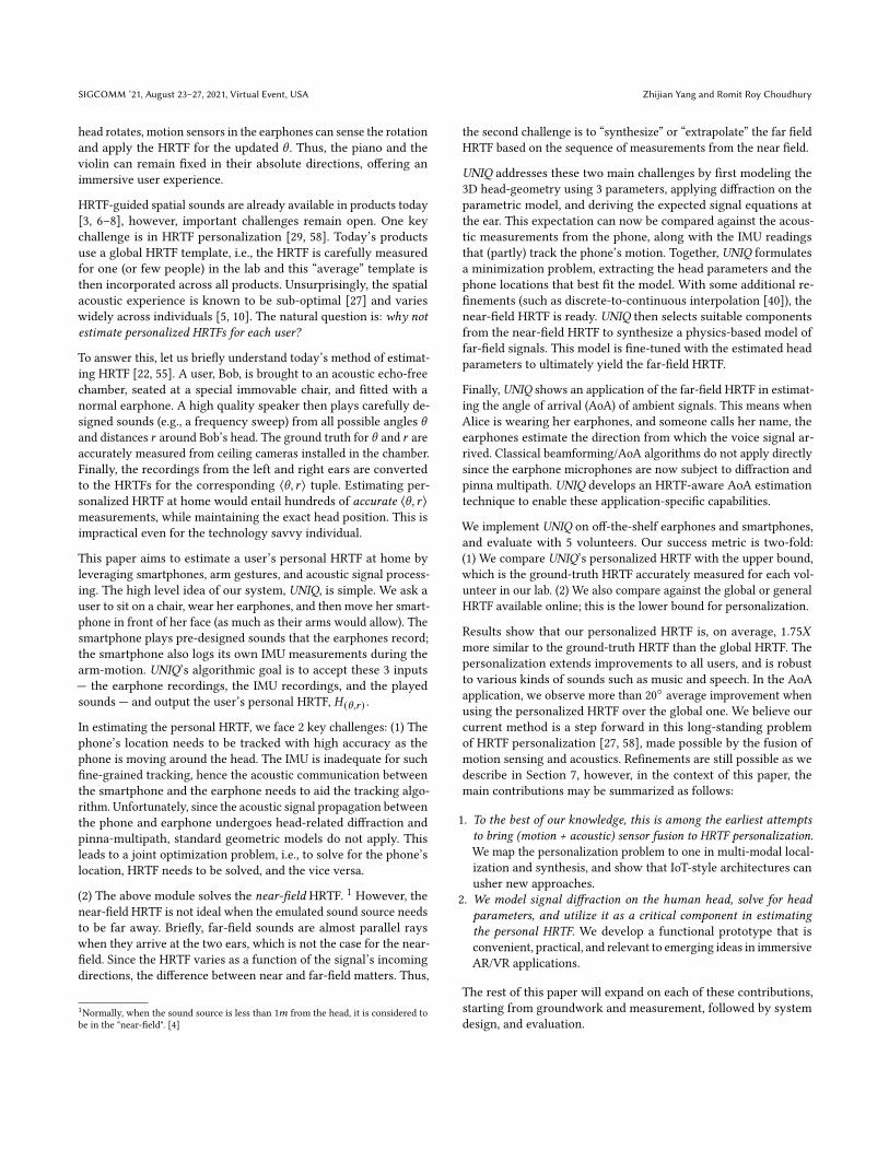
head rotates, motion sensors in the earphones can sense the rotationand apply the HRTF for the updated \ . Thus, the piano and theviolin can remain fixed in their absolute directions, offering animmersive user experience.
HRTF-guided spatial sounds are already available in products today[3, 6–8], however, important challenges remain open. One keychallenge is in HRTF personalization [29, 58]. Today’s productsuse a global HRTF template, i.e., the HRTF is carefully measuredfor one (or few people) in the lab and this “average” template isthen incorporated across all products. Unsurprisingly, the spatialacoustic experience is known to be sub-optimal [27] and varieswidely across individuals [5, 10]. The natural question is: why notestimate personalized HRTFs for each user?
To answer this, let us briefly understand today’s method of estimat-ing HRTF [22, 55]. A user, Bob, is brought to an acoustic echo-freechamber, seated at a special immovable chair, and fitted with anormal earphone. A high quality speaker then plays carefully de-signed sounds (e.g., a frequency sweep) from all possible angles \and distances 𝑟 around Bob’s head. The ground truth for \ and 𝑟 areaccurately measured from ceiling cameras installed in the chamber.Finally, the recordings from the left and right ears are convertedto the HRTFs for the corresponding ⟨\, 𝑟 ⟩ tuple. Estimating per-sonalized HRTF at home would entail hundreds of accurate ⟨\, 𝑟 ⟩measurements, while maintaining the exact head position. This isimpractical even for the technology savvy individual.
This paper aims to estimate a user’s personal HRTF at home byleveraging smartphones, arm gestures, and acoustic signal process-ing. The high level idea of our system, UNIQ, is simple. We ask auser to sit on a chair, wear her earphones, and then move her smart-phone in front of her face (as much as their arms would allow). Thesmartphone plays pre-designed sounds that the earphones record;the smartphone also logs its own IMU measurements during thearm-motion. UNIQ’s algorithmic goal is to accept these 3 inputs— the earphone recordings, the IMU recordings, and the playedsounds — and output the user’s personal HRTF, 𝐻 (\,𝑟 ) .
In estimating the personal HRTF, we face 2 key challenges: (1) Thephone’s location needs to be tracked with high accuracy as thephone is moving around the head. The IMU is inadequate for suchfine-grained tracking, hence the acoustic communication betweenthe smartphone and the earphone needs to aid the tracking algo-rithm. Unfortunately, since the acoustic signal propagation betweenthe phone and earphone undergoes head-related diffraction andpinna-multipath, standard geometric models do not apply. Thisleads to a joint optimization problem, i.e., to solve for the phone’slocation, HRTF needs to be solved, and the vice versa.
(2) The above module solves the near-field HRTF. 1 However, thenear-field HRTF is not ideal when the emulated sound source needsto be far away. Briefly, far-field sounds are almost parallel rayswhen they arrive at the two ears, which is not the case for the near-field. Since the HRTF varies as a function of the signal’s incomingdirections, the difference between near and far-field matters. Thus,
1Normally, when the sound source is less than 1𝑚 from the head, it is considered tobe in the "near-field". [4]
the second challenge is to “synthesize” or “extrapolate” the far fieldHRTF based on the sequence of measurements from the near field.
UNIQ addresses these two main challenges by first modeling the3D head-geometry using 3 parameters, applying diffraction on theparametric model, and deriving the expected signal equations atthe ear. This expectation can now be compared against the acous-tic measurements from the phone, along with the IMU readingsthat (partly) track the phone’s motion. Together, UNIQ formulatesa minimization problem, extracting the head parameters and thephone locations that best fit the model. With some additional re-finements (such as discrete-to-continuous interpolation [40]), thenear-field HRTF is ready. UNIQ then selects suitable componentsfrom the near-field HRTF to synthesize a physics-based model offar-field signals. This model is fine-tuned with the estimated headparameters to ultimately yield the far-field HRTF.
Finally, UNIQ shows an application of the far-field HRTF in estimat-ing the angle of arrival (AoA) of ambient signals. This means whenAlice is wearing her earphones, and someone calls her name, theearphones estimate the direction from which the voice signal ar-rived. Classical beamforming/AoA algorithms do not apply directlysince the earphone microphones are now subject to diffraction andpinna multipath. UNIQ develops an HRTF-aware AoA estimationtechnique to enable these application-specific capabilities.
We implement UNIQ on off-the-shelf earphones and smartphones,and evaluate with 5 volunteers. Our success metric is two-fold:(1) We compare UNIQ’s personalized HRTF with the upper bound,which is the ground-truth HRTF accurately measured for each vol-unteer in our lab. (2) We also compare against the global or generalHRTF available online; this is the lower bound for personalization.
Results show that our personalized HRTF is, on average, 1.75𝑋more similar to the ground-truth HRTF than the global HRTF. Thepersonalization extends improvements to all users, and is robustto various kinds of sounds such as music and speech. In the AoAapplication, we observe more than 20◦ average improvement whenusing the personalized HRTF over the global one. We believe ourcurrent method is a step forward in this long-standing problemof HRTF personalization [27, 58], made possible by the fusion ofmotion sensing and acoustics. Refinements are still possible as wedescribe in Section 7, however, in the context of this paper, themain contributions may be summarized as follows:
1. To the best of our knowledge, this is among the earliest attemptsto bring (motion + acoustic) sensor fusion to HRTF personalization.We map the personalization problem to one in multi-modal local-ization and synthesis, and show that IoT-style architectures canusher new approaches.
2. We model signal diffraction on the human head, solve for headparameters, and utilize it as a critical component in estimatingthe personal HRTF. We develop a functional prototype that isconvenient, practical, and relevant to emerging ideas in immersiveAR/VR applications.
The rest of this paper will expand on each of these contributions,starting from groundwork and measurement, followed by systemdesign, and evaluation.
Personalizing Head Related Transfer Functions for Earables SIGCOMM ’21, August 23–27, 2021, Virtual Event, USA
2 GROUNDWORK ON HRTFThis section sheds light on the 2 fundamental constructs of HRTFs:(1) the acoustic channel introduced by a user’s pinna, and (2) diffrac-tion caused by curvature of faces/heads. This should also help char-acterize the gap between the global and personal HRTF.
■ Does the pinna’s effect vary with angle of arrival, \? Recallthat when a sound signal impinges on the pinna, it bounces andscatters in complex ways, reaching the ear-drum at staggered timeinstants. To test if this effect is sensitive to the angle of arrival\ , we ask a user, Alice, to wear an in-ear microphone on her leftear. We play short chirps from a speaker on the left side of Alice,so that the head’s effects do not interfere with the microphonerecording (we intend to only measure the impact of the pinna). Thespeaker is moved in a semi-circle, starting from the front of thenose (\ = 0◦) and ending at the back of the head (\ = 180◦), withmeasurements every 10◦. With 18 audio measurements, denoted𝐴(\ ), we now compute the cross-correlation 𝑐 between 𝐴(\𝑖 ) and𝐴(\ 𝑗 ), 𝑖, 𝑗 = {1, 2, . . . , 18} as
𝑐 =𝑚𝑎𝑥 (𝑓 (𝜏)) =𝑚𝑎𝑥 (∞∑
𝑡=−∞𝐴(\𝑖 ) (𝑡) · 𝐴(\ 𝑗 ) (𝑡 + 𝜏))
where 𝜏 is the relative delay between 2 audio signals.
Figure 2(a) shows the results. Evidently, the correlation matrix isstrongly diagonal, implying that the pinna’s impulse response isquite sensitive to \ , with almost a 1:1 mapping. This is consistentacross our 5 volunteers, suggesting that the pinna indeed plays animportant role in the human’s ability to perceive directional sounds(at a resolution of ≈ 20◦).
■ Does the pinna’s effect vary across users? The natural nextquestion is whether the pinna’s response varies across users for thesame \ . For this, we cross-correlate the audio measurements from2 users, 𝐴𝐴𝑙𝑖𝑐𝑒 (\𝑖 ) and 𝐴𝐵𝑜𝑏 (\𝑖 ), ∀𝑖 . Figure 2(b) shows the results.Clearly, Alice and Bob’s pinnas do not match well, for example,Alice’s recording (angle 1) at angle 80◦ corresponds well with Bob’srecording (angle 2) at angle 140◦. This means, when global HRTFsare used in ear-devices, the resolution for directional sounds can beno higher than ≈ 60◦, suggesting that the gap between global andpersonal is not negligible. Thus global HRTF obviously degradesuser experience.
.0 20 40 60 80 10
012
014
016
018
0
Angle 2 (deg.)
0
20
40
60
80
100
120
140
160
180
Angle
1 (
deg.)
0.5
0.6
0.7
0.8
0.9
1
0 20 40 60 80 100
120
140
160
180
Angle 2 (deg.)
0
20
40
60
80
100
120
140
160
180
Angle
1 (
deg.)
0.3
0.4
0.5
0.6
0.7
Figure 2: Pinna’s effect: (a) Diagonal confusionmatrix for the sameuser, across different angle of arrival, \ . (b) For different people,their pinna’s transfer functions are markedly different.
■ Do signals diffract on a person’s face/head? Is diffractiondistinct across users?Diffraction is the phenomenon where waves bend around the cor-ners of an obstacle or through an aperture into the region of geomet-rical shadow of the obstacle/aperture [38]. From the physics of wave
propagation (see detailed explanations in [9]), diffraction dependson the relative wavelength of the signal compared to the size ofthe object [9], as shown in figure 3. With larger wavelength, soundwaves exhibit far more diffraction than, say, light or RF signals.
.
Figure 3: Diffraction illustration: a wave will propagate into theregion of geometric shadow. The larger the wavelength comparedto the aperture, greater is the diffraction [2].
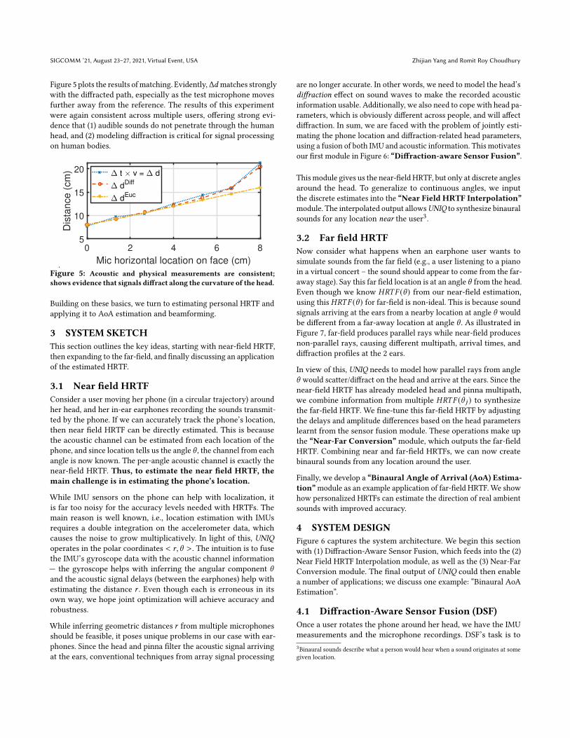
Figure 4 illustrates an experiment to characterize diffraction on thehuman face, particularly due to the curvature of the cheek. We askAlice to wear a reference microphone on her right ear; a second(test)microphone is pasted at 6 different locations on the left part ofher face (starting with the tip of the nose and ending at the ear). Anelectronic speaker (shown on the user’s right) plays a chirp and wecalculate the chirp’s time difference of arrival (TDoA), Δ𝑡 , betweenthe 2 microphones2. Multiplying speed of sound 𝑣 with Δ𝑡 , we getthe difference in physical distance that the signal has traveled fromthe speaker to the 2 microphones: Δ𝑑 = 𝑣 · Δ𝑡 .
Figure 4: Experiment to test for signal diffraction on the curvatureof the human head.
In parallel, using precise measurements from a camera, and a soft-tape that can bend along the curvature of the face, we obtain thefollowing distances: the Euclidian distance from the speaker 𝑆 tothe reference microphone 𝑅, 𝑑𝐸𝑢𝑐(𝑆,𝑅) , the Euclidian distance to thetest microphone 𝑇 , 𝑑𝐸𝑢𝑐(𝑆,𝑇 ) , and the distance along the diffracted-
path to the test microphone𝑇,𝑑𝑑𝑖 𝑓 𝑓(𝑆,𝑇 ) . The test for diffraction is noweasy: Does Δ𝑑 derived from audio recordings better match withthe Euclidian path difference Δ𝑑𝐸𝑐𝑢 or the diffracted path Δ𝑑𝐷𝑖𝑓 𝑓 ,where
Δ𝑑𝐸𝑐𝑢 = 𝑑𝐸𝑢𝑐(𝑆,𝑇 ) − 𝑑𝐸𝑢𝑐(𝑆,𝑅)
Δ𝑑𝐷𝑖𝑓 𝑓 = 𝑑𝐸𝑢𝑐(𝑆,𝑇 ) − 𝑑𝐷𝑖𝑓 𝑓
(𝑆,𝑅)
2This is possible because the 2 microphones are synchronized with a wire.
SIGCOMM ’21, August 23–27, 2021, Virtual Event, USA Zhijian Yang and Romit Roy Choudhury
Figure 5 plots the results ofmatching. Evidently,Δ𝑑 matches stronglywith the diffracted path, especially as the test microphone movesfurther away from the reference. The results of this experimentwere again consistent across multiple users, offering strong evi-dence that (1) audible sounds do not penetrate through the humanhead, and (2) modeling diffraction is critical for signal processingon human bodies.
.
0 2 4 6 8
Mic horizontal location on face (cm)
5
10
15
20
Dis
tance (
cm
) t v = d
dDiff
dEuc
Figure 5: Acoustic and physical measurements are consistent;shows evidence that signals diffract along the curvature of the head.
Building on these basics, we turn to estimating personal HRTF andapplying it to AoA estimation and beamforming.
3 SYSTEM SKETCHThis section outlines the key ideas, starting with near-field HRTF,then expanding to the far-field, and finally discussing an applicationof the estimated HRTF.
3.1 Near field HRTFConsider a user moving her phone (in a circular trajectory) aroundher head, and her in-ear earphones recording the sounds transmit-ted by the phone. If we can accurately track the phone’s location,then near field HRTF can be directly estimated. This is becausethe acoustic channel can be estimated from each location of thephone, and since location tells us the angle \ , the channel from eachangle is now known. The per-angle acoustic channel is exactly thenear-field HRTF. Thus, to estimate the near field HRTF, themain challenge is in estimating the phone’s location.
While IMU sensors on the phone can help with localization, itis far too noisy for the accuracy levels needed with HRTFs. Themain reason is well known, i.e., location estimation with IMUsrequires a double integration on the accelerometer data, whichcauses the noise to grow multiplicatively. In light of this, UNIQoperates in the polar coordinates < 𝑟, \ >. The intuition is to fusethe IMU’s gyroscope data with the acoustic channel information— the gyroscope helps with inferring the angular component \and the acoustic signal delays (between the earphones) help withestimating the distance 𝑟 . Even though each is erroneous in itsown way, we hope joint optimization will achieve accuracy androbustness.
While inferring geometric distances 𝑟 from multiple microphonesshould be feasible, it poses unique problems in our case with ear-phones. Since the head and pinna filter the acoustic signal arrivingat the ears, conventional techniques from array signal processing
are no longer accurate. In other words, we need to model the head’sdiffraction effect on sound waves to make the recorded acousticinformation usable. Additionally, we also need to cope with head pa-rameters, which is obviously different across people, and will affectdiffraction. In sum, we are faced with the problem of jointly esti-mating the phone location and diffraction-related head parameters,using a fusion of both IMU and acoustic information. This motivatesour first module in Figure 6: “Diffraction-aware Sensor Fusion”.
This module gives us the near-field HRTF, but only at discrete anglesaround the head. To generalize to continuous angles, we inputthe discrete estimates into the “Near Field HRTF Interpolation”module. The interpolated output allowsUNIQ to synthesize binauralsounds for any location near the user3.
3.2 Far field HRTFNow consider what happens when an earphone user wants tosimulate sounds from the far field (e.g., a user listening to a pianoin a virtual concert – the sound should appear to come from the far-away stage). Say this far field location is at an angle \ from the head.Even though we know 𝐻𝑅𝑇𝐹 (\ ) from our near-field estimation,using this 𝐻𝑅𝑇𝐹 (\ ) for far-field is non-ideal. This is because soundsignals arriving at the ears from a nearby location at angle \ wouldbe different from a far-away location at angle \ . As illustrated inFigure 7, far-field produces parallel rays while near-field producesnon-parallel rays, causing different multipath, arrival times, anddiffraction profiles at the 2 ears.
In view of this, UNIQ needs to model how parallel rays from angle\ would scatter/diffract on the head and arrive at the ears. Since thenear-field HRTF has already modeled head and pinna multipath,we combine information from multiple 𝐻𝑅𝑇𝐹 (\ 𝑗 ) to synthesizethe far-field HRTF. We fine-tune this far-field HRTF by adjustingthe delays and amplitude differences based on the head parameterslearnt from the sensor fusion module. These operations make upthe “Near-Far Conversion” module, which outputs the far-fieldHRTF. Combining near and far-field HRTFs, we can now createbinaural sounds from any location around the user.
Finally, we develop a “Binaural Angle of Arrival (AoA) Estima-tion”module as an example application of far-field HRTF. We showhow personalized HRTFs can estimate the direction of real ambientsounds with improved accuracy.
4 SYSTEM DESIGNFigure 6 captures the system architecture. We begin this sectionwith (1) Diffraction-Aware Sensor Fusion, which feeds into the (2)Near Field HRTF Interpolation module, as well as the (3) Near-FarConversion module. The final output of UNIQ could then enablea number of applications; we discuss one example: “Binaural AoAEstimation”.
4.1 Diffraction-Aware Sensor Fusion (DSF)Once a user rotates the phone around her head, we have the IMUmeasurements and the microphone recordings. DSF’s task is to3Binaural sounds describe what a person would hear when a sound originates at somegiven location.
Personalizing Head Related Transfer Functions for Earables SIGCOMM ’21, August 23–27, 2021, Virtual Event, USA
.
Figure 6: System Architecture: UNIQ estimates both near and far-field HRTF taking inputs from the phone IMU and earphone microphone.The system pipeline is composed of 3 modules (diffraction-aware sensor fusion, near field HRTF interpolation, and near-far conversion)followed by an application that estimates binaural AoA from the personalized HRTF.
.
Figure 7: Illustration of near and far HRTF for angle \ .
accept these measurements as inputs and output both the head’sgeometric parameters and the phone’s location. For this, let usmodel diffraction first.
Modeling Head DiffractionFigure 8 shows a simplified version of signal diffraction on thehead. To model this, we start by approximating the head shape as aconjunction of two half-ellipses, attached at the ear locations. Thisis necessary since the head is not symmetric between the frontand back, hence spherical models have been avoided in literature[49]. The head shape can now be expressed through a 3-parameterset, 𝐸 = (𝑎, 𝑏, 𝑐), where 𝑎, 𝑏, and 𝑐 are the axis lengths of the twoellipses. Now, assuming the sound source is towards the right ofthe head, the signal would not penetrate through the head to arriveto the left ear, but would bend over/around the left cheek of theuser (diffraction). With head parameters 𝐸 known and for a givenphone location 𝑃 , we can estimate the time at which the diffractedsignals would arrive at the two ears respectively.
Figure 9 shows the measured acoustic channel at the two ears forthe above scenario (the channels are estimated by deconvolving thereceived signal with the known source signal). Clearly, the channelhas multiple peaks (or taps) since the signal reflects on the face andthese reflections also diffract. However, we are interested only inthe first peaks at the two ears, since they are the ones that reliablycapture the relationship between the phone and ear locations. This
.Figure 8: Sound waves arriving from phone at location P willdiffract around the head before reaching the two ears.
is because the subsequent peaks in the channel are paths that arriveafter reflecting on various points on the face, and while they maybe useful to image the face, they are not necessary for our purposesof phone localization. Thus, UNIQ extracts the first peaks from thetwo channels and uses the relative delay Δ𝑡 to connect the phonelocation and the head-shape in a common framework, as shown inequation 1:
Δ𝑡 = relative delay for first peak in ℎ𝐿, ℎ𝑅= 𝑓 (Diffraction)= 𝑓 (𝑎, 𝑏, 𝑐, 𝑃)
(1)
This serves as the basis for diffraction-aware sensor fusion.
Sensor Fusion AlgorithmNow, consider the IMU readings from the phone and the soundrecordings from the in-ear microphone (the phone and the ear-phones are synchronized). UNIQ infers the phone’s inertial rotationfrom the IMU’s gyroscope, which translates to the phone’s polarangle relative to the head. Of course, this still does not give thephone location (since the distance to the head is unknown).
SIGCOMM ’21, August 23–27, 2021, Virtual Event, USA Zhijian Yang and Romit Roy Choudhury
.
0 20 40 60 80
Sample
-1
-0.5
0
0.5
Am
plit
ud
e Left
Right
Figure 9: Channel impulse response: first tap corresponds todiffraction path
On the other hand, if the parameters 𝐸 = (𝑎, 𝑏, 𝑐) are known, therelative delay from the acoustic channels can give phone location(with some ambiguity since 2 front/back locations can produce thesame delay at the ears). Said differently, IMUs and acoustic channelsdo not individually solve the localization problem, but contributeadequate information to (over) determine the system of equations.This is exactly why sensor fusion helps – UNIQ jointly solves forhead parameter and phone location through a fusion of IMU andacoustics.
The steps of the fusion algorithm can now be laid out:1. As the smartphone rotates around the head, the IMU measure-
ments are integrated to obtain the phone’s orientation 𝛼 . Since weask users to face the phone’s screen towards their eyes, 𝛼 shouldbe exactly equal to the polar angle \ (illustrated in Figure 10(a)).Over time, the phone orientation and the polar angle change,denoted as \𝑖 and 𝛼𝑖 , 𝑖 = 1, 2, . . . , 𝑁 .
2. Using the measured acoustic channels, and pretending we knowthe head parameters 𝐸, we can localize the phone and map it tothe polar angle \𝑖 (𝐸).
3. When the parameters 𝐸 are correct, the 𝛼𝑖 and \𝑖 should match∀𝑖 = 1, 2, . . . , 𝑁 .
4. Due to noise in IMU and acoustics, we minimize the squared error∥𝛼 − \ ∥2 with decision variables as 𝐸:
𝐸𝑜𝑝𝑡 = 𝑎𝑟𝑔𝑚𝑖𝑛𝐸
( 𝑁∑𝑖=1
𝛿2𝑖
)= 𝑎𝑟𝑔𝑚𝑖𝑛
𝐸
𝑁∑𝑖=1
(𝛼𝑖 − \𝑖 (𝐸)
)2(2)
With larger 𝑁 , i.e., more measurements from the user, the 𝐸𝑜𝑝𝑡converges better.
Estimating Polar Angle \𝑖 (𝐸) in Step 2 above:Estimating 𝛼 from IMU readings is a straightforward gyroscopeintegration. However, phone location and angle \𝑖 from the acousticmodel is slightly more involved. Assume 𝑡1 and 𝑡2 are the diffractionpath delays (first tap delays) for signals that arrive at the left andright ear, respectively. Now, assuming we already have the headparameters 𝐸, then we can draw 2 trajectories (as shown in Fig-ure 10(b)). The first one is the trajectory of points from which thediffraction-based delay to the left ear is 𝑡1. The second trajectory isthe one from which the diffraction-based delay to the right ear is𝑡2. The phone’s location must be at the intersection of these 2 tra-jectories. From the figure, we can observe that the two trajectoriesactually intersect at two points 𝐴 and 𝐵, with polar angles \𝐴 (𝐸),\𝐵 (𝐸), and polar radius 𝑟𝐴 , 𝑟𝐵 . To disambiguate, we will pick the\ (𝐸) that is closer to the IMU angle estimation 𝛼 . By plugging \ (𝐸)and 𝛼 into the above Equation (2) and performing the optimization,UNIQ derives the optimal head parameter 𝐸𝑜𝑝𝑡 .
As a final step, we combine the IMU and acoustic localization resultsto obtain the estimated location of the phone as
𝑃 (𝜙𝑖 , 𝑟𝑖 ) = 𝑃((\𝑖 (𝐸𝑜𝑝𝑡 ) + 𝛼𝑖 )/2, 𝑟𝑖
)(3)
By indexing the measured HRTFs with the estimated phone lo-cations, we complete the near-field HRTF estimation at discretesample points. To obtain a continuous near-field HRTF, we employinterpolation.
4.2 Near field HRTF interpolationIt is difficult for a user to rotate the phone in continuous trajectoriesaround their head. Thus, we allow users to position the phone at asmany convenient locations as possible, and interpolate across otherlocations (shown in Figure 11). Interpolation is crucial because (1)downstream applications may intend to place sounds in any arbi-trary location in the near-field; (2) as we will see soon, continuousnear-field HRTF aids in synthesizing the far-field HRTF.
.
Figure 11: Near-field HRTF (linear) interpolation
The idea behind near-field HRTF interpolation is actually simple. Ifavailable measurements are from polar angles 𝜙1, 𝜙2, ...𝜙𝑁 aroundthe head, the interpolation module basically takes adjacent near-field HRTFs and linearly interpolates for all angles between 𝜙𝑖 and𝜙𝑖+1. Of course, the HRTFs from 𝜙𝑖 and 𝜙𝑖+1 need to be aligned
Personalizing Head Related Transfer Functions for Earables SIGCOMM ’21, August 23–27, 2021, Virtual Event, USA
carefully along their first taps before the interpolation; otherwisespurious echoes will get injected into the HRTF. To this end, weconvert the HRTFs into the time domain impulse responses (i.e.,HRIRs), align them, and interpolate. Finally, observe that for a giveninterpolated location 𝐿 and HRTF 𝐻𝐿 , we can partly assess thequality of interpolation (i.e., by modeling the diffraction from theknown head parameters 𝐸 and the location 𝐿). If the interpolatedHRTF deviates from this model, we adjust the channel taps tomatch the expected time-difference and the amplitudes. These tunedchannels for every angle [0, 180] is converted back to the frequencydomain, and declared as the final near-field HRTF.
By now, we have covered the system design for measuring thepersonalized near-field HRTF for a given user. Building on this,we will then show how we estimate the far-field HRTF from ournear-field estimations.
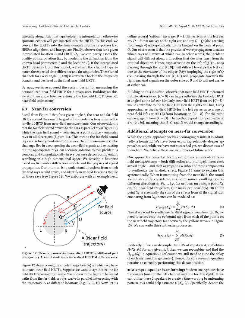
4.3 Near-far conversionRecall from Figure 7 that for a given angle \ , the near and far-fieldHRTFs are not the same. The goal of this module is to synthesize thefar-field HRTF from near-field measurements. Our observation isthat the far-field sound arrives to the ears as parallel rays (Figure 12),while the near field sound – behaving as a point source – emanatesrays in all directions (Figure 13). This means the far field soundrays are actually contained in the near field measurements. Thechallenge lies in decomposing the near-field signals and extractingout the appropriate rays. An accurate solution to this problem iscomplex and computationally heavy because decomposing entailssearching in a high dimensional space. We develop a heuristicbased on first-order diffraction models and the physics of signalpropagation. Our intuition is to understand directions from whichfar-field rays would arrive, and identify near-field locations that lieon those rays (see Figure 12). We elaborate with an example next.
.
Figure 12: Near-far conversion: near-field HRTF on different partof trajectory A would contribute to far-field HRTF at different ears.
Figure 12 shows a roughly circular trajectory (A) on which we haveestimated near-field HRTFs. Suppose we want to synthesize the farfield HRTF arriving from angle \ as shown in the figure. The signalpaths from the far-field, or rays, arrive in parallel, intersecting withthe trajectory A at different locations (e.g., B, C, D) Now, let us
define several “critical” rays: ray 𝐵 − 𝐿 that arrives at the left ear,ray 𝐷 − 𝑅 that arrives at the right ear, and ray 𝐶 −𝑄 (also arrivingfrom angle \ ) is perpendicular to the tangent on the head at point𝑄 . Our observation is that the physics of wave propagation dictateswhich rays will arrive at which ear. In other words, the incidentsignal will diffract along a direction that deviates least from itsoriginal direction. Hence, rays arriving on the left of 𝑄 (i.e., onespassing through the arc [𝐶, 𝐵]) will diffract towards the left eardue to the curvature of the ellipse. Rays impinging the right of 𝑄(i.e., passing through the arc [𝐶, 𝐷]) will propagate towards theright ear. And signals on the outer side of 𝐵 and 𝐷 will not arriveat either ear.
Building on this intuition, observe that near-field HRTF measuredfrom locations in arc [𝐶 −𝐵] can help synthesize the far-field HRTFat angle \ at the left ear. Similarly, near-field HRTF from arc [𝐶−𝐷]would contribute to the far-field HRTF on the right ear. Thus, UNIQapproximates the far-field HRTF for the left ear as an average ofnear-field left-ear HRTFs from locations in [𝐶 − 𝐵]; for the rightear, average is from [𝐶 − 𝐷]. The method repeats for each value of\ ∈ [0, 180], meaning that 𝐵, 𝐶 , and 𝐷 would change accordingly.
Additional attempts on near-far conversionWhile the above approach yields encouraging results, it is admit-tedly a heuristic. We have been exploring relatively deeper ap-proaches, and while we have not succeeded yet, we discuss two ofthem here. We believe these are rich topics of future work.
Our approach is aimed at decomposing the components of near-field measurements – both diffraction and multipath from eacharrival angle – and then aggregating a subset of these componentsto synthesize the far-field effect. Figure 13 aims to explain thissystematically. When transmitting from the near-field, the soundsource should be considered as a point source, emitting rays indifferent directions \1, \2, ..., \𝑁 . Let us focus on a single point 𝑋𝑘on the near field trajectory. Our measured near-field HRTF forpoint 𝑋𝑘 is essentially the sum of the effects from all the signal raysemanating from 𝑋𝑘 , hence can be modeled as:
𝐻𝑛𝑒𝑎𝑟 (𝑋𝑘 ) =𝑁∑𝑖=0
𝐻 (𝑋𝑘 , \𝑖 ) (4)Now if we want to synthesize far-field signals from direction \𝑙 , weneed to select only the \𝑙 -bound rays from each of the points onthe near field trajectory (as shown by the yellow arrows in Figure13). We can write this synthesize process as:
𝐻𝑓 𝑎𝑟 (\𝑙 ) =𝑀∑𝑖=0
𝐻 (𝑋𝑖 , \𝑙 ) (5)
Evidently, if we can decouple the RHS of equation 4, and obtain𝐻 (𝑋𝑘 , \𝑖 ) for any given 𝑘, 𝑖 , then we can recombine and find the𝐻𝑓 𝑎𝑟 (\𝑙 ) in equation 5 (of course we still need to tune the delayof each ray based on geometry). Hence, the core research questionpertains to correctly performing this decomposition.
■Attempt 1: speaker beamforming:Modern smartphones have2 speakers (one for the left channel and one for the right). If wecan utilize these 2 speakers to create a time-varying beamformingpattern, this could help estimate 𝐻 (𝑋𝑘 , \𝑖 ). Specifically, denote the
SIGCOMM ’21, August 23–27, 2021, Virtual Event, USA Zhijian Yang and Romit Roy Choudhury
Figure 13: Near-far conversion attempts: if we can decouple near-field HRTF into rays, then far-field HRTF essentially needs to ex-tract out one ray from each near-field location and recombine withappropriate weights.
beamforming pattern at one time instance as 𝑤 (\ ), which is afunction of angle \ . Then we can rewrite Equation 4 as
𝐻𝑛𝑒𝑎𝑟 (𝑋𝑘 ) =𝑁∑𝑖=0
𝑤 (\𝑖 ) · 𝐻 (𝑋𝑘 , \𝑖 ) (6)
By creating time varying beamforming patterns𝑤𝑡 (\ ) – by chang-ing the relative phase and amplitude of the 2 speakers – we cangenerate multiple equations, one for each time instance. This couldenable us to solve for 𝐻 (𝑋𝑘 , \𝑖 ). The difficulty, however, is that the2 speakers are unable to create a spatially narrow beam pattern.This eventually leads to the system of equations being ill-rankedand causes large errors for the estimated 𝐻 (𝑋𝑘 , \𝑖 ).
■ Attempt 2: blind decoupling: The net effect of 𝐻 (𝑋𝑘 , \𝑖 ) oneach signal ray has 2 components. First, the diffraction around thehead creates a delay and attenuation. Second, the signal bouncesfrom the pinna, creating an effect we call the pinna multipath.Hence, the net effect on each signal ray can be expressed as
𝐻 (𝑋𝑘 , \𝑖 ) = 𝐴𝑖𝛿 (𝜏𝑖 ) ∗ ℎ𝑘 (7)
where 𝛿 is the Dirac delta function, 𝜏𝑖 is the ray’s diffraction delay,𝐴𝑖 is signal attenuation, and ℎ𝑘 is the time domain pinna multi-path channel (∗ denotes convolution here). We plug Equation 7 toEquation 4, and we can have
𝐻𝑛𝑒𝑎𝑟 (𝑋𝑘 ) =𝑁∑𝑖=0
𝐴𝑖𝛿 (𝜏𝑖 ) ∗ ℎ𝑘 (8)
Now, if we can estimate∑𝑁𝑖=0𝐴𝑖𝛿 (𝜏𝑖 ) and ℎ𝑘 separately, the de-
coupling can be solved. 𝛿 (𝜏𝑖 ) can be estimated from diffractiongeometry, but we do not know 𝐴𝑖 and ℎ𝑘 . This becomes a blinddecomposition problem. While sparsity opportunities could helpsolve this problem, we realize that our physics based signal modelmay be inadequate to capture the sophisticated real-world signalpropagation patterns. We believe machine learning techniques arerelevant here; we leave that to future work.
4.4 Interface to ApplicationsThe near and far-field HRTFs estimated by UNIQ can now be ex-ported to earphone applications as a lookup table. The table isindexed by \ , and for each \𝑖 , there are 4 vector entries:
\𝑖 : ⟨𝐻 𝑙𝑒 𝑓 𝑡𝑛𝑒𝑎𝑟 , 𝐻
𝑟𝑖𝑔ℎ𝑡𝑛𝑒𝑎𝑟 ⟩ , ⟨𝐻
𝑙𝑒 𝑓 𝑡
𝑓 𝑎𝑟, 𝐻
𝑟𝑖𝑔ℎ𝑡
𝑓 𝑎𝑟⟩
Each HRTF is obviously a channel filter, so when an applicationintends to synthesize a binaural sound 𝑆 from a desired location 𝐿,the application first determines if 𝐿 is nearby or far-away, and theangle \𝑖 of the location 𝐿 relative to the head. If 𝐿 is far-away, thenthe application filters the sound as
𝑌𝑙𝑒 𝑓 𝑡 = 𝐻𝑙𝑒 𝑓 𝑡
𝑓 𝑎𝑟𝑆, 𝑌𝑟𝑖𝑔ℎ𝑡 = 𝐻
𝑟𝑖𝑔ℎ𝑡
𝑓 𝑎𝑟𝑆
The earphone now plays the two sounds, 𝑌𝑙𝑒 𝑓 𝑡 and 𝑌𝑟𝑖𝑔ℎ𝑡 on theleft and right ears, respectively. The user perceives the sound to becoming from angle \𝑖 from a far-away location. We next presentone potential application that can benefit from the estimated HRTFs.
4.5 Binaural Angle of Arrival (AoA)Understanding the incoming direction of real ambient sounds (rel-ative to the user’s head) can enable smart earphones to fuel newapplications. For instance, earphones could serve as hearing aids,and beamform in the direction of a desired speech signal; thus, Aliceand Bob could listen to each other more clearly by wearing head-phones in a noisy bar. In another example, earphones could analyzethe AoAs of music echoes in a shopping mall and enable navigationby triangulating the music speakers. Now, to accurately estimatethe AoAs of these ambient sounds, the earphones need to applythe HRTF (since conventional AoA techniques are not designedto cope with the HRTF distortions). This motivates HRTF-awareAoA estimation, with both unknown source signals (such as Aliceand Bob’s speech) and known signals (such as those from ambientacoustic speakers).
■ Known source signals: If the source signal is known, we firstextract the acoustic channels from the left and right ears. To now es-timate AoA, we look for the following 2 features from the channels:(1) the first tap relative delay between left and right channels, and(2) the shape of the time-domain channel. Observe that (1) is im-pacted by head diffraction and (2) is related to the pinna multipath,both embedding information about the signal’s AoA. As mentionedin Section 2, both these features vary across humans. This is whythe personalized HRTF is helpful here. We match these 2 featuresfrom our measured channel against our estimation 𝐻𝑅𝑇𝐹 (\ ) — the\ that maximizes the match is our AoA estimate.
Mathematically, let 𝑡0 be the relative first tap delay from our bin-aural recording, and 𝑡 (\ ) be the same relative delay but for thepersonal HRIR templates estimated for each \ . Also denote 𝑐𝐿 (\ )and 𝑐𝑅 (\ ) as the correlation values for left/right channels with(left/right) HRIR templates for all \ . We define a target matchingfunction𝑇 that contains both relative delay and channel correlationinformation:
𝑇 (\ ) = _ |𝑡0 − 𝑡 (\ ) | + [1 − 𝑐𝐿 (\ )] + [1 − 𝑐𝑅 (\ )] (9)After training for the appropriate _, we find the actual AoA byminimizing the target function.
Personalizing Head Related Transfer Functions for Earables SIGCOMM ’21, August 23–27, 2021, Virtual Event, USA
■ Unknown source signal: For unknown source signals, we canno longer extract the 2 acoustic channels for left and right ears,making it difficult to find the relative first tap delay, or left/rightchannel shape.However, we still have the opportunity to infer the first tap delayfrom the relative channels between the left and right ear-recordings– this can help estimate the AoA.Of course, this is not straightforward since signals arriving at bothears contain a lot of pinna multipath, and thus have poor auto-correlation. This will cause multiple peaks in the relative channel,as shown in Figure 14. Let us assume each peak has a relative delayΔ𝑡𝑖 . Based on our diffraction model, each relative delay Δ𝑡𝑖 canfurther translate into 2 AoAs: 𝐴𝑜𝐴𝑖,1 and 𝐴𝑜𝐴𝑖,2 (one for front andone for back). Now our task is to find the true AoA from all thepotential AoAs.
The key idea for disambiguating is to still utilize the time domainshape of the channel. Since we cannot extract the left or rightchannel, our key intuition is to compare the shape of the "relative"channel. Suppose the left ear recording is 𝐿, and right ear 𝑅, inthe frequency domain. Then the relative channel is 𝐿
𝑅. We can
also calculate the relative channel for all angle \ in the personalHRTF template 𝐻𝑅𝑇𝐹𝐿 (\ )
𝐻𝑅𝑇𝐹𝑅 (\ ) . Ideally, for the correct \ , these 2 relativechannels should match:
𝐿
𝑅=
𝐻𝑅𝑇𝐹𝐿 (\ )𝐻𝑅𝑇𝐹𝑅 (\ )
(10)
Since division are sensitive to errors when the denominator is small,we change Equation (10) into a multiplication form:
𝐿 × 𝐻𝑅𝑇𝐹𝑅 (\ ) = 𝑅 × 𝐻𝑅𝑇𝐹𝐿 (\ ) (11)
By plugging all the potential𝐴𝑜𝐴𝑖 ’s (inferred from relative channelpeaks) into the above equation, and finding the one that gives theclosest LHS and RHS, we identify the true AoA.
.
0 1 2 3
Time 10-3
-1
0
1
Am
plit
ud
e Relative Channel
Figure 14: Relative channel between left and right ear:there are multiple channel taps due to poor signal auto-correlation.
By now, we have covered the key system design ideas. We will thenshow some system details.
4.6 Engineering and System Details
■ System frequency response compensation: Before perform-ing HRTF measurements, the first step is to compensate for thefrequency response of the speaker and microphone pair. This isimportant because any channel we estimated would intrinsically
embed this frequency response inside. We estimate frequency re-sponse of the speaker and microphone pair by placing microphoneco-located with speaker and play a flat amplitude chirp signal.
■Tackling roomreflections:The traditional approaches toHRTFmeasurement are conducted in echo-free acoustic chambers. Homeusers obviously do not have access to such “anechoic” chambers.However, we can eliminate room-level echoes as a pre-processingstep in UNIQ. The idea is simple: when users rotate the phonearound their heads, head diffraction and pinna multipath shouldarrive earlier than room reflections. We eliminate the latter channeltaps to exclude room reflections.
■ Automatically correcting user gestures:A user may not be able to rotate the phone around the head in thevery first attempts; practical problems can occur such as the armslowering, the phone spinning, etc. This can affect measurementand downstream accuracy. UNIQ identifies such cases by detectingthat the estimated phone distance to head center 𝑟𝑖 in Equation(3) is too small, or the overall error
∑𝑁𝑖=1 𝛿
2𝑖in equation (2) is too
large. This triggers a message to the user to redo the measurementexercise. With this, we are ready to move to system evaluation.
5 EVALUATIONFigure 15 shows our system setup.UNIQ is implemented on aXiaomi[11] smartphone and a Sound Professionals earphone (model: SP-TFB-2) [1], which supports in-ear microphones. In-ear microphonesare becoming popular and can improve the HRTF quality since thesounds will be recorded closer to the ear-drum. Since our phonedoes not have a front-facing speaker, we connect the audio outputto a small external speaker. User wears the earphone and rotatesthe smartphone (with pasted speaker) around her head.
.
Figure 15: Systemprototype. Left: experimental setup. Right:zoom in to in-ear microphone
.During the measurement process, we collect 100𝐻𝑧 IMU data fromthe phone, and 96𝑘𝐻𝑧 sound recording from the in-ear microphone.The speaker, microphone, and IMU are all synchronized. The dataprocessing pipeline runs on MATLAB. The ground-truth data forsmartphone (and head) locations are obtained from an overheadcamera installed on top of the user’s head.
SIGCOMM ’21, August 23–27, 2021, Virtual Event, USA Zhijian Yang and Romit Roy Choudhury
Figure 16 shows the frequency response of our speaker microphonepair. The response curve is unstable below 50𝐻𝑧 and stabilizesreasonably over [100𝐻𝑧, 10𝑘𝐻𝑧]. This shows that our hardware isnot anything special; in fact, expensive phones and headphonesmay exhibit better frequency response curves. Finally, given thathuman ears are insensitive to sound below 100𝐻𝑧 [13], any standardhardware platform should be adequate to run the UNIQ system.
.
102 103 104
Frequency (Hz)
-60
-40
-20
0
Am
plit
ude (
dB
)
Frequency Response
Figure 16: Frequency response of our speaker-microphonepair. Most hardware platforms exhibit such response curves,if not better [31].
5.1 ResultsPhone Localization AccuracyFigure 17 plots the phone localization angular error in near-field.The X-axis in Figure 17(a) plots the ground-truth polar angle of thephone as viewed from the overhead camera. The Y-axis plotsUNIQ’sestimate of the polar angle as the user rotates her hand. Perfectaccuracy would mean that the plotted points would like on the 𝑋 =
𝑌 diagonal line. Evidently, UNIQ’s localization is consistently quiteaccurate. Figure 17(b) plots the CDF; the median error is 4.8 degrees.The error is mostly due to the difficulty of ensuring the phone’scenter is perfectly facing the user’s own head. Imperfection of theacoustic diffraction model also partly contributes to the errors, butless significantly. Only in rare cases, the phone’s localization errorclimbs to 15 degrees because the volunteer’s movement has deviatedtoo much from the instructions. This adds to the downstream errors,however, wee include these cases since they are a part of real-worldoperating conditions.
.0 50 100 150
Groundtruth Angle
0
50
100
150
Estim
ate
d A
ng
le
0 10 20
Angular Error (Degrees)
0
0.2
0.4
0.6
0.8
1
CD
F
Figure 17: Phone’s angular error for hand-rotation: (a) com-parison with ground truth, (b) error CDF.
Personalized HRTF EstimatesThe HRTF is a vector that completely embeds the head/pinna’sacoustic impulse response. An objective way to evaluate HRTFestimate is to cross-correlate personalized HRTF vector with groundtruth. This will reveal how closely UNIQmatches the truth. Further,plotting correlation between ground truth and global HRTF willalso reveal the improvement of personal over global HRTF.
.
0 50 100 150
Angle (Deg)
0
0.2
0.4
0.6
0.8
1
Corr
ela
tion
UNIQ Global HRIR Gnd HRIR
0 50 100 150
Angle (Deg)
0
0.2
0.4
0.6
0.8
1
Corr
ela
tion
UNIQ Global HRIR Gnd HRIR
Figure 18: Cross-correlation between ground-truth versusUNIQ, global, and another measurement of ground-truthHRIR, for (a) left ear, (b) right ear.
Figure 18 shows the cross-correlations between estimated and gen-eral HRIR against the ground-truth HRIR (error bars representstandard division). We also show the cross-correlation between 2separate measurements of ground-truth HRIR as a reference upperbound. Figure 18(a) plots for the left ear, and Figure 18(b) for theright; in both cases, the sound source was placed on the left ofthe head. Evidently, UNIQ’s estimated HRIR achieves an averagecorrelation of 0.74 and 0.71 for the left and right ear, respectively.In contrast, the general HRIR can attain average correlation of 0.41for both ears. This is a key result, illustrating that:1. Global HRIRs significantly differs from personalized ones.2. UNIQ considerably closes this gap (by a factor of ∼ 1.75𝑋 )For the right ear, our estimated HRTF exhibits higher accuracywhen the angle is ≈0 or ≈180 degrees, but degrade around ≈90degrees. This is because when the phone is at 90 degrees, the rightear microphone is exactly at the opposite side of the speaker, sig-nificantly suppressing the SNR of the received signal, resulting inlower accuracy. Higher quality earphones would certainly benefitin these cases.
Variation across Different VolunteersFigure 19 shows the mean correlation for 5 volunteers (who worethe earphones and performed the smartphone rotation in front of
Personalizing Head Related Transfer Functions for Earables SIGCOMM ’21, August 23–27, 2021, Virtual Event, USA
their head). The two graphs – (a) and (b) – are again for the left andright ear, respectively. The personalization gain is consistent acrossall. Of course, UNIQ estimates the HRTF slightly less accuratelyfor volunteers 4 and 5 compared to volunteers 1, 2, and 3. This isbecause when holding the phone, volunteers 4 and 5 moved thephone a bit too close to the back of their heads, due to their armmovement constraints, (even after automatic correction procedureof UNIQ), leading to sub-optimal estimates in the diffraction model,and downstream far-field estimations.
.1 2 3 4 5
Volunteer #
0
0.2
0.4
0.6
0.8
1
Co
rre
latio
n
UNIQ Global HRIR
1 2 3 4 5
Volunteer #
0
0.2
0.4
0.6
0.8
1
Co
rre
latio
n
UNIQ Global HRIR
Figure 19: Average cross-correlation between estimated /global HRIR and the groundtruth across different volun-teers for (a) left ear, (b) right ear
While the above results are statistical, Figure 20 zooms into fewraw HRTFs in the time domain (called head related impulse response,HRIR). Specifically, the figure shows the (a) best case, (b) averagecase, and the (c) worst case estimation of UNIQ’s HRIR in compari-son to the general HRIR. Evidently, across all 3 cases, our estimatedHRIRs always decode the channel taps at correct locations; thegeneral HRIR makes frequent mistakes. This is primarily due toUNIQ’s ability to capture per-user head and pinna multipath, whichare obviously different from one human to another.
Application of HRTF to AoAA more accurate HRTF implies that ambient sounds can now bebetter analyzed spatially, such as a hearing aid identifying thedirection of an incoming sound. We put this to test by comparingthe AoA error when applying the personalized HRTF from UNIQ,versus the global HRTF. We begin by playing a known source signal(from different locations in the far field) and estimating AoA.Figure 21 plots the CDF of angular AoA error. With UNIQ’s person-alized HRTF producing a median error of 7.8◦, compared to globalHRTF’s median error of 45.3◦. More importantly, the maximumerror of personalized HRTF is 60◦ while the maximum for globalHRTF is > 150◦. This is because a global HRTF suffers considerably
.0 50 100 150
Am
plit
ude
0 50 100 150
Samples
0 50 100 150
UNIQ Groundtruth Global
Figure 20: Sample example HRIRs for (a) best case, (corr =0.96), (b) average case, (corr = 0.85), (c)worst case, (corr = 0.43).Global HRIRs almost always inferior.
.
0 50 100 150 200
Far-field AoA Error, Known Source (Deg)
0
0.5
1
CD
F
UNIQ
Global HRTF
Figure 21: AoA estimation with personalized and globalHRTF using a known source signal. Global HRTF performspoorly since measured signals deviate from HRTF estimate.
from “front-back ambiguity”, i.e., it does not reliably differentiatebetween sounds arriving symmetric front and back angles, such as45◦ north-east and 45◦ south-east. In fact, in 29% of our experiments,using global HRTF caused a front-back confusion.
We repeat the above experiments with unknown source signals,such as when Alice calls Bob (and Bob is wearing a hearing aidsor earphones). Alice’s voice signal is unknown to Bob’s device,however, the ear-devices can still decode Alice’s direction better.We tested with a variety of “unknown” signal categories, such aswhite noise, music, and speech. Figure 22(a)-(c) shows the CDFof AoA error for each of these categories. The personalized HRTFoffers consistent gains across all types of signals; the distributionhas a somewhat heavy tail because, with unknown signals, the front-back ambiguity begins to affect UNIQ as well. The 80 percentile AoAerror with personalized HRTF is within 20◦ for music and whitenoise. The improvement with speech is smaller because speech isdominated by lower frequencies, thus less sensitive to HRTF errors.Figure 22(d) zooms into the front-back cases, since these are crucialfor real applications (we do not want Bob to hear a virtual voice thatcomes from a wrong direction). With UNIQ, the average front-backaccuracy is 82.8% — white noise is highest at 87.2% and speechsignals are lowest at 72.8%. This is because white noise spans over alarge frequency range, offering more information about the acousticchannel; in contrast, speech signals are concentrated on base andharmonic frequencies, revealing less information about the channel.For global HRTF, the front-back accuracy is 59.8%.
SIGCOMM ’21, August 23–27, 2021, Virtual Event, USA Zhijian Yang and Romit Roy Choudhury
.0 50 100 150 200
Far-field AoA Error,White Noise (Deg)
0
0.5
1
CD
F
UNIQ
Global HRTF
0 50 100 150 200
Far-field AoA Error,Music (Deg)
0
0.5
1
CD
F
UNIQ
Global HRTF
0 50 100 150 200
Far-field AoA Error,Speech (Deg)
0
0.5
1
CD
F
UNIQ
Global HRTF
White Noise Music Speech0
0.5
1
Accu
racy
UNIQ
Global HRTF
Figure 22: (a)-(c): AoA estimation error, (d): front-back identification accuracy for an unknown source signal.
6 RELATEDWORK■ Smart earphones and earable computing: With the develop-ment of mobile computing technologies [19], smart earphones arebecoming popular these days. Past works have looked at enablingspatial audio[18, 21, 26, 51] and acoustic augmented reality [15, 54],step counting [44] and motion tracking [53], user authentication[20] and health monitoring [42] on sensor embedded smart ear-phones. This paper, however, adds another building block - personalHRTF to smart earphones. We believe this is a step towards evenbetter functionality on future earables: e.g., more immersive spatialaudio, and smarter beamforming, etc.
■ HRTF personalization: HRTF personalization has gained in-terest in recent years due to the development of VR and AR relatedtechnology. Traditionally people use large speaker arrays insideacoustic chambers to measure HRTF [17, 22], which is obviously notscalable. Some newer work [27, 29, 33, 36, 45, 58] tried to approachthis problem without acoustic hardware from the pure signal pro-cessing perspective. They used acoustic simulation to generate thespecific personalized HRTF for a given user from 3D scans of humanhead. These methods are reported to be slow and computationallyheavy [28]. Moreover, obtaining an accurate 3D scan is also not easy[57]. Few attempts utilize mobile devices for HRTF measurement.[12] is the closest to our work. Their method, however, requiresan external speaker placed on the table, and need to user to tie thesmartphone onto the head, which is not portable. Moreover, theirsetup can be polluted by environmental multipath. Our approach,on the contrary, is novel, fast, and scalable. Users can get theirpersonalized HRTF by simply rotating the phone around the head,in a couple of minutes.
■ Acoustic/wireless sensing and sound source AoA estima-tion: Acoustic/wireless sensing and sound source AoA estimationis a hot research topic in mobile, acoustic, and robotic community[23, 24, 34, 35, 37, 39, 41, 43, 47, 56]. Most past works require amic array for sound AoA estimation [46, 48, 50]. [18, 30, 32] arethe closest to our work, where the authors attempted to estimatesound AoA from artificially made robotic ears. Our problem is morechallenging because past authors can design the robot head andear entirely by themselves thus have full control and understand-ing of the accurate robot HRTF. In our case, we need to find thesound source AoA by extracting features from the not-so-accurateestimated HRTF, which brings about unique challenges.
7 LIMITATIONS AND OPEN PROBLEMS■ 3D HRTF: Our UNIQ prototype estimates the 2D HRTF for users.This may be acceptable, given that human ears exhibit relatively
lower resolution in distinguishing elevation angles. Hence 2D maysuffice for many applications. However, if an application desires3D HRTF, extending UNIQ is viable – the user would now needto move the phone on a sphere around the head, and the motiontracking equations need to be extended to 3D. If this increases thetracking error, perhaps the phone camera can be utilized, enablinga fusion between motion, acoustics, and computer vision. We leavethis to future work.
■ Integrating Room Multipath: As discussed earlier, UNIQ re-moves environmental reverberations through a pre-processing stepin the time domain; this helps minimize the effect of room mul-tipath on the estimated HRTF. However, rendering realistic 3Daudio, especially in an indoor environment, requires that the roomreverberations be embedded into the HRTF. Said differently, a realimmersive experience can only be achieved by filtering the ear-phone sound with both the room impulse response (RIR) and theHRTF. Estimating RIR at home is an interesting but separate re-search question, outside the scope of this paper.
■ User Experience and Externalization: An estimated HRTFis accurate when the user is unable to correctly identify whetherthe sound she hears came from her earphone or an ambient loud-speaker. When she mistakes an earphone-played sound to be com-ing from the ambience, then the ideal goal of “externalization” isachieved. Of course, testing for externalization requires high qualityearphone hardware and RIR integration. Moreover, optimizationmethods may be needed through human feedback, since external-ization is also a complex function of human perception [14]. Thispaper shows that our estimated HRTFs are mathematically close totrue HRTFs, but more work is needed to attain externalization.
8 CONCLUSIONThe gap between global and personalized HRTFs remains an openproblem. This paper ushers ideas from motion tracking and sensorfusion to partly close this gap. We show that simple arm gesturesfrom users can offer valuable motion information, that in turn helpsin modeling the user’s unique HRTF parameters. As a side effect, wefind that earphones can better estimate the AoA of ambient sounds.The results are promising and could underpin a range of immersiveapplications that are gaining relevance for the post-COVID future.
ACKNOWLEDGMENTSWe sincerely thank our shepherd Prof. Fadel Adib, and anonymousreviewers for their insightful comments and suggestions. We arealso grateful to NSF (award numbers: 1918531, 1910933, 1909568,and 1719337), NIH (award number: 1R34DA050262-01), Google, andSamsung for partially funding this research.
Personalizing Head Related Transfer Functions for Earables SIGCOMM ’21, August 23–27, 2021, Virtual Event, USA
REFERENCES[1] 2015. The Sound Professionals. Retrieved Jan 26, 2021 from https://www.
soundprofessionals.com/cgi-bin/gold/item/SP-TFB-2[2] 2015. Wave Interactions and Interference. Retrieved Jan 24, 2021 from
[3] 2017. Beyond Surround Sound: Audio Advances in VR. Retrieved Jan 24, 2021from https://www.oculus.com/blog/beyond-surround-sound-audio-advances-in-vr/
[4] 2017. Near-field 3D Audio Explained. Retrieved Jun 11, 2021 from https://developer.oculus.com/blog/near-field-3d-audio-explained/
[5] 2018. Simulating Dynamic Soundscapes at Facebook Reality Labs. Retrieved Jan26, 2021 from https://www.oculus.com/blog/simulating-dynamic-soundscapes-at-facebook-reality-labs/
[6] 2019. Audio in mixed reality. Retrieved Jan 24, 2021 from https://docs.microsoft.com/en-us/windows/mixed-reality/design/spatial-sound
[7] 2019. Mach1 will provide spatial audio for Bose’s AR platform. Retrieved Jan24, 2021 from https://venturebeat.com/2019/12/18/mach1-will-provide-spatial-audio-for-boses-ar-platform/
[8] 2020. Apple brings surround sound and Dolby Atmos to AirPods Pro. Re-trieved Jan 24, 2021 from https://thenextweb.com/plugged/2020/06/22/apple-brings-surround-sound-and-dolby-atmos-to-airpods-pro/
[9] 2020. Diffraction. Retrieved Jan 24, 2021 from https://en.wikipedia.org/wiki/Diffraction
[10] 2020. Inside Facebook Reality Labs Research: The Future of Audio. Retrieved Jan24, 2021 from https://about.fb.com/news/2020/09/facebook-reality-labs-research-future-of-audio/
[11] 2020. Xiaomi United States. Retrieved Jan 26, 2021 from https://www.mi.com/us/[12] 2021. DIY HRTF measurement using an iPhone. Retrieved Jun 11, 2021 from
https://www.earfish.eu/sites/default/files/2018-01/DIY_earfish_iPhone_0.pdf[13] 2021. Equal-loudness contour. Retrieved Jan 24, 2021 from https://en.wikipedia.
org/wiki/Equal-loudness_contour[14] Ishwarya Ananthabhotla, Vamsi Krishna Ithapu, and W Owen Brimijoin. 2021.
A framework for designing head-related transfer function distance metrics thatcapture localization perception. JASA Express Letters 1, 4 (2021), 044401.
[15] Jeffrey R Blum, Mathieu Bouchard, and Jeremy R Cooperstock. 2011. What’saround me? Spatialized audio augmented reality for blind users with a smart-phone. In International Conference on Mobile and Ubiquitous Systems: Computing,Networking, and Services. Springer, 49–62.
[16] C Phillip Brown and Richard O Duda. 1997. An efficient HRTF model for 3-Dsound. In Proceedings of 1997 Workshop on Applications of Signal Processing toAudio and Acoustics. IEEE, 4–pp.
[17] Thibaut Carpentier, Hélène Bahu, Markus Noisternig, and Olivier Warusfel. 2014.Measurement of a head-related transfer function database with high spatialresolution. In 7th Forum Acusticum (EAA).
[18] Jorge Dávila-Chacón, Jindong Liu, and Stefan Wermter. 2018. Enhanced robotspeech recognition using biomimetic binaural sound source localization. IEEEtransactions on neural networks and learning systems 30, 1 (2018), 138–150.
[19] Hossein Falaki, Ratul Mahajan, Srikanth Kandula, Dimitrios Lymberopoulos,Ramesh Govindan, and Deborah Estrin. 2010. Diversity in smartphone usage.In Proceedings of the 8th international conference on Mobile systems, applications,and services. 179–194.
[20] Yang Gao, Wei Wang, Vir V Phoha, Wei Sun, and Zhanpeng Jin. 2019. EarEcho:Using Ear Canal Echo for Wearable Authentication. Proceedings of the ACM onInteractive, Mobile, Wearable and Ubiquitous Technologies 3, 3 (2019), 1–24.
[21] William G Gardner. 2005. Spatial audio reproduction: Towards individualizedbinaural sound. In Frontiers of Engineering:: Reports on Leading-Edge Engineeringfrom the 2004 NAE Symposium on Frontiers of Engineering, Vol. 34. 113.
[22] William G Gardner and Keith D Martin. 1995. HRTF measurements of a KEMAR.The Journal of the Acoustical Society of America 97, 6 (1995), 3907–3908.
[23] Reza Ghaffarivardavagh, Sayed Saad Afzal, Osvy Rodriguez, and Fadel Adib.2020. Ultra-wideband underwater backscatter via piezoelectric metamaterials. InProceedings of the Annual conference of the ACM Special Interest Group on DataCommunication on the applications, technologies, architectures, and protocols forcomputer communication. 722–734.
[24] Yasaman Ghasempour, Chia-Yi Yeh, Rabi Shrestha, Yasith Amarasinghe, DanielMittleman, and Edward W Knightly. 2020. LeakyTrack: non-coherent single-antenna nodal and environmental mobility tracking with a leaky-wave antenna.In Proceedings of the 18th Conference on Embedded Networked Sensor Systems.56–68.
[25] Michael M Goodwin and Jean-Marc Jot. 2007. Binaural 3-D audio renderingbased on spatial audio scene coding. In Audio Engineering Society Convention 123.Audio Engineering Society.
[26] Michael M Goodwin, Jean-Marc Jot, and Mark Dolson. 2013. Spatial audioanalysis and synthesis for binaural reproduction and format conversion. USPatent 8,374,365.
[27] Corentin Guezenoc and Renaud Seguier. 2020. HRTF individualization: A survey.arXiv preprint arXiv:2003.06183 (2020).
[28] Nail A Gumerov, Ramani Duraiswami, and Dmitry N Zotkin. 2007. Fast multipoleaccelerated boundary elements for numerical computation of the head relatedtransfer function. In 2007 IEEE International Conference on Acoustics, Speech andSignal Processing-ICASSP’07, Vol. 1. IEEE, I–165.
[29] Hongmei Hu, Lin Zhou, Hao Ma, and Zhenyang Wu. 2008. HRTF personalizationbased on artificial neural network in individual virtual auditory space. AppliedAcoustics 69, 2 (2008), 163–172.
[30] Sungmok Hwang, Youngjin Park, and Younsik Park. 2007. Sound direction estima-tion using artificial ear. In 2007 International Conference on Control, Automationand Systems. IEEE, 1906–1910.
[31] C Jackman, M Zampino, D Cadge, R Dravida, V Katiyar, and J Lewis. 2009. Esti-mating acoustic performance of a cell phone speaker using Abaqus. In SIMULIACustomer Conference. 14–21.
[32] Cheol-Taek Kim, Tae-Yong Choi, ByongSuk Choi, and Ju-Jang Lee. 2008. Robustestimation of sound direction for robot interface. In 2008 IEEE InternationalConference on Robotics and Automation. IEEE, 3475–3480.
[33] Lin Li and Qinghua Huang. 2013. HRTF personalization modeling based on RBFneural network. In 2013 IEEE International Conference on Acoustics, Speech andSignal Processing. IEEE, 3707–3710.
[34] Zhihong Luo, Qiping Zhang, Yunfei Ma, Manish Singh, and Fadel Adib. 2019. 3Dbackscatter localization for fine-grained robotics. In 16th {USENIX} Symposiumon Networked Systems Design and Implementation ({NSDI} 19). 765–782.
[35] Wenguang Mao, Wei Sun, Mei Wang, and Lili Qiu. 2020. DeepRange: Acous-tic Ranging via Deep Learning. Proceedings of the ACM on Interactive, Mobile,Wearable and Ubiquitous Technologies 4, 4 (2020), 1–23.
[36] Alok Meshram, Ravish Mehra, Hongsheng Yang, Enrique Dunn, Jan-MichaelFranm, and Dinesh Manocha. 2014. P-HRTF: Efficient personalized HRTF com-putation for high-fidelity spatial sound. In 2014 IEEE International Symposium onMixed and Augmented Reality (ISMAR). IEEE, 53–61.
[37] Yan Michalevsky, Aaron Schulman, Gunaa Arumugam Veerapandian, Dan Boneh,and Gabi Nakibly. 2015. Powerspy: Location tracking using mobile device poweranalysis. In 24th {USENIX} Security Symposium ({USENIX} Security 15). 785–800.
[38] Philip M Morse and Pearl J Rubenstein. 1938. The diffraction of waves by ribbonsand by slits. Physical Review 54, 11 (1938), 895.
[40] Takanori Nishino, SumieMase, Shoji Kajita, Kazuya Takeda, and Fumitada Itakura.1996. Interpolating HRTF for auditory virtual reality. Ph.D. Dissertation. AcousticalSociety of America.
[41] Chunyi Peng, Guobin Shen, Yongguang Zhang, Yanlin Li, and Kun Tan. 2007.Beepbeep: a high accuracy acoustic ranging system using cots mobile devices.In Proceedings of the 5th international conference on Embedded networked sensorsystems. 1–14.
[42] Ming-Zher Poh, Kyunghee Kim, Andrew D Goessling, Nicholas C Swenson, andRosalind W Picard. 2009. Heartphones: Sensor earphones and mobile applica-tion for non-obtrusive health monitoring. In 2009 International Symposium onWearable Computers. IEEE, 153–154.
[43] Swadhin Pradhan, Ghufran Baig, Wenguang Mao, Lili Qiu, Guohai Chen, and BoYang. 2018. Smartphone-based acoustic indoor space mapping. Proceedings ofthe ACM on Interactive, Mobile, Wearable and Ubiquitous Technologies 2, 2 (2018),1–26.
[44] Jay Prakash, Zhijian Yang, Yu-Lin Wei, and Romit Roy Choudhury. 2019. STEAR:Robust Step Counting from Earables. In Proceedings of the 1st International Work-shop on Earable Computing. 36–41.
[45] Niklas Röber, Sven Andres, and Maic Masuch. 2006. HRTF simulations throughacoustic raytracing. Universitäts-und Landesbibliothek Sachsen-Anhalt.
[46] Sheng Shen, Daguan Chen, Yu-Lin Wei, Zhijian Yang, and Romit Roy Choudhury.2020. Voice localization using nearby wall reflections. In Proceedings of the 26thAnnual International Conference on Mobile Computing and Networking. 1–14.
[47] Tzu-Chun Tai, Kate Ching-Ju Lin, and Yu-Chee Tseng. 2019. Toward reliable local-ization by unequal AoA tracking. In Proceedings of the 17th Annual InternationalConference on Mobile Systems, Applications, and Services. 444–456.
[49] Edgar A Torres-Gallegos, Felipe Orduna-Bustamante, and Fernando Arámbula-Cosío. 2015. Personalization of head-related transfer functions (hrtf) based onautomatic photo-anthropometry and inference from a database. Applied Acoustics97 (2015), 84–95.
[50] J-M Valin, François Michaud, Jean Rouat, and Dominic Létourneau. 2003. Robustsound source localization using a microphone array on a mobile robot. In Pro-ceedings 2003 IEEE/RSJ International Conference on Intelligent Robots and Systems(IROS 2003)(Cat. No. 03CH37453), Vol. 2. IEEE, 1228–1233.
[51] Lars Falck Villemoes and Dirk Jeroen Breebaart. 2012. Method and apparatus forgenerating a binaural audio signal. US Patent 8,265,284.
SIGCOMM ’21, August 23–27, 2021, Virtual Event, USA Zhijian Yang and Romit Roy Choudhury
[52] Jeff Wilson, Bruce N Walker, Jeffrey Lindsay, Craig Cambias, and Frank Dellaert.2007. Swan: System for wearable audio navigation. In 2007 11th IEEE internationalsymposium on wearable computers. IEEE, 91–98.
[53] Jens Windau and Laurent Itti. 2016. Walking compass with head-mounted IMUsensor. In 2016 IEEE International Conference on Robotics and Automation (ICRA).IEEE, 5542–5547.
[54] Zhijian Yang, Yu-Lin Wei, Sheng Shen, and Romit Roy Choudhury. 2020. Ear-AR:indoor acoustic augmented reality on earphones. In Proceedings of the 26th AnnualInternational Conference on Mobile Computing and Networking. 1–14.
[55] Guangzheng Yu, Ruixing Wu, Yu Liu, and Bosun Xie. 2018. Near-field head-related transfer-function measurement and database of human subjects. TheJournal of the Acoustical Society of America 143, 3 (2018), EL194–EL198.
[56] Yanzi Zhu, Yibo Zhu, Ben Y Zhao, and Haitao Zheng. 2015. Reusing 60ghzradios for mobile radar imaging. In Proceedings of the 21st Annual InternationalConference on Mobile Computing and Networking. 103–116.
[57] Harald Ziegelwanger, Wolfgang Kreuzer, and Piotr Majdak. 2016. A priori meshgrading for the numerical calculation of the head-related transfer functions.Applied Acoustics 114 (2016), 99–110.
[58] DYN Zotkin, Jane Hwang, R Duraiswaini, and Larry S Davis. 2003. HRTF per-sonalization using anthropometric measurements. In 2003 IEEE Workshop onApplications of Signal Processing to Audio and Acoustics (IEEE Cat. No. 03TH8684).Ieee, 157–160.
[59] Dmitry N Zotkin, Ramani Duraiswami, and Larry S Davis. 2004. Renderinglocalized spatial audio in a virtual auditory space. IEEE Transactions onmultimedia6, 4 (2004), 553–564.