HAL Id: hal-02886633 https://hal.archives-ouvertes.fr/hal-02886633 Submitted on 1 Jul 2020 HAL is a multi-disciplinary open access archive for the deposit and dissemination of sci- entific research documents, whether they are pub- lished or not. The documents may come from teaching and research institutions in France or abroad, or from public or private research centers. L’archive ouverte pluridisciplinaire HAL, est destinée au dépôt et à la diffusion de documents scientifiques de niveau recherche, publiés ou non, émanant des établissements d’enseignement et de recherche français ou étrangers, des laboratoires publics ou privés. Perspective-2-Ellipsoid: Bridging the Gap Between Object Detections and 6-DoF Camera Pose Vincent Gaudillière, Gilles Simon, Marie-Odile Berger To cite this version: Vincent Gaudillière, Gilles Simon, Marie-Odile Berger. Perspective-2-Ellipsoid: Bridging the Gap Between Object Detections and 6-DoF Camera Pose. IEEE Robotics and Automation Letters, IEEE In press, pp.5189-5196. 10.1109/LRA.2020.3005387. hal-02886633
Transcript
HAL Id: hal-02886633https://hal.archives-ouvertes.fr/hal-02886633
Submitted on 1 Jul 2020
HAL is a multi-disciplinary open accessarchive for the deposit and dissemination of sci-entific research documents, whether they are pub-lished or not. The documents may come fromteaching and research institutions in France orabroad, or from public or private research centers.
L’archive ouverte pluridisciplinaire HAL, estdestinée au dépôt et à la diffusion de documentsscientifiques de niveau recherche, publiés ou non,émanant des établissements d’enseignement et derecherche français ou étrangers, des laboratoirespublics ou privés.
Perspective-2-Ellipsoid: Bridging the Gap BetweenObject Detections and 6-DoF Camera Pose
Vincent Gaudillière, Gilles Simon, Marie-Odile Berger
To cite this version:Vincent Gaudillière, Gilles Simon, Marie-Odile Berger. Perspective-2-Ellipsoid: Bridging the GapBetween Object Detections and 6-DoF Camera Pose. IEEE Robotics and Automation Letters, IEEEIn press, pp.5189-5196. �10.1109/LRA.2020.3005387�. �hal-02886633�
Perspective-2-Ellipsoid: Bridging the Gap BetweenObject Detections and 6-DoF Camera Pose
Vincent Gaudilliere1, Gilles Simon1 and Marie-Odile Berger1
Abstract—Recent years have seen the emergence of very effec-tive ConvNet-based object detectors that have reconfigured thecomputer vision landscape. As a consequence, new approachesthat propose object-based reasoning to solve traditional problems,such as camera pose estimation, have appeared. In particular,these methods have shown that modelling 3D objects by ellipsoidsand 2D detections by ellipses offers a convenient manner tolink 2D and 3D data. Following that promising direction, wepropose here a novel object-based pose estimation algorithm thatdoes not require any sensor but a RGB camera. Our methodoperates from at least two object detections, and is based on anew paradigm that enables to decrease the Degrees of Freedom(DoF) of the pose estimation problem from six to three, while twosimplifying yet realistic assumptions reduce the remaining DoFto only one. Exhaustive search is performed over the uniqueunknown parameter to recover the full camera pose. Robustalgorithms designed to deal with any number of objects as well asa refinement step are introduced. Effectiveness of the method hasbeen assessed on the challenging T-LESS and Freiburg datasets.
Index Terms—Perspective-2-Ellipsoid, visual positioning, posefrom objects
I. INTRODUCTION
Estimating the position and orientation of a camera inrelation to its environment is a fundamental task in computervision. In this problem, it is necessary to build and maintain athree-dimensional representation of the environment in whichthe observer operates [1]. When the scene is modeled by a 3Dpoint cloud, the camera pose can be unambiguously recoveredfrom four correspondences between points in the image andpoints in the model [2]. To achieve greater accuracy, mostmethods consider an arbitrary number of 2D-3D correspon-dences [3], [4]. However, the process efficiency is directlyimpacted by significant changes in viewpoints and by the lackof discrimative power of local feature descriptors in certainconditions (e.g. lack of texture, presence of repeated patterns).
There has recently been an explosion in the performancesof automatic object detection algorithms, driven by methodsbased on ConvNets such as R-CNN [5], SSD [6], or YOLO[7]. This qualitative leap has led to the emergence of newapproaches to solving traditional computer vision problems.Recent end-to-end methods such as poseCNN [8], SSD6D [9]
Manuscript received: February 21, 2020; Revised: May 10, 2020; Accepted:June 09, 2020.
This paper was recommended for publication by Editor S. Behnke uponevaluation of the Associate Editor and Reviewers’ comments.
1Universite de Lorraine, CNRS, Inria, LORIA, F-54000 Nancy, France{firstname.lastname}@inria.fr
Manuscript received April 19, 2005; revised August 26, 2015.Digital Object Identifier (DOI): see top of this page.
and DPOD [10] have been proposed for 6D pose recovery.Such methods however need retraining when a new scenehas to be considered. In order to build more flexible systemsbut still take advantage of progress in recognition, a newtrend of research aims at considering pose computation atthe level of objects. Indeed, object detection algorithms areable to recognize objects across a wide range of viewpointsand in different weather or lighting conditions. This opensthe way towards more robust pose algorithms based on high-level features (objects or corners [11]) instead of traditionallow-level primitives (keypoints). Li et al. [12], [13] proposedto use object detections to estimate relative camera poses inthe case of large changes in viewpoints. However, modellingthe scene by a set of 3D cuboids and the 2D detections byrectangles does not allow to derive closed-form solutions toprojection equations.
Modeling object projections by ellipses allowed Crocco etal. to propose an analytical solution to the Structure fromMotion (SfM) reconstruction of the scene in the form of aset of ellipsoids corresponding to objects of interest [14].However, this method is limited to the case of orthographicprojection. Perspective projection is taken into account in[15], where Rubino et al. proposed an analytical solution tobuild such a semantic 3D model from only three calibratedperspective cameras. The reconstructed model is thereforecomposed only of a few objects whose projections can bedetected in images under a large range of viewpoints andconditions. Object detections were used in [16] to correct scaledrift in monocular SLAM sequences.
In [17], Nicholson et al. presented a SLAM method tosimultaneously build the set of 3D ellipsoids and compute thecamera poses. That solution proposes to minimize a geometricreprojection error as a function of the camera’s six DoF, basedon initial position and orientation values provided by odo-metric sensors. Recently, it has been shown that the problemof camera pose estimation from ellipse-ellipsoid correspon-dences has at most 3 DoF, since the camera position can beinferred from its orientation, provided that at least one ellipse-ellipsoid correspondence is known [18], [19]. In particular,the possibility to compute a rough estimate of the pose fromthe camera orientation acquired by sensors or computed fromvanishing points was demonstrated in [19]. Recovering thefull camera pose from at least two objects was investigatedon synthetic data in [18]. However, a prior on orientationwas required and the method has proven sensitive to noiseon ellipses as well as to the number of ellipses detected in theimage. Following on from these works, we propose a methodto recover an estimate of the full camera pose from at least two
ellipse-ellipsoid correspondences that does not require priornor sensors. Given two detected objects, the method presentedin section II allows the camera orientation to be recovered as afunction of only one angular parameter under two assumptionssatisfied by many robotics applications. Given the possibilityto derive position from orientation [18], the camera pose isthe one that minimizes the ellipse-ellipsoid reprojection error.A robust method is then presented in section III to handle anynumber of objects. As shown in the experiments (section IV),this method is of particular interest when a small number ofobjects are visible. It thus allows localization for a large varietyof viewpoints on the scene, either close-up or distant views,making this method interesting for various robotic tasks.
II. POSE ESTIMATION FROM 2 ELLIPSE-ELLIPSOID PAIRS
In this section, we present the process of camera poseestimation in the minimal case of two 2D-3D correspondences.The method exploits the inherent decoupling between cam-era orientation and position arising from the ellipse-ellipsoidmodeling paradigm, which was introduced in [18], [19], andderives an approximated analytical expression of the completecamera pose as a function of only one angular parameter.
A. Method Overview
To estimate the camera orientation, our method relies on twoweak assumptions, that enable to restrict the three degrees offreedom of the orientation determination problem to only one.More specifically, our assumptions are:
1) the roll angle of the camera is zero,2) the line defined by the two ellipsoid centers projects onto
the line defined by the two ellipse centers.This compares with [20], although Toft et al. make strongerassumptions than we do to reach the same number of DoFin the camera pose estimation process. Indeed, they assumethat the gravity direction is known in the camera’s coordinatesystem (i.e. the camera y-axis is colinear to the world z-axis),whereas we just assume coplanarity between camera’s x-axisand world’s horizontal plane (assumption 1). They assume thatone 2D-3D point correspondence is known in the camera’scoordinate system, whereas we rely on the very realisticapproximation that the projection of the line connecting thecenters of the ellipsoids coincide with the line connecting thecenters of the ellipses (assumption 2).
The first assumption refers to the case where the x-axisicam of the camera lies on a world’s horizontal plane (angleθ1 = 0). Let C1 and C2 (resp. c1 and c2) be the centerof the two ellipsoids (resp. ellipses). The second assumptionimplies that the vector c = (C2−C1)/||C2−C1|| lies on theplane passing through the camera center and the centers of theellipses, that is θ2 = 0 (see Fig. 1). In practice, assumption 1is nearly satisfied by numerous robotics applications. It istrivially true for autonomous driving applications. We alsoshow in table I that θ1 values computed on sequences acquiredwith a robotic arm (T-LESS) or with a handheld camera(Freiburg dataset) are small. It is also important to note that inmany cases, rectification techniques based on vanishing pointscan be used to make assumption 1 satisfied. Due to the fact that
ratios of distances are not preserved by perspective projection,the projection of Ci does not match exactly ci and assumption2 is not strictly verified. However the distance d between thesetwo points is generally small. Using the camera intrinsics ofthe Freiburg dataset, elementary calculus show that d is smallerwhen the ellipsoid is farther from the camera. In addition, fora given camera/ellipsoid depth, d increases when the viewline direction is close to the image plane. To give a moreprecise idea, when considering a sphere at a depth D fromthe camera, with a ratio diameter/D = 1/10, d ranges from0 to 1.2 with 0.55 pixels as mean error. For an object closeto the camera with diameter/D = 1/4, d ranges from 0 to 7with 3.5 as mean error. This leads in practice to small valuesof θ2 presented in table I and Fig. 5.
Our method proceeds in two steps. (i) Given any orientationof icam in the plane (iw, jw), the camera orientation isobtained by exploiting the fact that the vector c should lieon the plane passing through the center of the camera and thecenters of the ellipses e1, e2 (presented in red in Fig. 1). Inpractice, two camera orientations are possible (section II-B).(ii) The position that best satisfies the ellipse - ellipsoid cor-respondences given each camera orientation is then computedbased on the theoretical considerations presented in [18], [19].
Finally we perform a one-dimensional search of the orien-tation of icam and retain the one that gives rise to the bestoverlap between the ellipses and the projected ellipsoids.
C1
C2
icam
kcam
jcam
jw
iw
kw
θ2
θ1
Cameracenter
c
Horizontal line
e1
e2
Fig. 1. Camera and scene geometry: θ1 and θ2 are approximated by zero.
B. Camera Orientation
We derive in this section an analytical expression of thecamera orientation as a function of one angular parame-ter. Let us first consider three direct orthonormal bases:Bw = (iw, jw,kw), referred as the world basis, in whichthe ellipsoids and the vector c are known; Bcam =(icam, jcam,kcam), referred as the camera basis, in which
TABLE IMEAN ANGULAR APPROXIMATION ERRORS (± STANDARD DEVIATION) ON
TEST IMAGES: A TYPICAL SEQUENCE OF THE T-LESS DATASET(TEST CANON/08) [21], AND ONE SUBSEQUENCE OF THE FREIBURG
DATASET (FR2/DESK: 788 CAMERAS) [22].
the ellipses are known; and Bp = (ip, jp,kp), where ip andjp belong to the plane passing through the camera center andthe centers of the ellipses (presented in red in Fig. 1), andwhere kp is orthogonal to that plane. As the camera intrinsicsK are known, such a basis could be built from K−1(e2−e1)and K−1e1, but any other choice is possible.
We here distinguish two cases depending on whether c andicam are colinear or not.
a) c and icam are not colinear: Let α be the anglewhich encodes the direction of the projection of vector icaminto the horizontal plane (iw, jw).
We consider a fourth basis, referred as intermediary basis:Bint = (icam, c, icam × c), where × represents the crossproduct between two vectors. To consider Bint as a basis, weassume that icam and c are not colinear (the case where theyare colinear is developed below in paragraph b)). We finallydenote v(b) = (v
(b)x v
(b)y v
(b)z )> the expression of any vector v
in any basis Bb. Therefore, the change of basis from Bint toBw is related to the matrix
wPint =
cos(θ1)cos(α) c(w)x
cos(θ1)sin(α) c(w)y ...
sin(θ1) c(w)z
(1)
where the last column can be easily computed as the crossproduct between the two first ones. The columns containthe expressions of Bint vectors into Bw. In particular, theexpression c(w) of c into the world basis (second column) isknown. Under assumption 1 (θ1 = 0), wPint is written
wPint =
cos(α) c(w)x sin(α)c
(w)z
sin(α) c(w)y −cos(α)c(w)
z
0 c(w)z cos(α)c
(w)y − sin(α)c(w)
x
Similarly, the change of basis from Bint to Bcam is related
to the matrix camPint given in (2) (see top of next page),where β is an unknown angle that encodes the direction ofthe projection of vector c into the plane (ip, jp). Here again,columns contain the expressions of Bint vectors into Bcam.Under assumption 2 (θ2 = 0), camPint becomes camPint,whose expression is given in (3) (see top of next page).
The camera orientation is then represented by the matrix
wRcam = wPintcamP−1
int
and our goal is to compute the approximated orientation
wRcam = wPintcamP−1
int (4)
Let’s demonstrate that wRcam depends only on α (1 DoF).Indeed, since Bw is an orthonormal basis, the angle γ betweenicam and c satisfies
cos(γ) =
cos(α)sin(α)0
·c
(w)x
c(w)y
c(w)z
(5)
= cos(α)c(w)x + sin(α)c(w)
y (6)
Since the dot product between vectors does not depend onthe orthonormal basis in which vectors are expressed, γ alsosatisfies
cos(γ) =
100
·cos(β)i
(cam)p,x + sin(β)j
(cam)p,x
cos(β)i(cam)p,y + sin(β)j
(cam)p,y
cos(β)i(cam)p,z + sin(β)j
(cam)p,z
= cos(β)i(cam)
p,x + sin(β)j(cam)p,x
Thus
cos(γ) =
√i(cam)p,x
2+ j
(cam)p,x
2(cos(β)cos(δ) + sin(β)sin(δ))
where δ is defined such thatcos(δ) =
i(cam)p,x√
i(cam)p,x
2+j
(cam)p,x
2
sin(δ) =j(cam)p,x√
i(cam)p,x
2+j
(cam)p,x
2
using (6) we finally obtain
cos(β − δ) = cos(γ)√i(cam)p,x
2+ j
(cam)p,x
2
=cos(α)c
(w)x + sin(α)c
(w)y√
i(cam)p,x
2+ j
(cam)p,x
2
Finally, it remains only two possibilities for β as a functionof α assuming that α is known:
β = δ ± arccos
cos(α)c(w)x + sin(α)c
(w)y√
i(cam)p,x
2+ j
(cam)p,x
2
(7)
b) c and icam are colinear: If icam and c are colinear,the camera orientation estimation method presented abovecannot be applied. However, the colinearity means that c ishorizontal (c(w)
Moreover, it also causes that the vectors (kw,kw×c) definea plane that contains jcam. In other words, there is an angleα′ such that jcam = cos(α′)kw + sin(α′)(kw × c)
j(w)cam = cos(α′)
001
+ sin(α′)
−c(w)y
c(w)x
0
=
−sin(α′)c(w)y
sin(α′)c(w)x
cos(α′)
Thus the camera orientation matrix can be directly written
as a function of α′:
wRcam =
c(w)x −sin(α′)c(w)
y cos(α′)c(w)y
c(w)y sin(α′)c
(w)x −cos(α′)c(w)
x
0 cos(α′) sin(α′)
or
wRcam =
−c(w)x −sin(α′)c(w)
y −cos(α′)c(w)y
−c(w)y sin(α′)c
(w)x cos(α′)c
(w)x
0 cos(α′) −sin(α′)
(8)
where the columns are the expressions of the camera basisvectors into the world basis. The last column is derived as thecross product between the two first ones, using the fact that cis normalized (c(w)
x
2+ c
(w)y
2= 1).
C. Camera Position
Previous works ([18], [19]) have demonstrated that thecamera position can be derived from its orientation, as soonas one ellipse-ellipsoid pair is known. The main insights ofthe references are presented below.
In what follows, the backprojection cone refers to the conegenerated by the lines passing through the camera center andany point on the projected ellipse. Let us denote A(w) ∈ R3×3
the quadratic form of an ellipsoid expressed in Bw, andB′(cam) ∈ R3×3 the quadratic form of the backprojection coneassociated to the corresponding ellipse expressed in Bcam.
B′(w) = wRcamB′(cam)wR>cam
It has been proven that the couple of matrices {A(w), B′(w)}has two distinct generalized eigenvalues (multiplicities 1 and2). Denoting ∆(w) the vector connecting the center of theellipsoid to the camera center expressed in Bw, and δ(w) a
generalized eigenvector of norm 1 associated to the eigenvalueof multiplicity 1 (let’s say σ), ∆(w) is given by the formula:
∆(w) = kδ(w) (9)
where k satisfies the matrix equation (10). The sign of k isobtained by applying the chirality constraint, which ensuresthat the objects lie in front of the camera.
k2(A
(w)i δ
(w)i δ
(w)i
>A
(w)i − δ(w)
i
>A
(w)i δ
(w)i A
(w)i ) = σiB
′(w)i − A(w)
i (10)
In theory, vectors ∆(w) associated to each ellipsoids definethe same camera center. In practice, the camera center iscomputed as the centroid of corresponding noisy positions.
D. Pose Computation Algorithm
The orientation can be computed with methods a) or b)described in section II-B depending on whether c and icamare colinear or not. If c is not horizontal, then method a)applies. If not, we compute the two possible solutions givenby a) and b) and keep the one which gives the best overlap inthe Jaccard sense.
Whether a) or b) method is considered, wRcam has onlyone degree of freedom. We thus perform an exhaustive searchover potential α or α′ values using uniform discretization of[0◦; 360◦] interval into N values.
In the case where c and icam are not colinear, we computefor each discretized value of α the two possible β values using(7), and derive the two possible camera orientations using (4).In total, we compute 2N camera orientations. If c is horizontal,solution b) is computed as well. During this second searchover discretized values of (α′), we assume that c and icamare colinear, and obtain the orientations from (8). In total, 4Ncamera orientations are computed.
Then, for each potential camera orientation, we derivethe camera position using the method described in SectionII-C, and evaluate the correctness of the full camera poseby measuring the Jaccard distances between detected andreprojected ellipses. More specifically, considering A and Btwo image regions delimited by ellipses, the Jaccard distanceJ(A,B) is defined as:
J(A,B) = 1− |A ∩B||A ∪B|
where |A∩B| is the area of intersecting ellipses, and |A∪B|the area of their union. Finally, the selected pose is the one thatminimizes the Jaccard distance averaged over the two ellipse-ellipsoid pairs.
GAUDILLIERE et al.: PERSPECTIVE-2-ELLIPSOID 5
III. ROBUST POSE ESTIMATION AND REFINEMENT
In order to deal with more than two object detections, wehave designed a RANSAC-based algorithm to obtain the bestpossible initial pose, followed by a refinement step to improvethe estimation accuracy.
A. RANSAC P2E Procedure for Pose Estimation
The main idea of RANSAC P2E is to consider successivelyevery possible pair of detected objects (let’s say N2Dpairs).Given the mapping between 2D objects detected in the imageand 3D objects from the model, N2Dpairs poses can becomputed using the algorithm presented in II. The consensus isthen computed for each pose. A correspondence is consideredas an inlier if the Jaccard distance between the reprojectedellipsoid and the 2D ellipse is smaller than a certain threshold(0.5 in the experiments). As usual, the best pose is the one thatmaximizes the number of inliers. If several poses have hadthis maximal size, the retained pose is the one that minimizesthe mean Jaccard distance of the inlier set. An exhaustivesearch among the pairs of correspondences is possible as thenumber of objects in an even large scene remains relativelysmall (maximum dozens of objects). In practice, the number of2D-3D objects correspondences which are examined dependson the number of 3D objects that belong to the same class.Indeed, since only object classes are detected, a label, e.g.chair, may match each particular 3D chair instance of thescene model. Suppose for example that N1 objects labeled aschair are detected in the image and suppose that there are N2
instances of chairs in the scene model. Then N1×N2 possiblecorrespondences between 2D and 3D objects are generated.
B. Pose Refinement
Once a first camera pose estimate has been computed, onecan apply a refinement step which consists in optimizing anellipsoid reprojection error as a function of the standard cam-era pose parameters. Here again, our ellipse-ellipsoid modelingparadigm enables to reduce the number of parameters of theobjective function from 6 to 3. Advantages and limits of sucha method are discussed in Section IV-A2. If a CAD model ofthe scene is available, iterative minimization of the distancebetween the projection of the models and image features canalso be used to refine our pose estimation.
IV. EXPERIMENTS AND EVALUATION
A. T-LESS Dataset Experiments
The T-LESS Dataset [21] is composed of twelve sceneswith around 500 cameras per scene. Each scene exhibits afew texture-less symmetrical objects, that are 10 to 30 cmlong and laid close to each other. The cameras are roughlylocated on a semi-sphere of radius 75 cm around the centroidof the objects. Available depth information was ignored in ourexperiments. In the following, we report experimental resultson the representative test canon/08 sequence, that includes504 images and 6 objects. During experiments, each objectreceived a unique label, resulting in an unambiguous map-ping between 2D detections and 3D model instances. In the
Fig. 2. Ground truth ellipses obtained by projecting the ellipsoids with theground truth camera matrix are in green, whereas bbox ellipses are in red.
TABLE IIT-LESS: MEDIAN (± STANDARD DEVIATION) ERRORS OF OUR
RANSAC-LIKE POSE ESTIMATION METHOD.
following results, we either consider as detections the groundtruth ellipses (GT), that is to say ellipses that are obtained byreprojecting the ellipsoids with ground truth camera matrices,or bounding box ellipses (bbox), i.e. the ones that are fittedinto the bounding boxes of the 2D objects. The differencebetween these two types of ellipses is illustrated in Fig. 2.
1) RANSAC P2E:To evaluate how the pose accuracy depends on the numberof objects detected in the image, No objects were randomlypicked in each image of the sequence (2 ≤ No ≤ 6). Theinfluence of the bias induced by considering bbox ellipseswith principal axes oriented along the x and y directions wasalso examined. Results are presented in Table II for GT andbbox ellipses. Averages and standard deviations of the errorare computed over the sequence.
Symmetry or quasi-symmetry in the set of ellipsoids maylead to several candidate poses with similar reprojection errors,possibly misleading our best pose selection method. This oftenoccurs when only 2 objects are considered. A third object cangenerally disambiguate the solution selection. Despite this, ourmethod achieves an acceptable level of pose accuracy, takinginto account the inherent error induced by our simplifyingassumptions (see Table I for comparison), as well as thepotential bias on detected ellipses (bbox). An interestingfeature is the fact that the performance increases with thenumber of objects in the scene.
The processing time of pose estimation from 2 ellipse-ellipsoid pairs is in average of TP2E = 3ms on a desktopcomputer with Inter(R) Xeon(R) CPU E5-1650 v4 @ 3.60GHzand 64GB memory without any software parallelization. El-lipsoid reprojection takes in average Tproj = 10µs per object.The overall processing time per image is approximativelyC× (TP2E +No×Tproj), where C is the number of possible
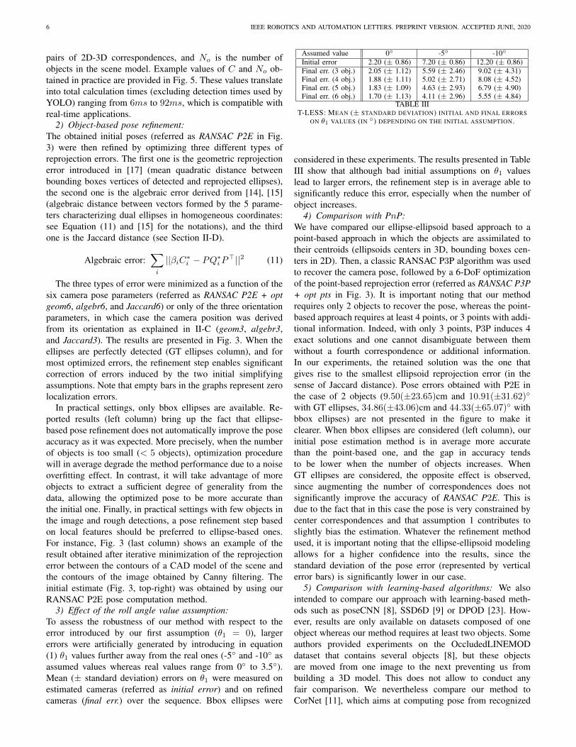
pairs of 2D-3D correspondences, and No is the number ofobjects in the scene model. Example values of C and No ob-tained in practice are provided in Fig. 5. These values translateinto total calculation times (excluding detection times used byYOLO) ranging from 6ms to 92ms, which is compatible withreal-time applications.
2) Object-based pose refinement:The obtained initial poses (referred as RANSAC P2E in Fig.3) were then refined by optimizing three different types ofreprojection errors. The first one is the geometric reprojectionerror introduced in [17] (mean quadratic distance betweenbounding boxes vertices of detected and reprojected ellipses),the second one is the algebraic error derived from [14], [15](algebraic distance between vectors formed by the 5 parame-ters characterizing dual ellipses in homogeneous coordinates:see Equation (11) and [15] for the notations), and the thirdone is the Jaccard distance (see Section II-D).
Algebraic error:∑i
||βiC∗i − PQ∗iP>||2 (11)
The three types of error were minimized as a function of thesix camera pose parameters (referred as RANSAC P2E + optgeom6, algebr6, and Jaccard6) or only of the three orientationparameters, in which case the camera position was derivedfrom its orientation as explained in II-C (geom3, algebr3,and Jaccard3). The results are presented in Fig. 3. When theellipses are perfectly detected (GT ellipses column), and formost optimized errors, the refinement step enables significantcorrection of errors induced by the two initial simplifyingassumptions. Note that empty bars in the graphs represent zerolocalization errors.
In practical settings, only bbox ellipses are available. Re-ported results (left column) bring up the fact that ellipse-based pose refinement does not automatically improve the poseaccuracy as it was expected. More precisely, when the numberof objects is too small (< 5 objects), optimization procedurewill in average degrade the method performance due to a noiseoverfitting effect. In contrast, it will take advantage of moreobjects to extract a sufficient degree of generality from thedata, allowing the optimized pose to be more accurate thanthe initial one. Finally, in practical settings with few objects inthe image and rough detections, a pose refinement step basedon local features should be preferred to ellipse-based ones.For instance, Fig. 3 (last column) shows an example of theresult obtained after iterative minimization of the reprojectionerror between the contours of a CAD model of the scene andthe contours of the image obtained by Canny filtering. Theinitial estimate (Fig. 3, top-right) was obtained by using ourRANSAC P2E pose computation method.
3) Effect of the roll angle value assumption:To assess the robustness of our method with respect to theerror introduced by our first assumption (θ1 = 0), largererrors were artificially generated by introducing in equation(1) θ1 values further away from the real ones (-5◦ and -10◦ asassumed values whereas real values range from 0◦ to 3.5◦).Mean (± standard deviation) errors on θ1 were measured onestimated cameras (referred as initial error) and on refinedcameras (final err.) over the sequence. Bbox ellipses were
TABLE IIIT-LESS: MEAN (± STANDARD DEVIATION) INITIAL AND FINAL ERRORS
ON θ1 VALUES (IN ◦) DEPENDING ON THE INITIAL ASSUMPTION.
considered in these experiments. The results presented in TableIII show that although bad initial assumptions on θ1 valueslead to larger errors, the refinement step is in average able tosignificantly reduce this error, especially when the number ofobject increases.
4) Comparison with PnP:We have compared our ellipse-ellipsoid based approach to apoint-based approach in which the objects are assimilated totheir centroids (ellipsoids centers in 3D, bounding boxes cen-ters in 2D). Then, a classic RANSAC P3P algorithm was usedto recover the camera pose, followed by a 6-DoF optimizationof the point-based reprojection error (referred as RANSAC P3P+ opt pts in Fig. 3). It is important noting that our methodrequires only 2 objects to recover the pose, whereas the point-based approach requires at least 4 points, or 3 points with addi-tional information. Indeed, with only 3 points, P3P induces 4exact solutions and one cannot disambiguate between themwithout a fourth correspondence or additional information.In our experiments, the retained solution was the one thatgives rise to the smallest ellipsoid reprojection error (in thesense of Jaccard distance). Pose errors obtained with P2E inthe case of 2 objects (9.50(±23.65)cm and 10.91(±31.62)◦with GT ellipses, 34.86(±43.06)cm and 44.33(±65.07)◦ withbbox ellipses) are not presented in the figure to make itclearer. When bbox ellipses are considered (left column), ourinitial pose estimation method is in average more accuratethan the point-based one, and the gap in accuracy tendsto be lower when the number of objects increases. WhenGT ellipses are considered, the opposite effect is observed,since augmenting the number of correspondences does notsignificantly improve the accuracy of RANSAC P2E. This isdue to the fact that in this case the pose is very constrained bycenter correspondences and that assumption 1 contributes toslightly bias the estimation. Whatever the refinement methodused, it is important noting that the ellipse-ellipsoid modelingallows for a higher confidence into the results, since thestandard deviation of the pose error (represented by verticalerror bars) is significantly lower in our case.
5) Comparison with learning-based algorithms: We alsointended to compare our approach with learning-based meth-ods such as poseCNN [8], SSD6D [9] or DPOD [23]. How-ever, results are only available on datasets composed of oneobject whereas our method requires at least two objects. Someauthors provided experiments on the OccludedLINEMODdataset that contains several objects [8], but these objectsare moved from one image to the next preventing us frombuilding a 3D model. This does not allow to conduct anyfair comparison. We nevertheless compare our method toCorNet [11], which aims at computing pose from recognized
GAUDILLIERE et al.: PERSPECTIVE-2-ELLIPSOID 7
bbox ellipses GT ellipses
Fig. 3. Refinement issues on the T-LESS dataset. Mean (with standard deviation) position and orientation errors before and after refinement with bbox ellipses(left) and GT ellipses (middle). Right: Pose refinement based on contour registration. Top: Perspective projection of a CAD model of the scene based onRANSAC P2E. Bottom: Pose refinement by iterative minimization of the reprojection error of the model edges.
generic 3D corners without specific scene retraining. Resultsare available on object 20 from scene 08 (T-LESS). For corNet,no solution with an IOU larger than .8 is available whereaswe obtain a succes rate which goes from 66% (pose from 2objects) to 98.6% (6 objects). Only 34% of success rate isobtained by CorNet with a lower requirement of 0.4, whereasours ranges from 95.0% to 100%. Considering the 3D metricADD, our pose from 2 objects is as accurate as CorNet,whereas our accuracy is much higher with more objects.
B. Freiburg Dataset experiments
The Freiburg Dataset [22] provides large and realistic en-vironments that exhibit several objects of interest, makingthis dataset suitable for assessing the efficiency of object-based camera pose estimation methods. In our experiments,we consider a subset of 788 cameras from the Freiburg2/desksequence. These images have been selected such that at leastthree objects are detected by YOLO [7] in each of them.Ellipsoidal models of objects were first built off-line froma dozen of images picked among the 2965 images of thesequence, using the method described in [15]. By contrastwith T-LESS experiments (Section IV-A), the 2D-3D dataassociations are not known. However, YOLO labels weretransferred to 3D ellipsoids during model building and, at testtime, we use our extended RANSAC-like procedure presentedin Section III-A to associate 2D and 3D data as well as toestimate the camera pose. Results are presented in Fig. 4, incomparison with the point-based approach already describedin Section IV-A4.
Considering the RANSAC P3P, a small distance thresholdleads to discard most images (less than 4 inliers), but givesaccurate results on 75% of images when the method succeeds,whereas a large threshold enables to compute a pose for a largeproportion of images, but at the price of lower accuracy. On
0 5 10 15 20 25 30
Orientation error (°)
0
0.1
0.2
0.3
0.4
0.5
0.6
0.7
0.8
0.9
1
Ours (100%)
PnP 3 (41.8%)
PnP 5 (55.6%)
PnP 7 (62.6%)
PnP 10 (73.3%)
PnP 20 (95.2%)
PnP 30 (97.7%)
0 5 10 15 20 25 30 35 40
Position error (cm)
0
0.1
0.2
0.3
0.4
0.5
0.6
0.7
0.8
0.9
1
Ours
PnP 3
PnP 5
PnP 7
PnP 10
PnP 20
PnP 30
Fig. 4. Freiburg: Cumulative density functions of orientation and positionerrors in comparison with PnP. PnP X refers to the thresholdX (in pixels) usedto discriminate between inliers and outliers. For each method, percentagesindicate the proportion of images with successful pose computation.
the contrary, our parameter-free method was able to processall images and provides the most accurate results: 4.76◦ (±3.40◦) in average in orientation, and 12.26cm (± 8.19cm) inaverage in position, over the 788 images. The lower level ofperformance here in comparison with the T-LESS experimentscomes from the fact that the bounding boxes detected byYOLO often suffer from important noise and/or occlusions.
Figure 5 shows several typical situations with which ourmethod can be confronted. At the bottom of each case aregiven information about the RANSAC input data and thelocalization error. Case 1 is an easy case in that a large numberof objects were detected and correctly classified. Our methodobviously obtains a good accuracy in such situations. In case2, only 3 objects have been detected. This corresponds tothe minimum number of objects needed to be robust to oneclassification error and to be able to disambiguate betweenmultiple matching hypotheses. Object labeling is correct incase 2, but two cups and two bowls are instantiated inthe model, which is well addressed here. Case 3 is morechallenging: four objects have been detected but two of them
(1) C:20, Nin:5 (6.4cm, 4.1◦) (2) C:21, Nin:3 (15.4cm, 3.6◦) (3) C:29, Nin:4 (21.1cm, 4.4◦) (4) C:2, Nin:2 (15.4cm, 7.6◦) (5) C:3, Nin:2 (263.0cm, 151.3◦)error on Θ2 = 1.0◦ error on Θ2 = 2.3◦ error on Θ2 = 1.7◦ error on Θ2 = 6.1◦ error on Θ2 = 45.3◦
Fig. 5. Example of typical situations with which our method can be confronted. First row: detection boxes obtained by YOLO. Second row: projected 3Dmodel after RANSAC P2E. Ellipsoids classified as inliers are drawn in green, others in black. Last rows: number of matching hypotheses C, number of inliersNin and localization errors (translation, rotation) for each case, then errors made on Θ2 angles. The scene model consists of No = 16 ellipsoids in all theseexperiments.
appear several times in the model (the cup and the book),three have a shape far from that of an ellipsoid (the book,the Teddy bear, and especially the plant), and finally two arepartially outside the image boundaries. Despite this, the poseaccuracy remains reasonable, thanks to the fairly high numberof detections. Case 4 is even more difficult since only twoobjects were detected. Moreover, their shape is far from thatof an ellipsoid and they partially fall out of the image. The boxcorresponding to the plant is also particularly disproportionate.Although pose accuracy suffers slightly (see the orientationerror), it is not aberrant. What helped here is the fact thatthese two objects have been correctly classified and appearonly once in the model. Case 5, however, makes our methodfail: in this truncated view of the scene, only two objects havebeen detected, including a false positive (the corner of the deskis detected as a book). Among the three books in the model,one is arbitrarily chosen, which results in an aberrant pose.
V. CONCLUSION
In this paper, we have presented a novel object-basedpose estimation method relying on two weak simplifyingassumptions. Pose estimation is thus turned into a 1-DoFproblem, solved using exhaustive search over the unknownparameter. A factor limiting the accuracy of our method isthe ellipse detection process, that makes our method based onvery coarse ellipses. This procedure will be reconsidered inour future work. Moreover, we have shown that our methodis capable of processing scenes with few objects. A strategywill be developed to jointly take advantage of this capabilityand the benefits of the PnP approach with more objects.
REFERENCES
[1] E. Marchand, H. Uchiyama, and F. Spindler, “Pose estimation foraugmented reality: A hands-on survey,” IEEE TVCG, 2016.
[2] L. Kneip, D. Scaramuzza, and R. Siegwart, “A novel parametrization ofthe perspective-three-point problem for a direct computation of absolutecamera position and orientation,” in CVPR, 2011.
[3] R. I. Hartley and A. Zisserman, Multiple View Geometry in ComputerVision, 2nd ed. Cambridge University Press, 2004.
[4] V. Lepetit, F. Moreno-Noguer, and P. Fua, “Epnp: An accurate O(n)solution to the pnp problem,” Int. Journal of Computer Vision, 2009.
[5] R. B. Girshick, “Fast R-CNN,” in ICCV, 2015.[6] W. Liu, D. Anguelov, D. Erhan, C. Szegedy, S. E. Reed, C. Fu, and
A. C. Berg, “SSD: single shot multibox detector,” in ECCV, 2016.[7] J. Redmon and A. Farhadi, “Yolov3: An incremental improvement,”
http://arxiv.org/abs/1804.02767, 2018.[8] Y. Xiang, T. Schmidt, V. Narayanan, and D. Fox, “Posecnn: A convolu-
tional neural network for 6d object pose estimation in cluttered scenes,”Robotics: Science and Systems, 2018.
[9] W. Kehl, F. Manhardt, F. Tombari, S. Ilic, and N. Navab, “Ssd-6d:Making rgb-based 3d detection and 6d pose estimation great again,”in ICCV, 2017.
[10] S. Zakharov, I. Shugurov, and S. Ilic, “DPOD: 6d pose object detectorand refiner,” in ICCV, 2019.
[11] G. Pitteri, S. Ilic, and V. Lepetit, “CorNet: Generic 3D Corners for 6DPose Estimation of New Objects without Retraining,” in ICCV Workshopon Recovering 6D Object Pose, 2019.
[12] J. Li, D. Meger, and G. Dudek, “Context-coherent scenes of objects forcamera pose estimation,” in IROS, 2017.
[13] J. Li, Z. Xu, D. Meger, and G. Dudek, “Semantic scene models forvisual localization under large viewpoint changes,” in CRV, 2018.
[14] M. Crocco, C. Rubino, and A. Del Bue, “Structure from motion withobjects,” in CVPR, 2016.
[15] C. Rubino, M. Crocco, and A. D. Bue, “3d object localisation frommulti-view image detections,” IEEE TPAMI, 2018.
[16] D. P. Frost, O. Kahler, and D. W. Murray, “Object-aware bundleadjustment for correcting monocular scale drift,” in ICRA, 2016.
[17] L. Nicholson, M. Milford, and N. Sunderhauf, “Quadricslam: Dualquadrics from object detections as landmarks in object-oriented slam,”IEEE RA-L, 2019.
[18] V. Gaudilliere, G. Simon, and M.-O. Berger, “Camera Pose Estimationwith Semantic 3D Model,” in IROS, 2019.
[19] ——, “Camera Relocalization with Ellipsoidal Abstraction of Objects,”in ISMAR, 2019.
[20] C. Toft, E. Stenborg, L. Hammarstrand, L. Brynte, M. Pollefeys,T. Sattler, and F. Kahl, “Semantic match consistency for long-term visuallocalization,” in ECCV, 2018.
[21] T. Hodan, P. Haluza, S. Obdrzalek, J. Matas, M. Lourakis, and X. Zabu-lis, “T-LESS: An RGB-D dataset for 6D pose estimation of texture-lessobjects,” WACV, 2017.
[22] J. Sturm, N. Engelhard, F. Endres, W. Burgard, and D. Cremers, “Abenchmark for the evaluation of rgb-d slam systems,” in IROS, 2012.
[23] S. Zakharov, I. Shugurov, and S. Ilic, “Dpod: 6d pose object detectorand refiner,” in ICCV, 2019.