PERSPECTIVE PROJECTION Gopi Meenakshisundaram 1) What does the perspective projection matrix assume? • Eye is at the origin. • View-up vector is along the Y-axis. • View Plane is parallel to the XY plane 2) What does glFrustum (perspective projection) achieve? • View frustum is along the negative Z-axis • The view frustum planes are at 45 degrees from the view frustum axis. In effect, the total angle between the view frustum planes are 90 degrees along X and Y axes. • Find x,y, and z coordinate of any object point on the screen and for correct visibility computation. (Explained in detail later). 3) How do you satisfy the assumptions? (Question 1) The gluLookAt function achieves the first three requirements. It is split into two functions RT. The T (translation) brings eye to the origin. The R (rotation) rotates such that the view-up vector aligns with the Y axis, and the projection plane is parallel to the XY plane. We assume that this transformation is done before projection transformation is computed. So we do not take into account the gluLookAt transformations (RT) as part of projection transformations.
Transcript
PERSPECTIVE PROJECTION
Gopi Meenakshisundaram
1) What does the perspective projection matrix assume?
• Eye is at the origin.• View-up vector is along the Y-axis.• View Plane is parallel to the XY plane
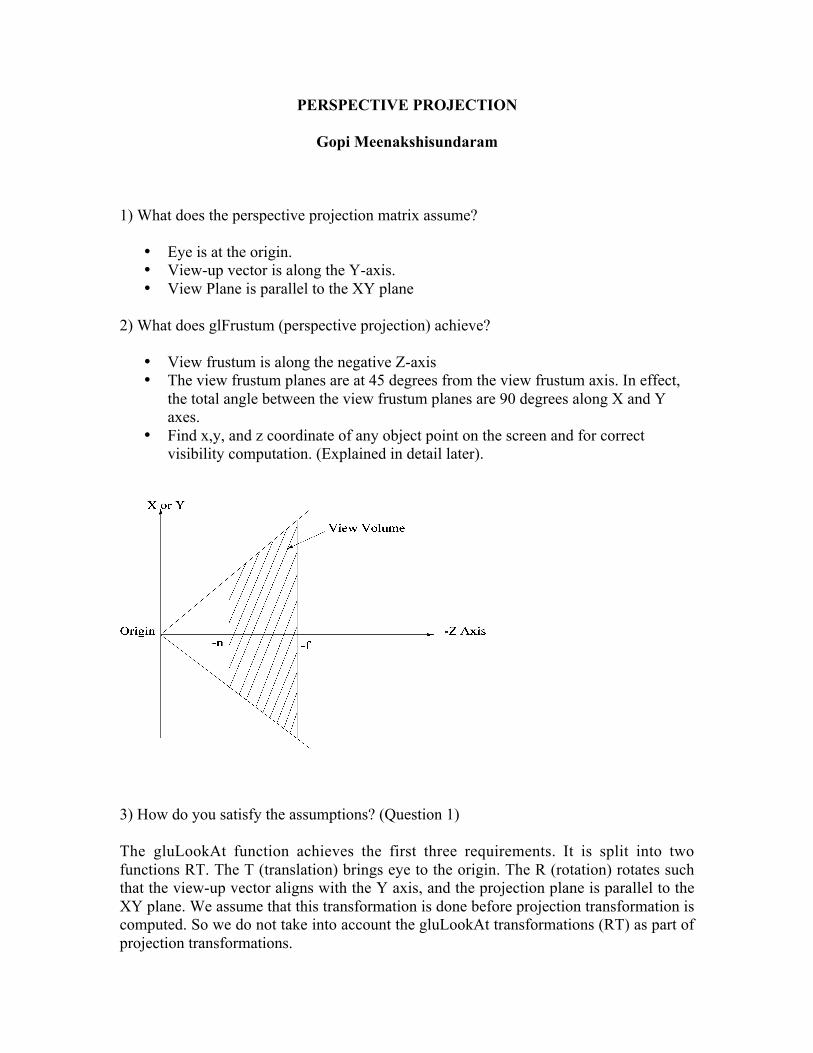
2) What does glFrustum (perspective projection) achieve?
• View frustum is along the negative Z-axis• The view frustum planes are at 45 degrees from the view frustum axis. In effect,
the total angle between the view frustum planes are 90 degrees along X and Yaxes.
• Find x,y, and z coordinate of any object point on the screen and for correctvisibility computation. (Explained in detail later).
3) How do you satisfy the assumptions? (Question 1)
The gluLookAt function achieves the first three requirements. It is split into twofunctions RT. The T (translation) brings eye to the origin. The R (rotation) rotates suchthat the view-up vector aligns with the Y axis, and the projection plane is parallel to theXY plane. We assume that this transformation is done before projection transformation iscomputed. So we do not take into account the gluLookAt transformations (RT) as part ofprojection transformations.
4) How do you do the first transformation required by glFrustum?
By Shear Matrix
†
1 0 r + l2n
0
0 1 t + b2n
00 0 1 00 0 0 1
5) How do you do the second transformation required by glFrustum? (Refer Qusetion 2).
By Scaling
†
2nr - l
0 0 0
0 2nt - b
0 00 0 1 00 0 0 1
Answers to Questions 4 and 5 bring the view frustum similar to the diagram shownearler.
The above two requirements are easy to describe geometrically. The next requirement isbased on the requirement that is not directly related to perspective projection. It isrequired by later stages of the graphics pipeline like rasterization. So we have to jumpahead a bit to describe what is required by the rasterization, and then come back tocompute the appropriate transformation to achieve that.
6) What is the requirement of the rasterization stage?
Rasterization is done on the window. Given the end points of a line, it finds theintermediate pixels that forms the line by linearly interpolating the x,y coordinates of theend points. Similarly, it can fill a triangle, given its three vertices, by bi-linearlyinterpolating the end points. First, the object space 3D coordinates have to be transformed into screen 2Dcoordinates. Since rasterization stage works only in 2D on the screen, it is enough if wetransform the 3D x and y coordinates correctly to 2D x and y screen coordinates. We canignore the Z value. It is like taking a photograph. We don’t care about the depth. We arejust taking a 2D image of the 3D scene.
But unfortunately, unlike photographs, where an object in the front automaticallyoccludes the object in the back, in graphics, we have to find which object is in the frontand which object is in the back to get a correct image. One way to achieve this is to drawthe objects that are in the back first, and then draw objects that are in the front. Thus theobjects in the front will overwrite that are in the back yielding correct visibility. Since thetriangles are drawn in order, again it is enough for the rasterization stage to know onlythe x and y coordinates.
But, unfortunately again, during rasterization, you don’t always get the trianglesin back-to-front order. Triangles come in arbitrary order. You are not allowed to store allthe triangles, compute their back-to-front order, and then draw. So the only way to get thecorrect ordering is to find the correct Z value to figure out which object is in the front andwhich is in the back, as and when it arrives to the rasterization stage. In fact, you have toknow the correct Z value for all points in the triangle, not just at the vertices.
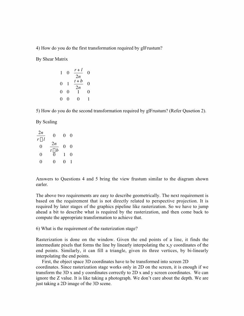
Since we have Z values only for the end points of the triangle or lines, we have tointerpolate this Z to get the correct Z values for pixels in-between. We need the correct Zvalue everywhere for the following reason. Refer to the figure below. If a blue triangleand a green triangle stab each other, we need to draw this intersection line. On one side ofthe intersection line green is visible, and blue is below green, and on the other side, thisrelationship is reversed. We need to know the exact Z coordinates everywhere on thetriangle to resolve this back-to-front ordering and relationship.
This shows that interpolation of Z is required. Remember we are alreadyinterpolating the x any y coordinates, and that too with the same function (linearinterpolation). So the question is, can we use the same linear interpolation function on theZ values also? The answer is NO!
7) Why can’t we do a linear interpolation of Z from the Z values of the end points, as wedo in the cases of X and Y?
To answer this question, we need to know why we interpolate and what is the relationshipbetween the transformation of end points, and the interpolation of intermediate points.
Transforming all points: Ideally, we should consider the triangle (and the objectas a whole) consists of infinite number of 3D points, and we should think that we aretransforming (projecting) all these points to 2D coordinates on the screen. (Thistransformation is a projective transformation that uses similar triangles property:
x’=x/(-z), and y’=y/(-z).Interpolating interior points: Instead we transform only the vertices of the
triangle (or line) and linearly interpolate this projected value to get all projected points. We are saving a lot of time and space by doing just the interpolation instead of
transformation of infinite number of points. On the other hand, we have to show that theinterpolation is same as transformation. In this context we have to know what istransformed and what is not.
There are two kinds of data: the transformed data, and the attributes. The (x’,y’)screen coordinates got by transforming a 3D point, are the transformed data. All otherdata, including the z value, are attributes of this point. Other attributes include color,texture coordinate, normal vector, etc. Unlike x and y, the attributes do not undergo anytransformation. In other words, the x and y coordinates of the 3D point is different fromthose of the projected point. But the attributes of the 3D point are exactly the same as thatof the projected point. For example, the color of the 3D point should not change afterbeing projected to a 2D screen. In the same way, the z value stored with the 2D point asan attribute should be same as the z coordinate of the 3D point. (Remember, for a 2Dprojected point, z value is just another attribute like color, and does not dictate theposition of the point. But the z value for a 3D point is a coordinate and is used to find theposition of that 3D point.)
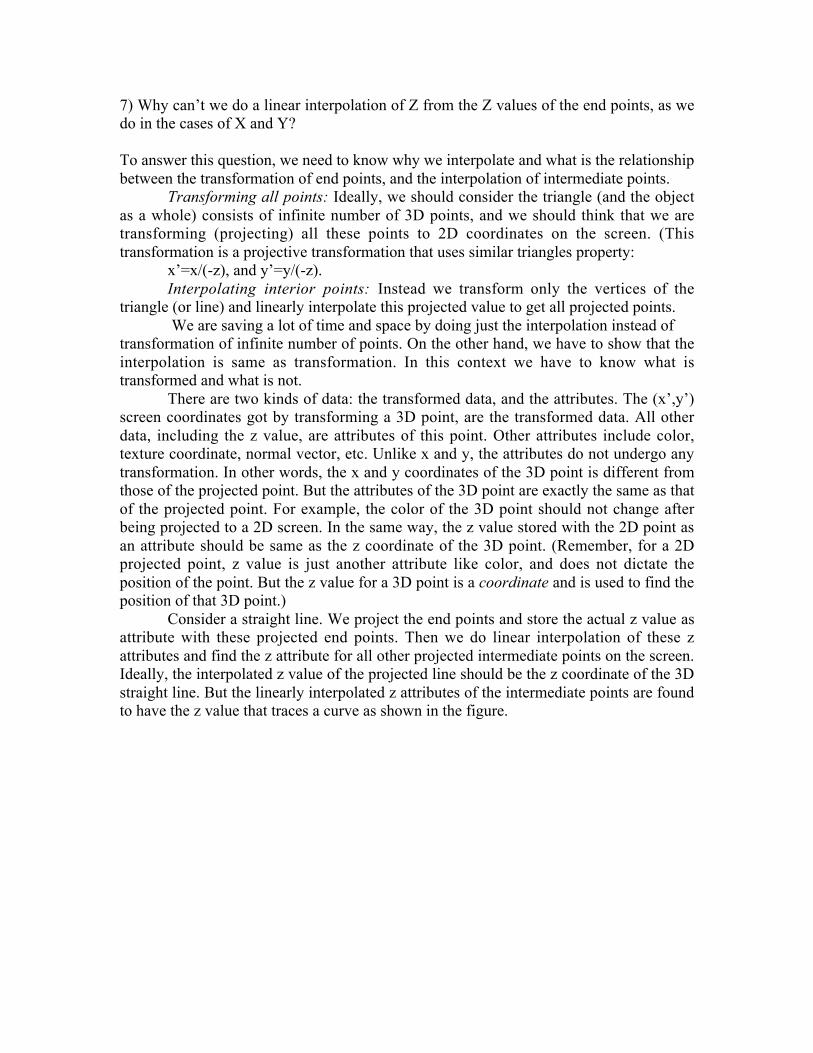
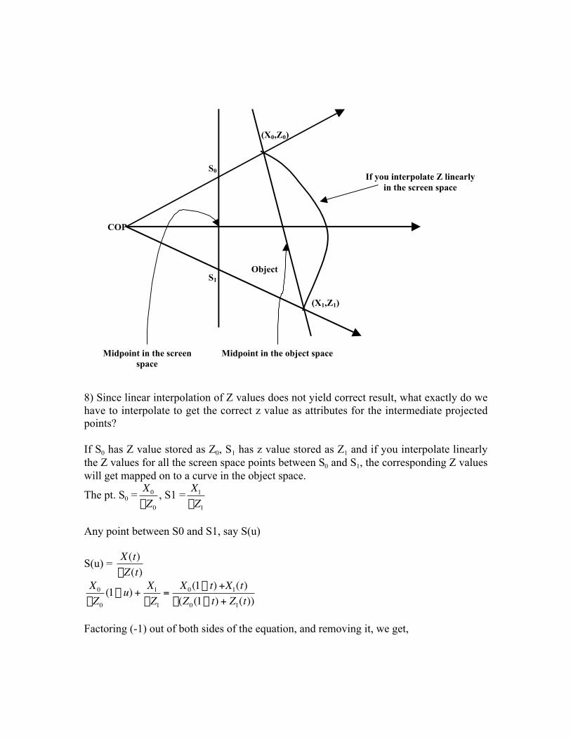
Consider a straight line. We project the end points and store the actual z value asattribute with these projected end points. Then we do linear interpolation of these zattributes and find the z attribute for all other projected intermediate points on the screen.Ideally, the interpolated z value of the projected line should be the z coordinate of the 3Dstraight line. But the linearly interpolated z attributes of the intermediate points are foundto have the z value that traces a curve as shown in the figure.
8) Since linear interpolation of Z values does not yield correct result, what exactly do wehave to interpolate to get the correct z value as attributes for the intermediate projectedpoints?
If S0 has Z value stored as Z0, S1 has z value stored as Z1 and if you interpolate linearlythe Z values for all the screen space points between S0 and S1, the corresponding Z valueswill get mapped on to a curve in the object space.
The pt. S0 =
†
X0
-Z0
, S1 =
†
X1
-Z1
Any point between S0 and S1, say S(u)
S(u) =
†
X(t)-Z(t)
†
X0
-Z0
(1- u) +X1
-Z1
=X0(1- t) +X1(t)
-(Z0(1- t) + Z1(t))
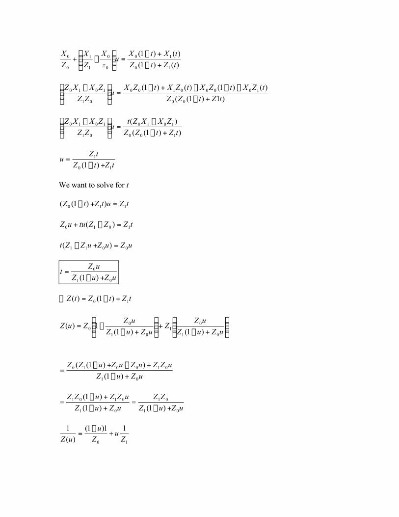
Factoring (-1) out of both sides of the equation, and removing it, we get,
(X0,Z0)
COP
S0
S1
(X1,Z1)
Object
Midpoint in the screenspace
Midpoint in the object space
If you interpolate Z linearlyin the screen space
)()1(
)()1(
10
10
0
0
1
1
0
0
tZtZ
tXtXu
z
X
Z
X
Z
X
+-
+-=˜̃
¯
ˆÁÁË
Ê-+
)1)1((
)()1()()1(
00
10000100
01
1010
tZtZZ
tZXtZXtZXtZXu
ZZ
ZXXZ
+-
---+-=˜̃
¯
ˆÁÁË
Ê -
))1((
)(
100
1010
01
1010
tZtZZ
ZXXZtu
ZZ
ZXXZ
+-
-=˜̃
¯
ˆÁÁË
Ê -
tZtZ
tZu
10
1
)1( +-=
We want to solve for t
tZutZtZ 110 ))1(( =+-
tZZZtuuZ 1010 )( =-+
uZuZuZZt 0011 )( =+-
uZuZ
uZt
01
0
)1( +-=
tZtZtZ 10 )1()( +-=\
˜̃¯
ˆÁÁË
Ê
+-+˜̃
¯
ˆÁÁË
Ê
+--=
uZuZ
uZZ
uZuZ
uZZuZ
01
01
01
00 )1()1(
1)(
uZuZ
uZZuZuZuZZ
01
010010
)1(
))1((
+-
+-+-=
uZuZ
ZZ
uZuZ
uZZuZZ
01
01
01
0101
)1()1(
)1(
+-=
+-
+-=
10
11)1(
)(
1
Zu
Z
u
uZ+
-=
So the actual Z of the interpolated points is computed by linearly interpolating Z
1 and
taking the reciprocal of the interpolated value.
Similar to Z interpolation, other attributes like color and texture coordinates have to beinterpolated in the above way. But, very rarely one does color interpolation by linearlyinterpolating the reciprocal. Since humans are not very sensitive to minor color changes,most systems cheat by linearly interpolating the color instead of linearly interpolating thereciprocal of the color values. On the other hand, no one cheats on interpolating thetexture coordinates.
As part of efficient and correct computation of interpolation, a function of
†
1Z
is stored at
the vertices and the depth buffer, instead of Z. Another reason for using
†
1Z
instead of Z is
to get more resolution for objects that are close to near plane (closer Z) and lessresolution for objects that are far (close to the far plane). Further, now, you can set thefar plane to -infinity and just store zero for –1/f. For the same reason, you should neverset the near plane to 0 (origin).
9) What function of Z
1 is stored in the depth buffer?
The values of Z
1 range from
n-
1 to
f-
1. This range is scaled between +1 and -1. This is
what is stored at the vertices and depth buffer.
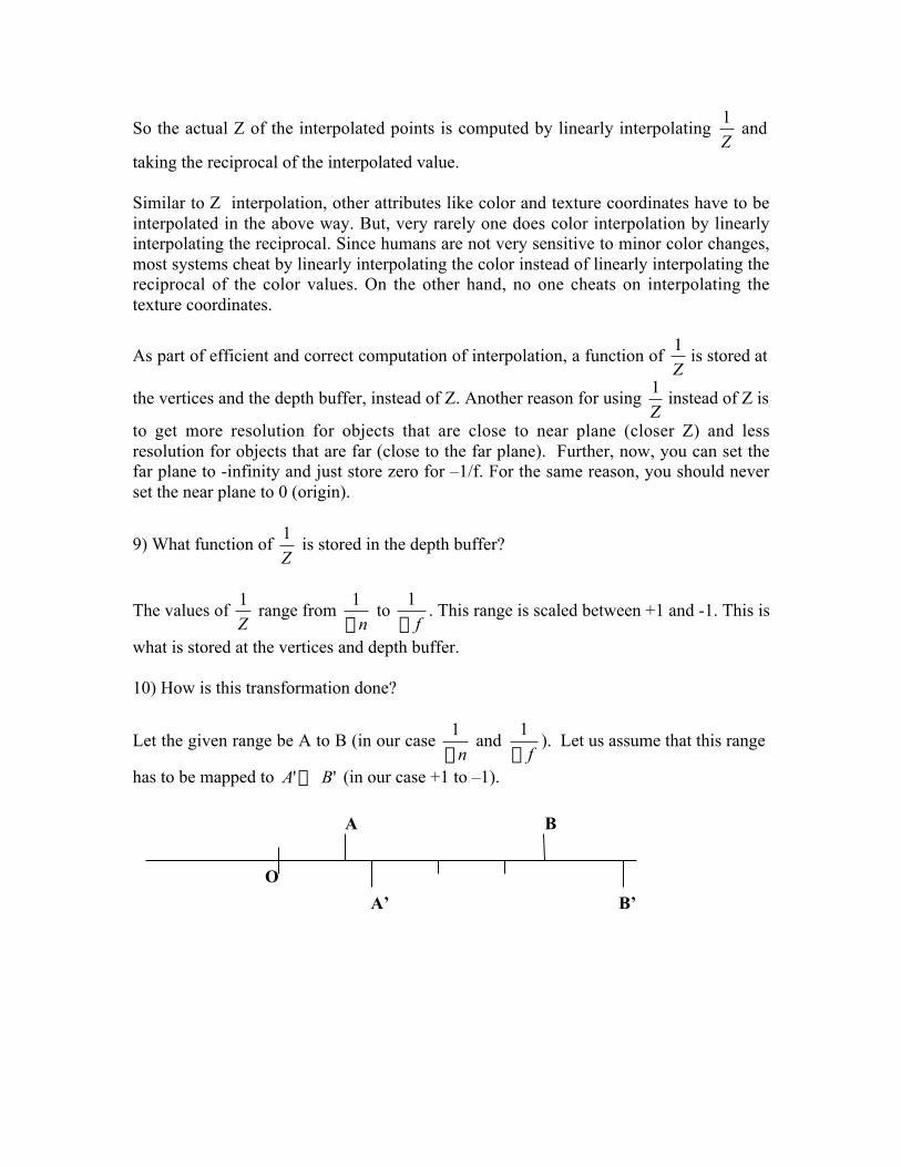
10) How is this transformation done?
Let the given range be A to B (in our case n-
1 and
f-
1). Let us assume that this range
has to be mapped to '' BA ´ (in our case +1 to –1).
O
A
A’
B
B’
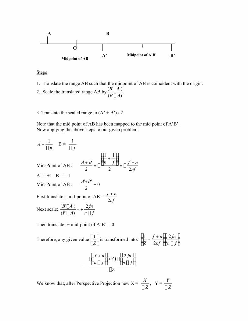
Steps
1. Translate the range AB such that the midpoint of AB is coincident with the origin.
2. Scale the translated range AB by
†
(B'-A')(B - A)
.
3. Translate the scaled range to (A’ + B’) / 2
Note that the mid point of AB has been mapped to the mid point of A’B’.Now applying the above steps to our given problem:
nA
-=
1 B =
f-
1
Mid-Point of AB : nf
nffnBA
22
11
2
+-=
˜̃¯
ˆÁÁË
Ê+
-=+
A’ = +1 B’ = -1
Mid-Point of AB : 02
''=
+BA
First translate: -mid-point of AB =
†
f + n2nf
Next scale:
†
(B'-A')(B - A)
= +2 fn
n - f
Then translate: + mid-point of A’B’ = 0
Therefore, any given value
†
1Z
Ê
Ë Á
ˆ
¯ ˜ is transformed into:
†
1Z
+f + n2nf
Ê
Ë Á
ˆ
¯ ˜
2 fnn - f
Ê
Ë Á
ˆ
¯ ˜
=
†
-f + nn - f
Ê
Ë Á
ˆ
¯ ˜ +Z( ) -
2 fnn - f
Ê
Ë Á
ˆ
¯ ˜
-Z
We know that, after Perspective Projection new X = Z
X
-, Y =
Z
Y
-
O
A
A’
B
B’Midpoint of AB
Midpoint of A’B’
The homogeneous point, (x,y,z,w) is same as the homogeneous point (x/w, y/w, z/w, 1).Therefore, the homogeneous point after the perspective transformation is:
†
X,Y, f + nf - n
Z( ) +2 fnf - n
,-ZÊ
Ë Á
ˆ
¯ ˜
So, the matrix for perspective transformation, that transforms a point (X,Y,Z, 1) to theabove perspectively transformed point is given by:
†
1 0 0 00 1 0 00 0 f + n
f - n2 fnf - n
0 0 -1 0
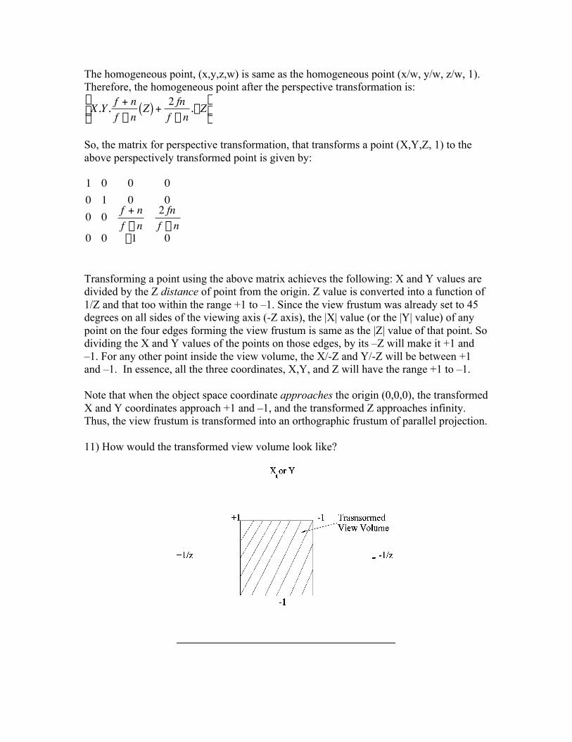
Transforming a point using the above matrix achieves the following: X and Y values aredivided by the Z distance of point from the origin. Z value is converted into a function of1/Z and that too within the range +1 to –1. Since the view frustum was already set to 45degrees on all sides of the viewing axis (-Z axis), the |X| value (or the |Y| value) of anypoint on the four edges forming the view frustum is same as the |Z| value of that point. Sodividing the X and Y values of the points on those edges, by its –Z will make it +1 and–1. For any other point inside the view volume, the X/-Z and Y/-Z will be between +1and –1. In essence, all the three coordinates, X,Y, and Z will have the range +1 to –1.
Note that when the object space coordinate approaches the origin (0,0,0), the transformedX and Y coordinates approach +1 and –1, and the transformed Z approaches infinity.Thus, the view frustum is transformed into an orthographic frustum of parallel projection.
11) How would the transformed view volume look like?
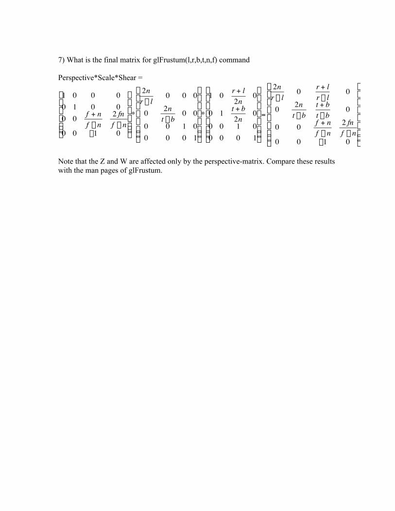
7) What is the final matrix for glFrustum(l,r,b,t,n,f) command
Perspective*Scale*Shear =
†
1 0 0 00 1 0 00 0 f + n
f - n2 fnf - n
0 0 -1 0
Ê
Ë
Á Á Á Á Á
ˆ
¯
˜ ˜ ˜ ˜ ˜
*
2nr - l
0 0 0
0 2nt - b
0 00 0 1 00 0 0 1
Ê
Ë
Á Á Á Á Á Á
ˆ
¯
˜ ˜ ˜ ˜ ˜ ˜
*
1 0 r + l2n
0
0 1 t + b2n
00 0 1 00 0 0 1
Ê
Ë
Á Á Á Á Á Á
ˆ
¯
˜ ˜ ˜ ˜ ˜ ˜
=
2nr - l
0 r + lr - l
0
0 2nt - b
t + bt - b
0
0 0 f + nf - n
2 fnf - n
0 0 -1 0
Ê
Ë
Á Á Á Á Á Á Á
ˆ
¯
˜ ˜ ˜ ˜ ˜ ˜ ˜
Note that the Z and W are affected only by the perspective-matrix. Compare these resultswith the man pages of glFrustum.