36
1 PETE 411 Well Drilling Lesson 3 The Rig - Drilling Equipment
1
PETE 411 Well Drilling
Lesson 3
The Rig - Drilling Equipment

2
Contents Rig Pumps Solids Control Equipment Air Drilling The Rotary System The Swivel The Well Control System The Well Monitoring System Offshore Drilling

3
Assignments:
READ: ADE Ch. 1, to p.30
HW #1: ADE 1.1, 1.2, 1.3 Due Monday, Sept. 9, 2002
at the beginning of class
NOTE: Answers in book are not always correct...
4
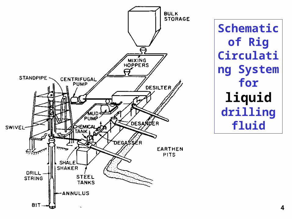
Schematic of Rig
Circulating System for
liquid drilling fluid

5

6
Example 1.3
Compute the pump factor in units of barrels per stroke for a double-acting duplex pump having:
6.5-inch liners (dL)
2.5 inch rods (dr)
18-inch strokes (LS)
and a volumetric efficiency of 90%. (EV)

7
Solution:The pump factor for a duplex pump can be determined using Equation 1.10
stroke/in 1991
5.25.629.0182
dd2EL2
F
3
22
2r
2LVSp

8
Recall:There are 231 in.3 in an U. S. gallon and 42 U.S. gallons in a U.S. barrel. Thus converting to the desired field units yields:
1991 in.3/stroke * gal/231 in.3 * bbl/42 gal.= 0.2052 bbl/stroke.
Thus: Pump Factor = 0.2052 bbl/stroke
9
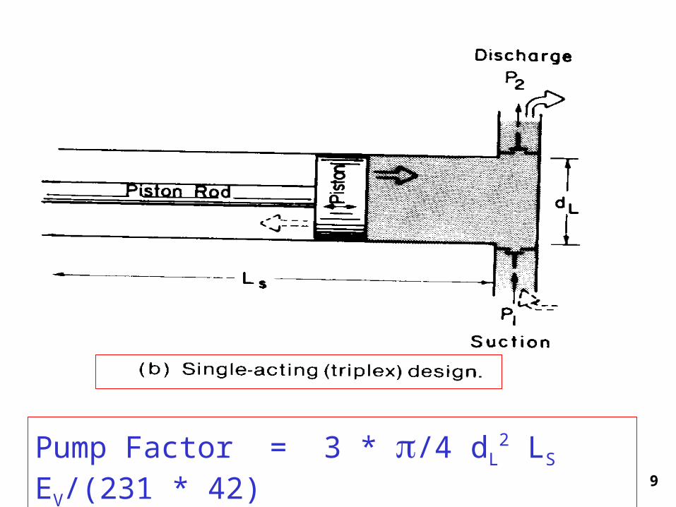
Pump Factor = 3 * /4 dL2 LS EV/(231 * 42)
10
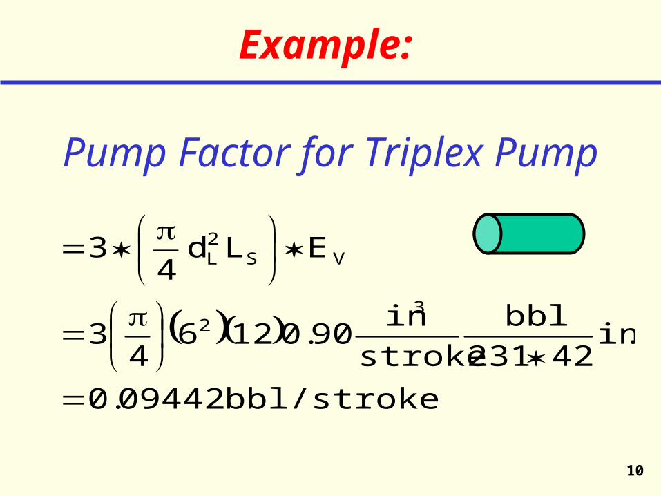
Example:
Pump Factor for Triplex Pump
bbl/stroke 09442.0
.in42231
bblstroke
in90.01264
3
ELd 4
3
32
VS 2
L

11
Example: Pump Rate
= Pump Factor * Strokes/min
= 0.09442
= 7.554 bbl/min= 317.3 gal/min
minstks80
stkbbl
Pump Rate = 317 gal/min

12
Hydrocyclone• desander• desilter
* No moving parts* Low cost* Pressure drop
* Diameter
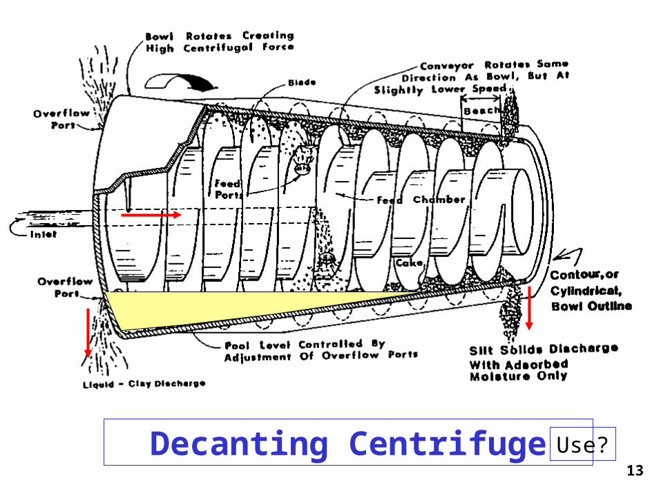
13 Decanting Centrifuge Use?

14
l
l
Use?

15
Fig. 1.33 Schematic of Rotary System

16
Fig. 1.34 Cutaway View of Swivel
ROTATING* Seals* Bearings

17
Fig. 1.38 Cutaway View and
Dimensions for Example Tool Joint
PINBOX
TJShoulder

18
Fig. 1.39 Stabilizer
* Keeps pipe in center of hole* Aids in drilling straight hole* Prolongs bit life
19
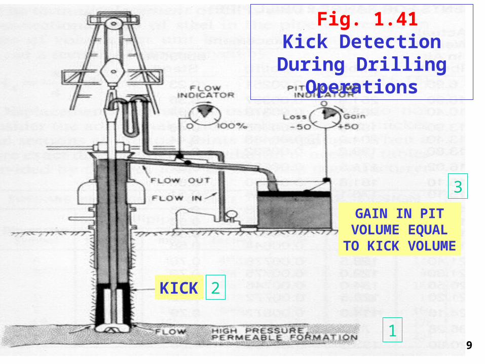
Fig. 1.41 Kick Detection During Drilling
Operations
1
2
3
KICK
GAIN IN PITVOLUME EQUAL
TO KICK VOLUME

20
Fig. 1.46 Remote Control
Panel for operating Blowout
Preventers CHOKE
What to do if KICK occurs?

21Fig. 1.44 Annular Blowout Preventer
DPTJDCOH
Press

22Ram Blowout Preventer

23Ram Blowout Preventer - cont’d
SHEAR / BLINDRAM ASSEMBLY

24Fig. 1.48 Rotating Blowout Preventer
25
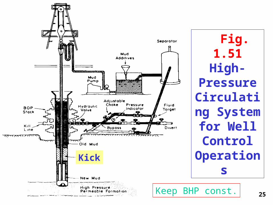
Fig. 1.51 High-
Pressure Circulating System for
Well Control
Operations
Keep BHP const.
Kick

26
Fig. 1.56 Subsurface
Well Monitoring
System
MWD
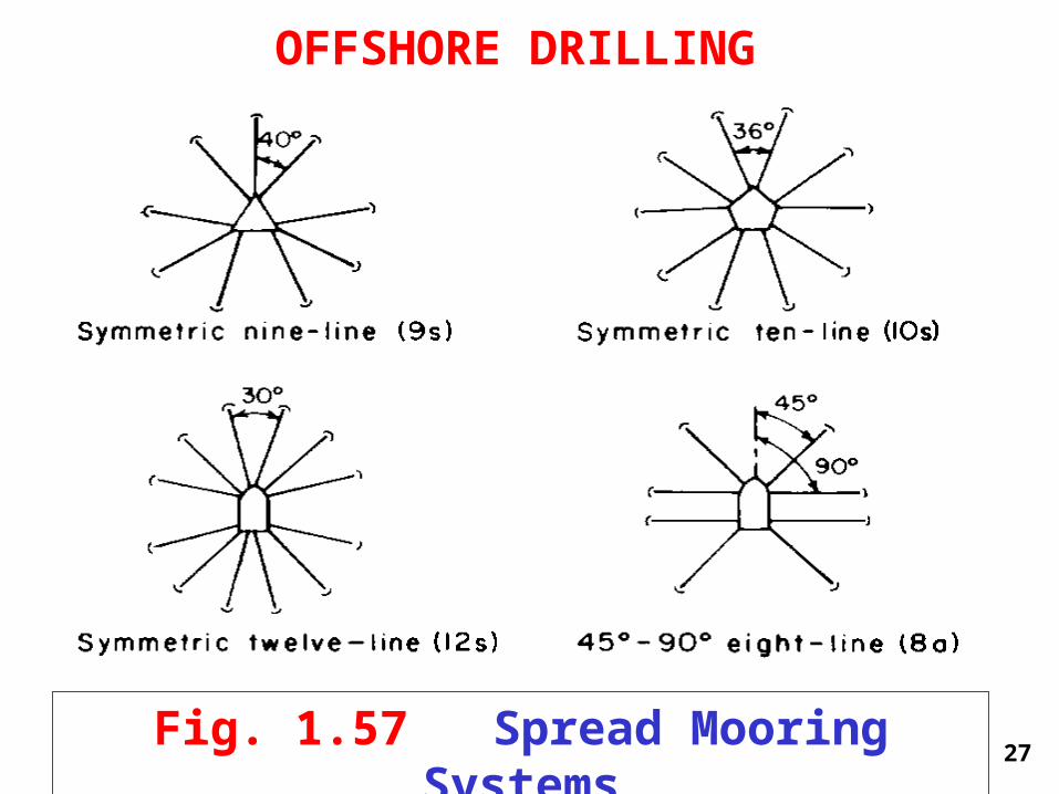
27Fig. 1.57 Spread Mooring Systems
OFFSHORE DRILLING

28
Fig. 1.58 Schematic of Equipment for Marine Drilling
29
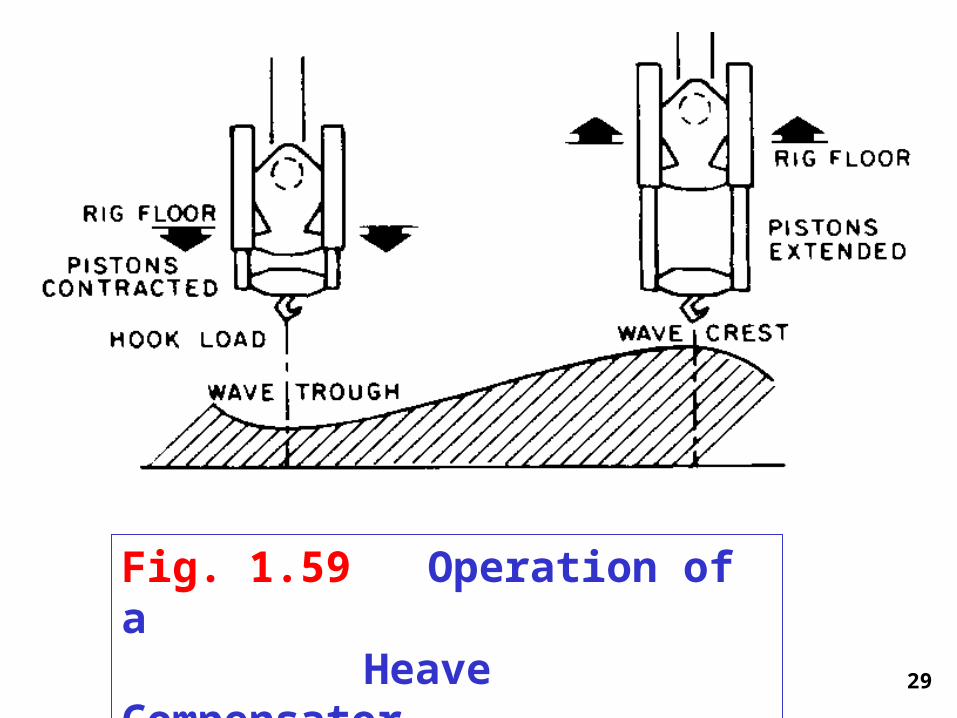
Fig. 1.59 Operation of a Heave Compensator

30
Fig. 1.60 Subsea
BOP Stack

31
Fig. 1.63 Subsea Equipment Installation Procedure

32
Typical Casing Strings
Water Level Depth
Seafloor Below ML
Conductor pile 36” 30” 200’
Conductor Casing 26” 20” 1000’
Surface Casing 17 1/2” 13 3/8” 4000’
Hole Csg. Depth

33
Some Typical Casing Strings
Depth Below
ML
Conductor pile 36” 30” 200’
Conductor Casing 26” 20” 1000’
Surface Casing 17 1/2” 13 3/8” 4000’
Hole Csg. Depth

34Capacity = Area * Length

35
What is the capacity of 10,000 ft of 5” OD, 19.50 lb/ft drillpipe?
Capacity = Area * Length
Area = /4 d2 = /4 * 4.2762 = 14.36 in2
Length = 10,000 ft = 120,000 in
Capacity = 14.36 *120,000 in3 /(231*42 in3 /bbl)
Capacity = 177.6 bbls
36
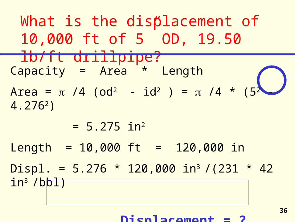
What is the displacement of 10,000 ft of 5” OD, 19.50 lb/ft drillpipe?
Capacity = Area * Length
Area = /4 (od2 - id2 ) = /4 * (52 - 4.2762)
= 5.275 in2
Length = 10,000 ft = 120,000 in
Displ. = 5.276 * 120,000 in3 /(231 * 42 in3 /bbl)
Displacement = ? Bbls


