This work contains the confidential and proprietary trade secrets of Schlumberger and may not be copied or stored in an information retrieval system, transferred, used, distributed, translated or retransmitted in any form or by any means, electronic or mechanical, in whole or in part, without the express written permission of the copyright owner.
Trademarks & Service Marks
Schlumberger, the Schlumberger logotype, and other words or symbols used to identify the products and services described herein are eithertrademarks, trade names or service marks of Schlumberger and its licensors, or are the property of their respective owners. These marks may not be copied, imitated or used, in whole or in part, without the express prior written permission of Schlumberger. In addition, covers, page headers, custom graphics, icons, and other design elements may be service marks, trademarks, and/or trade dress of Schlumberger, and may not be copied, imitated, or used, in whole or in part, without the express prior written permission of Schlumberger. Other company, product, and service names are the properties of their respective owners.
An asterisk (*) is used throughout this online help to designate a mark of Schlumberger.
Petrel seismic to simulation software helps increase reservoir performance by improving asset team productivity. Geophysicists, geologists, and reservoir engineers can develop collaborative workflows and integrate operations to streamline processes.
Benefits
Unify workflows for E&P teams - Eliminate the gaps in traditional systems that require handoffs from one technical domain to the next using Petrel model-centric workflows in a shared earth model.
Manage risk and uncertainty - Easily test multiple scenarios, analyze risk and uncertainty, capture data relationships and parameters to perform rapid updates as new data arrives, and perform detailed simulation history matching.
Enable knowledge management and best practices - Reduce workflow learning curves by capturing best practices via the Workflow Editor, providing quick access to preferred workflows and increasing ease of use through intuitive and repeatable workflows.
Accelerate innovative software development - Seamlessly integrate your intellectual property into the Petrel workflow through the open Ocean framework. This environment leverages .NET tools and offers stable, user-friendly interfaces for efficient development, allowing focus oninnovation rather than infrastructure.
Petrel Geology and Geological Modeling
Petrel Geology and Geological Modeling
Page 1 of 59***
11/5/2013file:///C:/Users/juan/AppData/Local/Temp/~hh26B3.htmPlease purchase 'docPrint PDF Driver' on http://www.verypdf.com/artprint/index.html to remove this message.
With your reservoir model in place, use the Petrel simulation workflow to perform streamline simulation, reduce uncertainty and assist in future well planning.
Uncertainty Analysis and Optimization Workflow | Petrel Well Path Design | Petrel Advanced Gridding and Upscaling | FrontSim | Petrel History Match Analysis | Petrel Reservoir Engineering Core |
Studio
Studio
Improve your Petrel productivity with enhanced data access and point-to-point session sharing.
Petrel Drilling
Petrel Drilling
Well path design, drilling visualization, and real-time model updates
Petrel Well Path Design | Drilling Visualization for Petrel | Real-Time Data Link
Petrel 2011 affords powerful new science, workflow productivity, and enhanced collaboration. Revolutionary new tools help geoscientists and engineers deliver confident decisions—prospect selections, reserves estimates, and well placements—even in challenging environments, where quantifying and managing risk are critical in determining economic success or failure.
Deliver confident prospect selections
� Assess seal capacity and charge timing as you interpret seismic, make maps, and calculate volumes � Capture prospect uncertainty from the start � Get better results faster with new and improved interpretation tools: automatic fault tracking, 3D seismic flattening, and additional modes
for tailed interpretation � Experience a step change in spatial accuracy with a patent-pending positioning and visualization method when moving or merging well and
3D seismic data � Identify stratigraphic traps using the new attribute player combined with geobody isolation capabilities � Leverage new Ocean plug-ins from WesternGeco for prestack interpretation capabilities
Deliver confident reserves estimates
� Test the limits of all your key parameters; accurately assess structural integrity, stratigraphic features, fluid contacts, and propertydistributions
� View and interact with 2D well data, including raster logs with seismic fences and grid model objects, in the new flexible well sectionwindow
� Use new stair-step gridding to correctly model even the most complex faulted reservoirs for a robust sealed structural framework that isoptimal for property population and fluid flow simulation
� Perform local model updates with new well data, properties, and markers to preserve history match for existing wells
Deliver confident well placement
Page 2 of 59***
11/5/2013file:///C:/Users/juan/AppData/Local/Temp/~hh26B3.htmPlease purchase 'docPrint PDF Driver' on http://www.verypdf.com/artprint/index.html to remove this message.
� Evaluate reservoir quality and heterogeneity; model and simulate horizontal wells, multilateral wells, and intelligent completions� Achieve faster history matching—evaluate parameter sensitivity, optimize simulation input, and use local model updates to work directly on
problem areas and run new scenarios to better match production history � Take advantage of property modeling advances—honor target fractions for multipoint facies simulation � Handle large and complex fields with the fast performance and scalability of the INTERSECT next-generation simulator, which uses novel
numerical techniques for non-uniform and unstructured grids
Revolutionize the way you work with the new Studio E&P knowledge environment
� Streamline everyday tasks with numerous workflow improvements � Personalize your workspace with your own collection of favorite objects and processes � Search seamlessly across the data environment and multiple projects and extract information in context� Collaborate with peers or company experts globally
Unify geology, geophysics, and reservoir engineering
Identifying and recovering hydrocarbons require an accurate, high-resolution geological model of the reservoir structure and stratigraphy. The Petrel geology capabilities, all seamlessly unified with the geophysical and reservoir engineering tools, enable an integrated study by providing an accurate static reservoir description that evolves with the reservoir.
Petrel Geoscience Core
A full suite of reservoir characterization modules includes the ability to generate well correlation panels, and perform traditional mapping and plotting techniques and 3D reservoir modeling, seamlessly integrated with the simulation environment. The Workflow Editor tool allows for workflow automation and rapid model updates, reducing project cycle time and maximizing efficiency.
Petrel Structural Framework
Construction and automation of complex fault frameworks enable the transition from a complex framework to traditional corner point grids, including new hybrid IJK and total IJK (stair-step) models, and provide a more accurate representation of interpreted data to evaluate uncertainties in volumetrics, porosity, permeability, structure or any other relevant property for better prospect definition and improved well placement.
Petroleum Systems Quick Look
Petroleum Systems Quick Look
Charge, trap, and reservoir can be tested in the unified Petrel environment to evaluate hydrocarbon maturation and migration.
Petrel Well Correlation
Petrel Well Correlation
Display and organize your logs in a flexible 2D visualization environment.
Petrel Data Analysis
Petrel Data Analysis
Analyze data interactively to gain a better understanding of the trends within your data.
Petrel Structural and Fault Analysis
Petrel Structural and Fault Analysis
Calculate fluid flow properties and sealing potential for faults in a Petrel model.
Petrel Facies Modeling
Petrel Facies Modeling
Estimate your facies distributions using a variety of pixel- and object-based stochastic and deterministic methods.
Petrel Petrophysical Modeling
Petrel Petrophysical Modeling
Assign petrophysical values to cells in a 3D grid; use a number of different deterministic and stochastic modeling techniques.
Page 3 of 59***
11/5/2013file:///C:/Users/juan/AppData/Local/Temp/~hh26B3.htmPlease purchase 'docPrint PDF Driver' on http://www.verypdf.com/artprint/index.html to remove this message.
Convert your seismic data to depth and resample the seismic attribute into the 3D structural grid as a property.
Petrel Fracture Modeling
Petrel Fracture Modeling
Create hybrid networks with discrete and implicit fractures to characterized fractured reservoirs based on well log interpretation, structural and/or seismic data in 3D.
Classification and Estimation
Petrel Classification and Estimation
Estimate well logs, surfaces, seismic volumes, and 3D property models using neutral network technology.
Petrel Well Path Design
Petrel Well Path Design
Design well paths, identify surface locations, pick targets, and adjust trajectories dynamically in a 3D canvas to find the optimal solution.
Petrel Workflow Editor and Uncertainty and Optimization Process
Petrel Workflow Editor and Uncertainty and Optimization Process
Evaluate the risk and understand the uncertainty of your reservoir , or create and modify your own workflow to achieve maximum understanding of your field.
Petrel Surface Imaging
Petrel Surface Imaging
Display images such as scanned maps, attribute maps, seismic time-slices, or satellite images draped over structural models.
Petroleum Systems Quick Look (PSQL) is an easy-to-use tool for rapid investigations and is useful for performing a first-level petroleum systems evaluation. It forms the first step toward rigorous 3D petroleum systems modeling using PetroMod. Key functionalities include
� drainage area calculation: size of area from which petroleum can migrate to a specific play or prospect� source rock maturity and petroleum generation: whether sufficient amounts of petroleum can be generated in an area of interest� flash calculation methods for 2-phase/2-component PVT controlled calculations: hydrocarbon phases (liquid or vapor) in the subsurface
and at surface conditions � petroleum migration: preferred petroleum migration directions in a regional carrier system� accumulation location and size� open or closed fault effects seal integrity: how much of the migrated petroleum can be retained in a trap � charge volume uncertainty: how uncertainties in the data affect the results of the analysis.
Perform multiwell correlation by displaying and interpreting geologic and geophysical data in time or depth. Set up structural and stratigraphic cross sections to build a consistent geological model. Integrate production and reservoir engineering data.
Benefits
Page 4 of 59***
11/5/2013file:///C:/Users/juan/AppData/Local/Temp/~hh26B3.htmPlease purchase 'docPrint PDF Driver' on http://www.verypdf.com/artprint/index.html to remove this message.
� Visualize and interpret thousands of well logs. � Create your own well section templates and share them with other users and projects. � Gain a better understanding of your well distribution by viewing well trajectories and log data in 3D space.� Display dip and azimuth information as tadpole diagrams. � Access well data from industry-standard databases. � Display well picks in time directly on seismic data. � Display synthetic seismograms.
Data import
� Import well trajectories, well headers, deviations, and logs separately or in combination. � Use the OpenSpirit plug-in to access and update well data in GeoFrame or OpenWorks databases.� Edit existing logs or generate new ones from any number of curves using the powerful well log calculator and the log editor. � Interpret discrete properties interactively. � Sample data from a property model along well trajectories. � Import FMI interpretation.
Working with well picks
Pick horizon tops in the well panel and see the effects directly in 3D, or vice versa. You can also edit tops in a spreadsheet-style editor.
The Data Analysis utility lets you analyze data interactively to gain a better understanding of distributions and trends, as well as the relationships across all your data types.
Benefits
� Gain better control of the modeling process by preparing the input data using transformation sequences, including trend analysis and removal.
� Perform interactive and intuitive variogram analysis. � Rapidly generate presentation-ready crossplots and histograms. � Calculate and save regression curves and cumulative distribution functions. � Apply data selection events to create 1D, 2D, or 3D filters to be used for visual QC and on calculations and modeling.
Continuous properties
Use simple transformations such as input and output truncations, scale shifts, and logarithmic and box-cox operations. Complex data transformation functions enable you to edit the property distribution directly on the histogram.
Discrete Properties
Perform facies thickness analysis, investigate and edit vertical facies proportion curves, and correlate facies type to seismic attributes to create probability volumes.
Variograms
� Simplify the data analysis process by using the intuitive, interactive variogram analysis tool.� Define search criteria for the analysis and see resulting search cone plotted together with input data. � Edit variogram models either graphically over the experimental variogram or by typing numbers directly as input.� Generate variogram maps from your input data to determine major and minor directions.
Data management
Save all the detailed analysis for each property for use later in the modeling process or when you are updating your models at a later time.
Calculate Fluid Flow Properties and Sealing Potential for Faults
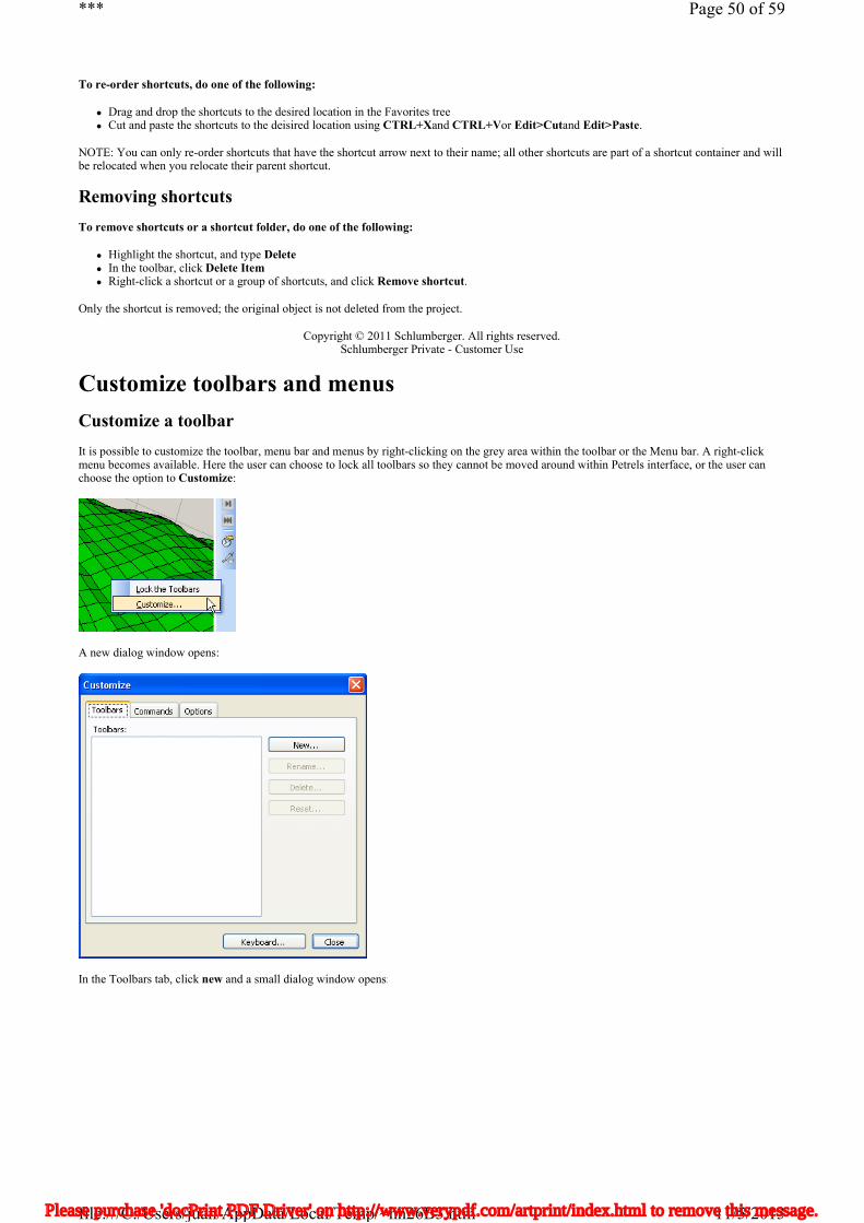
Understanding reservoir juxtapositions and fault properties is critical to accurate well placements and optimal production strategies. Fault seal analysis is also a critical step in prospect generation and field appraisal. The Petrel Structural and Fault Analysis module allows you to performfault seal analysis faster, more simply, and with greater accuracy and repeatability. This toolset was developed in collaboration with Rock Deformation Research, in Leeds, UK. The module also provides front-line fault juxtaposition and property mapping tools for exploration and production environments.
Page 5 of 59***
11/5/2013file:///C:/Users/juan/AppData/Local/Temp/~hh26B3.htmPlease purchase 'docPrint PDF Driver' on http://www.verypdf.com/artprint/index.html to remove this message.
� identification and mapping of critical high-flow zones or seal continuity areas � rapid understanding of the influence of faults and stratigraphic models � real-time creation and interaction with faults in the common seismic-to-simulation environment � dynamic fault property updating for faster and more accurate history-matching � integration of core data to allow calibration and reduce uncertainty � uncertainty analysis of fault sealing properties.
An extensive list of methods to model complex geological features and connectivity
Model your pixel- or object-based stochastic facies using deterministic techniques. Condition the facies to a seismic property or trend surfaces with the data analysis process, or use objects sampled directly from seismic with the volume extraction tool.
Benefits
� Use a 3D facies model to incorporate lithological information when modeling reservoir properties such as porosity. � Guide your algorithms with a range of trends.
Multipoint geostatistics
Traditional reservoir modeling techniques use simplified, two-point statistics to represent geological phenomena that have complex geometrical configurations. The use of multipoint statistics has improved in recent years, reducing previous limitations. The Petrel 2009 software release introduced a multipoint facies simulation (MPFS) algorithm, providing users with new methods to model complex geological features and connectivity. These workflows work efficiently in multimillion cell models and honor well, seismic, and probability data. The workflows are much faster than before and use less than 5 percent of the memory needed to run MPFS in the model, improving performance when using training images. Petrel 2010 introduces a new simplified training image and pattern creation process, which, combined with the new user-defined object creation process, allows the geologist to create realistic training images that are reproduced by the MPFS algorithm.
Object modeling
This stochastic method to distribute facies objects in the 3D model uses a variety of predefined geological shapes, including fluvial channels with levees. Petrel software also offers alternative adaptive channels, better suited for honoring a greater number of wells and ensuring connectivity.
Sequential indicator simulation
A stochastic, pixel-based method combines variograms and target volume fractions with the optional use of 1D, 2D, or 3D trend data to simulate a 3D facies model. It is most appropriate when either the shape of particular facies bodies is uncertain, or a number of trends control the facies type, for example, when using a seismic attribute to control the probability of the occurrence of certain facies.
Truncated Gaussian simulation
A very useful stochastic method for modeling environments where there is a natural transition through a sequence of facies. Typical examples include carbonate environments and progradational fluvial sequences. A modified version of the traditional TGSim function is implemented in Petrel software as the Truncated Gaussian simulation with trends, allowing for much better control of the borders between each facies type to be modeled.
Indicator kriging
Petrel Facies Modeling features indicator kriging, a deterministic, pixel-based method for producing facies models based on kriging probabilities.
Interactive editing
Use the intuitive drawing tools, such as pencil, brush, and airbrush, as a standard drawing package. Edit your facies models and use them as a background in any of the facies modeling methods, or simply deterministically define the presence of a type of lithology in your model.
Other features
Employ the Data Analysis and Trend Modeling processes to investigate and edit trends in the data, condition the model to a seismic cube, and build variograms
Page 6 of 59***
11/5/2013file:///C:/Users/juan/AppData/Local/Temp/~hh26B3.htmPlease purchase 'docPrint PDF Driver' on http://www.verypdf.com/artprint/index.html to remove this message.
� Use the scientific calculator for calculations. � Filter by index, zone, segment, value, and upscaled cells. � Generate synthetic logs for well trajectories.� Generate connected volumes. � Visualize facies in the mapping module for printing scaled maps and intersections in combination with any other filtered or unfiltered data.
Using a standard layer cake approach for domain conversion, Petrel gives you the freedom to select velocity variations for each model layer, while maintaining a time/depth consistency between all faults and horizons.
Benefits
� Provides both standard layer cake approach with interval velocities and use of average velocities down to each horizon � Handles depth conversion of normal and reverse faulting with the same ease � The 3D grid depth conversion process maintains and honors the relationship between the faults and horizons, ensuring a consistent model
both in time and depth. � Build models in time or depth. Models constructed in time to be easily converted to depth.
The depth conversion process converts the corner-point grid of the model on a node-by-node basis, including all the grid pillars and faults. The process allows you to analyze the uncertainty in the velocities by using different velocity setups. By reversing the process a time grid can be builtfrom a depth model.
Supported velocity methods
� Linear functions V=VO+kZ � Surfaces � Constant velocity
Petrel petrophysical modeling provides the following capabilities:
� Create 3D models of petrophysical properties using well logs. � Use 3D facies models and/or 3D seismic attributes to control and condition the model. � Apply a combination of modeling techniques for each run.
Deterministic modeling
The available deterministic modeling techniques include
� simple and ordinary kriging � moving average, based on inverse distance weighting� functional, based on function approximation � closest point.
Stochastic modeling
Petrel software uses sequential gaussian simulation for distribution of petrophysical property data in the 3D grid. This includes
� user-defined variogram and range� trends in vertical and horizontal directions � simple kriging, ordinary kriging, and colocated cokriging with secondary data; excellent for inversion data � conditional and unconditional simulation.
Random gaussian simulation
When the correlation between soft data and hard data is zero, the simulation depends on well data only and is completely independent of soft data, such as seismic. As the correlation increases, so does the dependence of the final result on the seismic data. Petrel software calculates the optimal correlation between seismic and porosity, and uses this as the default for colocated cosimulation. However, this correlation is one of the sensitivities that should be examined within an uncertainty study. The Petrel 2009 release gives users a quick visual appreciation of the correlation without having to restart the simulation every time.
Run your own algorithm
Page 7 of 59***
11/5/2013file:///C:/Users/juan/AppData/Local/Temp/~hh26B3.htmPlease purchase 'docPrint PDF Driver' on http://www.verypdf.com/artprint/index.html to remove this message.
Generate seismic attribute maps on any 2D surface or average seismic properties within a time or depth interval.
Benefits
� Display any seismic data with a 3D depth converted model. � Import a simulation model into Petrel and quality check it with the seismic data. � Condition your reservoir model with depth converted seismic attributes sampled into the grid.
Seismic depth conversion
With a simple click, your seismic volume is depth converted according to the velocity functions for the horizons in a 3D grid. When a seismic volume is depth converted, Petrel will locate the time horizons and the corresponding depth horizon in the two 3D grids and adjust the Z-position of each seismic trace. The resulting depth converted seismic will be restricted to the boundaries of the 3D depth grid.
The depth converted seismic allows the same options as original seismic, including 3D auto tracking and manual interpretation. You can display the volume in the interpretation window and create attributes from the depth data.
Quality control
� Display the depth converted seismic with property grids or results from simulation to ensure the quality of the modeling. � Different disciplines can work together on the same interface. � Sample depth converted seismic amplitudes or attributes into an existing 3D grid.
Sampling
Sampling is the process whereby Petrel investigates the attribute values within a grid cell and populates the grid cells with one attribute value. The algorithms that can be used in this process are: closest, interpolate, intersection, and exact.
To obtain a realistic and accurate model, the sampled seismic attributes can be used to guide or condition the property modeling.
Modeling flow in fractured reservoirs is a challenging task that requires a solution that unifies the static and dynamic reservoir modeling disciplines. Petrel software provides the optimal environment to visualize, analyze, and integrate the various data types that may be direct or indirect indicators of the presence of fractures, which will then be carried on as input parameters for their stochastic distribution.
Advanced technology for better workflows
In Petrel 2010, the fracture networks can be modeled by a smart combination of discrete and implicit fractures, a revolutionary method that eliminates the usual problems related to memory handling because of the high number of fracture planes generated by a typical discrete representation. Expanded from the original technology from Golder Associates - a leader in fracture modeling - the fracture property upscaling workflow generates the final fracture parameters necessary for the reservoir fluid-flow characterization
Benefits
� Comprehensive and easy-to-use tool to model fracture networks. � Works directly in Petrel software and uses all available tools (i.e., train estimation and model, process manager, property calculators,
modeling processes, etc.).� Integrated support with ECLIPSE triple-porosity models makes it even simpler to simulate naturally fractured reservoirs.
Handle Data Estimation and Forward Modeling Problems
Neural networks have emerged as proven technology to handle property estimation and forward modeling problems. The Classification andEstimation module provides an alternative to the current Petrel deterministic and stochastic 3D property estimation techniques, and introduces new
Page 8 of 59***
11/5/2013file:///C:/Users/juan/AppData/Local/Temp/~hh26B3.htmPlease purchase 'docPrint PDF Driver' on http://www.verypdf.com/artprint/index.html to remove this message.
workflows for log estimation, property mapping, and seismic facies classification. The module also introduces the new Trend Modeling process, which allows the estimation of 3D facies probability volumes based on upscaled well data and optional secondary variables such as seismic attributes.
Train estimation model process—how it works
This process gives you access to tools for neural network analysis, enabling you to train and then create the estimation model object. Input data types include
� well logs � surfaces with attributes, including seismic attribute maps � 2D or 3D seismic data � 3D properties, both discrete and continuous points with attributes.
Predictive modeling
Once nonlinear functions have been created, the estimation model can be used for predictive modeling on a wide variety of data types via the appropriate Petrel process:
� make well logs - well logs � multi-trace attribute generation - seismic attribute cubes � facies modeling - discrete property generation � petrophysical modeling - continuous property generation� make surface - surface attributes (including seismic attribute maps)
Trend modeling
A realistic facies model built from all available integrated data is an important step in a reservoir characterization workflow, so pay reservoirs, volumetric estimations, and cell connectivity are more accurately estimated. The Trend Modeling process allows you to combine facies log interpretation and 2D or 3D seismic attributes to create vertical proportion volumes that can be used later to drive the distribution of facies in the 3D model.
Advantages
The Train estimation model process and related predictive modeling methods bring a generalized neural network implementation for the estimation of well logs, surfaces, seismic volumes, and 3D property models. It is an alternative to geostatistics when a nonlinear relationship exists between a set of input data and a given output, or when there is no single variable or set of two variables that provides an adequate correlation.
With the Trend Modeling process, the geologist is able to reproduce realistic sedimentary environments, bridging the gap between 1D and 2Ddata, geological concepts, analogs, and 3D modeling world.
Design wells interactively by digitizing the path directly in the 3D window—on any type of data including raw seismic, property models, or simulation results. Edit well nodes in the 3D window or the spreadsheet editor, or copy and paste into Excel for editing.
Minimize the total cost of your drilling program
Automatically generate well trajectories and platform locations for a set of reservoir targets to minimize the total cost of your drilling program using the Petrel Well Cost Optimizer (part of the Well Path Design module). Targets defined as "must hit" data points for the optimized well pathscan be locked to platforms, and target-platform sets can be constrained by closed boundaries. Automatically computed well trajectories are constrained by a user-defined dogleg severity. The output is a set of optimized trajectories based on geometrical drilling constraints extending from the reservoir back to the surface. The Drilling Difficulty Index (DDI) provides a first-pass evaluation of the relative difficulty encountered in drilling a well.
Benefits
� Automatically generate well trajectories and platform locations that minimize the total drilling program cost. � Manually design wells quickly in 3D, directly on seismic lines, property models, STOIIP maps, and even simulation results. � Display well path segments that exceed your specified dogleg severity. � Create instant well reports and synthetic property logs. � Export generated well paths for use in drilling and reservoir simulation packages.
Petrel Workflow Editor and Uncertainty and Optimization Process
Page 9 of 59***
11/5/2013file:///C:/Users/juan/AppData/Local/Temp/~hh26B3.htmPlease purchase 'docPrint PDF Driver' on http://www.verypdf.com/artprint/index.html to remove this message.
The Workflow Editor, an integral part of Petrel software, captures data parameters and relationships that enable rapid updating of reservoir models as information from new wells arrives. The Workflow Editor allows the user to create all sorts of workflows to be run in batch mode, whether to run repetitive tasks, or to recreate an object or an entire grid.
Geoscientists and engineers can create multiple model realizations to assess the impact on reserve volumetrics or to cost well placement. Withoutleaving Petrel, engineers can run all possible scenarios in ECLIPSE software directly.
The Workflow Editor improves uncertainty understanding and risk management, and allows best practices and workflows to be easily shared across your organization.
Petrel software enables asset teams to reduce project cycle time and maximize productivity.
Open API for external algorithms
Petrel software provides the ability to plug in external algorithms for uncertainty analysis in the Workflow Editor. Users can now apply their own experimental design algorithms or optimizers using the Ocean application development framework on top of the new proxy models introduced in Petrel 2010.1.
With the Surface Imaging utility you can drape a surface with any image, including aerial or satellite images, scanned maps, seismic time slices, or property maps. For example, in a hilly terrain, you can drape a satellite image over the model to check access to proposed drilling sites. You can also drape maps or property surfaces over models.
Build 3D models when only paper data is available. Paper maps can be scanned and then imported as images, from which digital maps can be created by digitizing the contours.
Benefits
� Drape satellite images over the topographic surface to precisely locate surface features. � Import scanned maps or drawings, oriented correctly in 3D space and draped over a surface. � Drape property maps, isochore maps, and maps of any seismic attribute over time or depth surfaces.
Workflow
� Import images in a range of formats and drape (project) over surfaces in the Petrel model. � Set corner coordinates. � Grid images where the pixel intensity is used as elevation. This is an excellent way to display images together with your Petrel models.
Petrel geophysics software provides a full spectrum of geophysical workflows, including 2D and 3D interpretation, a full set of complex volume and surface attributes including ant tracking for the identification of faults and fractures, volume interpretation (geobody detection) with seismiccrossplotting and classification, domain conversion, and the modeling-while-interpreting functionality, which enables interpreters to build astructural framework while doing their interpretation.
Petrel geophysics is a fully scalable solution that supports seismic data from different coordinate systems, taking you seamlessly from regional exploration to reservoir development.
Petrel exploration geophysics
� Unprecedented access to extremely large seismic datasets—work with hundreds of gigabytes of 3D seismic volumes and thousands of 2D lines, all in a 3D canvas
� Scalable interpretation at your desktop—to visualize and interpret data � Modeling-while-interpreting capability—to produce higher-quality interpretation by building a structural framework in the background
while you interpret � Improved volume interpretation—to identify and extract geological features by blending and sculpting volumes� Uncertainty and volumetrics assessments—to evaluate potential risk in a single application
Petrel Seismic Interpretation
Petrel Seismic Interpretation
Page 10 of 59***
11/5/2013file:///C:/Users/juan/AppData/Local/Temp/~hh26B3.htmPlease purchase 'docPrint PDF Driver' on http://www.verypdf.com/artprint/index.html to remove this message.
Visualize and interpret regional 2D and 3D seismic data manually or use advanced auto-tracking techniques. Interactively create attribute maps of horizons or intervals.
Interactively blend multiple seismic volumes, isolate areas of interest, and then instantly extract what is visualized into a 3D object called a geobody.
Petrel Seismic Attribute Analysis
Petrel Seismic Attribute Analysis
Generate and analyze seismic attributes to enhance information that might be subtle in traditional seismic, leading to a better interpretation of the data.
Petrel Domain Conversion
Petrel Domain Conversion
Quickly perform domain conversion backwards and forwards between time and depth. Create your velocity models directly in Petrel or import from any third party application.
Petrel Seismic Sampling
Petrel Seismic Sampling
Convert your seismic data to depth and resample the seismic attribute into the 3D structural grid as a property.
Petrel Synthetic Seismograms
Petrel Synthetic Seismograms
Bridge the gap between your time and depth domains.
Petrel Automated Structural Interpretation
Petrel Automated Structural Interpretation
By focusing on structural geology rather than conventional segment picking, Automated Structural Interpretation reduces conventional interpretation time while increasing your level of geological detail, structural awareness and reservoir understanding.
Petrel Automated Structural Interpretation - Ant Tracking
Classification and Estimation
Classification and Estimation
Estimate well logs, surfaces, seismic volumes, and 3D property models using neutral network technology.
Petrel Well Path Design
Petrel Well Path Design
Design well paths, identify surface locations, pick targets, and adjust trajectories dynamically in a 3D canvas to find the optimal solution.
Combine 2D and 3D Seismic Interpretations in a Unified Environment
Petrel seismic interpretation software seamlessly combines the workflows of 2D interpretation with the visual and performance benefits of 3D volume interpretation. You can leverage an interpretation environment unified with geology, reservoir modeling, and reservoir engineering domains and have the ability to rapidly interpret seismic data and compare the results with other data in your project. Effortlessly move from interpretation to structural model building to property modeling and back, eliminating the gaps and inevitable knowledge and data loss of
Page 11 of 59***
11/5/2013file:///C:/Users/juan/AppData/Local/Temp/~hh26B3.htmPlease purchase 'docPrint PDF Driver' on http://www.verypdf.com/artprint/index.html to remove this message.
traditional systems that require handoffs from one technical domain to the next.
2D seismic interpretation
Unlock more information from 2D seismic data by applying techniques that are typically reserved for 3D interpretation, including opacity control in the 3D canvas.
3D seismic interpretation
Visualize and interpret massive amounts of 3D data without loading all the data to RAM. Combine the traditional line-by-line approach with the latest algorithms and tools, including amplitude- and waveform-based tracking, for 3D volume interpretation. Rapidly identify stratigraphic or structural features, and then interpret horizon and fault though the volumes.
2D/3D multi-volume interpretation
Interpret across multiple 3D and 2D surveys—either in the interpretation or in 3D windows—to gain the best understanding in the shortest time. Interpret the same event across multiple surveys, and grid, contour, and map whole or partial events for individual surveys.
Modeling-while-interpreting (MWI) functionality
Pick faults in the background while Petrel software grids faults and applies fault connection rules, producing an accurate fault framework for your complex structure. Grid horizon interpretation to create a true water-tight model that can be used in the model or high-quality structural maps. And shorten the time it takes to create a complex model by providing a cleaner interpretation and creating the structural framework in advance.
Data management
Use the Seismic Survey Manager to effectively manage 2D and 3D seismic data within your Petrel project, improving your user experience when working with large regional areas, thousands of 2D lines with tens of thousands of traces, hundreds of kilometers and coordinate systems, and multiple 3D vintages and surveys.
Improve Reservoir Understanding, Detect Anomalies, and Define Facies
Visualize and extract 3D objects from seismic to improve reservoir understanding, detect anomalies, and define facies. Petrel software enables youto interactively blend multiple seismic volumes, isolate areas of interest, and then instantly extract what is visualized into a 3D object called a geobody. As the geobody is extracted, the interpreter can assign a geological template to the geobody, providing the body with instant geological meaning. Geobodies can be included directly in the 3D geological model, bridging the gap between geophysics and geology.
Geobody extraction
� Visualize the 3D object, isolate the body, and then interactively extract it. � Calculate volumetrics or sample the geobody directly into a geological model. � Use properties in much the same way as a facies model to condition petrophysical property models. � Filter by properties to perform data analysis, property modeling, and volume calculations on the grid cells within the bodies.� Blend multiple cubes together using seismic crossplotting and classification, and create complex selection events to identify stratigraphic
features. The classifications enable you to manually classify a set of attributes based on their relationships. � Use the automatic extraction algorithm to rapidly extract the bodies in the scene, then filter, merge, and delete these bodies. Once the
geobodies have been extracted, you can assign each a geological template easily sample them into the model.
Seismic volume rendering
Interactively apply transparency to regional 3D seismic volumes to rapidly identify areas of interest. You have the ability to set free volumes independent of inline x-lines and time slices.
Enhance Traditional Seismic Information for Improved Data Interpretation
The attribute generation process contains a library of different single and multitrace seismic attributes for display and use within the seismic interpretation workflow. Seismic attribute analysis helps to enhance information that might be subtle in traditional seismic, leading to a betterinterpretation of the data.
Genetic inversion
Page 12 of 59***
11/5/2013file:///C:/Users/juan/AppData/Local/Temp/~hh26B3.htmPlease purchase 'docPrint PDF Driver' on http://www.verypdf.com/artprint/index.html to remove this message.
Seismic reflection data is the primary input for resolving structural and stratigraphic variations between points of well control. Petrel software provides a fully integrated genetic inversion algorithm that enables geophysicists and geologists to more accurately predict interwell properties from seismic data in Petrel software. Horizon autotracking options allow you to pick directly on the impedance volume, or they can be used as an input in the enhanced geobody isolation and extraction process for improved reservoir characterization.
Surface attribute library for rapid prospect identification
The attribute library gives the user access to more than 40 attributes that can be instantly calculated directly at interpreted events, on nearby uninterpreted events, or between events. This enables the interpreter to extract maximum value from seismic data by providing more detail on thesubtle lithological variations of the reservoir.
Fault and fracture identification
Petrel software offers a full range of attributes to identify faults and fractures, including variance and dip-guided variance, ant tracking, and 13 different curvature attributes.
Enhancing seismic workflows
A variety of new workflows can be derived using attributes to
� precondition the data for better horizon autotracking � enhance the fault signature of the data by calculating variance or chaos, or by filtering structural smoothing with the edge enhancement
option � precondition the data for seismic facies extraction using relative acoustic impedance or the chaos attribute to isolate salt bodies � combine attributes and generate users' own attributes using the seismic calculator.
Geophysicists typically work in the time domain while geologists work with depth data. Petrel Domain Conversion reconciles these differences by helping you make depth data the rule rather than the exception.
Petrel allows you to quickly perform domain conversion backwards and forwards between time and depth. All the necessary steps are performed directly in your project, so there is no need to ever leave the friendly Petrel interface.
Petrel Domain Conversion involves two simple steps. First you create a velocity model and calibrate it to the available well markers. Next select the data you wish to domain convert, whether it is surfaces, horizon and fault interpretations, points, well data, 2D and 3D seismic, or 3D grids.
Benefits
� Domain conversion runs directly in Petrel, saving you time by avoiding unnecessary input and output of information. � Perform domain conversion at any stage in your workflow. Build 3D models in either time or depth, and convert when it is convenient for
you. � Build multiple velocity models to test different velocity parameter scenarios and obtain a better understanding of structural uncertainty. � Use a 3D grid property for depth conversion, useful for conversion of complex structures such as reversely faulted environments
Features
� Domain conversion of 2D and 3D seismic, surfaces, horizon and fault interpretations, points, wells and logs, well tops, and 3D grids. � Uses a standard layer cake approach for domain conversion, giving you the freedom to select velocity variations for each layer, while
preserving the relationships between faults and horizons.� Velocity modeling and depth conversion can be run in the Petrel Process Manager, allowing you to generate a single workflow that spans
both time and depth domains. � Supported velocity methods include linear functions V=Vo, V=Vo+kZ, V=Vo+k(Z-Zo). Constants or surfaces can be used as variables. � Can utilize externally generated velocity cubes to create velocity models.� Supports conversion within the same domain (Time to Time and Depth to Depth), enabling AVO and 4D seismic workflows and the
calibration of PreStack Depth Migration to well markers.
Bridge the gap between your time and depth domains.
Multi-trace synthetic generation lets you fine-tune your seismogram to match the seismic extracted in wells. The well correlation window helps you to assess the match. Any changes to the time-depth relationship can be made and seismic horizons can be correlated with the stratigraphic boundaries identified in your wells. When the time-depth relationship has been fine tuned, all depth indexed well tops will be automatically assigned the updated time value.
Benefits
Page 13 of 59***
11/5/2013file:///C:/Users/juan/AppData/Local/Temp/~hh26B3.htmPlease purchase 'docPrint PDF Driver' on http://www.verypdf.com/artprint/index.html to remove this message.
� Minimize data load and transfer by using one application where synthetics are integrated with seismic and well logs. � Improve your quality control by viewing your synthetic seismogram in a variety of windows including the 3D, interpretation or well
correlation windows. � Quickly process synthetics using the intuitive Windows guiding and help systems built into Petrel. � The easy-to-use copy/paste functionality allows you to quickly present your interpretations to management in any Windows application like
Word or PowerPoint.
Features
� Display synthetic seismograms with any other item in Petrel � Display wells in time � A "Process diagram dialog" guides you though the steps � Wavelet extraction from seismic � Well seismic
Display
The synthetic seismogram can be displayed in the well correlation window, 3D window and interpretation window.
Wells in time
When a time-depth relationship in wells has been established, wells can be displayed in the time domain in all 3D and intersection windows.
Process diagram dialog
The Synthetics process dialog leads you through the steps of generating synthetic seismograms from your well data, and simplifies the display of the data you need to use along the way.
Wavelet extraction from seismic:
Use a collection of traces around the borehole, compute auto-correlation for time window of interest, taper effects etc.
The workflow process for wavelet extraction involves trying several combinations of extraction parameters, recording the results, and trying different boreholes in order to gain a better understanding of the nature of the seismic data. The Wavelet Extract option in Petrel gives you the capability of extracting statistical wavelets from the seismic data at a borehole.
A wavelet can be extracted from some portion of a 3D volume of seismic traces. The statistical extraction method used in Synthetics assumes that the autocorrelation of the wavelet is the same as the truncated autocorrelation of the seismic trace. The average autocorrelation from severalseismic traces is used to provide a more representative estimate of the wavelet.
Well seismic
The seismic can be extracted along the well paths and displayed. The extraction is not limited to the synthetic seismogram generation, but can be done for any type of seismic volume; hence you can display your seismic attributes in with well logs in the well correlation window.
To access the synthetic seismograms you need the core module, well correlation and seismic interpretation module.
Increase accuracy while reducing your manual fault interpretation task
Understanding the trends of fault surfaces and fluid flow properties across fault systems is one of the most important aspects when it comes to reservoir characterization. For many years it has been possible to spatially interpret horizon reflections but interpretation of fault surfaces or planes has been more subjective.
The Petrel Automated Structural Interpretation module uses an advanced computing algorithm "Ant Tracking" to overcome this subjectivity. Now interpreters using 3D seismic data can spend time understanding the trends of fault surfaces and make correlations from the automatically extracted fault patches instead of creating fault surfaces individually and manually.
By focusing on structural geology rather than conventional segment picking, Automated Structural Interpretation reduces conventional interpretation time while increasing your level of geological detail, structural awareness and reservoir understanding.
Benefits
� Increases structural accuracy and detail � Significantly reduces tedious manual interpretation time � Provides unbiased, repeatable and highly detailed mapping of discontinuities � Fully integrates with geological modeling � Better estimation of complex models � Optimizes the value of 3D seismic data beyond traditional picking
Page 14 of 59***
11/5/2013file:///C:/Users/juan/AppData/Local/Temp/~hh26B3.htmPlease purchase 'docPrint PDF Driver' on http://www.verypdf.com/artprint/index.html to remove this message.
Petrel Automated Structural Interpretation - Ant Tracking
Looking at faults and fault systems that may be the result of tectonic forces from completely different directions which have affect on ultimate hydrocarbon recovery.
Preprocessing and Postprocessing of Simulation Data
The Reservoir Engineering component of Petrel seismic-to-simulation software enables experts to meld the richness of their domain-specificinformation and knowledge into a single model-centric subsurface representation, while also delivering a comprehensive reservoir simulation preprocessing and postprocessing environment.
Now, changes in the seismic interpretation or the geological model easily cascade through to the reservoir simulation model and back. You can evaluate the impact of the changes on production rates or reserves—in a fraction of the time previously achievable. Compatible with the entire family of ECLIPSE reservoir simulation software and other industry simulators, the Petrel Reservoir Engineering (RE) workflows enable dynamicanalysis to meet your business or operational needs.
Complex wells
Petrel RE enables you to design sophisticated wells with multisegmented design, advanced completion design, automated placement, and completion optimization.
Simulation gridding
Petrel 2010 gridding capabilities include logarithmic local grids around hydraulic fractures in wells, local coarsened grids, tartan grids to reduce the number of cells, gridding of complex geological structures, and stair-step gridding to honor Y faults.
Thermal simulation
Petrel RE software supports live oil thermal fluids workflows that enable you to set up, run, and analyze data where thermal recovery processes are occurring.
Development strategies
The development-strategy process includes a set of rules for controlling reservoirs and wells that enable you to exercise more of ECLIPSE software’s functionality within Petrel software.
Aquifer modeling
Petrel 2010 provides tools for aquifer modeling—for precision and robustness in handling aquifer connections.
Integrated workflows
Petrel software integrates workflows around simulation, makes the data flows transparent, and makes the interface easy to learn.
Petrel Advanced Gridding and Upscaling
Petrel Advanced Gridding and Upscaling
Resample and re-grid fine-scale geological models to coarser-scale simulation models using a wide range of upscaling techniques.
FrontSim
FrontSim
Use this three-phase, 3D simulator to model multiphase flow of fluids along streamlines.
Petrel History Match Analysis
Petrel History Match Analysis
Analyse history matching studies by computing and visualizing statistics, comparing simulated with actual history.
Petrel Reservoir Engineering Core
Petrel Reservoir Engineering Core
Page 15 of 59***
11/5/2013file:///C:/Users/juan/AppData/Local/Temp/~hh26B3.htmPlease purchase 'docPrint PDF Driver' on http://www.verypdf.com/artprint/index.html to remove this message.
Use a wide range of gridding and upscaling techniques
Resample fine-scaled geological models to coarser-scale simulation while still preserving important details in the geologic model. An assortment of averaging methods includes a flexible tensor upscaling function for determining effective permeability in each simulation cell.
Advanced gridding techniques include:
� Local gridding (LGR) — to create small cells around wells, surface, or polygons for improved resolution
Stair step (IJK) gridding — to ensure grid orthogonality when faults are highly inclined
Advantages
� Preserve geologic knowledge scale—construct a simulation grid from the same 3D model as your fine-scale geological grid � Get an accurate upscaled representation of your modeled properties—from standard averaging or flow-based tensor techniques� Capture complex structural or near-wellbore effects—using advanced gridding techniques
Flow-based tensor upscaling-how it works
When upscaling permeability from a fine geological grid to a coarser simulation grid, a block of grid cells from the fine grid will have direction-dependant permeability. This is modeled using a permeability tensor.
The default output is permeability properties for X, Y, and Z. You can also request coupling terms XY, XZ, and YZ. In situations where there are only a few cells in each coarser cell, you can define a skin zone that includes additional cells outside the coarse cell to calculate the upscaled permeability. The larger zone improves the pressure field calculations and the accuracy of the flow relative to directional permeability differences
Rank and screen reservoir models in a dynamic environment by combining industry-standard streamline technology with intuitive and interactive 3D modeling. FrontSim streamline reservoir simulation software is a three-phase, 3D simulator that models multiphase flow of fluids alongstreamlines. The FrontSim simulator enables you to construct enhanced reservoir models quickly, paving the way for more accurate production forecasting and better decisions.
Benefits
� Efficiently rank, screen and visualize multiple sensitivity runs, combining static and dynamic information to create more reliable models in less time.
� Optimize well placements by combining streamline analysis with the detailed static model to enhance sweep efficiency. � Validate upscaled reservoir models with dynamic data by understanding grid orientation issues, thereby improving the quality of the model
used for reservoir simulation.
Identify flow patterns
When heterogeneity and reservoir uncertainties are dominating the fluid flow behavior in your reservoir, stochastic modeling techniques are used
Page 16 of 59***
11/5/2013file:///C:/Users/juan/AppData/Local/Temp/~hh26B3.htmPlease purchase 'docPrint PDF Driver' on http://www.verypdf.com/artprint/index.html to remove this message.
to create multiple views of your fine scale geological model.
With FrontSim software, you can dynamically identify the tortuous flow paths by visually depicting the injector-to-producer streamline bundles and make ranking decisions based on production history, not static methods alone.
Improve your reservoir management
Identifying optimal drilling locations is not only based on engineering constraints, but also on reservoir heterogeneity. Running the FrontSim simulator on your fine scale geological model lets you identify injectors not contributing to production, or producers that are cycling injected water. Such analysis lets you make development and field management decisions to optimize sweep, improve ultimate recovery and minimize injection costs.
Build better quality models
Identifying the representative model from stochastic analysis is challenging enough. Fine scale geological models must then be upscaled to reduce the number of cells for practical full-field simulation.
The knowledge gained using the FrontSim module can directly impact ECLIPSE reservoir simulation models, resulting in more reliable models with better predictive forecasting.
Simplify the history matching process and arrive at best history match sooner. The efficient, easy-to-use Petrel History Match Analysis module lets you quickly and easily analyze hundreds of ECLIPSE reservoir simulation runs to isolate the most likely geological realization.
Advantages
� Quantify history match quality to identify the best-possible realization � Identify history match problems in the field from immediate graphical results � Manage hundreds of runs and cases with simple case management tools � Change properties and rerun all cases from any ECLIPSE family of simulators thanks to complete integration with Petrel
History match analysis - How it works
The tool calculates statistics on the quality of a history match across many realizations and highlights the best matches for further study. Results are calculated on every well and for every data type (oil rate, water rate, bhp, water cut, etc.)
By combining different matches into scenarios, you can move from a case view to a field view and down to the specific details in any well. Theresults are then displayed in a map window with color codes indicating good and bad history matches. Instead of looking at hundreds of line plots and trying to find the best case, the cases are ranked according to your choices.
Your entry point for detailed ECLIPSE simulation and pre- & post-processing
The Petrel Reservoir Engineering Core lets you select and launch the appropriate ECLIPSE simulator and analyze your results—all within Petrel.
Build efficient simulation models. Use this tool to build ECLIPSE simulation models directly from your geological models, adding fluidproperties, well completions, production history, and event scheduling. Organize geological realizations and develop scenarios into cases.
Advantages
� Integration and improved communication between Geophysics to Reservoir Engineering � Access to the Petrel process manager allows for rapid model updates and simulation based uncertainty quantification � Petrel usability for the petroleum engineers
Features
� Well completion design - import tubing and completion data; interactively create completion string specifications alongside the log view of the well; intersect the completion description with the grid and calculate connections to grid cells for the simulator; specify completions relative to horizons and copy them from well to well
� Flow controls - import historical production rates and average them up into simulation control time steps; set prediction controls and economic limits
� Fluids - import or create from correlations the pressure, volume, temperature (PVT) properties for oil, water and gas � Case definition - select which realization of each grid, property, and engineering data is to be used in a simulation run; copy cases, make
modifications; and run them directly in ECLIPSE � Results and case trees - manage cases in folders and analyze the results in the new results tree
Page 17 of 59***
11/5/2013file:///C:/Users/juan/AppData/Local/Temp/~hh26B3.htmPlease purchase 'docPrint PDF Driver' on http://www.verypdf.com/artprint/index.html to remove this message.
The Studio E&P knowledge environment inspires creativity in three key dimensions: personalization, collaboration, and access to critical insights, information, and results. Studio improves Petrel users’ productivity with enhanced data access and point-to-point session sharing.
My Petrel - Personalization
Favorites — Personalize across all domains to focus on current data, projects, and mini-scenarios
� Minimize time spent tree surfing � Store shortcuts to data, processes, windows, and workflows � Increase productivity with relevant data processes, models, results, and templates in a user-configured list—all of which act as they do in the
Petrel tree
Collaborate
Find — Smart search, access, and scalability across your Petrel data world
� Google-style text search across your Petrel data domain, enhanced by smart filters� Search from within your familiar Petrel 2D and 3D windows to see all your data in context. Zoom in for more detail � Enhance Petrel with access to Web map services. Easily adjust layers for transparency and depth � Right click to load from search into the project, with automatic coordinate transformation
Annotate — Enrich Petrel projects with knowledge in context
� Attach georeferenced notes, images, links, and documents � Promote discussion on key asset decisions � Enhanced project history and tracking
Share — Enhance performance and collaboration with session sharing
� Easy point-to-point Petrel sharing � Integrate with Annotate to capture knowledge-sharing� Remote session display and control � Specific Petrel configuration, accelerated Web meeting screen-sharing � Simple Petrel plug-in deployment—www.ocean.slb.com
Knowledge
Transfer — Access, publish, store, and enrich your company’s knowledge base
� Petrel identity history, templates, and folders � Publish model provides data matching, filters, and repository managers � Click to sync latest data, in real time� Context and quality tags, new quality attributes for data items� Scalability and performance to streamline data workflows
Well path design, drilling visualization, and real-time model updates
Petrel workflows improve operational efficiency by setting an environment to visualize and understand relationships between the drillingprocesses in the earth context.
Benefits
� Maximize reservoir exposure by designing a well trajectory, understanding at initial stages the potential risks the well might be exposed to � Understand the relationship between actual undesired drilling events (well control, mud losses, wellbore stability, stuck pipe, etc.) in
geological context � Monitor execution in a proactive manner in real time to ensure optimum well position and foresee potential risks when the actual well path
trajectory is approaching a risk zone, deviations from planned well trajectory, and variations in the prognosis.
Drilling Visualization for Petrel
Drilling Visualization for Petrel
Visualize undesired drilling events in geological context to enhance both the well design and the execution of drilling operations through a
Page 18 of 59***
11/5/2013file:///C:/Users/juan/AppData/Local/Temp/~hh26B3.htmPlease purchase 'docPrint PDF Driver' on http://www.verypdf.com/artprint/index.html to remove this message.
Drilling events such as lessons learned, best practices, and risks encountered on offset wells (such as kicks, losses, high/low pressure zones, and other difficult drilling conditions) can be easily imported into the Petrel application. Geologists can improve well proposals by visualizing and correlating the events on the 3D and well section windows. Better collaboration while drilling produces more feasible well proposals.
Drillers proactively reduce risk
Risks and events can also be entered directly and edited as needed. They can be migrated to a planned well, reclassified and correlated to geology. Importing the Osprey Risk drilling risk prediction model allows a comprehensive view of simulated drilling risks alongside the event-driven drilling knowledge.
The entire operations team makes better decisions
Visualizing these risks and events in the overburden shared earth model enables the entire team to monitor the impact of geology interpretation changes on the drilling process, minimizing geologically driven risk.
Real-time risk is effectively managed
Risks can also be exported in WITSML format for proactive use in other tools, used in Real-time Drilling, such as PERFORM Toolkit real-time and postdrilling data optimization and analysis software and PERFORMView real-time drilling monitoring and visualization software.
Benefits
� Enhance well planning with knowledge correlation and create better well proposals. � Collaborate while drilling. � Reduce risk by dynamically updating a common earth model with real-time drilling data.
The Petrel Real-Time Data Link can connect to streaming real-time data from InterACT wellsite monitoring and data delivery system. This gives you a secure, real-time data link directly from the wellsite to the desktop.
The Petrel Real-Time Data Link can also connect WITSML data sources, from any vendor, to wells in Petrel, allowing you to load trajectory and log data. This data is saved with your Petrel project for later use.
Now, the Petrel shared earth model can be driven by real-time data, allowing you to understand the full impact of new geologic knowledge on the well while it is being drilled. Surveillance in a shared earth model while drilling allows effective cross-discipline collaboration in real time.
11/5/2013file:///C:/Users/juan/AppData/Local/Temp/~hh26B3.htmPlease purchase 'docPrint PDF Driver' on http://www.verypdf.com/artprint/index.html to remove this message.
Petrel is a PC-based workflow application for subsurface interpretation and modeling. It allows users to perform various workflows, from seismic interpretation to reservoir simulation. Geophysicists, geologists and reservoir engineers can move across domains, rather than applications, through the Petrel integrated toolkit.
Key benefits
All tools from seismic interpretation to simulation are integrated in one application, eliminating import and export problems and promoting collaboration.
Strong visualization capabilities give you instant QC of all data in 3D.
Models can be updated instantly when new data arrives, allowing the user to make quick and reliable decisions.
Most results can be copied and pasted to any Windows application, making it quick and easy to report and present your latest results.
Petrel has a familiar Windows user interface, undo/redo functionality, and stores modeling history, making it easy to use and learn.
The wide range of functionality in Petrel covers:
� 3D visualization � Well correlation � Classification and Estimation (Artificial Neural Net) � Creation of synthetic seismograms � Seismic attributes � Geobody Interpretation � 2D & 3D seismic interpretation and modeling � Seismic volume rendering and extraction � 3D mapping � 3D grid modeling for geology and reservoir simulation � Velocity Modeling (Domain Conversion) � Well log upscaling � Facies Modeling� Petrophysical Modeling � Data Analysis � Uncertainty Analysis� Optimization � Workflow editor � Fracture Modeling � Volume Calculation � 3D well design � Streamline simulation � ECLIPSE Simulation � Simulation post-processing � Remote Simulation Run submission� Plotting
To contact Petrel see Support.
Online Help
This document describes the use of the Petrel software and helps new users to get started and advanced users to improve their existing skills.
Hard Copy
To get a hardcopy of the Online Help manual, please go to the Contents tab and use the print function. You may print the selected topic only or all the topics in the selected heading.
Petrel
The use of Petrel is controlled through a license and may be used only in accordance with a license agreement.
Petrel is a registered trademark.
Third party
Tornado plots are generated using third party software Chart FX which is a registered trademark for Software FX, Inc.
11/5/2013file:///C:/Users/juan/AppData/Local/Temp/~hh26B3.htmPlease purchase 'docPrint PDF Driver' on http://www.verypdf.com/artprint/index.html to remove this message.
Information on how to use Petrel may be found in the following resources:
� Release notes and 'What's New in Petrel'. Read these documents for a detailed description of updates and new features coming with the new release.
� The Online Help System . Consists of two parts: This Online Manual and Hypertexts (Tips buttons) that shows a short description of items selected by the cursor.
� Training: For specialized or in-depth information about Petrel, contact your nearest Schlumberger office to sign up for an advanced training course. Schlumberger also arranges training courses upon client request.
� To get access to the complete worldwide classroom training offering and registration for Petrel, please see http://www.slb.com/services/software/training/standard_courses.aspx
� Classroom course offerings for Petrel are the following:� Petrel Introduction � Petrel Data Management � Petrel Seismic Visualization and Interpretation � Petrel Play to Prospect Identification� Petrel Structural Modeling � Petrel Property Modeling � Petrel Advanced Property modeling � Petrel Mapping and Geological workflows� Petrel Applied Well Correlation � Petrel Fracture Modeling � Petrel Workflow Editor and Uncertainty Analysis � Petrel Velocity Modeling� Petrel for Reservoir Engineers � Petrel RE Advanced topics � Petrel Upscaling and Simulation Gridding
� e-Learning courses area also available at http://www.slb.com/content/services/software/training/elearning.asp:
� Support With a manintenance agreement you will recieve support from your nearest Schlumberger SIS support site.� Support portal: A complete Login service https://support.slb.com/default.aspx delivering online resources such as a knowledge base,
support request submissions, discussion forums, software news etc.� Consultant Services: For help on specific projects, contact your nearest Schlumberger SIS office for a quote on consultant services. Also
have a look at our general site offering on the web http://www.slb.com//content/services/software/services/consulting_services.asp?
Getting Help in Petrel
Additional help in Petrel is provided via the:
Page 21 of 59***
11/5/2013file:///C:/Users/juan/AppData/Local/Temp/~hh26B3.htmPlease purchase 'docPrint PDF Driver' on http://www.verypdf.com/artprint/index.html to remove this message.
� Button tips - Short description of objects in the user interface. The description appears when the cursor is placed on an object. � Status bar - Information on selected objects and processes found at the bottom of the user interface. � Tool tips - Help located within dialog boxes. Hold the mouse over the button to see the text.
Contact Petrel support via your local Schlumberger office. For more information on Training and Support, see Help System Information
Support portal: Login to the http://support.slb.com/New_home/New_Petrel/tabid/156/Default.aspx for access to Petrel resources such as a knowledge base, support request submissions, discussion forums, software news, software downloads etc.
Information required for Prompt Support
In order to be able to address your request in the most efficient manner, we ask that you provide the following information whenever you contact your local Schlumberger support center:
Petrel Installation Issues & Application Errors
� Computer Manufacturer & Model � Processor (CPU) Manufacturer, Model & Speed � Computer Memory (RAM) � Graphics Card Manufacturer, Model, Driver Versions and Onboard Memory (DDR RAM)� Operating System and Version � Petrel Version and Build Date � Other applications running Simultaneously with Petrel � Detailed description of the problem � Embedded image(s) of application errors (if present)
Petrel is a Windows based software for 3D visualization, 3D mapping and 3D reservoir modeling and Simulation. The user interface is based on the Microsoft Windows standards on buttons, dialogs and help systems. This makes Petrel familiar to the majority of geoscientists today and ensures efficient usage of the application.
Petrel is a system for
� Seismic visualization and interpretation by using SEG-Y and ZGY data cubes in 2D and 3D windows. � A seismic Calculator can be used for advanced operations on several cubes. � Automatic Fault Extraction with the Ant tracker attribute. � Seismic Volume Rendering, which allows the seismic volume to be more or less transparent. � The new Petrel Geobody interpretation module employs state-of-the-art volumeblending technology to quickly isolate, extract, and integrate
a body directly into a property model for true 3D volume interpretation.
� Building faulted 3D grids for reservoir modeling and flow simulation. A new approach for building faulted 3D grids is introduced which makes the grid generation process significantly faster while producing high quality results. There are few restrictions to the complexity of the fault pattern or fault types in Petrel.
� Gridding of 2D structural surfaces honoring inter-surface relationships (erosion, onlap, etc.) and the generated 3D fault model. This method of gridding structural surfaces (3D mapping) is a true 3D approach and is unique to Petrel.
Page 22 of 59***
11/5/2013file:///C:/Users/juan/AppData/Local/Temp/~hh26B3.htmPlease purchase 'docPrint PDF Driver' on http://www.verypdf.com/artprint/index.html to remove this message.
� 3D visualization of geophysical, geological, petrophysical and production data. Petrel has an option to use 3D glasses for obtaining a true 3D effect (Virtual Reality).
� Flattening of the 3D grid using a horizon as datum. � The 3D grid can be depth converted node by node by using different velocity models.� Making an improved zonation of the reservoir by using the Well Correlation facility. � Analysis of well data, upscaled wells and properties, including data transformations and a comprehensive variogram analysis package. � 3D property modeling based on well logs and trend data (stochastic, deterministic). This includes a calculator for solving complex
mathematical equations involving one or several 3D property models; i.e. Sw transforms based on porosity and permeability 3D models. � Facies Modeling using stochastic and deterministic methods. � Fracture network modeling using for creating fracture properties as direct input to dual Porosity/Dual Permeability simulation. � Volume calculations, data analysis and plotting.� Upscaling of geometric grids and properties. � Streamline simulation using FrontSim. � Run ECLIPSE from Petrel. Set up an ECLIPSE Run in Petrel using Petrel grid and properties. E100 can be used for Black Oil simulation,
and E300 for Compositional Simulation. There is also a library of more advanced Keywords which can be used in addition to the standard setup in Petrel.
� Post-processing of simulation result data. � History Matching.� Well design in 3D. Digitizing, editing and visualizing of well trajectories based on the generated geological models. Output spread sheets
with detailed well report and synthetic well logs. � Well Optimizer to create a series of cost-dependant realizations based on Target points and cost model. � Improved documentation and reporting of the project work through tight integration with desktop tools like PowerPoint, Word and Excel.
Petrel is a software package that allows the user to build a reservoir model all the way from Seismic cubes to upscaled grids with properties, ready for export to a simulator or for being simulated in Petrel.
The Processes pane, shown in the lower left corner of the user interface, gives the user an overview of the suggested workflow in Petrel. Export and plotting are not a part of the workflow since that can be done at any stage of the workflow process.
3D seismic data sets can be imported as SEG-Y or ZGY and can be used for interpreting horizons and faults in 3D. Seismic volumes can also be depth converted and sampled into a structural 3D grid as seismic property. This can be the starting point for your structural model. It is also a visual quality control tool where imported interpretations can be checked together with high resolution seismic.
Advanced multi trace seismic attributes enhance the important aspects of your seismic data and prepare the seismic for use in picking fault planes or preparing pseudo property cubes for steering property modeling.
The Petrel user has the possibility of doing seismic volume rendering. A sub-volume of the seismic volume (ZGY) can be generated and given atransparency. This sub-volume can be moved freely inside the larger seismic volume. By giving frequencies within a specific interval (e.g. non-reservoir) some degree of transparency, the user can look at those frequencies that represent reservoir. The bodies which now stand out could represent certain facies bodies, e.g. a turbidite body. Volume extraction can create a solid body from the seismic using isosurfaces which can be measured and used to help to determine input when modeling facies later on. Geobody interpretatation can capture entire bodies with various amplitude values; these bodies can be converted directly into 3D grid properties.
See Seismic Interpretation and Seismic Modeling for further details.
11/5/2013file:///C:/Users/juan/AppData/Local/Temp/~hh26B3.htmPlease purchase 'docPrint PDF Driver' on http://www.verypdf.com/artprint/index.html to remove this message.
Petrel includes a tool for making rapid on-screen correlation, with the possibility to bring up multiple wells in a well section, make marker-picks (well tops), re-datum and then bring up new wells to compare with already correlated wells. Well Tops can be edited by dragging them to their new location and a depth track can give an instant depth reading of the new pick depth in, for example, MD (measured depth) ,TVDSS (truevertical depth sub-sea) or TWT (two-way-travel time). Ghost curves can be used for correlation.
Details of well correlation can be found in Well correlation.
Structural modeling in Petrel can be performed in two different ways. There are two separate process folders available to facilitate this.
� Structural framework modeling � Corner Point Gridding
Structural Framework modeling
A Structural Framework is a 3D model consisting of horizons, faults and salt bodies. Each are modeled as individual surfaces from their interpretations, then assembled into a volumetric model of Zones. There are three main process steps involved; defining a geometry, making a fault framework and horizon modeling. SM_Structural_Modeling_sailfish.xml
Corner point gridding
Corner point gridding in Petrel consists of fault modeling, pillar gridding and vertical layering. All three operations are tied together into one single data model - a three dimensional grid.
The resulting grid is a full corner point 3D grid. Corner_point_gridding.xml The procedure of building the 3D grid is divided into 3 main steps:
Fault Modeling
Generation of fault pillars, known as Key Pillars, are lines defining the slope and shape of the fault. There are up to five so called Shape Points along each of these lines to adjust the shape of the fault to match your input data. The Key Pillars are generated based on input data such as faultsurfaces, fault sticks, fault lines, fault polygons, structural maps, interpreted seismic lines, etc. This step involves manual work in the 3D window.See Fault Modeling for further details.
Pillar Gridding
Pillar Gridding generates the 3D framework. The grid is represented by pillars (coordinate lines) that define the possible position for grid block corner points. The user can define directions along faults and borders to guide the gridding process.
This process step involves user settings for an automatic Pillar Gridding algorithm. See Pillar Gridding for further details.
Page 24 of 59***
11/5/2013file:///C:/Users/juan/AppData/Local/Temp/~hh26B3.htmPlease purchase 'docPrint PDF Driver' on http://www.verypdf.com/artprint/index.html to remove this message.
When defining the vertical layering, the layers are inserted into the set of pillars generated in step 1 and 2. Where each pillar intersects each layer, a node in the 3D grid is defined. Faulted areas are treated separately to ensure proper fault implementation.
Input for the vertical layering can be lines, seismic interpretation, points and surfaces. By using any of these input types, Petrel will perform a 2D gridding. The resulting 2D grid is an integral part of the 3D grid and can be extracted and exported as a regular 2D surface grid. See Make Horizons and Make Zones and Layering for further details.
It is possible to build the structural model directly in time, based on the seismic data. You can then use your original seismic interpretation prior to any depth conversion and create a full 3D corner point grid in time. This will reduce the uncertainty of the geophysical work.
After creating the initial Velocity Model, the depth conversion process converts the corner point grid on a node-by-node basis. The model is converted, including all the grid pillars and faults. This process facilitates the possibility to analyze the uncertainty in the velocities by using different velocity setups. By reversing the process, a time grid can be built from a depth model.
� For more details on creating a Velocity model, see Make velocity model process� For more details on Depth converting a grid, see Depth Conversion Process
Continuous and discrete properties can be analyzed. For discrete properties, analysis of facies distribution, body thickness and correlation with seismic attributes are all available. For continuous properties a number of powerful tools are available for investigating and dealing with trends (1, 2 or 3D) in the data and transforming the data prior to modeling.
An interactive variogram package can be used with either type of data with an option to automatically use the results in Facies and Petrophysical modeling processes. See Data Analysis for more details.
You can perform general stochastic object modeling such as, 'Sequential Indicator Simulation', 'Object modeling' (including fluvial channels and adaptive channels), 'Truncated Gaussian Simulation' or 'users own algorithm' to assign values. In addition a more complex facies model can be built using the 'Multi-Point Facies Simulation' method. The petrophysical properties can be conditioned later on to the facies model. You can also condition a facies model to a previously generated facies model (hierarchical modeling). Petrel also supports the ability to manually draw and edit facies shapes using standard drawing tools. This makes it easy to put your ideas into a 3D model. Details of stochastic and deterministic modeling can be found in Facies Modeling and Petrophysical Modeling.
Page 25 of 59***
11/5/2013file:///C:/Users/juan/AppData/Local/Temp/~hh26B3.htmPlease purchase 'docPrint PDF Driver' on http://www.verypdf.com/artprint/index.html to remove this message.
Petrophysical property modeling is the process of assigning petrophysical property values (porosity, permeability, etc.) to each cell of the 3D grid. See Petrophysical Modeling for details.
� Petrel has several algorithms for deterministic petrophysical property modeling. These techniques use well logs and trend data for input. � Petrel also offers stochastic petrophysical modeling. Sequential Gaussian Simulation can be used in both univariant and bivariant
distribution methods. � Alternatively, you can use Neural Network models generated in the Train Estimation Process to create a new property.
Maps showing properties, such as average porosity or net sand thickness, can be output from filtered property models.
Fine-scaled models are usually upscaled into a coarser simulation grid. This is due to the fact that reservoir simulations commonly handle models with less than 1 000 000 grid cells. Petrel honors the structures in the fine grid when scaling up to a coarser grid. In addition, the most common upscaling techniques for homogenization of properties are available including full flow tensor methods. See Upscaling for details.
Petrel comprises an advanced volume calculation process where constraints, such as different contacts, zones, fault compartments, polygons and well influence radii, are used. The result is presented in an Output sheet as a spreadsheet giving an extensive hydrocarbon volume report. This report can be used directly in commercially available spreadsheets (MS Excel) for editing and printing. Batch runs can be performed with multiple selections of properties, stochastic re-sampling and output distribution functions. See Volume Calculations for further details.
Streamline simulation in Petrel uses FrontSim to run black oil simulations with rapid results in relatively large grids. The module includes processes for creating PVT tables, saturation curves based on standard tables and includes a number of default values making it easy to get a simulation up and running, see Overview of how to set up a simulation case for details.
The Workflow editor has several functions. Two of the most important to allow rapid updates of models and to perform batch operations on input data. A workflow for rebuilding the model can be generated at the push of a button and edited as required before running, recreating the model in a single operation. Any changes in the input data will be taken into account. Batch operations on input data are created intuitively using an object orientated programming language based on Petrel's user interface. See Workflow editor for details.
Petrel has a strong focus on the need to transfer data to and from other applications. Being able to move data from one application to another is of vital importance in an exploration or reservoir modeling study.
2D data (maps, lines and points) can be imported and exported to a range of different mapping systems (Zmap+, CPS-3, EarthVision, IRAP Classic, etc.). 3D grids and 3D property models can be exported in ECLIPSE, CMG and VIP formats. For details on export, see Export Data. A range of new links will be added in future Petrel releases. Remember that feedback from Petrel users helps guide our development. Petrel also usesOpenSpirit to transfer data to and from common databases like OpenWorks, GeoFrame, etc.
11/5/2013file:///C:/Users/juan/AppData/Local/Temp/~hh26B3.htmPlease purchase 'docPrint PDF Driver' on http://www.verypdf.com/artprint/index.html to remove this message.
A generated Output sheet with, for example, statistics, volume reports, etc., can be copied directly into a spreadsheet or printed directly fromPetrel.
Making images for reporting is easy. Petrel is a Windows based application and, as a result, is tightly integrated with the Microsoft Office suite. The Copy/Paste functionality of 3D graphics from Petrel to, for example, PowerPoint or Word is an example of the ease-of-use and speed in making figures and reports. See Reporting and Graphical Output for details.
Plotting of maps, well sections and cross sections is also an important part of reporting. When a plotting window is opened, new tools become available in the toolbar. The user can select almost any kind of data for plotting and designing the layout of the plot according to personal preference. Several different Plot windows with different settings can be saved for further use.
Petrel introduces a few new terms and expressions. They are briefly explained below.
3D Grid - A network of horizontal and vertical lines used to describe a three dimensional geological model. Petrel uses the "Corner Point 3D Grid" technique.
Artificial method - Terminology used in the Make Surface process for creating a surface without using any input data.
Attribute map - A map based on a seismic attribute. Created by extracting data across a surface (a map of the average attribute within a certain offset from a surface or between two surfaces can also be extracted) from a seismic volume. The map can then be draped across this surface.
Automatic legend - A predefined template displaying the color table legend of a visualized object.
Bitmap image - An imported bitmap, e.g. a BMP or a JPG file. If given UTM coordinates, it can be draped over a surface.
Bulk Volume - Total rock volume.
Cell Volume - The volume of a single cell in a Petrel grid.
Connected Volume - The process of calculating connected volumes in a discrete 3D property. Can be used to search for e.g. connected channels.
Contact Level - The level of a Gas-Oil contact or an Oil-Water contact, normally at a constant depth but a tilted contact can be represented by a surface.
Contact Set - A set of contacts defined by the user, to be used as input for volume calculation and/or for visualization.
Cropping - Used for 2D and 3D seismic data. Creating a virtual volume by defining inline-, crossline-, and time-range.
Crossline intersection - Vertical seismic section perpendicular to the inline direction.
Cross plot - Two or more data sets plotted against each other in a Function Window (also called scatter plot).
Datum - A constant depth/time or surface used as a reference in measuring elevation.
Depth Contours - Contours for a horizon, representing equal depth or time values.
Depth Conversion - Converting Z-values, from time domain to depth domain.
Display Window - Window used for display of Petrel models. Two types of display windows are available: 2D and 3D.
Dongle - The same as a hardware key - Also called "software protection key". It controls the access and expiration dates of software modules.
Drainage Area - The area from which it is possible to produce hydrocarbons.
Erosion Line - Line defining truncation of one horizon against another.
Fault Center Line - Line connecting the midpoints of faulted pillars in a 3D grid.
Fault Modeling - The process of modeling fault planes in a three dimensional framework. The first step in fault modeling is creating key pillars.
Fault Polygon - An intersection line between a fault plane and a surface.
Fault Stick (fault dip line) - Lines describing the fault, usually from top to bottom.
Fluid Constants - Formation Volume Factors Bo for oil and Bg for gas. GOR: Gas-Oil-Ratio. Strictly speaking the Recovery Factor is not a fluid constant, but it is found in the Fluid Constants menu of the Volume Calculations menu.
Formation Volume Factor - The ratio between hydrocarbon volumes at surface conditions and the volumes at reservoir conditions (Bo and Bg for oil and gas, respectively).
Function Bar - Also called toolbar (in Microsoft terminology). Group of icons on a horizontal or vertical bar. These icons change as different processes are selected in the Process Diagram.
Page 27 of 59***
11/5/2013file:///C:/Users/juan/AppData/Local/Temp/~hh26B3.htmPlease purchase 'docPrint PDF Driver' on http://www.verypdf.com/artprint/index.html to remove this message.
Function window - Plot window used for display of functions, cross plots, sample variograms and variogram models.
Gas Saturation - Gas fraction in a given fluid volume.
Geological grid - The finer 3D grid modeled in detail to represent the geology as accurately as possible. Commonly upscaled to a coarser grid for simulation.
GIIP - Gas initially in place.
GOC - Gas-oil-contact.
GOR - Gas-oil-ratio: the ratio of gas to oil in a volume.
Guided Autotracking - Automatic seismic interpretation. Is initiated by giving two points on a seismic intersection. The program will interpret between the two points according to user defined Autotracking Settings.
GWC - Gas-water-contact.
Hardware Key - The same as a "dongle" - also called "software protection key". Together with the license file It controls the access and expiration dates of software modules.
HCPV - Hydrocarbon pore volume.
Histogram - Display of frequency distribution of a data set.
Histogram window - Plot window used for display of histograms and cumulative distribution functions.
Horizon - The equivalent of a surface, except that a horizon is a surface in a 3D grid and an integrated part of the 3D model. Petrel's 3D grid means that a horizon can have multiple Z values at a single XY value whereas a surface can not. Horizons can be exported from a 3D grid, inwhich case they become 2D surfaces (regular 2D grids).
Inline intersection - An intersection parallel to the inline direction, i.e. the direction of seismic data acquisition.
Intersection - A cut through a three dimensional model (3D grid). Intersections can be plane surfaces with arbitrary direction and dip, but can also be cross sections along one of the main directions of a 3D grid (I, J, K directions).
Intersection window - Plot window used for generation of scaled plots of cross sections.
Isochore - A line connecting points of equal true vertical thickness. Similar to an isopach, but only equivalent when the rock layer is horizontal.
Isopach - A line connecting points of equal true stratigraphic thickness. Similar to an isochore, but only equivalent when the rock layer is horizontal.
Isopleth - A general term for a line on a map connecting points of equal value - a contour.
K factor - Increase or decrease of velocity with depth.
Key Pillars - The "building blocks" for creating fault planes in a three-dimensional model. Are created in the first step of fault modeling. Key Pillars have four basic shapes: vertical, linear, listric (3 shape points), and curved (5 shape points).
Kriging - Local estimation based upon an empirical solution.
Line Data - Input data with X, Y, Z values. Displayed as lines. Several import and export data formats are supported.
Linvel - Linvel describes the velocity at depth Z as a linear function: V = V0 + K*Z.
Map window - Plot window used for generation of scaled plots (2D maps), and for display of variogram maps created in Petrel.
Maps - 2D grids (imported or generated in Petrel).
Menu Bar - The Menu bar is a special Tool bar at the top of the screen that contains menus such as File, Edit, and View.
Metafile - Format used for copying or saving the view of the Plot window.
Model - The complete set of data needed to describe a three dimensional geological model. This includes the 3D grid structure with faults and horizons, well data, all cells with different properties, depth conversion model and volume calculations models.
Modules - Any of the self-contained software segments in Petrel, each designed for particular tasks.
Monte Carlo Simulation - Used for uncertainty evaluation; Distributions can be used for the different types of input data. By applying Monte Carlo simulation, it is possible to draw a random number from each of the distributions to get a value for the result. By running several realizations, it is possible to come up with a distribution of the result. In Petrel, the method is used to take care of the uncertainty range for the contact level, when calculating volumes.
Page 28 of 59***
11/5/2013file:///C:/Users/juan/AppData/Local/Temp/~hh26B3.htmPlease purchase 'docPrint PDF Driver' on http://www.verypdf.com/artprint/index.html to remove this message.
Net Volume - The volume of rock that can produce hydrocarbons. Net Volume = Bulk Volume * Net/Gross.
Net/Gross - The fraction of the bulk rock volume representing porous and permeable rock formation
Nodes - In a 3D grid, nodes are corner points of the grid cell. In a 2D grid they are intersection points between grid lines.
Nugget - The discontinuity/error at the origin of a Variogram model (i.e. the vertical distance between 0 and where the variogram model crosses the Y-axis).
Oil Saturation - Fraction of oil in a given fluid volume.
OWC - Oil-water-contact.
Pick Mode - Same as Select mode.
Pillar Geometry - Pillar shape geometry. One of four types: vertical, linear, listric, and curved.
Pillar Gridding - The process of creating the initial three-dimensional (3D) grid. This is done by using a combination of key pillars, trend lines and boundaries. The result is a three dimensional framework called a skeleton grid.
Pillars - There are two basic types of pillars in a 3D grid: faulted and non-faulted. The shape can be any of the four standards: vertical, straight, listric or curved. After the pillar gridding process, the key pillars are replaced with faulted pillars. Non-faulted pillars are inserted in the non-faulted area of the 3D grid.
Plot window - 2D viewers that can be used for intersections, diagrams, functions, plots, maps, 2D interpretation, etc.
Pore Volume - The porous volume of rock containing hydrocarbons.
Processes pane - Workflow scheme with different Process steps for modeling. For each Process step a new set of tools are available in the Function bar.
Project File - All model data is saved to a project file with the extension *.pet. This file contains links to all related objects in a saved project. Anassociated project directory *.ptd, containing all the data object files is also created, along with the project file. If simulation is performed, an associated *.sim file is created.
Property Models - 3D models of petrophysical/facies/geometrical properties generated in Petrel.
Random line - A user defined cross section through a seismic data set.
Range - Describes where the variogram model reaches its plateau of the Variogram model (i.e. the separation distance where there is no correlation anymore between pairs of data values).
Recoverable Gas - Volume of gas, at surface conditions, that can be produced.
Recoverable Oil - Volume of oil, at surface conditions, that can be produced.
Recovery Factor - The fraction of the hydrocarbon volume that is possible to produce.
Reservoir Modeling - General term for a digital representation of reservoir characteristics in 3D.
Sample variogram - Variogram calculated for a sample data set using a direction and a search distance.
SEG-Y - A data exchange format developed by the SEG (Society of Exploration Geophysicists) for storing vast amounts of seismic data on magnetic tape. Seismic data stored in this format can be read on many different types of computers and geophysical processing systems.
Seismic Attribute - A property derived from the seismic amplitude.
Seismic Cube - Three-dimensional volume of seismic data (SEG-Y or ZGY).
Select Mode - Functionality for selecting objects in 3D and 2D. Used for quality control and editing.
Shape Point - Control points defining the shape of a key pillar or a pillar. Vertical and linear (key) pillars have 2 shape points, listric (key) pillars have 3 shape points and curved (key) pillars have 5 shape points.
Simulation grid - The 3D grid that will be used for flow simulation in Petrel or exorted to other simulation packages. This grid is usually a coarser, upscaled version of the geological grid.
Sill - The variogram value at the plateau of the Variogram model (i.e. the semi-variance value where there is no correlation anymore between pairs of data values).
Skeleton - The skeleton is made up of the three grids created during Pillar Gridding. These three so-called skeleton grids are associated with Top-, Mid- and Base-Shape Points, but not related to the layering of the 3D grid.
Status Bar - Information on processes, coordinates, etc. in the user interface.
Stereo Graphics - True 3D effect is obtained by using the 3D glasses' option.
Stochastic Modeling - Randomly distributed properties generated in Petrel based on well data and/or trends.
Page 29 of 59***
11/5/2013file:///C:/Users/juan/AppData/Local/Temp/~hh26B3.htmPlease purchase 'docPrint PDF Driver' on http://www.verypdf.com/artprint/index.html to remove this message.
STOOIP - Stock Tank Oil Originally In Place. Also called STOIIP (Stock Tank Oil Initially In Place). Volume of hydrocarbons at surface conditions.
Structural Modeling - Consists of Fault Modeling, Pillar Gridding and generation of 3D grids. All three operations are tied together into one single data model: a three dimensional grid.
Summary files - Files containing the result data of a simulation run for a simulation package.
Surfaces - 2D grids (imported or generated in Petrel). A surface is a simpler version of a horizon in Petrel, the major difference being that horizons are held in 3D grids (as opposed to 2D grids) and can therefore have multiple Z values at each XY point. Surfaces are stored in the Input pane, while horizons are stored in the Models pane.
Tabs - Some panels and diagrams have tabs that can be selected to open new pages for that panel.
Templates - Are linked to objects in Petrel and control globally their settings for color, units, measurements etc. Petrel comes with several predefined templates: depth and thickness color tables, property templates and seismic color tables.
Thickness Contours - Contours representing equal isochores in depth or time.
Time slices - Horizontal slice through the seismic cube.
Title Bar - The file name (project name) and location is displayed in the Title bar on top of the user interface.
Tool Bar - Icons for commonly accessed commands in the user interface. These tools are useful shortcuts for items that also can be found by accessing the Menu bar.
Tools - Icons for commonly accessed commands in the user interface.
Trends - User defined directions of grid cells (I- and J-directions) to be used as an aid in the Pillar Gridding process.
V0 -
Start value for Linvel function V0+K*Z at Z=0.
Variogram - Measure of the variance between sample data pairs separated by a given distance in a given direction. Used for modeling the spatial correlation of a data set.
Variogram map - A contour map (2D plot) of the sample variogram surface.
Variogram model - Mathematical model used to describe the sample variogram.
Velocity - Velocity of P-wave (compression wave).
Velocity model - A model that describes the complete sequence of velocities and corrections in a geological section.
Vertical Layering - Sub-zonation of a 3D grid. Fine scale layering reflecting the depositional setting of specific zones.
Viewing Mode - In this mode, objects can be moved around in the Display windows.
Viewport - A limited rectangular area in the 2D viewer (Plot window) where the data objects are displayed.
Volume Rendering - Seismic Volume Rendering is the process of visualizing and extracting seismic volumes in 3D space.
Well Correction - Correction of surfaces at well entry points. Often used in depth conversion.
Well Section window - Plot window used for display of well sections used in the well correlation process.
Well Trajectories - Lines in space representing well paths.
Zero line - Line defining zero values for thickness or property data.
ZGY - It is possible to create a new brick representation of a seismic volume. Using the bricked format (ZGY), the seismic is stored in bricks rather then the traditional trace format. When seismic is displayed only the bricks needed are loaded into memory. Big bricks with low resolution are loaded into memory first, after which the program will start loading smaller bricks with high resolution.
Zones - A zone is defined by the volume between a top and a bottom horizon.
A data set from the Gullfaks field in the North Sea is provided with the Petrel installation CD. This is to provide our new users with sample data for initial training. Use it to get acquainted with the software - The sample data set includes most of the elements needed to become familiar with the functionality in Petrel. It is strongly recommended that users learn the basics of Petrel before starting on a complex data set. This will save time in the long run.
In addition it is recommened to take one or several Petrel Training courses to get up to speed with Petrel and use the max of its capabilities.
Page 30 of 59***
11/5/2013file:///C:/Users/juan/AppData/Local/Temp/~hh26B3.htmPlease purchase 'docPrint PDF Driver' on http://www.verypdf.com/artprint/index.html to remove this message.
Data Set used in the Petrel Training and Help Systems
The Gullfaks data set has been released for commercial use by the Norwegian oil company Statoil.
Gullfaks is one of the major oil fields in the North Sea and one of the largest oil producing fields on the Norwegian continental shelf. Some of theexplainations in this Online help manual are based on Gullfaks as an example
Gullfaks location map
The data set consists of:
� 3D seismic survey in time� Surfaces in time � Fault polygons in time � Isochore maps � Sixteen wells with eight logs (Density, Sonic, Gamma, Perm., Por., Water Sat. and Facies). � Well tops tying the horizons to the wells. � Property Maps (Perm, N/G, Water Saturation and Por). � Velocity data for depth conversion.
For further details, see the Read Me file in the Demo folder in the Petrel installation folder.
Petrel 2010.1 will install separately from any previous versions installed on your system. This means you can keep your old version, for example, Petrel 2008.1, and run it in parallel with Petrel 2010.1. The installation of Petrel 2010.1 will not perform an upgrade of your current installation.
Petrel 2010.1 can be installed either as a standalone application on your local computer, or you can run your Petrel license on a license server. It is also possible to run the Petrel application from a file server.
Petrel needs the address of a valid license server to be able to start. If you have configured a license on your local computer using Schlumberger licensing, you can proceed with launching Petrel using the option Petrel 2010.1 from this menu.
License files
All Petrel license files issued from 2010.1 onwards should contain the dongle number as part of the Feature line and comment lines with a module features summary as part of the body text. The version number for Petrel 2010.1 is 2010.1. (For Petrel 2007.1 the version number is 1024 and forPetrel 2008.1 the version number is 1034). In the Petrel Help menu; License Status dialogue - more information about the dongle and license in current use is listed.
Page 31 of 59***
11/5/2013file:///C:/Users/juan/AppData/Local/Temp/~hh26B3.htmPlease purchase 'docPrint PDF Driver' on http://www.verypdf.com/artprint/index.html to remove this message.
If Petrel 2007.1/2008.1 has not been run on this system, or if you need to use a different license server other than Petrel 2010.1:
1. You should select the option Petrel Select License, the first time you start Petrel 2010.1.
This opens the Define license server environment window.
2. Access the Start menu on your computer, go to Programs >Schlumberger >Petrel 2009. Use the Petrel Select license option 3. Enter the address of the license server here.
The address must be of the form port@servername. Please contact your System/License Administrator for this address. If you use a local
license with a dongle, @localhostwill normally do.
Note that changing the License server environment variable can affect other applications. If you try to change it, a warning message will appear. Overwriting the existing license servers in the environment will affect other applications running with the same environment variables ( SLBSLS_LICENSE_FILEor LM_LICENSE_FILE).
Select License Package
To change the name of a Package, type the name in the Name box above the Packages and press the Refresh button. Observe that the name changes in the list. This name is stored in the user environment for each user, but if you want to change these names so that all users see the same name, it can be distributed in a Global Configuration File.
You can select a Favorite package to speed up the startup time of Petrel. To do this, select the package and toggle on Favorite. A star bitmap symbol indicates your favorite package. If you select only one Favorite package, Petrel will launch directly, bypassing any licensing dialogs. This will speed up the launch time if you only use one package.
If you have correctly configured license access, Petrel opens the Package Selection window. If you place the cursor over one of the elements ofthis window, a description will pop up to help you. The license packages available to the user on the selected license server(s) are listed on the left
Page 32 of 59***
11/5/2013file:///C:/Users/juan/AppData/Local/Temp/~hh26B3.htmPlease purchase 'docPrint PDF Driver' on http://www.verypdf.com/artprint/index.html to remove this message.
side of the window, while the modules available within this predefined package of modules are listed on the right. Click on the Package name in this list and click OK to proceed with starting up Petrel.
If a Package has multiple licences, the package can be selected and the current users can be identified by pressing the List users... button (top left in the dialog).
You can also launch the Select license package window from within Petrel. Go to: Help > License packages …
Note: It is possible to avoid showing available licenses/packages, see Number of licenses avilable
Change Licence Server environment
If the Select license package dialog is open and you have problems starting Petrel due to the Server selection:
1. Press the Set button.
This opens the Define license server environment selection box again.
2. Type in the new server or localhost, but be aware of the warning message described above.
Schlumberger Licensing for stand-alone license dongles offers the following usabilityimprovements
� Ability to refer to a folder with multiple license files � Ability to use Windows processes in addition to a Windows service as a license server � Additional flexibility in managing Schlumberger Licensing configuration
11/5/2013file:///C:/Users/juan/AppData/Local/Temp/~hh26B3.htmPlease purchase 'docPrint PDF Driver' on http://www.verypdf.com/artprint/index.html to remove this message.
A hardware key, a so-called dongle, controls the Petrel license. The dongle is plugged into the parallel port on the local machine, or into the server if a Flex LM net license has been purchased. The hardware key controls the expiry date and available modules.
To run Petrel you need a valid license configured. You can either connect to an already existing license server, or you can configure the license on your local machine, either as Standalone or as a license server. Petrel uses FLEXnet 11.4 in combination with CodeMeter dongles to provide asecure licensing solution called 'Schlumberger licensing'. Petrel uses the WIBU CodeMeter dongle for license authentication.
It is only required to install the CodeMeter dongle on machines that act as a license server.
To make sure that the dongle has been recognized by the system, you can check that the CodeMeter icon is in the notification area of the taskbar. Double-click this icon to bring up the CodeMeter Control Center. If the dongle is recognized, the ID number (CM-Stick) of the dongle(s) should be listed in this Window.
If the hardware key is missing on the local PC when starting Petrel, the program will search for a net license, and if it is absent, the user will be given an error message.
Schlumberger controls the licensing and hardware key shipments, and all license inquiries must be made to Schlumberger Petrel support.
Petrel is a modular system where the hardware key controls the available modules. The following modules exist:
1. Geoscience Core system:- Online help system, 2D and 3D visualization, data import, histogram and calculator for well logs, creating & editing well tops, digitizing & editing polygons, fault modeling with 3D editing, 3D pillar gridding, make horizons, zonation building (isochores) and fine-scaled sub-zonation in 3D grid, filtering functions, Allan diagrams, editing 3D grid, generation of flow simulation grids (geometric scale-up from fine grid), advanced volume calculations, grid and line operations, general 2D gridding, stereo imaging, general and well intersections, spreadsheet reports output as text files, Workflow editor for automated model updates and mapping processes. Scaled map & cross section plotting.
2. Reservoir Engineering Core system:- From the new Reservoir Engineering Core module, you can build ECLIPSE simulation models directly from your geological models; add fluid properties, well completions, production history and event scheduling. Organize your geological realizations and development scenarios into cases and select and launch the appropriate ECLIPSE and Frontsim simulator and analyze your results.
3. Combined Core system:- The Combined Core module includes the functionality of both the Geoscience Core and the Reservoir Engineering Core
4. Data and Results Viewer:- The Data and Results Viewer provides easy access for viewing well and seismic data, reservoir interpretations and simulation results. An ideal tool for simulation engineers, managers, stakeholders and even shareholders, the viewer provides viewing access to all Petrel data items found in a project, without the necessity of learning individual Petrel modules.
Petrel Geophysics
Fully integrated with the geological and engineering tools, the Petrel seismic toolkit allows for rapid 2D & 3D interpretation. Sample your seismic data directly into your 3D reservoir model to predict pay and bias reservoir property distribution using a geo-statistical approach. An extensive library of attributes and volume rendering techniques can help identify hydrocarbon indicators and fracture patterns.
1. Seismic interpretation:- Import of 2D & 3D SEG-Y or ZGY data, 3D visualization of seismic inlines, crosslines, timeslices and random lines. Generation of simple seismic attributes, digitizing fault pillars/fault sticks, guided-, 2D & 3D seeded auto-tracking and manual interpretation of reflectors on vertical seismic intersections, digitizing fault planes on timeslices, QC and re-interpretation of imported line data, seismic color table including discrete color ranges, advanced filtering options on value ranges including transparency, resampling of imported data (cropping). Traditional 2D interpretation window with bitmap, and/or wiggle display.
2. Multi-trace seismic attributes:- Generation of advanced seismic attributes from imported seismic volumes (e.g. graphic equalizer, structural smoothing, variance, Iso-frequency, iso frequency, t*attenuation, Ant-tracking).
3. Seismic volume rendering and extraction:- Any 3D seismic attribute volume can be extracted from a SEG-Y/ZGY cube. Different degrees of transparency can be applied. The seismic volume can be rendered in 3D and visualized together with any other data available in Petrel. State-of-the-art volumeblending technology is used in Geobody interpretation to quickly isolate, extract, and integrate a body directly
Page 34 of 59***
11/5/2013file:///C:/Users/juan/AppData/Local/Temp/~hh26B3.htmPlease purchase 'docPrint PDF Driver' on http://www.verypdf.com/artprint/index.html to remove this message.
into a property model for true 3D volume interpretation. This allows users to interactively blend multiple seismic volumes, isolate areas of interest, and then instantly extract those areas into a 3D object called a geobody.
4. Seismic sampling:- Display of seismic data (using intersections) and QC of the seismic data within a 3D grid, depth conversion of a seismic volume (requires the Domain Conversion module), creating a seismic property by sampling any seismic attribute into a 3D grid, extract seismic data to an attribute map that can be draped over a surface.
5. Domain conversion:- Node by node depth conversion of the structural 3D grid, average velocity for selected zones are used based on constants, linear velocity functions, velocity maps or a combination of these, depth conversion along pillars or vertically, spreadsheet report.
6. Automated structural interpretation:- An automated fault interpretation workflow allowing interpreters to spend time understanding the trends of fault surfaces and to make correlations from automatically extracted fault patches from Petrel-generated Ant tracking cubes.
Petrel Geology
A full suite of reservoir characterization modules include the ability to generate well correlation panels, perform traditional mapping and plotting techniques and 3D reservoir modeling, seamlessly integrated with the simulation environment. The Workflow editor tool allows for rapid model updates reducing project cycle time and maximizing efficiency.
1. Well Correlation:- 2D well correlation display, correlation of formation and facies tops, dynamic link in all displays; 2D, 3D and Spreadsheet, extensive display options, various subdivisions of tops and facies with legends.
2. Facies modeling:- Scale up of well logs, sequential indicator simulation, stochastic fluvial object modeling, adaptive channel modeling with well conditioning, Multipoint Facies modeling, deterministic interactive facies modeling permits editing and adding facies objects by using interactive drawing tools, zone by zone modeling with options to model several zones together.
3. Petrophysical modeling:- Scale up of well logs, deterministic petrophysical property modeling, stochastic property modeling using algorithms from GSLib and improved inhouse versions of Kriging, histograms of well data & generated model, geometrical property modeling, 4D property player, geometric and property value filter, interactive editing of property values, generation of average and net maps, display properties directly in a well section, scale up of properties, export of 3D property models (filter sensitive).
4. Data analysis:- Perform transformations and analyze 1,2 and 3D trends in continuous data, analyze and edit vertical distribution of discrete data and correlate with sampled seismic or property cubes. Interactive modeling of variograms for both discrete and continuous data. Generate histograms and cross plots of log data, model input and final properties, insert regression curves. Interactive editing of functions from cross plots, CDF, optional logarithmic scales.
5. Fault Analysis:- Extraction of fault cell faces along fault surfaces in the 3D grid. Calculation of permeability, thickness and shale gouge ratio along the fault. Calculation of transmissibility multipliers based on fault properties and grid permeabilities. Export of transmissibility multipliers in ECLIPSE format.
6. Discrete fracture Modeling: - Discrete Fracture Networks (DFN's) can be generated and visualized in Petrel, fracture attributes can beassigned to each fracture plane and the fracture attributes can be upscaled using Golder algorithms to grid properties (Permeabilities, Porosity and Sigma Factor), fracture grid properties can be used directly in Define simulation case in Petrel for Dual Porosity/Dual Permeability simulation.
Petrel Reservoir Engineering
With your reservoir model in place, use the Petrel simulation workflows to perform ECLIPSE simulation, reduce uncertainty and assist in future well planning. Advanced up-scaling techniques allow you to recreate geologically accurate models for full reservoir simulation.
1. Advanced Gridding and Upscaling:- The Advanced Upscaling module has now been placed on maintenance mode. A new module,Advanced Upscaling and Gridding, contains new simulation gridding technology supporting Local Grid Refinements (LGR's) and IJK stair-step gridding, as well as the upscaling functionality of the Advanced Upscaling module. Features include a wide range of upscaling techniques for sampling fine scale grids into coarser simulation grids. Includes full tensor upscaling for permeability, which runs simple simulation in each of the coarse cells to calculate effective permeability in each direction. Flexible options for the solver used, skin cell definition, output orientations and the consideration of porosity and N/G properties.
2. Frontsim Locked:- Inclusion of the ECLIPSE FrontSim streamline simulation technology enables better workflows for ranking geological models. It is an important step in the iterative workflows in Petrel for estimating uncertainties and to better understand which models to base decisions on. The module and the user interface is adjusted and conformed to fit with the 3D modeling workflows in Petrel.
3. History Match Analysis:- Perform history-matching studies on multiple ECLIPSE reservoir simulation runs in an effort to isolate the best or most likely geological realization.
4. Sensitivity Analysis: -Create proxies for volumetric or simulation cases using experimental designs for faster and statistically significant evaluation of volumetric uncertainty, recovery and screening of most sensitive model parameters. Module provides access to four sampling algorithms - Plackett-Burman, Fractional Factorial, Central composite, Box-Behnken - and a user defined list in a CSV format text file. In addition the module provides access to a Tornado chart window and the Objective function definition process.
5. Optimization: -Optimize reservoir simulation forecasts using a selection of optimization algorithms. Optimize while considering uncertain parameters. Use proxies created through the Petrel Sensitivity Analysis module for faster processing. The module offers three variants of a local optimization (simplex) algorithm with ability to handle linear and non-linear constraints on the control and response variables.Tornado chart window and objective function definition process are available with this module.
Petrel Utilities
1. Well design:- Digitizing and editing of well trajectories in 3D, sampling of modeled properties from a 3D model along any well trajectory, intersection report of well trajectories and Horizons, make synthetic logs for well trajectories, export well trajectory to file.
2. Surface imaging:- Option to drape a surface with a bitmap, e.g. aerial- or satellite pictures, coordinates can be added to imported bitmaps. 3. Classification & Estimation:- Neural network technology for the estimation and classification of well logs, surfaces, seismic volumes and
3D property models. 4. API Developers Kit:- Allows access to the Ocean API development environment for developing Petrel plug-ins. Running a Petrel plug-in
requires one of the Core systems.
3rd Party plug-ins
Transparent access to project and corporate databases like GeoFrame, Finder and OpenWorks lets you create your ideal seismic-to-simulationworkflow.
1. OpenSpirit plug-in for Petrel:- Access model data held in a remote database across platforms through the OpenSpirit link.
Page 35 of 59***
11/5/2013file:///C:/Users/juan/AppData/Local/Temp/~hh26B3.htmPlease purchase 'docPrint PDF Driver' on http://www.verypdf.com/artprint/index.html to remove this message.
To be able to use Petrel with optimal performance, there are a few things that should be checked to ensure that the computer hardware isoptimized for working with Petrel.
Open the System Info under the Help menu for more information on your hardware.
When loading large data sets, the Windows operating system may give an error message, stating that the machine is low on Virtual Memory. This happens when the physical RAM is (almost) used up and the system tries to swap some data to the hard drive.
This can be avoided by increasing the Total paging file size, which is found in the Control Panel - System - Advanced - Performance and Virtual Memory.
Virtual Memory = 2xphysical RAM is standard when Windows is installed. It could help to increase this to:
Virtual Memory = 3xphysical RAM, but probably not more as the operating system might stall. This can occur when 99 % of the resources are used for swapping.
If you have several disks on your PC, it is recommended to place the page file on the fastest disk.
11/5/2013file:///C:/Users/juan/AppData/Local/Temp/~hh26B3.htmPlease purchase 'docPrint PDF Driver' on http://www.verypdf.com/artprint/index.html to remove this message.
There are three things you can do to ensure that you are using the installed memory efficiently:
1. Petrel allows you to work with several Display windows open simultaneously. Keep in mind that all open Display windows will be updatedcontinuously as you work and that this process uses a lot of RAM as well as CPU time. To optimize RAM usage, close Display windows you are not using at the time or switch off data objects from displays.
2. Petrel will store temporary data in memory to optimize graphics rendering. This may however slow down the program after a prolonged work period. To free the memory used by this process, go to the Tools pull-down menu on the Menu bar and select Free memory.
3. In the Uncertainty and Optimization process there is also a checkbox to free memory every n'th run. This can also be manually input in the Workflow editor.
4. In the Display window, it is possible to change the Display resolution to optimize the speed of the graphics. These options are listed on a menu in the Display window, opened with the right mouse button. Under Draw Style different move options are listed. Move same as still
is high resolution and is default in Petrel, but can be slow. Move low res is the fastest option.
To check the performance status, open the Task Manager in Windows; position the cursor on the Menu bar at the bottom of the Windows interface and click with the right mouse button. The Task Manager will, under the Applications tab, give the status of the program as Not respondingwhen Petrel is making calculations (for example, performing the Pillar Gridding process). This only means that the program is busy with calculations. The Petrel process can be closed, by clicking the End Task button.
Several of the processes in Petrel offers multithreading, taking advantage of new multi core systems. But this functionality could also lead to conflicts when several applications run on the same system.
Scenario:
� Petrel and ECLIPSE parallel running on the same Windows 8-core system. ECLIPSE running 4 way parallel, but Petrel detects the 8 cores and runs petrophysical modeling using all 8 cores, bringing ECLIPSE to its knees.
To limit the number of cores Petrel will use, the user can set an environment variable (from a dos prompt), like:
set OMP_NUM_THREADS=4
Petrel uses the OpenMP lib, that honours this, for all its various parallel algorithms.
The user interface is designed to give the average PC user a familiar look and feel. The Petrel window consists of two main parts:
The Petrel Explorers- The Explorer panes have the same look and feel as the Windows Explorer. Each piece of data has an associated icon and these can be organized into folders and sub-folders as required. There are eight panes on the explorers:
� Input for input data such as wells, seismic, surfaces etc. � Models for the generated 3D models, velocity models, fracture models and simulation models� Results for the results from volume calculations and simulations � Templates for the color tables used to display the data � Processes contains a list of all the processes in Petrel. Activating a particular process will cause the tools associated with that process to
appear on the Function bar. Double clicking a process will open the process dialog. � Cases gives access to all cases defined for simulation and volume calculation� Workflows provides access to the workflow manager and any workflows which have been created in the current project.� Windows provides access to the windows and plots that have been created in the open project. Files or folders can be activated by clicking
them within the Petrel Explorer.
For more details on the different explorer panes: Details of the Petrel Explorer.
The Display window - Displays selected items from the Petrel panes. A number of windows are available for displaying data, 3D, 2D, Well Section, Interpretation, Intersection, Map, Plot, Histogram, Function and Stereonet window although some of these can only display certain types of data. For information on the various windows available in Petrel see Windows and Plotting.
� Title bar - The file name (project name) and location is displayed in the Title bar. Press and drag the Title bar to move the Petrel screen on your desktop.
� Menu bar - (Top) Click on any of the Menu bar headings to access a list of dialog boxes, pop-up menus, commands and features.
Page 37 of 59***
11/5/2013file:///C:/Users/juan/AppData/Local/Temp/~hh26B3.htmPlease purchase 'docPrint PDF Driver' on http://www.verypdf.com/artprint/index.html to remove this message.
� Toolbar - (Top) Tools for commonly accessed commands. These tools are useful shortcuts for items that can also be found by accessing the Menu bar.
� Function bar - (Right) Process specific functionality. These tools change as different processes are selected in the Process diagram. Note that there can be two Function bars - one on the right hand side and one below the Display window.
� Petrel Explorer panes - (Left) A file manager for optimizing all related model data. Consists of eight panes; Input, Models, Results, Templates, Processes (access to the process in petrel), Cases, Workflow (automate processes) and windows pane (control the plots and windows in the project).
� Display window - Checked items in Petrel Explorer panes will be displayed in the active Display window. � Status bar (message) - (bottom left) Information on processes will be displayed here. � Status bar (Info) - (bottom right) Shows information of the selected item in the active window.
The "Spin animation" in the 3D display window can be turned off from the Tools Menu, System Settings. Under the Effects tab there is an option to turn on or off the spin animation. This will now work for all windows. If the user wants to turn off the spin effect only in particular windows, it's possible to right click inside the display window, choose Preferences and then click Spin animation (a small checkbox by the text in the menu indicates if the spin animation is on or off).
The User Interface gives the possibility to customize the setup of windows and panels. The Petrel Explorer panes can be turned off or moved around in the window. The different panes can be docked, pinned, shown as floating panes and can be hidden. There is free placement and grouping. It is recommended to always maximize the window. As in some process steps, more function buttons are added on the Tool bar and these are not visible unless the window is maximized
Moving panes
By default Petrel opens the eight panes divided into two areas with four panes in each.
Page 38 of 59***
11/5/2013file:///C:/Users/juan/AppData/Local/Temp/~hh26B3.htmPlease purchase 'docPrint PDF Driver' on http://www.verypdf.com/artprint/index.html to remove this message.
The left part of the user interface, where the Petrel Explorer panes are placed, can be made larger or smaller by clicking the left mouse button on the border between these windows and the Display window. In the same way, the area for upper and lower division of the explorer panes can be changed, by clicking and dragging the border between these areas.
To move one of the panes, left click the top border and drag. Use the navigator (as shown above) to pin the panes in different locations of the Petrel window. The pane can be pinned to the top, left, bottom, or right of the explorer windows or the display window. Hold the left mouse button down, and hover the marker inside the navigator to indicate where to place the pane. To dock the pane back into one of the explorer windows, select the upper or lower part of the navigator.
Manipulating panes
The Petrel Explorer panes can be moved from the left side of the window to a separate window floating in the Display area.
Right click one of the panes in the header and choose floating from the menu to make that pane move into the display area. To move the pane back, click with the right mouse button on the header again, and deselect the floating option.
Page 39 of 59***
11/5/2013file:///C:/Users/juan/AppData/Local/Temp/~hh26B3.htmPlease purchase 'docPrint PDF Driver' on http://www.verypdf.com/artprint/index.html to remove this message.
All panes can be closed and opened. This can be done in the View pull-down menu on the Menu bar. Select View> Panes >.
The objects are marked if they are visible. All panes can also be closed by right clicking the header and pressing Hide. To make the panes visible again, there are shortcuts to be used:
Input pane - Ctrl+T
Models pane - Ctrl+L
Processes pane - Ctrl+R
If the display window is maximized, and all the panes are opened in the View pull-down menu, those will not be visible as they are hidden behind the maximized Display window. To be able to use these windows, reduce the size of the Display window.
Note that the Toolbars can be un-docked and moved to become floating toolbars. There are free placements. Right click the toolbars to customize or lock them.
System settings
It is possible to reset the layout to default settings:
Go to Tools> System settings> Effects tab and click the Reset layout button. Also within the same tab it's possible to toggle on the possibility to rename node directly, using the mouse.
Page 40 of 59***
11/5/2013file:///C:/Users/juan/AppData/Local/Temp/~hh26B3.htmPlease purchase 'docPrint PDF Driver' on http://www.verypdf.com/artprint/index.html to remove this message.
The pull-down menus are listed on the Menu bar at the top of the Petrel interface. To open a pull-down menu, click on the menu with the leftmouse button. To perform any of the commands in the menu, click on it.
File pull-down menu
The most commonly used functions can be found in the Toolbar.
New Project (CTRL and N) will start a new project.
Open Project (CTRL and O) will open an existing project.
Import File (CTRL and I) will import a selected data file and place it at the bottom of Petrel Explorer
Reference project tool (CTRL and M) will launch Petrels data sharing tool where it's possible to copy data between projects.
Save Project (CTRL and S) will save the current project.
Save Project as allows the user to save the current project under a user specified name.
Automatic save will launch a dialog box where the user can alter settings for an automatic save of projects in Petrel.
Export to save the selected item on file.
Export Graphics to save the graphical display in the current Display window as a bitmap.
Print (CTRL and P) to print what is being displayed in the Display Window.
Page setup allows the user to change the settings for the printouts (e.g. maps).
Page 41 of 59***
11/5/2013file:///C:/Users/juan/AppData/Local/Temp/~hh26B3.htmPlease purchase 'docPrint PDF Driver' on http://www.verypdf.com/artprint/index.html to remove this message.
Exit will quit the application with a prompt to save the project.
Edit pull-down menu
The most commonly used functions can be found in the Toolbar.
Undo (CTRL and Z) will undo the last editing action in process steps such as Fault Modeling, Make/Edit Polygons, etc.
Redo (CTRL and Y) will redo the last editing action in process steps such as Fault Modeling, Make/Edit Polygons, etc.
Cut (CTRL and X) will cut the active (selected) item in Petrel Explorer.
Copy (CTRL and C) will copy the active (selected) item in Petrel Explorer.
Paste (CTRL and V) will paste a previously Cut or Copied item in the active (selected) folder in Petrel Explorer. If a folder is not selected, the item will be pasted at the bottom of Petrel Explorer.
Delete (DEL) will delete a selected object.
Find (CTRL and F) will search for items within the local project
Copy Bitmap will take a copy of the graphics in the active Display window and place it on the clipboard.
Copy Metafile will take a copy from the graphics in the active Plot window place it on the clipboard - the output is a vector file (wmf).
Paste Bitmap will paste a bitmap from the clipboard into the project or the selected folder.
Select All (CTRL and A) will select all items in the Display window, e.g. all polygons if a file with polygons is displayed.
View pull-down menu
View contains options on how to organize the Petrel windows. The most commonly used functions can be found in the Toolbar.
Panes contains a list of all the panes that can be visualized in Petrels display window.
Time player toolbar - toggle for the time player toolbar which will appear below the Display window.
Flight Simulator toolbar - toggle for the flight simulator. The flight simulator toolbar will also appear below the Display window.
Status bar - toggle for the Status bar.
Message log - opens the message log used by various processes in Petrel.
Full screen (F11) displays current Petrel window as full screen.
Show active workflow (CTRL and W) will open the active workflow ready for use.
Color table toolbar allows the user to, on the fly, change color templates for the selected seismic specified in the toolbar, rotate and compress the colors. Also, an opacity histogram can be brought up for the colorbar by right-clicking on the colorbar itself.
Collapse all icons in project will collapse all icons in the project recursively.
Next pane (F6) will select and set the focus on the next pane in the Petrel explorer.
Previous pane (Shift and F6) will select and set the focus on the previous pane in the Petrel explorer.
Set focus to Input pane (CTRL and T) will select and set focus on the Input pane.
Set focus to Processes pane (CTRL and R) will select and set focus on the Processes pane.
Set focus to Models pane (CTRL and L) will select and set focus on the Models pane.
Set focus to Work area (F3) will set focus on the Work area.
Settings will open the Settings window of the active object in Petrel Explorer.
Process dialog will open the process dialog of the active process step in the Process diagram.
View all will zoom out and view all items in the active window.
Overview all will set the camera above the visual items to get a map view.
Home will set the camera to home position for the active window
Page 42 of 59***
11/5/2013file:///C:/Users/juan/AppData/Local/Temp/~hh26B3.htmPlease purchase 'docPrint PDF Driver' on http://www.verypdf.com/artprint/index.html to remove this message.
Set home will set the current camera position to home.
Headlight will toggle headlight on or off.
Orthogonal camera will toggle orthogonal perspective on or off.
Some viewing icons are listed in this pull-down menu as well. They can also be found in the Tool bar.
Insert pull-down menu
The Insert menu gives the possibility to insert new objects into an already open Petrel project.
Import (on selection) allows the user to import data on the selected item on file.
Graphic allows the user to insert a graphic file to a project.
New annotations allows the user to insert new annotation object in the Input pane.
New checkshots will insert checkshots into the project.
New intersection plane inserts a new General Intersection into the active 3D Display window.
New point well data insert point well data in the Input pane.
New well will create a new vertical well in the project.
New well tops will insert a new well tops folder in the Input pane.
New workflow will insert a new workflow and make it active.
New geobody will insert a Geobody folder for geobody interpretation
New fault patches folder will insert a new fault patches folder in the Input pane.
New fluid folder will insert a new fluid folder in the Input pane.
New folder / model creates a new folder in the Input pane or a new model in the Models pane.
New interpretation folder will insert a new interpretation folder in the Input pane for containing interpreted objects.
New rock physics folder will insert a new rock physics folder in the Input pane for containing saturation and compaction functions.
New seismic main folder will insert a seismic main folder in the Input pane.
New seismic survey folder will insert a seismic survey folder in the Input pane.
New variogram folder will insert a variogram folder in the Input pane for containing variogram objects.
New well folder will insert a well folder in the Input pane.
New aquifer folder will insert a new aquifers folde to the active 3D grid
New thermal boundary folder will insert a new Thermal boundary conditions folder to the active 3D grid
Project pull-down menu
The Project menu gives the options to set project settings.
Project Settings: this Settings window contains some settings for the current project.
� Info - details of the project such as history of users and location of field. � Statistics - statistical overview of the project, e.g. max. min. X, Y, Z and time spent working on the project. � Well settings - Set default date for well events and select to decimate the well section when scrolling. � Units and coordinates - details of project units and projection, with possibility to alter these options. � 3D settings - Settings for transparency, decimation, anti-aliasing, and 3D editing. � Misc settings 1 - options for how to save the project, time settings for the players and global surface filter. Project Settings. � Misc settings 2 - project expert settings of Minimum Curvature. Project Settings.
Reset all draw styles will set all drawing styles to default.
Reset all default draw styles will remove all user given defaults of draw styles.
Save project templates will save the project templates in this project.
Page 43 of 59***
11/5/2013file:///C:/Users/juan/AppData/Local/Temp/~hh26B3.htmPlease purchase 'docPrint PDF Driver' on http://www.verypdf.com/artprint/index.html to remove this message.
Load project templates will load project templates from a project and insert them into the current project.
Open project folder will open the .ptd data folder associated to the project .pet file
Clean project directory - removes orphaned reservoir simulation files from the project directory.
Flush dead icons will remove all icons with no data in the entire project.
ECLIPSE export settings - allows the user to specify settings for export in ECLIPSE format.
CMG export settings - allows the user to specify settings for export in CMG format.
VIP export settings - allows the user to specify settings for export in ECLIPSE format.
Gslib export settings - allows the user to specify settings for export in ECLIPSE format.
ECLIPSE import settings - allows the user to specify settings for import in ECLIPSE format. For details of these settings, go to Grid and Properties.
CMG import settings - allows the user to specify settings for import in CMG format. For details of these settings, go to Grid and Properties.
VIP import settings - allows the user to specify settings for import in ECLIPSE format. For details of these settings, go to Grid and Properties.
Gslib import settings - allows the user to specify settings for import in ECLIPSE format. For details of these settings, go to Grid and Properties.
Real Time settings - allows the user to specify settings for Real Time Data Link for wellbores.
Tools pull-down menu
System Settings include options for troubleshooting, effects, Company profiles on wells and oil coloring, VR, Licensing and Queue definitionfor remote submission jobs.
Free Memory can be used if visualization slows down. It will clear the memory (temporary or redundant) and speed up visualization, althoughit may take some more time to re-display objects.
Launch Reservoir Engineering Legacy applications:
Launch FloGrid will launch FloGrid with licensing from Petrel.
Launch FloViz will launch FloViz with licensing from Petrel.
Launch ECLIPSE Office will launch ECLIPSE Office with licensing from Petrel.
Launch Schedule will launch Schedule with licensing from Petrel.
Launch GRAF will launch GRAF with licensing from Petrel.
Extensions - plug-in related
Security settings - Set security level (Very high, high, medium or low), in addition to adding Trusted publishers.
Free framework model memory will clear cached memory related to the structural framework model.
Launch Seismic and Virtual reality tools:
Launch SEG-Y Utility - Launches the 2D seismic UKOOA Navigation to SEG-Y header utility.
Launch VR Site manager - Virtual reality set up tool application
Launch VR On-screen keyboard - opens a keyboard to be used for Virtual Reality.
Window pull-down menu
In the Window pull-down menu on the Menu bar, different options for arranging the Display windows are listed.
New 2D window will open a new 2D window.
New 3D window will open a new 3D window.
New function window will open a new Function window.
New histogram window will open a new Histogram window.
Page 44 of 59***
11/5/2013file:///C:/Users/juan/AppData/Local/Temp/~hh26B3.htmPlease purchase 'docPrint PDF Driver' on http://www.verypdf.com/artprint/index.html to remove this message.
New interpretation window will open a new interpretation window.
New intersection Window will open a new Intersection window.
New map window will open a new Map window.
New plot window inserts an empty plot window. Should be used together with the New Object in Window and New Object on Viewport
icons in the top toolbar.
New stereonet window inserts a stereonet window for dip/azimuth related data.
New well section window will open a new Well Section window.
New tornado plot window will open a Tornado plot related to Case and Result data generated through Volumetrics or Uncertainty runs.
Clear all visualizations will clear the active window.
Close window will close the currently active window.
Next and Previous options give the possibility to move from one active Display window to the next.
Cascade arranges the windows on top of each other but with all Display windows visible.
Tile Horizontal places all Display windows over each other horizontally.
Tile Vertical places them next to each other vertically.
Arrange Icons will arrange iconized Display windows at the bottom of the Display window area.
It is not recommended to have many windows with objects visualized open at the same time. This can slow down the 3D visualization as they are dynamic. Display windows that are not in use should be closed for optimal use of Petrel.
Help pull-down menu
Manual (HTML help) opens the Online manual in a compiled HTML format. You need a recent version of MS Internet Explorer to run this. The shortcut key is F1.
Release notes opens the Release Notes for the current Petrel version in a compiled HTML format.
Petrel Workflow Tools home page opens the home page in an Internet browser (if available).
System info opens the Microsoft System Information.
License status gives information about the license status and available modules.
License packages opens a window where it's possible to choose different license packages.
Check for Software Updates takes you to the Petrel download site.
List of available Formats list all formats in Petrel; and whether they can be imported and/or exported.
About Petrel gives information about the currently active version and build date of Petrel.
The Explorer panes consist of eight panes for different types of data,
� Input - imported data such as lines, points, gridded surfaces and SEG-Y data is stored here. Output data of the same kind is put here as well, for example, if a set of internally modeled faults are converted to polygons, the generated polygons will automatically be put here.
Page 45 of 59***
11/5/2013file:///C:/Users/juan/AppData/Local/Temp/~hh26B3.htmPlease purchase 'docPrint PDF Driver' on http://www.verypdf.com/artprint/index.html to remove this message.
� Models - internally created data connected with a 3D model (such as faults, trends and 3D grids) is stored here. Imported grids (3D models or parts of models) and properties will also be put here. Velocity models and Discrete fracture network models are also stored here.
� Results - the numerical results of volume calculations and simulations are stored in this pane, such that they can be browsed and any reports made.
� Templates - color tables for continuous, discrete and seismic property templates, in addition to datums and well section templates are stored under this pane.
Page 46 of 59***
11/5/2013file:///C:/Users/juan/AppData/Local/Temp/~hh26B3.htmPlease purchase 'docPrint PDF Driver' on http://www.verypdf.com/artprint/index.html to remove this message.
� Processes - show the list of available processes in Petrel.
� Cases - shows the actual cases related to simulation and volumetrics results.
� Workflows - stores results from the Workflow editor and Uncertainty and optimization process in Petrel. In addition it holds a folder with predefined variables.
Page 47 of 59***
11/5/2013file:///C:/Users/juan/AppData/Local/Temp/~hh26B3.htmPlease purchase 'docPrint PDF Driver' on http://www.verypdf.com/artprint/index.html to remove this message.
� Windows - stores all opened and active plots and windows used in the Petrel project. In addition it holds the Light sources and the Cursor tracker.
� Favorites - stores shortcuts to any object in any other pane, allowing you to have quick access to the data, processes, windows, and workflows you use most.
Selecting data in the panes
To select a folder or file in the Petrel Explorer, click on it. The item will be surrounded by a blue box. Objects that can be edited (for example, well tops, faults, horizons) also become bold when they are selected.
� Example: If a fault is bold, in the faults folder in a model, and new Key Pillars are digitized, these Key Pillars will be added to the fault that is selected.
� Example: If one 3D Model (of several) is bold in the Models pane, this selected model is the one that will be affected if, for example, the Make Horizon process is run.
The Favorites pane allows you to build a list of shortcuts to the objects (such as data, processes, and windows) that you use most.
The Favorites pane, by default, is always shown and is docked between the Input pane and the Processes pane. The Favorites pane operates as any
Page 48 of 59***
11/5/2013file:///C:/Users/juan/AppData/Local/Temp/~hh26B3.htmPlease purchase 'docPrint PDF Driver' on http://www.verypdf.com/artprint/index.html to remove this message.
other pane in Petrel; you can hide, float, and relocate the pane to your desired location.
The location of the Favorites pane, as well as the shortcuts you have added, are saved when you close the project or close Petrel; if you close the project or Petrel and re-open it, the Favorites pane will remain as it was before you closed it.
Creating shortcuts
You can add a shortcut in the Favorites pane to any object in any pane.
To create a shortcut
1. Highlight the object or a group of objects in its original pane. 2. Do one of the following:
� Drag and drop the object(s) into the Favorites pane. The objects(s) are added to the Favorites tree where you drop them. � Type shortcut key CTRL+G. The objects are added to the bottom of the Favorites tree.
Shortcut arrow indication
The shortcuts appear as the object's name with a small arrow to the right of the object's name, as shown in Figure 1:
Figure 1: Favorites data tree example
If you add a parent object, the parent and the child objects (the well and all of its logs) will be added to the Favorites pane. The parent and the child objects are treated as a single shortcut group in the Favorites pane. In Figure 1, well C2 illustrates this point. Notice that well C2 has an arrow indication next to its name, but the well logs do not. This allows you to identify which shortcut is the parent shortcut.
Parent shortcuts will remain synchronized with their original object. For example, if you add a log for well C2, that log will automatically appear and be available in the Favorites pane under well C2.
Behavioral aspects of shortcuts
The state of a shortcut remains synchronized with the original object. This includes:
� Checking/unchecking for display � Toggling radio buttons on/off � Highlighting a selection � Changing the original object's name (also changes the name of its shortcut) � Deleting the original object (also removes the shortcut)
Selecting a shortcut also selects that shortcut's original object in its pane. You must have the original pane displayed to see the selection. (The pane will not display by default.)
If you right-click a shortcut, you will see the original object's context menu. This allows you to perform any operation on a shortcut that you can on the original object.
Creating shortcut folders
You can group shortcuts together by creating a shortcut folder in the Favorites pane. Any type of object can co-exist in a Favorites folder. For example, you can have input data, processes, and windows within a single shortcut folder.
To create shortcut folders:
Right-click in the white space of the Favorites pane, and then select Insert folder.
You can rename the folder by either highlighting the folder and typing F2 or clicking the folder name until the text becomes editable.
Re-ordering shortcuts
You can organize the shortcuts in the Favorites tree to meet your own preferences. Relocate shortcuts above or below existing ones, or place the shortcuts into a shortcut folder. The shortcuts can be in a different order than the objects in their original pane.
Page 49 of 59***
11/5/2013file:///C:/Users/juan/AppData/Local/Temp/~hh26B3.htmPlease purchase 'docPrint PDF Driver' on http://www.verypdf.com/artprint/index.html to remove this message.
� Drag and drop the shortcuts to the desired location in the Favorites tree � Cut and paste the shortcuts to the deisired location using CTRL+Xand CTRL+Vor Edit>Cutand Edit>Paste.
NOTE: You can only re-order shortcuts that have the shortcut arrow next to their name; all other shortcuts are part of a shortcut container and will be relocated when you relocate their parent shortcut.
Removing shortcuts
To remove shortcuts or a shortcut folder, do one of the following:
� Highlight the shortcut, and type Delete
� In the toolbar, click Delete Item� Right-click a shortcut or a group of shortcuts, and click Remove shortcut.
Only the shortcut is removed; the original object is not deleted from the project.
It is possible to customize the toolbar, menu bar and menus by right-clicking on the grey area within the toolbar or the Menu bar. A right-click menu becomes available. Here the user can choose to lock all toolbars so they cannot be moved around within Petrels interface, or the user can choose the option to Customize:
A new dialog window opens:
In the Toolbars tab, click new and a small dialog window opens:
Page 50 of 59***
11/5/2013file:///C:/Users/juan/AppData/Local/Temp/~hh26B3.htmPlease purchase 'docPrint PDF Driver' on http://www.verypdf.com/artprint/index.html to remove this message.
New Toolbar: Here the user can set a user defined name for the new toolbar and in the lower pull-down menu, the user can specify the location of the new toolbar. There are 5 options:
� Docked top � Docked bottom� Docked Left � Docked right � Floating
Click OK. The new user defined tool bar will now be located as a floating toolbar in the display window, but it is empty and contains no tools.right-click the new empty toolbar and choose Customize. Go to the Commands tab within the dialog window and click the button named Rearrange Commands.
Page 51 of 59***
11/5/2013file:///C:/Users/juan/AppData/Local/Temp/~hh26B3.htmPlease purchase 'docPrint PDF Driver' on http://www.verypdf.com/artprint/index.html to remove this message.
A new window opens for adding commands to the empty toolbar. Make sure Toolbar is toggled on, and then choose the correct toolbar (in this example: Ultra Toolbar1). Click the Add button. A window called Add command opens. Here you can choose which tools to include from the menu and then click OK. Close the dialog windows and find the new toolbar with the new tool located floating in the display window. This toolbar can be edited by right-clicking it and choosing Customize. The toolbar can be dragged and dropped to new locations in the menu bar, function bar and the lower bar of the Petrel interface. The new user defined toolbar will not be saved with the project, and must be recreated during the next launch of Petrel.
Customize a menu
It is possible to edit the different menus of Petrel. Right-click on the grey field of the function bar or the menu bar and choose Customize:
Go to the Commands tab in the Customize dialog window. Click the Rearrange commands button. A new window opens:
Within the Rearrange Commands window, toggle on Menu Bar and from the pull-down menu, select which menu to edit (in this case the Edit menu). The dialog window shows how this menu looks at the moment. By clicking Add, the user can add Petrel tools from a pull-down menu andadd this into the current Edit menu (or other menus). As default, newly added tools are located at the top of the menu. By using the Move up and
Page 52 of 59***
11/5/2013file:///C:/Users/juan/AppData/Local/Temp/~hh26B3.htmPlease purchase 'docPrint PDF Driver' on http://www.verypdf.com/artprint/index.html to remove this message.
the Move down buttons the new tools can be moved within the menu by the user. When the user closes the dialog windows for customizing themenus, the new tools can be found by going into the menu that was customized.
The customized menu now has the original tools within the menu, but also user defined tools located at the top of the menu. The new user defined menus will not be saved with the project, and must be recreated during the next launch of Petrel.
The command Click that is frequently referred to throughout the documentation, generally means one click with the left mouse button. The mousebuttons are assigned different functions in the specific windows.
When the pointer is in Select/Pick mode in the Display window, it can be toggled temporarily to View mode by holding down the Alt key. The Esc key functions as a switch between the two.
If a tool is selected from the Function bar, the toggle will be between this tool and the View Mode.
Display window 3D (pointer in View mode)
� Left mouse button to rotate the view. � Left mouse button and the Ctrl key to pan the view. � Left mouse button and the Ctrl+Shift keys for zooming. � Right mouse button to open a menu for graphical settings.
Display window 2D (pointer in View mode)
� Left mouse button for zooming. � Left mouse button and the Ctrl key to pan the view. � Left mouse button and the Ctrl+Shift keys for rotating the view around the center point. � Right mouse button to open a menu for graphical settings.
Plot windows - except for Well Section window (pointer in Viewmode) & Viewport (except for Histogram window)
� Left mouse button to pan the view. � Left mouse button and the Ctrl+Shift keys to zoom. Zoom in X by moving up and down; zoom in Y by moving left and right.
Viewport edges (only if axis is displayed)
� Left mouse button to move the edge. � Left mouse button and the Ctrl key to pan the viewport. � Left mouse button to move the corner. � Left mouse button and the Ctrl key to move the corner without changing the width/height relationship.
Visual objects
� Left mouse button to move the object. � Well Section window (pointer in View mode) � Left mouse button to select.
Explorer panes
� Similar functionality to Windows Explorer. Data is stored in folders and sub folders. � Left mouse button to open/close folders and to drag icons into a new folder. Also to switch on displays of data objects in the active Display
window. � Right mouse button to open a menu for settings and operations on the selected data icon.
The Processes pane
� Left mouse button to select a process step. Note that for the selected process step, a row of icons will appear in Function bar withfunctionality only relevant for that specific process.
� Right mouse button to access a pull-down menu with hide, floating and Auto hide in Main Window option.
11/5/2013file:///C:/Users/juan/AppData/Local/Temp/~hh26B3.htmPlease purchase 'docPrint PDF Driver' on http://www.verypdf.com/artprint/index.html to remove this message.
The user can change between Viewing Mode and Select/Pick Mode in the display window by clicking on the two icons. The Select/Pick Mode is generally used for all types of editing operations in the display window, while the Viewing Mode allows the user to rotate and move objects around in the display window.
However, the easiest way to change between the two modes is to press the Esc key. This will change the selection to the previously selected tool.
There are a number of shortcut keys in Petrel. The shortcut keys allow the user to increase speed and efficiency in their daily work. Some of them are process restricted and will be available only when certain process steps are active.
Shortcut keys related to Microsoft Windows:
F3 sets focus to Work area
Press ALT and TAB to switch between applications open in Windows.
CTRL and ESC will open the Windows Start menu.
TAB will move between edit boxes in an open menu.
Arrow keys
The arrow keys on the keyboard can be used to move data around in the Display window. If nothing has been selected in the Display window, thearrow keys will move the camera, i.e. the position from which you are moving the data.
If you select a point, a Shape Point in the Display window, the arrow keys and the Page Up and Down will move the selected point. Go to theProject pull-down menu (in the Menu bar), select Project Settings and go to the Settings 1 tab - here the translation increment can be changed.
Shortcut keys in the Menu bar
The different menus can be opened by clicking on them or by using ALT and the underlined letter in the name, for example, ALT and F to open the File menu.
To select something from an open menu, either click on it, or type the letter underscored in the selection you want, e.g. O for opening a project from the File menu.
Opening a Project:
� CTRL and N will start a new project. � CTRL and O will open an existing project. � CTRL and open project from project link will open a project with no windows. � CTRL and open project will open a project with no windows. � CTRL and double-click on project in file browser will open a project with no windows. � CTRL and single-click on project in file browser + Open will open a project with no windows. � Other shortcuts:� CTRL and I will import a selected data file and place it at the bottom of the Input pane. � CTRL and M will open the Reference project tool. � CTRL and S will save the current project. � CTRL and E to export selected files (files selected in the Explorer panes). � CTRL and P to print what is displayed in the Display Window. � CTRL and Z will undo the last editing action in process steps such as Fault Modeling, Seismic interpretation, etc. � CTRL and Y will redo the last editing action in process steps such as Seismic interpretation, etc. � CTRL and X will cut the active (selected) item in the Explorer panes. � CTRL and C will copy the active (selected) item in the Explorer panes. � CTRL and V will paste a previously Cut or Copied item in the active (selected) folder in the Explorer panes. If a folder is not selected, the
item will be pasted at the bottom of the Explorer pane. � Delete will delete an object selected in Petrel Explorer or in the Display window.� CTRL and A will select all items in the Display window, e.g. all polygons if a file with polygons is displayed (in Select/Pick Mode). � F1 opens the Online manual in windows format for explanation and examples. � F11 View full screen (of the active window in Petrel).
Shortcut keys related to the Explorer panes
� Minus key or Left arrow key collapses the selected icon
Page 54 of 59***
11/5/2013file:///C:/Users/juan/AppData/Local/Temp/~hh26B3.htmPlease purchase 'docPrint PDF Driver' on http://www.verypdf.com/artprint/index.html to remove this message.
� Plus key or the Right arrow key expand the selected icon� CTRL and Up selects previous sibling � CTRL and Down selects next sibling � Space bar toggles selected icon (visualize) � Enter activates objects and folders � ALT and Enter opens Settings dialog for highlighted object or item � Menu key opens context menu of the activated object or folder. To close, hit Esc
� F2 (or two single mouse clicks) for renaming active object or folder
CTRL and T activates the Input pane
CTRL and L activates the Models pane
CTRL and R activates the Processes pane
Shortcut keys related to the Display window
See also the shortcut keys related to the Menu bar.
� V switches to Viewing Mode
� Z activates the Magnify tool (only in orthogonal 3D view and in a 2D window.
� P activates the Select/Pick Mode .
� Esc toggles between Viewing Mode and last selected action in 2D and 3D windows.
� SHIFT and Esc toggles between Viewing Mode and Select/Pick Mode in 2D and 3D windows. � Arrows on the keyboard will scroll the view of an item in the Display window (in Viewing Mode).
� Home will bring the displayed item back to home position if the Set Home Position tool has been used.
� S activates the Target Zoom tool (works in Viewing Mode in a 3D window). � CTRL and U activates the View all option; centers all data in the middle of the display window. � CTRL and J activates the selected Map view position. � CTRL and Tab opens a short cut menu for panes and open display windows in Petrel.
Shortcut keys related to the Intersection
There are some additional shortcut keys for the General Intersection. The plane must be active (bold), displayed, the Manipulate Plane icon
must be active and the cursor must be in Select/Pick Mode .
� M activates the Manipulate Plane tool.
� D activates the Measure Distance tool.
� CTRL and B toggles the Toggle Visualization on Plane tool. � Arrows left and right will turn the plane around vertically with a constant tilt. Note that the plane cannot move if it is aligned North to
South or East to West. � Arrows up and down will change the tilt of the plane. The alignment will be kept constant. Note that the plane cannot be tilted if it is
aligned vertically or horizontally. � Page Up and Down will move the plane along its normal.
Shortcut Keys related to Make/Edit Polygons
� N to start a New Polygon .
� SHIFT and P to Show Points in polygons
� P activates the Select/Pick Mode .
� E to Select and Edit/Add Points
� B to activate the Bounding Box Select tool (2D window only).
Shortcut Keys related to Well Correlation
� A to activate the Paint discrete log class .
� F to activate the Flood discrete log class .
� SHIFT and S to Pick up discrete log class .
� L to activate Create/Edit continuous logs .
� SHIFT and C to activate Create/Edit Comment log .
Shortcut Keys related to Make/Edit Well Tops
� T to activate Create/Edit Well Tops tool.
� N to Add New Well Tops Surface .
Shortcut keys related to Seismic Interpretation
Since the seismic interpretation is performed on an intersection, the shortcut keys for General Intersection will also function in the Seismic Interpretation process step.
� B - to activate the Bounding Box Select tool.
� SHIFT and B - to activate the Selection Paintbrush tool (All windows)
Page 55 of 59***
11/5/2013file:///C:/Users/juan/AppData/Local/Temp/~hh26B3.htmPlease purchase 'docPrint PDF Driver' on http://www.verypdf.com/artprint/index.html to remove this message.
� X - to activate eraser mode. � (+) / (-) - increase / decrease the size of the eraser (when active) � PgUp / PgDn - Move the active seismic section by a given increment (All windows) � SHIFT and S - Activates fault or horizon (All windows)
� F - Fault interpretation (All windows) � N - New Fault stick/interpretation (All windows)
� H - Horizon Interpretation (All windows)
� U - to set manual drawing mode .
� A - to set 2D seeded autotracking mode .
� SHIFT and A - to set 3D seeded autotracking mode .
� G - to set 2D guided autotracking mode .
� Q - to set paintbrush autotracking mode (2D window only).
� SHIFT and Q - to set active box autotracking mode (2D window only).
� Y - select parent points (3D window).
� SHIFT and Y - select child points (3d window). � Z - Zoom (Interpretation window). � CTRL and Z will undo the last editing action. � CTRL and Y will redo the last editing action. � SHIFT and Z will unmagnify (only if magnifier has been used in the Interpretation window. � (+) / (-) - Zoom in/out (Interpretation window).
� L - Select Inline Intersection (Base map and 3D windows).
� L - Select orthogonal intersection, click and drag horizontally to rotate random line (Interpretation Window).
� SHIFT and L - Select Crossline Intersection (Base map and 3D windows).
� K - Select any visible line, i.e. inline, crossline, general vertical intersection or 2d line (Base map and 3D windows) or redisplay previous
intersection (Interpretation window).
� SHIFT and K - redisplay next intersection (Interpretation window).
� C - Create Arbitrary Polyline Intersection (Base map and 3D windows).
� SHIFT and C - Create Seismic Aligned Polyline Intersection (Base map and 3D windows).
� O - select composite selection (Base map and 3D windows) or compose with intersecting line (Interpretation window).
� W - draw arbitrary composite intersections (Base map and 3D windows).
� SHIFT and W - draw aligned composite sections (Base map and 3D windows).
� I - compose with inline (Interpretation window).
� SHIFT and I - compose with crossline (Interpretation window).
� Q - clip and extend composite (Interpretation window).
� CTRL and Up Arrow - Previous interpretation .
� CTRL and Down Arrow - Next interpretation .
� R - Restrict active horizon / fault (3D window).
� SHIFT and R - Restrict visible horizons / faults (3D window).
� SHIFT and Up Arrow - Previous vintage .
� SHIFT and Down Arrow - Next vintage .
Shortcut Keys related to Pillar Gridding
� SHIFT and A activates the Set Arbitrary Direction tool.
� SHIFT and B activates the Set Part of Grid Boundary tool.
� SHIFT and I activates the Set I-Direction tool.
� SHIFT and J activates the Set J-Direction tool.
� N activates the Set Number of Cells for the Selected Connection tool.
� B activates the Create External Grid Boundary tool.
� I activates the New I-Trend tool.
� J activates the New J-Trend tool.
� SHIFT and P activates the Show Points in Polygons tool.
Shortcut Keys related to Facies Modeling
� L activates Pencil tool .
� B activates 3D Brush tool .
� A activates Airbrush tool .
� F activates Fill Selected Facies Code tool .
� SHIFT and S activates Adapt facies code from Image tool .
11/5/2013file:///C:/Users/juan/AppData/Local/Temp/~hh26B3.htmPlease purchase 'docPrint PDF Driver' on http://www.verypdf.com/artprint/index.html to remove this message.
Multi-selection is enabled in the Petrel Explorer.
Hold the Ctrl key while clicking an icon to add that single icon to the selection. Press SHIFT while clicking an icon to select all icons between the two selections. With an icon selected, press SHIFT and use the up and down arrow keys to extend the selection.
The following operations can be performed on a multi selection:
� Delete � Cut, Copy and Paste � Drag and Drop (be sure to drag the last icon added to the selection!) � Visualization toggle (press SHIFT to toggle the clicked icon only)
Note: A warning will be issued if a Cut or Copy operation will overwrite data that is already on the Petrel clipboard.
The file menu contains several options of administrating your projects (import, export, open, make a new project, database options, save, clean project directory, print) :
How to merge/copy projects
Data can be copied between Petrel projects, see Reference Project Tool.
When the project is saved, the data is stored in a project file. Use the option File> Save Project As from the Menu bar the first time you save a project. The default project file extension is *.pet. A Petrel project contains all imported and generated data, as well as all dialog settings and graphical settings. Opening a Petrel project will bring back the exact status of the project as it was last saved.
There is no default automatic save in Petrel, so all users are recommended to save their project regularly when working with it. Use File: Save
Project from the Menu bar, Ctrl+S or click on the Save Project icon to do this.
When saving a project, a file and a folder are created. The file is called <project name>.pet and contains a list of pointers to all the data. The folder is called <project name>.ptd and contains the data. This organization ensures an optimal performance of the memory handling which is important when working with large data sets.
Automatic Save
The automatic save option in Petrel is available under the project settings (choose Project, Project settings from the main toolbar); a shortcut to this can be found under File, Automatic Save on the main toolbar. AutoSave can be turned on by checking the Auto-save every option and setting the Minutes to the desired period. At the requested interval a dialog will appear asking the user if they wish to save. Checking Silent auto-
save will save the project without asking the user.
Note: Automatic Save will save the project overwriting the current saved version. You will not be able to revert to your original saved version in the event of incorporating errors in the model. Automatic Save must be used with caution.
Page 57 of 59***
11/5/2013file:///C:/Users/juan/AppData/Local/Temp/~hh26B3.htmPlease purchase 'docPrint PDF Driver' on http://www.verypdf.com/artprint/index.html to remove this message.
In the Project menu pull-down list, there is an option called Clean Project Directory.
Clean Project Directory will prompt the user to delete any orphaned data sets that are detected. Orphaned data sets are data sets on disk that are not referenced by any simulation case in the Cases pane. They can arise from runs/exports of cases, or case renames where the project is not subsequently saved. For each simulation case in the Cases pane the status of, and path to, the ".DATA" file is shown in the simulation Settingsdialog, Info tab.
Globally Unique Identifiable objects in Petrel (GUID)
Objects in a Petrel project are uniquely identifiable across projects. The GUID will be preserved when using the Save Project As option in the File menu. An object copied from a reference project to the primary project will also retain its unique ID. If the object already exists in the primary project,the transferred object will replace the existing object. When making a copy of objects, a new unique ID will be generated.
Petrel can be launched (and shut down) from the command line and can be incorporated into batch workflows. You can specify a workflow to run and set values for the variables in that workflow. The results can be exported from the workflow by saving the workflow output sheet to disk. It is also possible to specify a custom method to execute tasks that do not require user interaction, for instance fetching data from Petrel, performingcomputation, and storing data back to Petrel. Ocean plug-ins can specify their own command line variables but need to follow the [s/n]option syntax below.
It may be desirable to set up a default project environment for a set of Petrel users or a user community. For example, an asset team or department may like to share a project template that all Petrel users can share. This can include projection system information, color templates and folderadministration.
/exec - will run the named method of the named assembly
/runWorkflow - will run the named workflow in the named project
/runAllWorkflows - will run all workflows in the named project
/[s|n]parm - pass variables to the workflow (s for string, n for numerical)
/[s|n]option "assembly=var=parm" - Syntax for variables handled by Ocean plug-in's. Note the use of quotes to allow spaces.
/exit - terminates Petrel after running workflow
/quiet - runs the workflows without launching the workflow window
/nosplashscreen - disable splash screen on startup only
/SelectLicense - show the licensing dialogs on startup.
/licensePackage package - name of the license package that you want to check out without being asked
How to generate and share a project template
1. Open a new Petrel project and set the projection system information, color templates, folder structures, window setups, variable values, etc. desired for the target Petrel user community
2. Save the project to a shared area. 3. Make a batch file that launches the application with the new default project parameters. Example text: "C:\Program
Files\Schlumberger\Petrel 2011\Petrel.exe" "D:\Petrel\Template.pet"4. Save the batch file and distribute it to the target user community.
Page 58 of 59***
11/5/2013file:///C:/Users/juan/AppData/Local/Temp/~hh26B3.htmPlease purchase 'docPrint PDF Driver' on http://www.verypdf.com/artprint/index.html to remove this message.
11/5/2013file:///C:/Users/juan/AppData/Local/Temp/~hh26B3.htmPlease purchase 'docPrint PDF Driver' on http://www.verypdf.com/artprint/index.html to remove this message.