MARCH 19Oi. PETROL MOTOR-OMNIBUSE8 393 - BY ME. W. WORBY BEAUXONT, Member, OF LONDOX. - In the history of Mechanical Engineering there are few eraanplea of rapid growth from the experimental stage to that of widespread practical and commercial importance so remarkable as that of the petrol motor-vehicle including the Petrol Notor-Omnibus ; and few things more gratifying to those who fee1 that human happiness increases with decrease of cruelty to horses. There is no example so instructive in possibilities a8 the adaptation of the high-grade, high-speed, high-power, light-weight petrol prime-mover to the heavy, arduous, continuous, exacting work of the commercial operation of the motor-omnibus on common roads. In 1881,* when the author had the honour of addressing this Institution, he dealt with a class of machinery which, though wd for agricultural purposes, performed more delicate operations by numerous simple appliances and more numerous adjustments for meeting the requirements of air in motion and other means of effecting separations than could be found in any other single machine. In its evolution $his machine, like the mmhanical road- vehicle of the present day, was the work of those who, by persistent * Proceedings 1881, page 369 : Paper on Thrashing-XaoYiea. at IMECHE on July 18, 2016 pme.sagepub.com Downloaded from
Transcript
MARCH 19Oi.
PETROL MOTOR-OMNIBUSE8
393
- BY ME. W. WORBY BEAUXONT, Member, OF LONDOX. -
In the history of Mechanical Engineering there are few eraanplea of rapid growth from the experimental stage to that of widespread practical and commercial importance so remarkable as that of the petrol motor-vehicle including the Petrol Notor-Omnibus ; and few things more gratifying to those who fee1 that human happiness increases with decrease of cruelty to horses. There is no example so instructive in possibilities a8 the adaptation of the high-grade, high-speed, high-power, light-weight petrol prime-mover to the heavy, arduous, continuous, exacting work of the commercial operation of the motor-omnibus on common roads.
In 1881,* when the author had the honour of addressing this Institution, he dealt with a class of machinery which, though w d for agricultural purposes, performed more delicate operations by numerous simple appliances and more numerous adjustments for meeting the requirements of air in motion and other means of effecting separations than could be found in any other single machine. In its evolution $his machine, like the mmhanical road- vehicle of the present day, was the work of those who, by persistent
* Proceedings 1881, page 369 : Paper on Thrashing-XaoYiea.
at IMECHE on July 18, 2016pme.sagepub.comDownloaded from
intelligent effort and endless experiment, commanded success. They produced a machine, which nevertheless was more or less susceptible of detail improvements by those who had been quite incapable of the efforts of origin or even of appreciation of the importance of those efforts. The machines to which he referred, namely, the finishing thrashing-machine, used to be, at the date above mentioned, driven by a portable engine of nominally 10 horse-power. A quarter of a century has gone, and that machine could today be drivcn by a petrol-motor weighing not much more than the fly-wheel alone of the engine of 1881. In this fact lies the commencement of the practical possibility of the petrol motor- vehicle, and it was due more to Gottlieb Daimler than to any other, that it was proved to be practicable to make the feet of foot-pounds a more important factor in work than was formerly possible. In other words, by this step alone, not an easy one, he reduced the necessary weight of an engine, not simply in proportiofi to the increase in speed of rotation, but by concomitant and accidental reductions following on that.
Levassor, with Daimler’s assistance, designed and made the prototype of most of that which has become the commercial automobile in its various forms, and although even as late as 1897 the achievements of Levaasor’s vehicle and those of others with Daimler motors were ridiculed by many in this country, as the transient efforts of the enthusiast, he and a few other intelligent enthuaiasts paved the way for what was to become, and is becoming, an industry not only of importance to the industry itself, but of national importance to nearly every country in the world.
In achieving the now acknowledged results, a great service has been rendered to every branch of mechanical engineering. New methods, new toola, new materials, new applications of these materials and new treatment of old materials-all have been placed at the disposition of the mechanical engineer, and enable him to undertake things hitherto impossible. He can now, not only provide manifold the power previously practicable in a given space for a given weight, but he can transmit that power with a fraction of the woight of materials and with many times the durability. Theae
at IMECHE on July 18, 2016pme.sagepub.comDownloaded from
sarvices are the result of persistent effort, in spite of failure and disaoumgement and every adversity of destructive criticism ; successful efforts of those who refused to believe in the orthodox limits to mechanical and metallurgical possibility, or of men who did not or would not know the conventional limits.
The public utility of the motor-omnibas ie universally recognised by all who ever require any omnibus service ; and the further improvements which are constantly being made will ultimately silence those who rather Goisily objeat to the noise sometimes made, especially on bad roads. Although the popularity of the motor-omaibus will be generally conceded, it may be well to give soine quantitative proof of the public demand for them and evidence of the mechanical necessities, as shown by the commercial requirements and results of working.
Barely four years have passed since the b t pehl-propclled motor-omnibus may be said to have been regularly worked in public service in this country. Development has thus proceeded rapidly, but it must be recognid that the experience gained with the light motor-p-c&m, and in later years with the larger commercial vehicles, has furnished the practical knowledge which alone has made it possible to construct the modern motor-omnibus. The motor- omnibus may in fact be regarded as a product of automobile development during the past ten years, the result of accumulated experience during that period and of the improvements of materials and the methods of using them which that process of development hsr, called for. I t is evident, however, notwithstanding the value of the experience already gained, that nothing but the construction and use of heavy passengercars could have led to the further stage of development, and the production of the successful types of motor- omnibuses to be seen in use today. While some of the first motor- omnibuses were designed and constructed in this country, the majority have been of Continental origin, and at the present time about five-sixths of the number in use have been constructed chiefly in Fmnce and Germany.
Within the last two years the number of petrol omnibuses in Greater London k v e increased from a negligible number of small
The result is so far satisfactory.
at IMECHE on July 18, 2016pme.sagepub.comDownloaded from
vehicles to 795 in actual commission. These at the present rate of patronage are carrying about 185 millions of passengers per year, which is equal to carrying the wholc population about 37 times in the year. The omnibuses run from 90 to 120 miles per day, or from 30,000 to over 40,000 miles per year. In one year the engines of these omnibuses will make from about 230,000,000 to 250,000,000 revolutions per year, and at the end of that time the cylinders of many are in good working condition. Considering that this means about 2,000 millions of strokes of the four pistons in every engine, it may be fairly claimed that the performances of many of these delicate engines far exceed that of any prime-mover ever before put to any kind of work, and that it is more than astonishing when the conditions under which the work is done are remembered.
On all the London motor-omnibuses seats are provided for 34 passengers, not including the driver and seat for an occasional learner at his side. There are now in the possession of the several companies in London alone over 800 motor-omnibuses, nearly all of which have been made during the last three years. During this period very feiv firms in this country were able for different reasons to undertake the construction of more than a few of these large vehicles, those best prepared being already very busily occupied with the production of either light passenger-cars or commercial vehicles of different types. Although such a large proportion of those motor-omnibuses which have performed most satisfactorily have been the product of a few of the larger Continental works, it is peculiar that the countries producing them do not use them, or are only now commencing to use them at all extensively; and it was left to this country, and more particularly to London, to show sufficient enterprise and to bear the heavy cost of the initial experimental work, represented by the use of a new and untried mechanical means, of continuing and developing the passenger transport work hitherto carried on by the large London companies by means of horse-haulage. A relatively short period of service of some of the earlier, and at the time better, designed vehicles sufficed to show that, even with somewhat higher maintenance costs than then appeared probable or
at IMECHE on July 18, 2016pme.sagepub.comDownloaded from
even possible, there was some prospect of running the motor-omnibm profitably, and of providing an improved road service.
It is now evident to all instead of to the few who could anticipate development, that just as the horse-drawn tramcar has gradually been r e p W by the improved mechanically-propelled car, so will the mechanically-propelled omnibus supersede the horse-drawn omnibus. The transition stage has now been reached, aocompanied, as might be expected, with problems arising largely from the substitution of the new things €or the old. When gome consideration is given to the volume of traffic now dealt with by the London omnibus companies, the magnitude of the change now actively occurring may be sppreciated.
The favourable reception of the motor-omnibus by the public, despite the occasionally just but more often impatient and unreasonable objections raised by those to whom i t does not happen to prove 8 convenience, led to so rapid an increase of the demand for more omnibuses that the available supply was soon exceeded. The difiiculties that have been experienced in connection with the running m d maintenance, in proper running order, of practically all of the many types of omnibus now in use, may be largely attributed to this rapidly increased demand, and to the similar and less readily met demand for competent and trustworthy men to either supervise, drive, or repair them. It is the natural result of a change of considerable magnitude and of rapid occurrence, one of the results of the abnormally rapid growth of this new industry.
There are in use now not less than twenty-four different makes of omnibus constructed by a similar number of builders, and of this number twenty-two are driven by petrol engines and two by steam engines, or considered numerically, there are 95 per cent. of the former type to five of the latter. No electrically-propelled omnibus has yet been successfully run, and those of the petrol-propelled type, with different torms of electric transmission-gear, have yet to be used to show to what extent the improvements expected will be realised. Apart from the relative merits of the Werent systems which may be adopted, i t becomes evident that interest at present attaches principally to the petrol-propelled types, whether that
at IMECHE on July 18, 2016pme.sagepub.comDownloaded from
interest be proportional to the number of different makes in use or to the numerical proportions already stated. There is in general appearance great similarity in external design of the complete omnibuses; a similarity that is necessarily aided by the use of bodies of nearly uniform type, made to comply with regiilations applying equally to all. There are, however, in the design of the underframes and in the details of the mechanism, collectively known as the chassis, very considerable differences of method and of form, which, considered with reference to the result obtained, provide an interesting study.
Singledeck 0mnibuaea.-A few of the earlier omnibuses of small power and weight were constructed with single-deck bodies, and, as long as they were in use, the practical indications were encouraging ; but the period of service was short and the number of vehicles insufficient to allow definite conclusions to be drawn as to their successful commercial working. Although some of these small omnibuses only carried twelve passengers, and the proportion of passenger load to total load was low, there is no doubt that running expenses would also be low, and the earnings per omnibus-mile sufficient to ensure successful working in some districts.
Double-deck Omnibuses.-The types of double-deck omnibuses now used weigh in working order from 33 to 43 tons, and the weight of the full load of 16 inside and 18 outside passengers with the driver and conductor averages 2 tons 8 cwts. The total load on the road wheels is therefore from 64 to 62 tons, and may occa&onally reach 7 tons. The load on the driving wheels with the omnibus fully loaded is in the most-used types about 0.6 of the total load, and i t may therefore be a little over 4 tons, or say 24 tons per wheel.
The aversge weight of the bodies as used in London is 29 cwts. The overall dimensions * are as follows :-
* The general dimensions required for London Public Service Vehicles will be found in the Regulations of the Chief Commissioner of Police of the Metropolis, obtainable at New Scotland Yard, London.
at IMECHE on July 18, 2016pme.sagepub.comDownloaded from
The conditions of service of these heavy vehicles are immeasurably severer than those applying to any other type of motor vehicle. They are continuously used during good and bad weather, and they frequently have to be run over indifferently maintained and sometimes extremely bad road-surfaces. Not only is the road speed high and the total weight to be moved usually greater than 6 tons, but a large part of the period of service is occupied in constantly repeated starting and stopping. This very interrupted running is continued for 16 or 18 hours every day, and the daily mileage frequently reaches the high maximum already mentioned. It is not therefore surprising that many of the earlier omnibuses were soon found to be in some respects unsuitable for the heavy work they were required to perform. Although, as has already been stated, earlier experience has been helpful in determining the design of the motor-omnibus, subsequent experience has shown that in
at IMECHE on July 18, 2016pme.sagepub.comDownloaded from
numerous cases the severe conditions of service were not sufficiently anticipated.
The dimensions adopted for many parts, although su5ciently liberal to give reasonable durability for periods or rates of service hitherto customary, were totally inadequate when the rate of working which previously constituted a year's service became, in the caee of the motor-omnibus, equivalent to only from two to three months' work. To the failures due to rapid wear and breakage, condensed into the shorter period, had to be added other and more serious troubles occasioned by causes even now incompletely understood, if we may judge from the comparatively recently completed designs of some makers. It would seem that the designer had concluded that an engine capable of delivering, for instance, 30 B.H.P. and speed- reduction gearing already found to give satisfactory results in conjunction with it, when used as parts of the equipment of a light high-speed passenger-car would prove equally satisfactory when required to haul the much heavier but slower speed vehicle. This expectation was of course doomed to disappointment. Parts of the transmission mechanism and gearing have been rapidly destroyed, and the engines, although in a more favourable position, have been shaken and pulled to pieces, as a result of the heavy and repeated inertia stresses experienced when starting and stopping the omnibus.
Nembers of this Institution will recognise that the nature of the conditions of working of the light and heavy motor vehicles of similar powers ie analogous to that experienced with, for instance, the stationary engines used in the one case for driving electric-lighting generators, and in the other for driving electric-traction generators ; and many will remember the difficulties that occurred when the engine and generator that proved quite satisfactory for the first purpose were found to be unsuitable for the second, although the horse-power of the engine was the same. The increased severity of the working oonditions is not due to any increase of horse-power, but to the continual fluctuation from a low minimum to a high maximum of the rate and speed of working, and to the heavy inertia shocks that occur as a result of that variation. In both cases stresses due to inertia of motion me experienced, and, although so far as the engine
at IMECHE on July 18, 2016pme.sagepub.comDownloaded from
is concerned, these stresoes or shocks may be limited by the energy of its moving parts, intensified in the case of the internal-combustion engine by the effect of explosion efforts, the whole of the intermediate machinery or transmission parts has to resist very severe efforts determined by the amount of the resistance or weight overcome or driven and by the energy of the engine. Differently expressed, it may be said that whereas in the one case the load to which the engine and transmission gear is connected does not exceed 2 tons, it in the other case approaches 7 tons. With the heavier load representing the conditions obtaining with the omnibus, the frequently repeated and longer periods occupied in acceleration have to be endured, and it is these periods that are distressing to the engine and transmission parts.
The speed of the engine may be suddenly reduced, without inconveniently high rate of acceleration of the vehicle, and its energy delivered at a high rate to the transmission g a r ; and a similar effect may and does often occur when the engine speed becomes reduced by overloading during hill-climbing, before the conditions are altered by use of the change-speed gear. Reduction of the severity of the stresses produced in this way depends very much upon the capability of the driver, but it is necessary to provide for relatively high rates of acceleration, and to so increase the strength or stiffness of the working parts that their endurance may be satisfactory, even though there be no increase of the horse-power of the engine. Stresses of even greater magnitude have to be resisted by the whole of the parts included between the driving wheal tyres and the brakes. Prominence has been given to the cause and occurrence of these destructive stresses because of frequently expressed surprise, 8nd because, although often unrecognised or underestimated, they are responsible for much of the trouble that has been and is now being experienced.
Power.-The question of the amount of power that may be usefully employed is one that requires very careful consideration, for on its correct determination depends the character of design and to 8 large extent successful working. There are in service today
at IMECHE on July 18, 2016pme.sagepub.comDownloaded from
omnibuses with engines of only 20 H.P., a large number with engines of 24 H.P., and an increasing number with engines developing between 30 and 40 H.P. The larger powers have been employed after considerable experience with the smaller engines, and there remains a decided tendency to use the higher powers mentioned with the designs of under-carriage now in common use. Engines of as much as 50 H.P. have been tried, but only to a very small extent, and it is unlikely that there will be any further increase in their employment.
The increasing use of engines of not less than 30 H.P. directs attention to the reasons that have led to their adoption, and invites investigation of the soundness of those reasons. The greater engine- power makes more rapid acceleration of the omnibus possible, and, without necessarily increasing the maximum speed, increases the average speed. Higher speeds of hill-climbing are maintained, and the change-speed gears are not so frequently brought into and out of action. The work of driving is consequently simplified, and when there is slight temporary loss of power due to one or other of the occasionally unavoidable causes, the omnibus may be kept running ih service without marked inconvenience until completion of the journey. The addition to the weight resulting from the use vf the larger engine is not in proportion to the increase of power,
Against these pofisible advantages have to be set the disadvantages of increased weight of the more powerful complete omnibus, and the power of running at high road-speeds, inevitably attended by more rapid wear and failure of the rubber tyres. Increased consumption of petrol and lubricating oil has also to be considered. The effect of high road-speed is not however confined to increased wear of the tyres. With greatly increased severity of the road shocks, there ie necessarily greater wear and tear of all the active parts of the under-carriage.
I t has already been remarked that engines of about 24 H.P. have been largely used and continue to be used, and the question arises as to whether the omnibuses with these engines have shown themselves to be inferior to those of higher power. Speeds considerably in excess of that permitted by the Local Government
at IMECHE on July 18, 2016pme.sagepub.comDownloaded from
Board Bagulstions, namely 12 miles per hour, can be and are maintained on level or nearly level roads ; but on the hills to be found on some of the London routes it is frequently diEcult to run at the speeds at which the horse-drawn omnibus is usually driven. I f the hills are to be climbed at high speed, and a speed of more than 12 miles per hour is to be maintained on the level roads, then the engine of higher power becomes necessary; but in this connection i t must be remembered that discretion must be used as to the relative importance of rapid acceleration and of economy of fuel. At the present time omnibuses constructed to run at 12 miles per hour are now run at considerably higher speeds, and this entails injurious racing of the engines and noisy working. On the whole, experience tends to show that a 30-H.P. engine is ample for all London we, especially if anything like proper observance of the regulation sped properly allowable to such vehicles is to be maintained, and this speed regulation should be followed in the interests of the owner of the vehicles as well as in that of the public. In order to prevent this high-speed running under any circumstances, a system of automatic control is required, which, while limiting the maximum speed, will yet leave i t in the power of the driver to accelerate rapidly up to the predetermined limit. With a 28-H.P. engine the mean rate of acceleration to 12 miles per hour is about 1.25 feet per second per second.
For the purpose of illustration of this Paper, drawings of some of the most frequently used under-carriages have been selected, to reprwnt the general practice now obtaining as regards the general disposition of the machinery and the forms which i t commonly takes. Those whioh are here given differ in some of the important details, and some of them can be considered representative of the methods adopted by nearly all of the many makers now engaged upon the construction of petrol motor-omnibuses.
Framework of Under-oarriage.-The framework of the under- carriage is generally similar, so far as the use of a main frame for the support of the whole load and a secondary or underframe for the attaohmont or support of the engine and some of tlie transmission
2 F
at IMECHE on July 18, 2016pme.sagepub.comDownloaded from
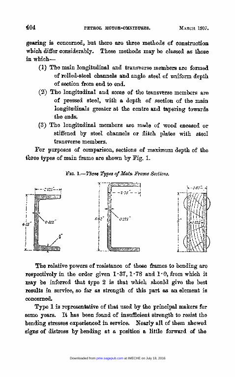
gearing is concerned, but there are three methods of construction which differ considerably. These methods may be classed as those in which-
(1) The main longitudinal and transverse members are formed of rolled-steel channels and angle steel of uniform depth of section from end to end.
(2) The longitudinal and some of t,he transverse members are of pressed steel, with a depth of section of the main longitudinals greater a t the centre and tapering towards the ends.
(3) The longitudinal members are made of wood encased or stiffened by steel channels or flitch plates with steel transverse members.
For purposes of comprdson, sections of maximum depth of the three types of main frame are shown by Fig. 1.
FIa. I.-Three Types of Main Frame Sections.
The relative powers of resistance of these frames to bending are respectively in the order given 1.37, 1.78 and 1.0, from which it may be inferred that type 2 is that which should give the best results in mrvice, so far as strength of this part as an element is concerned.
Type 1 is representative of that used by the principal makers for some years. It has been found of insufficient strength to resist the bending stresses experienced in service. Nearly all of them showed signs of distress by bending at a position a little forward of the
at IMECHE on July 18, 2016pme.sagepub.comDownloaded from
front end of the omnibus body, and it is obviously the part of the frame which would most severely feel the bending efforts and efforts productive of contrary flexure. IR front of this critical part of the frame the load is distributed between the points of attachment of the front springs, and behind it considerable stiffening effect is obtained by fixing it to the comparatively rigid OdbU8 body. The severest bending stresses undoubtedly occur when a fierce clutch is suddenly dropped in, or when the brakes are instantaneously applied, and sggravate the effect of the pitching that may be observed when the omnibus is travelling over a bad road surface. Nearly all these frames have now been stiffened or reinforced, either by the use of truss-rods or stiffening plates of various forms.
The type of frame represented by No. 2 has not been so much used as No. 1, but it has been adopted by at least one maker of great experience. There is a growing tendency to use it, although it is a more expensive form of construction than the heavier form represented by No. 1. From the point of view of reduction of weight and oorrect use and ilisposition of the muterial, it is an improved form, but as a deeper section of lighter scantling is employed the junction of frame-members have to be very well deeigned and made to resist loosening by working or bulging and tearing away. Some of these frames now in use and made in France are showing signs of distress as before, by bending of the longitudinal members.
The type of frame represented by No. 3 has been used with only three types of omnibus, but the particular form shown has proved to be very successful as used with the De Dion omnibus, Plate 26. Its strength, judged merely from the section and with the combination of materials taken into consideration, is much less than either of the other types, but there is no doubt that it is a livelier or more elastic frame and oapable of undergoing greater deflection than the other types before deformation occur8. A frame that is rigid, or is of a section from which little deflection can be expected without permanent change of form, must be of greater weight than the more flexible frame, and for these reasons the armoured wood-frame is good.
2 1 2
at IMECHE on July 18, 2016pme.sagepub.comDownloaded from
Two exemplea of rolled-steel frame construction are shown by Plates 94 and 25, as used with the Straker-Squire and the Dennis omnibuses. In the former the reinforcing plates referred to m y be seen in the plan ; and in both types the form and arrangement of the transverse members are shown, and the nature of the attachments to the longitudinal members. In both these designs it will be seen that B secondary frame, hung from the main frame, carries the engine and change-speed gear-box. In Plate 24 the position of this frame is indicated at D, and in Plates 25 and 26 at H.
Plate 27 shows the pressed-steel frame as used with the Milnes- Daimler omnibuses. In this design the material has been disposed to the greatest advantage, and it is interesting to note that in some ways parts of the framework aro satisfactoriIy used for two purposes. It will be seen, for instance, that the dished stiffening plate, extending from the forward end of the frame to the back end of the gear-box, reinforces, and also forms part of the means of support of the engine and change-speed gear-box, and partly takes the place of the undersheathing below the front part of the frame. There is not much provision in any of these frames for racking or corner streases, but such provision as is made by the use of Webb or guaset plates at angle junctions appears to be sufficient for the frames of lighter automobiles, but not for heavy omnibuses.
With the exception of the sagging of the frames referred to, nearly all of the types in use have resisted the constant twisting and working to which they are subjected without pronounced trouble by loosening of rivets and bolts at the joints, and have indeed only given wsy in this respect as a result of bad workmanship. There are very few frames so stiffly constructed that some twisting or elastio flexure cannot occur, nor is i t desirable that they should be; but it is desirable that this flexure should be fully recognised and provided for in the machinery attached to them.
Even in some of the best motor-omnibuses the connection between the clutch-drum or shaft and the gear-box shaft is by rigid coupling, just as though these parts were fitted to a heavy rigid bed-plate like that of a direct-coupled central-station engine and
This necessity is far from being generally met.
at IMECHE on July 18, 2016pme.sagepub.comDownloaded from
dynamo. In this latter case it is necessary or at least could not be harmful. The engine or the dynamo are never or seldom moved from their bed, and if they are, they are put back again carefully with time, light, and every requisite for accuracy.
I n a motor vehicle the case is very differenfi. Its bed is light and flexible, and it is dancing and jolting over bad roads all day long. There is relative motion between shaft and gear- box Shaft, and the engine may not only be taken off its bed several times in the year, but the engine may be changed more than once in a year, and generally in double-quick time. I f it is not aljsolntely in line in every direction, as i t should be, with the gear-shaft, i t has to accommodate itself as well as it can, when the bolts of a rigid coupling are pulled up tight. It does this in various ways. Sometimes it has an unbendable will snd breaks something, but more often it struggles on until it has scooped out the bearings for the pleasure of freedom, or it wriggles the coupling- balk to pieces. This means then that a coupling that will give freedom without looseness should be employed at this place, and at other places whenever B rigid thing with working parts is h a to a flexible frame. Universal couplings or Hook’s joints used for this purpose may be seen at E in Plates 25 and 26.
The whole weight of the omnibus is invariably supported upon the axles through leaf springs of semi-elliptic form. Connection of the front springs to the frame is usually made at the forward ends by a simple pin-atbchment, and at the rear ends by shackles or swinging links. The rear springs are, with very few exceptions, connected by shackles or equivalent sliding junction-pieces to permit of movement to the front or back of the axle position, without longitudinal displacement of the axle in relation to the frame. In a few caws a transverse spring has bean used at the rear of, and in connection with, the side pair of rear springs, but this arrangement is now infrequently used, and has generally been found to provide too great a range of spring deflection, and has tended to increase the lateral movement by swaying of the omnibus on the springs. It ie a three-pint method of suspension instead of the commonly employed four-point method with two springs. An example of the
at IMECHE on July 18, 2016pme.sagepub.comDownloaded from
use of three springs at the rear axle is shown, as used with the Dennis omnibus, by Plate 25, the transverse spring being at D below the double-transverse channels.
Axles.-The axles used are of varying form, but generally of similar type at the front to permit of the use of pivoted axle- ends. The pivoted form of axle is required as part of the universally used Ackermann type of steering-gear, by means of which a large steering angle or lock is conveniently obtained with the necessary rnnning clearance between the frame and wheels when the steering angle is considerable. As shown by Plate 25,
FIG. &--Three Forms of Axle-end.
the steering angle obtained is 30 degrees and the turning circle of the omnibus is 55 feet, that is to say, the omnibus could, if required, be turned in a road 55 feet wide between the kerbs. To obtain this steering angle, it is usually necessary to reduce the width of the frame at the front, as indicated in the plans of several of the under-carriages shown, but the better designs use a straight frame throughout of the narrower width.
In most designs of front axle the ends are forked to receive the pivoted-wheel axles, as in the original Ackermann design, but occasionally the method is reversed, the pivoted-wheel axle being forked and the centre fixed part of the axle formed with pivot ends. Fig. 6 shows examples of three forms of axle-end. They are
at IMECHE on July 18, 2016pme.sagepub.comDownloaded from
fypical of those used with, for instance, the De Dion, Milnes- Daimler, and Straker-Squire omnibuses respectively. Either form is perfectly satisfactory, provided the combination of dimensions, material, and workmanship is good. Generally it would appear that the wide fork is to be preferred, because less heavy stresses are felt by the pivot-pin; and when wear has occurred, there is less lateral. freedom of the wheel and interference with steering.
The construction of the rear axles is more varied, because of the different firms of transmission gearing employed; but the common forms may be divided broadly into two types :-
(1) Those which are load-bearing and driving axles or live axles.
(2) Those which are fixed and are load-bearing axles only. The former type, although frequently used with heavy slow-
moving motor vehicles, has been seldom employed for motor omnibuses. Used with some forms of transmission gear it is the simplest form of de, but it has to withstand a complex oombination of stresses, and must be of large size to be safe. It possesses one advantage, namely, that the road wheels may be easily removed, and with the least disturbance of parts or bearings,provided that the interchangeability of wheels and axles has been studied.
With live axles or gear-driven axles there is some difficulty in securing suflicient strength under heavy loads with anything like moderate frictional resistances, especially when the distance between the wheel centre and the point of application of the lad, that is, the position of the springs, is considerable. In some OBBBB
the interposition of the brake-drums between spring and w h d enlarga this distance, but it is reduced to a minimnrn in the Milnes-Daimler, in which the brake is applied to a narrow V groove on the wheel rim. In some others the distance between wheel and springs adds a bending moment to the axle, which,with a heavy form of central-gear drive, differential and case, raises the statia and inertia stress to a very high one, and calls for great stre& and weight, which is carried by the tyree and not by the springe.
at IMECHE on July 18, 2016pme.sagepub.comDownloaded from
For a given load on the road wheel, the bearing of a live axle is at a disadvantage as compared with the bearing surface inside the wheel on a fixed axle. In the labter the pressure upon the journal in the wheel is simply that due to the load on the axle or that carried by the wheel. With the live axle the journal pressure is greater than this in proportion to the distance of the bearing in which the live axle revolves from the centre of the wheel.
The fixed or load-bearing axles may be subdivided into two classes :-
(1) The solid straight or bent-bar form, independent of or not connected with the driving gear.
(2) The hollow form containing and providing bearing support for the driving shafts.
These two classes of axle are those now most used; in fact, they are almost exclusively used. The simple fixed load-bearing axle is to be preferred, whether of the solid or tubular form, because apart from the advantage of division of the work of driving and of weight-carrying or resistance of road shocks, no mechanical disadvantage attends their use.
The removal of the road wheels for examination or repair of either the wheels, tyres, axles, or driving gear may take longer than with the simple load-bearing and rotating axle, but it has to be remembered that, with the forms of driving gear which may be employed with the latter type of axle, more time has to be expended in removing parts of the driving gear within the axle housings or casing. It may also be remarked that with the tubular forms of fixed axle used with, for instance, the Dennis and the Scott-Btirling vehieles, Plates 25,28, and 29, the road wheels may be as easily removed as with the rotating load-bearing axle, and the driving gear is similarly enclosed. With the type of axle and transmission gear shown in Plate 27, the objcctions which obtain to some others in this respect do not exist.
The repairs to road wheels and tyres constitute a not inconsiderable proportion of the work of upkeep of the omnibus; and facility of removal and replacement of these parts requires careful consideration. With the designs of axle used, with one
at IMECHE on July 18, 2016pme.sagepub.comDownloaded from
exception, with all types of under-carriage, excluding those which are side-chain driven, a considerable part of the weight of the driving gear is added to the axle and is directly supported upon the tyres, without relief from the effect of road shocks such as may be afforded by spring support. By the use of chain driving-gear the dead weight or weight not spring-borne is as far as possible reduced, and to the relief of the driving gear from road shocks has to be added the relief of the wheels and tyres. Attention may well be directed to the type of axle and arrangement of h a 1 driving-gear, Fig. 9 (pa@ 412), adopted by Nessrs. De Dion et Bouton for their omnibuses. By utilizing their well-known form of jointed driving- shafts, they have been able to employ a simple curved bar or tube axle and enclosed toothed driving-gear, without exceeding the dead weight on the axles of the side chain-driven omnibusea.
Some consideration will be given later to the different types of hal transmission gearing ; and in now referring to frames, springs, axles, and road wheels, no further reference wi l l be made to driving gear. As affecting the question of axle weight, it may be interesting to record that with the 8traker-8qoire omnibus the weight of the axle complete with wood wheels, springs, and part of the weight of the radius-rods and driving chains, is 124 cwts. With the gear-driven Milnes-Daimler omnibus the corresponding total weight, including part of that of the reach-bars and propeller- shaft, is about 23 cmts. With another type of gear-driven omnibus, the Dennis, the total weight, including part of tho weight of the radius-bars and propeller-shaft, is 16 cwts. These figures snftice to show that there may be considerable difference of dead weight upon the wheels and tyres.
Stoutly constructed wooden wheels of the Hancock pattern are most largely 4. Wheels made of cast-steel in one piece are now prinoipally used with the Milnes-Daimler omnibus, and composite mood tand steel wheels with the Crossley, Leyhd, or Lancashire vehicles. The composite wheels have hollow-spoked, cast-steel centres and wooden felloes. Although at present infrequently used, their form and appearance are good. The wooden wheels, when thoroughly well made of the best material, last well, and
at IMECHE on July 18, 2016pme.sagepub.comDownloaded from
they have been, until recently at all events, lighter than the d i d metal and the composite tyres. The production of the one-piem casbsteel wheels referred to is confined to very few makers.
The rubber tyres are now almost uniform in section, and double or twin tyres are used on the rear wheels. From time to time attempts had been made to substitute wood and other materials for rubber, but so far without success. Failure has also attended many attempts to use spring-backed or cushioned wooden-block tyres, and the use of spring wheels has not passed the experimental stage.
Engines.-The petrol engines now made are all of the four-cylinder vertical type. A few of the two-cylinder horizonta1:engines are still i n me, but they must be considered obsolete in type, and their makere now show preference for the vertical kind. I t must,*however, be remembered that a number of omnibuses with horizontal engines, some of them in London, have been in use a considerable time with verg satisfactory records. The vertical engine may be more conveniently placed in the frame of the under-carriage than the horizontal type, and i t permits the most convenient arrangement of the other machinery parts. The longitudinal position of the engine- shaft involves an undesirable right-angle change of direction of drive with present designs of omnibm, but with most of them little trouble can be attributed to this cause. So far as the general design of the modern engines is concerned, fitness for their purpose very largely depends upon quality of material and soundngss of work, and upon the readiness with which the active working and wearing parts can be removed and replaced. It is further necessary that the engines should be very substantially constructed or stiffly built to withstand the repeated fluctuations of speed and load. Besrings and all rubbing or working surfaces must be everywhere of more ample dimensions than those commonly employed for motor-car enghes, and the crank-shaft and connecting-rods require to be of very strong form, though the weight must be kept down to theminimum. Differenceof general design of the engines is now principally con6ned to the grouping of the cylinders and to the
at IMECHE on July 18, 2016pme.sagepub.comDownloaded from
difference of form of the crank-shaft and the crank-chamber which the use of cylinders, cast in pairs or separately, calls for.
The system of valve operation also considerably influences general design, as may be gathered from a brief inspection of the engine drawings shown by Plates 30, 31, and 38. These engines are of types now Very largely used of 24 to 30 B.H.P., but in each case the more modern designs for the higher powers show some differences in detail. Drawings of the most recent details were not obtainable, and are not here required, as the changes which have been found desirable wil l be referred to. Experience again shows that the successful running of the engines is largely determined by the type and arrangement of the important auxiliary parts used in connection with the carbhrettor and petrol supply, and with the water-cooling lubrication and ignition systems. I t is in the design and arrangement of these parts that the greatest difference of practice is to be observed, and to which the greatest interest attaches.
Carhul.ettors.-As primarily affecting the power developed by the engine, some reference will first be made to the form of the carburettor commonly used.
Fig. 13 shows the form employed with the large number of engines now in use with omnibuses of the Milnes-Daimler, and the Straker-Squire, or Bussing types. Air entering the jacket E at D, and warmed by contact with that part of the hot engine exhaust- pipe F within E, passes through the connecting-pipe G to the carburetting chamber C. Unwarmed air may be admitted at H varying in quantity according to the set opening of the disc- shutter H. Petrol is supplied at A to the box By and is there maintained at a constant height and about level with the top of the nipple C. Tinder the influence of suction from the engine, a jet or spray of petrol issues from the nipple, and mingling with the air passes by way of the throttle-valve J and inlet-pipe I@, to the inlet- valves, and so to the engine cylinders.
By restriction of the passage-way at the position of the top of the jet C, the rate of air-flow at that point is increased and greater
at IMECHE on July 18, 2016pme.sagepub.comDownloaded from
suction or ejector effect occurs. The velocity of flow, when the throttle-valve J is open, is high, and at C may roach 6,500 fwt per minute. At the high rate of 00w of air through the carburettor a very h e air-petrol mist is produced, and at the low speeds of flow corresponding to low speeds of revolution of the engine, a sufficiently rich mixture is obtained to permi6 steady running of the engine. If
FIG. 13.-&rhrettor (Straker-Squire).
Tprnlrt mvt3 f-*u
difficulty is somotimes experienced in starting the engine, carburation of the air may be assisted by injecting a little petrol through the cock L at the top of the inlet pipe. The float chamber B is not shown in section, but it is of the commonly-used form with float and small pivoted levers to regulate the lifting of the central needle- valve and the rate of flow of petrol past it, in order to maintain the constant level. Hinged bolts K are used to connect J and the intermediate piece to C. These parts may be quickly removed to
at IMECHE on July 18, 2016pme.sagepub.comDownloaded from
expose the nipplo C whep carbiirettor troubles occur. This carburettor is of simple form, and equalization of the quality of the mixture supplied to the engine at varying rates is not attempted.
With the carburettors * used with some recent designs of omnibus an auxiliary air-supply is arranged, either controlled by the engine speed-governor or by variation of suction at different engine speeds. The position of the type of carburettor illustrated may be seen by reference to Plates 30 and 31. A device for averaging the pressure in induction-pipe, jet-chamber, and float-chamber, is now being used with considerable promise.
Among the most frequently recurring causes of stoppage of the engine is interruption of the petrol-supply, due to a variety of causes. When the supply to the carburettor is by gravity or difference of level of the tank and carburettor, failure of supply is generally due to either insufficient head or difference of level, or to choking of the pipe, and sometimes breakage of the pipe at the upions occurs. When however the supply to the carburettor depends upon maintenance of pressure in the petrol tank, i t is also necessary to keep all joints in the pressure and feed-pipes and at the tank air- tight, and to ensure that the non-return valve at the engine end of the pressure pipe is in proper order. The possible causes of interruption of supply are thus somewhat more numerous when the pressure system, instead of the gravity system, is adopted. With the former system the supply tank may be carried at a distance from the engine at a lower level and in a convenient position for filling, generally under the: frame at the rear of the vehicle. As a rule, however, the usual position of the tank with the gravity system, namely, under the driver’s seat, is convenient enough for filling, and the connection to the carburettor is short, as may be seen by reference to Plate 24, and to Plate 28 where the tank is shown at W.
Water-CooZers.*-Nearly all motor-omnibus engines me provided with a pump of some kind for rapid circulation of the cooling water
* It would be out of place here to deal with carburation and carburettors and coolers generally, but reference on the subject may be made to I‘ Motor Vehicles and Motors,” Vol. I, chap. xvi, p. 320; YO]. 11, chap. xxiii, p. 519.
at IMECHE on July 18, 2016pme.sagepub.comDownloaded from
through the cylinder-jackets and the radiator water-cooler. It is not however now a necessity, and the circulating pump should be discaxded; firstly, because it is a working part which can be dispensed with; secondly, because its us0 gradually destroys the effectiveness of the cooler, by coating and even choking the cooler tubes with the oil and grease which has to be used to lubricate the pump; and thirdly, because a pump almost of necessity introduces a leakage point, and magnetos are injured by water. Noreover it is always desirable to have a head of water above the top of the cylinders. The radiator water-coolers are either of cellular construction, or the exterior surface of gilled tubes forms the air- cooled surface. Although the best made cellular or honeycomb types of radiator have resisted vibration extremely well, they are difficult to repair when they become leaky, and in this respect they compare unfavourably with the gilled-tube radiator.
Large cooling surface is obtained by the honeycomb construction, but it is very questionable whether so large a proportion of that surface is as effective as is the surface in a well-construcbd air- cooled tubular radiatbr. Moreover, after a short period of me, especially in some districts, slight incrustation of the interior surface by deposit from the water not only reduces the efficiency of the cooling surfaces, but in the honeycomb form this incrustation is difficult of removal. This defect is aggravated when oily deposit from a circulating pump occurs.
As an example of the use of the thermo-syphon or natural system of circulation of the cooling water by temperature difference, reference may be made to Plates 28 and 29. The cold-water supply- pipe from the bottom of the lower part of the radiator G to the lower part of the cylinder jackets is at J, and the heated water from the top of the jackets rbturns by separate pipes H to the upper part of the radiator. A belt-driven fan behind the radiator is used to maintain s flow of air through it to increase thecooling effect. With some engines the fly-wheel arms are formed as fan-blades, and a fan behind the radiator can then be dispensed with, if the engine - bonnet and undersheathing are made reasonably air-tight.
at IMECHE on July 18, 2016pme.sagepub.comDownloaded from
Ignition.- Magneto- electric systems of ignition are most frequently employed with the engines, and of the low-tension more often than the high-tension type. The accumulator and induction coil high-tension system is occasionally used, sometimes as the main system of ignition, and in a few instances as a supplementary or secondary set to be used for starting or when the magneto system is out of order. With the low-tension magneto system the insulated stems of the igniters on the engine cylinders are always electrically connected, either by a collector-bar and single lead or by separate leads to the magneto generator.
Fig. 14 shows the design of igniter used for several years with the Milnes-Daimler engines, and it is representative in principle of those used by other makers. The fixed insulated stem is shown at A, and the moving contact stem at By both projecting into the cylinder combustion-chamber. The striker-rod C is normally in the position shown, and the upper headed end, by contact with the outer arm of tho moving stem 3, forcibly prevents the inner arm from making contact with the inner end of A. On a gear-driven cam-shaft within the engine crank-chamber are stepped cams, which give movement at the required moments to the striker-rods C. Shortly before ignition is to take place the cam slightly lifts the rods C through an intermediate pusher-rod, not shown but immediately below C, and the light spring D may then rotate the stem By through the small arc necessary to permit contact of the inner arm on B and the end of the stem A. The stepped part of the cam then passes the foot of the pusher-rod, and allows the rod C to drop sharply under the influence of spring E. The momentary completion of circuit is thus followed by B quick break and arcing, or sparking across the igniter stem ends at A and B.
The timing of ignition with the form of igniter described is usually fixed as to period with no adjustment to suit high or low engine speeds. The proper use of ignition timing-gear is to be encouraged, but i t is at present difficult to ensure correct regulation of ignition by the driver, and some makers continue to fix the period of ignition permanently.
High-tension magneto generators are becoming more frequently used, but they almost without exception require more mechanical
at IMECHE on July 18, 2016pme.sagepub.comDownloaded from
improvement than the low-tension type. They may be looked upon as taking the place of accumulators as 8 source of current, and they are sometimcs the equivalent of accumulators, induction coil,
FIG. 14.-Igniter (Milnes-Daimler).
D-
-A
C
U
U
A. Fixed insulated
B. Semi - rotating contact. stem.
C. Striker-rod.
D. Contact-making
E. Contact-break- ing spring.
condenser, contact maker or breaker, and high-tension current distributor. With high-tension magneto ignition, sparking plugs, very similar to those used with the accumulator and induction
2 a
at IMECHE on July 18, 2016pme.sagepub.comDownloaded from
coil system, are used, and provision is generally made for adjustment of the period of ignition. Magnetos, although small, are subject to working-pressures in their bearings which are not always small, but these bearings and journals are nearly all made of dimensions that suggest toy-shop origin rather than a full appreciation of their intended use, wherc they will be called upon to do continuous work very far removed from play and ought to be in good condition at the end of a year, after making about a million revolutions per day.
Lubrication.-Until recently lubricators of various forms have been used, from which a variable quantity of oil was allowed to gravitate through small-bore pipes to the different points of the engine to be lubricated. Small hand-worked oil-pumps were also provided to allow the driver to add readily to the quantity of oil in the crank-chambers, when there was reason to believe the quantity already there to be insufficient. These sight-feed lubricators with numerous drip-tubes and adjustment sorews have been largely dispensed with, and in many omnibuses only two or three drip-tubes have been retained or found desirable.
As far as possible, lubrication of the parts of a motor-omnibus, or indeed any motor-vehicle, should be automatic and continuous, and much may be said in favour of the forced lubrication system now being gradually adopted. This method of lubricating has been in use with the De Dion and Maudslay omnibuses for some time, and has been successfully used for many. years with the Belliss and Morcom types of high-speed steam-engines, for which purpose it was originally devised and used by the late Mr. Morcom. By thiR means copious lubrication of all actively working parts may be ensured, without necessarily repeating the effect of over-lubrication by the gravity and splash-bath methods. The system of forced lubrication used with the De Dion engines may be seen by reference to Plate 32. The oil-ducts to the crank-shaft bearings are shown at K, but passages through the crank-webs for lubrication of the crank-pins are not shown.
Inlet and Exhaust Vahe8.- Without unduly prolonging the reference to engine details, it may be pointed out that an interesting
at IMECHE on July 18, 2016pme.sagepub.comDownloaded from
difference of construction of those engines, illustrated by Plates 30 and 31, lies in the methods of operating the inlet and exhaust valves. In the Straker-Squire engine it will be noted that a vertical skew- gear-driven shaft H gives motion through similar gear J to a longitudinal horiaonhl valve-acting cam-shaft C above the cylinders. Valveoperating levers, pivoted at the sides of the trough within which the cem-shaft works, give downward and opening movements to the upwardly projecting valve-stems of the inlet and exhaust valves arranged at opposite sides of the cylinders. This is a method less frequently used than that exemplified by Plate 31 representing a Milnes-Raimler engine. Here spur-gear-driven cam-shafts h and B within the crank-chamber C are separately used for operation of the inlet- and exhaust-valves D and E arranged at the opposite sides of the cylinders. The inlet cam-shaft A on the right-hand side of the engine also osrriea the cams for operation of the igniters, described with reference to Fig. 14 (page 419). Both these engines have four- throw, three bearing crank-shafts, and cylinders caet in pairs, but several types of engines in use have four-throw, five bearing-shafts and separately cast cylinders, as shown by, for instance, the De Dion engine, Plate 32.
Objection may sometimes be raised to the depressed seating given to the valves, especially the exhaust-valves of some engines. The cylinder dimensions of the 20 to 24 H.P. engines shown are 4& inches bore (105 mm.) and 54 inches stroke (130 mm.), but larger engines of 28 H.P. are now used having cylinder dimensions of 4& i n o h bore (110 mm.) and 5fr inches stroke (140 mm.). The normal speed of revolution is about 900 revolutions per minute.
Friction Olutches.-With four of the representative types of under- d g e illustrated, leather-faoed cone friction-clutches are nsed, and they continue to be the type most largely employed for transmission of the power from the engine to the driving-gear. They generally take the form of that shown by Figs. 15 and 16 (pages 422 and 423), or they may be of reversed form commonly known as the internal spring presaure balanced type with the directions of movement for engaging or disengagihg the opposite of those required with the type illustrated.
2 a 2
at IMECHE on July 18, 2016pme.sagepub.comDownloaded from
These two forms equally possess advantages and disadvantages, and there is little reason to adopt one in preference to the other. The clutch-cone as shown by Figs. 15 and 16 may be removed with little disturbance of other parts. Provision for easy removal of tbe clutch is always necessary.
FIG. 17.-Disc Glutoh (De Dion).
A. Engine crank-shaft. B. Fixed friction-plate (c.i.). '2. Sliding friction-plte (c.i). D. Clutch disc (hard steel). E. Disc - shaft transmitting
power to driving-shaft. F. Disengaging levers. a. Disengaging pins. H. Engaging or load springs. J. Fixed transverse shaft
carrying operating levers. K. Operating levers.
K L. Protecting cover.
A
I n s . 0 1 2 3 4 5
Clutches constructed entirely .of metal and running in oil have been used with very few types of omnibus. That used with the De Dion et Bouton omnibuses is shown in section by Fig. 17. It is of the single-disc type with two pairs of friction faces ; and it will be seen that the effort of spring engagement is balanced or self-contained. Multiple-disc clutches have been used on some
at IMECHE on July 18, 2016pme.sagepub.comDownloaded from
motor-omnibuses, and are being used on some that will be ere long running in London and elsewhere. They are all made on the principle of the Weston clutch,* in which the pressure on one pair of surfaces is brought to bear on any number of suoh pairs, thus making a given pressure effective over any multiple of pairs of surfaces. Some of these clutches have been used with grooves on the one face and ridges on the other fitting in the grooves as described by Professor Hele-Shaw t before this Institution, but nearly all are now being made with flat steel annular discs.
Change-Speed Gear.-The forms of change-speed gear employed are all similar in that the engagement of pairs of toothed wheels is effected by axial sliding or by side-meshing them. Except for this general similarity they differ in innumerable details as to arrangement, number of wheels, type of bearings, operating gear, form of box, and materials of construction. I t may be at once admitted that to deal adequately with the details of these transmission gears a separate Paper is required.
An interesting form of gear and one that is largely used is that shown by Figs. 15 and 16 (pges 422 and 423). The wheels shown provide for four speeds, forward and reverse. Attention may be directed to the form of the short stiff shafts D and E, the types of ball-bearings, and the form and method of securing the gear-wheels to their centres. Those who are not familiar with motor-vehicle construction will no doubt particularly notice the extreme lightness of the cast-iron gear-box and indeed the small dimensions of all parts. Judgment can only be pronounced as to the sufficiency of these dimensions, after careful consideration of the nature of the materials employed and the stresses to be resisted.
Gear-Boseu.-Other forms or gear-boxes are shown by Plates 24, 25,26,28,,and 29, and Fig. 18 (page 428), and it will be seen that there is a remarkable difference of size of the containing boxes. The arrangement of shafts and gear-wheels in the gear-box shown
* Pmceedinge, 1868, page 214. t Proceedings, 1903, Part 3, page 483.
at IMECHE on July 18, 2016pme.sagepub.comDownloaded from
on Plate 25 is such that, by using a divided primary shaft, two pairs of gear-wheels are required for the greater speed reductions. For the highest speed of the omnibus, when the least gear reduction is required, the parts of the primary shaft are connected by jaw- clutches. The power is then transmitted through the gear-box by the equivalent of a single straight shaft; none of the gear-wheels are active, but are idly driven, including those on the secondary sbaft ; and frictional losses in the gear-box are reduced as long as the top speed, or direct drive, as it is frequently termed, is in use. When any of the other gears are engaged, the frictional loss is probably greater than that occurring with the type of gear-box shown by Figs. 15 and 16 (pages 422 and 423), inasmuch as the power is transmitted through two pairs instead of one pair of gear-wheels. With the Dennis gear-box the arrangement of the top speed jaw- clutch is such that simultaneously with its engagement the gear- wheel, on the rear end of the primary shaft, which at the lower speeds always transmits the power,is moved out of mesh with its pinion on the lower or secondary shaft. There are then no gear- wheels in mesh, and the secondary shaft and the wheels carried by it are stationary. When it becomes necessary to change from the top speed to the next highest speed, the stationary secondary shaft has to be accelerated up to proportional speed, by re-engagement or side- meshing of the final pair of gear-wheels referred to.
In these gear-boxes there are only two shafts, or if the divided shaft is regarded as two shafts, only three shafts with their toothed wheels, and there is in addition a short spindle or shaft carrying one and sometimes two pinions used in the train required for reversing. Referring to Plate 24, it will be seen that two gear- boxes are employed, the first, that at A, containing the change- speed gear, and delivering the drive through the propeller-shaft C to the second gear-box B. I n this second gear-box there is a pair of bevel wheels at B, by means of which the right-angle change of direction of drive is effected, and a pair of spur-wheels for a further stage of gear-reduction. The larger of the spur-wheels surrounds the differential gear through which the power is equally delivered to chain sprockets at the ends of the divided transverse shaft. In
at IMECHE on July 18, 2016pme.sagepub.comDownloaded from
some forms of gear-box, notably that used with the Durkopp and De Dion omnibuses, the change-speed gear, and bevel and differential gears are all contained in a single gear-box, thus forming a single complete transmission gear unit, the only separate and exposed gear being, with the Durkopp omnibus, the chains and chain-wheels for the final drive to the road-wheels. Figs. 18 and 19 (page 428) show the change-speed and differential gear-box of this type used with the De Dion omnibuses. The driving pinion 0, Fig. 18, gears with the large bevel wheel L, Fig. 19, so that although separately shown the position occupied by the differential gear may be judged by reference to these views and to Plate 26. For forwird running, power is transmitted from one of the pinions on the upper shaft to one of the corresponding wheels on the lower shaft, the six gear-wheels shown providing for three forward speeds. Only one pair of change-speed wheels is engaged at any time, but necessarily a train of two wheels is also included for reversing at low speed.
Interesting features of this gear-box include the use of an oil- circulating pump C, Fig. 18, for the continuous supply of oil to the spindle bearings and gear-wheels. The oil is filtered and freed from small solid particles before re-delivery to the bearings, and thus one common cause of rapid wear and destruction of bearings is removed. The differential gear is of the spur-wheel type, instead of the more frequently used bevel-wheel type.
Power delivered finally to the universal joints at E, Plate 26, and Fig. 19, is transmitted through the jointed shafts J to the driving pinions of the internally-toothed gear shown in Fig. 9 (page 412).
Power Transvn&s~on.-&ny methods of transmission of power from the change-speed gear to the driving road-wheels are in use, requiring the use of different types of gearing. Some of these types are completely enclosed and bath-lubricated, others are semi-enclosed and lubrication is not copious, while some are not protected at all, are exposed to weather and road dirt, and only receive intermittent lubrication. The satisfactory performance of all the forms of
at IMECHE on July 18, 2016pme.sagepub.comDownloaded from
gearing used depends very much upon the attention given to protection from dirt, and to the thorough lubrioation of all active parts. Although quietness of running and smooth working largely depend upon careful construction and workmanship, yet the freedom from noise so conferred will be of short duration if insufficient consideration is given to the lubrication and protection of a11 working parts. Rapid wear of active parts has however occurred even when these matters have had the necessary attention given to them, but the causes of such wear and breakage have been referred to in the early part of the Paper. Reviewing the forms of final transmission gearing now employed, it may be remarked that the greater number of types of omnibus are provided with side chain- driving gear, as compared with the many forms of gear driving, but that considered numerically the greater number of omnibuses in use are provided with gear drives of several types.
The !3traker-Squire vehicle already referred to is representative of those driven by side chains ; but i t may be remarked that so far the only attempt to proteot the chains by encasing them has been practically carried out in the Arrol-Johnstone vehicle. At present the noisy working of the roller ohains generally used has led to the experimental use of chains of the Hans Renold silent type, and the Norse rocker joint-pin chain of very similar external form. It remains to be 8een whether these chains can be economically used when left exposed and intermittently lubricated.
Plate 29 shows the bevel-gear-driven back axle of the Scott- Stirling omnibus partly in section. With this design, protection and lubrication of all parts are amply provided fur. The same remark may be made respecting the somewhat similarly formed bsck axle of the Dennis omnibus, Plate 25, and considerable interest attaches to the worm and worm-wheel form of driving-gear first adopted by these makers for the severe work of driving heavy motor-omnibuses. Little priblicity has SO far been given to the results of working of this gear or to the degree of efficiency obtained in transmission, and it is commonly regarded with some suspicion as to economic efficiency, although some omnibuses provided with i t have now been at work for sufficiently long
at IMECHE on July 18, 2016pme.sagepub.comDownloaded from
periods to prove or disprove the advantages expected to result from its use.
Various arrangements of spur-gearing final drive are to be seen, and are now largely used with the omnibuses at work in London. The particular type here illustrated by Plate 27 and Fig. 20 (page 431) has been most frequently used, and is that used for at least eight years by the makers of the Milnes-Daimler vehicles. The De Dion Bouton, Ryknield, and Eugene Brilli6 omnibuses are provided with final driving gears of similar form, but with intermediate gear of different type. Many of these gears have been run with no protection whatever and with little or no lubrication, and they have consequently been noticeably noisy after use. When this form of gear is well made and run under satisfactory conditions, its quiet running and freedom from wear have been remarkable. Fig. 9 (page 412) illustrates the De Dion driving-gear, but the method of protection from dirt by encasing is not completely shown.
Referring to Fig. 20, it may be remarked that the Canstatt (Milnes-Daimler) differential gear is the only type in use with the two halves of the differential so placed that they may not be in line but at say 177", and so that they have a downward inclination from the centre at which they meet. The useful object of this is that the road-wheels driven by this differential shaft may run on an axle with a similar downward deflection and the wheels be slightly coned. By this means the wheels have always a tendency to run on to the axle, instead of pressing outward with a tendency to run off, and wear out the washer on the end of the axle and the nose of the nave. There are also other reasons, which however do not press so much in these days of metallic wheels.
With the De Dion omnibuses the road wheels are inclined slightly, and the downward inclination of the driving shafts is permitted by the use of the universal joints already referred to.
Little consideration has been given to spring-cushioning or relief of the transmission gear by means of buffers or cushions of some sort. One of the first and also one of the best methods that have been used is sufficiently shown by Plate 24. The driving effort, it will be seen, is there taken through draw-bars F, and delivered
at IMECHE on July 18, 2016pme.sagepub.comDownloaded from
through volute springs to brackets fixed to the main frame. TO permit movement of the draa-bars tho rear ends of the forward radius-rods E are slotted, which allows sufficient movement for spring relief, but advisedly limits the range of such movement.
FIQ. 2 I .-DiferentiaZ-8haft Brake (Milnes-Daimler).
Various designs have been made of motor-omnibuses with the front wheels driven and the back wheels as trailers, Although it is practicable to make a front-drive vehicle which might be used for level running, the arrangement has an inherent mechanical defect.
at IMECHE on July 18, 2016pme.sagepub.comDownloaded from
The propulsive effort is in part resolved into a vertical or turning effort about the centre of rotation of the whole, resulting in an increase of the load effect on the back wheels and a decrease on the front wheels. The frictional adhesion is therefore so lessened that acceleration from rest is reduced and hillclimbing troubles increased. Rspid acceleration is more or less a necessity for motor-omnibuses for London use, and rear-wheel propulsion would seem therefore to be a necessity. I t may be here mentioned that the same fore and aft tilting effort, but in the opposite direction, occurs on the application of the brakes, and hence the distance witbin which retardation from velocity X to velocity 0 is possible is greater than the distance within which acceleration from velocity 0 to velocity X may be obtained.
Brakes.-Brakes for any motor-vehicles, and perhapa it may be said especially for motor-omnibuses, are amongst the most important of the details. In almost all the omnibuses at present running, the brakes chie3y used are those operated by the pedal under the driver’s foot, acting on bands or brake-shoes of one type or another, on brake drums attached to one of the gear-box shaftw, or to the transverse shafts of both gear and chain-driven omnibuses. In some vehicles the anchorage of the brake-bands or shoes is carried by a member of the frame as at G and H, Plate 25. By this means the stresses due to the resistance to rotation of the brake-bands is carried by the frame, and the gear-box thereby relieved. These brakes, although on drums of small diameter, are powerful because they are applied to a high-speed shaft, and in many oases are now cast with an internal channel to receive water to keep them cool.
Supplementary to these brakes are those on the driving wheels, and they are of several forms. In most cases they are band-brakes on drums affixed to the wheels, and in some they are internal expanding brakes inside these drums. The internal brake is, for instance, fitted to the vehicles shown by Plates 25, 28, and 29, in which the driving wheels run on a hollow fixed axle. In the form shown by Plate 24, in which the wheels run on a fixed solid
at IMECHE on July 18, 2016pme.sagepub.comDownloaded from
axle and are driven by chains, the sprocket wheel and drum are seen between the road wheels and the springs in the plan. In that vehicle the side brakes are of the internal expanding type, applied by a side lever and equalising links at K, through which an equal pull is given to the two side-rods which run backwards to the brake. A different formof equalising brake pull is shown in the plan, Plrte 29, in which an equalising bar T is pulled from the centre by the hand-lever and the two side rods actuated by it. In some vehicles an exterior brake-band is applied to a drum of the kind shown by Plate 24. Fig. 21 (page 432) illustrates the pinion or differential brake acting upon the drums H, Fig. 20, and it indicBtes sufficiently the type of foot-brake used with several vehicles. Cast- iron brake-drums and brake-blocks are used, and in the example shown there is provision for easy adjustment of the blocks and their easy replacement when worn.
Working Costs.-All the petrol motor-omnibuses dealt with in the Paper are of the same carrying capacity, namely 34 passengers, and hence a nearer approach to the actual working costs can be made than is the case with motor-wagons, for instance, working in different parts of the country in different trades, different length of journeys, and different effective proportion of journeys, varying loads and varying terminal m d stopping-place time losses, working with and without trailers, which give rise to great variation in the relation between cost of working per vehicle-mile and per load ton-mile.
With the petrol motor-omnibus it is only necessary to consider the cost per vehicle-mile. This varies to an appreciable degree with different makes of motor-omnibuses, but this variation is very small as compared with the difference caused by different management. Most omnibus owners started operation with the ownership of little or nothing more than the omnibuses, just as though they were only wheelbarrows and required only a gang of labourers to wheel them, and a ganger to see that they wheeled them. The owners did not understand that they were entering upon an engineering undertaking with an immense quantity of high-class machinery, which would
at IMECHE on July 18, 2016pme.sagepub.comDownloaded from
require more constant care and supervision than was ever before required for any similar quantity of machinery, not even excepting the railway locomotive with its requirements of running-shed and engineering workshops.
Having found that the mator-omnibus would run when delivered to them, they ran them distances and speeds regardless of the difference between the possible and the commercially practicable or expedient. With no repair works and with insnfficient and sometimes incompetent staff, they ran their omnibuses RE many hours as they could anyhow be kept on the road and at destructive speeds. I n no commercial matter has the adage, as to the stitch in time saving nine, ever proved to be so indisputable a fact. The one stitch was seldom made, until the disastrous results of its disregard proved that the motor-omnibus-using company must fully recognise the engineering requirements of the business i t enters upon. This has caused great increase in the cost of maintenance over that which was necessary.
In the latter part of 1905 and early part of 1906, the author estimated the total working expenses of 34-seated petrol motor- omnibuses working a maximum of 90 miles per day at from 8.79d. to 9 Od. per omnibus-mile. Since then petrol has nearly doubled in price, and the unsatisfactory conditions of working have increased the cost of repairs and renewals, and the long mileage per day makes double shift of both driver and conductor, or three drivers and conductors to two omnibuses, necessary. Improvements in the matters affecting repairs and renewals are however being made, and there is every probability that this estimate will be fully collfirmed by all well-managed omnibus services, as it has already been confirmed by some. The increased price of petrol and the extra cost of double shift and of longer mileage must of course be added to that estimate.
The possible cost of working a petrol motor-omnibus of the better makes, under proper conditions and running an average of 100 miles per day for 280 days per year, or 28,000 miles, may now be put as follows :-
2 H
at IMECHE on July 18, 2016pme.sagepub.comDownloaded from
Depreciation at 20 per cent. (allowing for value of 5years) . . . . . .
Driver and conductor . . . . . Tyres, per contract . . . . . . Petrol, or fuel of other name, at 9d. per gal. . Oil and grease . . . . . . Renewals andrepairs . . . . . Wa$hing, stabling, lighting, and sundries . Insurance . . . . . . Supervision, assistants, ticket service, and sundries
. .
. .
. .
. .
. .
. .
. . Total vorking costs . .
Mile. 1.00
2.25 2.00 1 .63 0.25 1.33 0.35 0.40 0.28
9.54 - __ -
The average receipts per motor-bus mile on some routes in London exceed 13d. per mile. The difference between receipts and the now possible cost of working is thus fully equal to the author’s expectations as stated on various occasions.
Conc1uaim.-No standardization in motor-omnibus construction can be expected for some time. The general design of the motor- omnibuses now in use may be said to have been outlined from two to five years before they were developed in detail to the types which began to be used two years ago in any number in London.
The extraordinary mileage, which soon beoame a possibility with them, rapidly accumulated more working experience in a short time than has probably been crowded into a few months with any other type of road vehicle under commercial conditions. The companies started running them, the public immediateIy adopted them in preference to the old horse-vehicle, and the companies were constrained to keep them on the road in spite of the very great diiliculties which accompanied continuous work and continuous necessity for improvements and renewals. The result is now obvious in the great advance which has been made in the last year and a half towards a satisfactory vehicle; but the experience has been very costly, and on the whole i t must be admitted it has proved that even with the finest material ever placed in the hands
at IMECHE on July 18, 2016pme.sagepub.comDownloaded from
of the mechanical engineer, larger dimensions and greater surfaces are required to contend with the severe work of the present double- deck omnibus. Some further improvements, which will secure durability of parts and fewer breakages resulting from loosening of parts, will no doubt be made; but endurance of known materials used under present conditions of working and road surface Cannot be indefinitely extended. Improvement may be looked for in the conduct of traffio that will permit much smaller omnibuses to be run commercially. Then the weight of an omnibus may be materially reduced, and fuel and oil consumption and wear and tear reduced, and these with a general observance of the legal speed limit will together add to the life of an omnibus, to its trustworthiness and to its commercial efficiency. There are now fewer directions in which imagination can point new paths of improvement, but there are still sufficient to make it unwise on the part of purchasers to act as though a standard of design and constru&i~n had been approached.
The author has to thank those who assisted by supplying some of the drawings from which a number of those herein reproduced have been made, and wishes particularly to mention the assistance given in the preparation of the Paper by his son, Mr. E. G. E. Beaumont.
The Paper is illustrated by Plates 24 to 33, and 12 Figs. in the letterpress.
at IMECHE on July 18, 2016pme.sagepub.comDownloaded from
The PRESIDENT was sure the members would agree that the Paper was one of great interest, which was evidenced by the fact of such a large number attending the meeting. He had very great pleasure in proposing a hearty vote of thanks to Bar. Worby Beaumont for his Paper.
The resolution was carried with acclamation.
Mr. A. A. CANPBELL SWINTON thought everyone present must have listened with great pleasure to the Paper, and must have been imbued with the importance of the subject from the figures given by the author as to the enormous number of passengers which were carried at the present time by motor-omnibuses in' London. He would like to be permitted to give some additional figures which, although he had given them before to a different audience, would, he thought, bear repetition. The author pointed out that the motor- omnibuses in London were at the present moment carrying, according to his calculations, 185 million passengers a year. E e (Mr. Swinton) made a calculation some little time ago, and came to the conclusion that the figure was more nearly 200 million passengers a year. What he particularly desired to point out was that, according to a recent statement made by Mr. T. McKinnon Wood, of the London County Council, the figure of 185 million mentioned by the author, or of nearly 200 million according to his own calculation, constituted a larger number of passengers carried by the motor-omnibuses of London per annum than were being carried by the London County Council tramways, the figure for the London County Council tramways as given by Mr. McKinnon Wood being 180 million. He believed at the present moment there were something over 800 motor- omnibuses in London, the cost of which, together with garages and all other necessaries, was less than ~1,000,000 sterling. On turning to the accounts of the London County Council tramways, it was
But he wished to go a little further than that.
at IMECHE on July 18, 2016pme.sagepub.comDownloaded from
found that &5,000,000 had been spent on the tramways system ; so that the result arrived at was that, with one-fifth of the capital expenditure, the motor-omnibuses were carrying more passengers.
The late London County Council proposed to spend another 65,000,000 on tramways ; and he personally asked the new Council to pause and see whether i t would not be better to allow the omnibus companies of London to carry the passengers, and for the Council to save its 85,000,000, or at any rate a large portion of that amount, and expend the balance in improving the roads and other arrangements for traffic in London. He was sure if they would only spend a million pounds in improving the roads, i t would have an enormous effect in diminishing the wear and tear on motor-omnibuses and on other vehicles and the noise the vehicles made. As all who either drove motorars or travelled on motor-omnibnses were aware, the roads of London werc not what they might be.
He thought the author was not quite fair upon the motor- omnibus official ; he seemed to think that the motor-omnibus director’s or official’s ojle aim was t o get as much mileage as possible out of the omnibus, and that he never considered for a moment the keeping of his vehicle in proper repsir. He had hoard that statement made over and over again, chie5y by the manufacturers of motor-omnibuses, who were somewhat interested ; but i t was not a fair statement so far as he was acquainted with motor-omnibus management. It might be the case in one or two very small concerns, but i t was not the case with the larger companies at present running motor-omnibuses. I f the members only knew the amount of money that had been spent, and the amount of trouble that had been taken in keeping the vehicles on the road in proper condition, they would be surprised. I f a visit were paid to any of the larger garages where the motor- omnibuses were housed, cleaned, inspected, and repaired, it would be found they were equipped with the lrstest machine-tools, and that a very competent and skilled staff of engineere was constantly engaged i n keeping the machines in order. He was afraid that the machines up to the present time, although they were being greatly improved, had not been as perfect 88 they might be. No doubt that condition of affairs would improve with time.
at IMECHE on July 18, 2016pme.sagepub.comDownloaded from
PETROL HOTOR-OMNIBUSES. 31ARCIi 1907. 440 (Mr. A. A. Campbell Swinton.)
The author had given some figures with regard to the cost of running motor-omnibuses. He did not know whether those figures were intended to apply to London ; if so, he thought they were too low. The running of motor-omnibuses in London was quite a different thing from running them in the country. Ile could not give any figures for London, for reasons the members would understand. He had such figures, but he had to keep them to himself because there was such a thing as competition in London. He wonld, however, be happy to supply figures for the year 1906 of the costs of running twelve motor-omnibuses in connection with the Bath tramways. At Bath there was a very complete tramway system, and in addition to the tramway system there were twelve motor-omnibuses which ran out into the country and fed the tramways. Of the twelve motor-omnibuses, six mere in their second year of running. The figures were as follows :-
Costs per onanibzas-mile.
Petrol . . . . . Grease, carbide, and oil , .
Drivers and conductors . . Tickets and ticket checks . . Attendance on the omnibuses . Attendance at the garage . . Engine and chassis repairs . . Bodies repairs . . . . Garage . . . . . Sundries . . . . . Rents, rates, and insurance . . Salaries . . . . .
Those were actual figures which had been obtained in practice during the year. In the previous year they were slightly less, amounting to 7.93d. as against 8.55d. Two items only were omitted, the first being depreciation, which could be taken a t anything the members liked. He had therefore left it out, because i t
at IMECHE on July 18, 2016pme.sagepub.comDownloaded from
was entirely a matter of estimate. The members could, if they so desired, take the author’s figure of 20 per cent. or 30 per cent., or any other figure they liked. The other figure that was not included was general management, because the amnibuses had been added to the existing tramway system, and, as they did not add anything to the costs of general management, nothing had been added in the accounts of the omnibuses for general management expenses, which, after all, were a very small proportion of the whole business. I f the author’s figures for general management, 0 - 28d., and for depreciation, l-OOd., were added, the total would be nearly a half-penny more than the figure given by the author. Those were actual results ascertained in the most careful way, and in considering London, he was quite sure the author’s figures were too low, more especially in regard to renewals, repairs, and lubrication. He could not go into the fi,onres minubly, but one of the reasons why the costs were so much greater in London was because of the corntent stopping and starting, not only for the purpose of picking up passengers but also on account of the traffic. It was quite a different metter in the country, where the omnibuses ran out for long distances into the country, and perhaps only stopped every 2 or 3 miles. In conclusion, he thought the Paper was a most interesting one, which raised a subject of the greatest importance.
Colonel R. E. B. CROMPTON, C.B., statod that the author’s reputation and great knowledge and experience in regard to motor- omnibuses made his Paper of especial value, not only to the audience but to the Proceedings, which would be printed for the benefit of mechanical engineers. The Paper was full of valuable points, and he had learned a gmt deal from studying it, but there were points in which he d ie red from the author. On page 394 the author, in common with a great many other people, made a great hero of Gottlieb Daimler. It was no doubt very largely due to Daimler that the present motor-car existed, on which had followed the motor- omnibus, but he did not think it was quite fair to say that he was the first man who utilized high-speed engines to reduce the great weight of the motor, The great English engineer, Willans, was the
at IMECHE on July 18, 2016pme.sagepub.comDownloaded from
(Colonel R. E. B. Crompton, C.B.) man who first made steam-engines of‘ light weight combined with high efficiency. There was no doubt that Daimler, a manager of a gas-engine works, took the idea of the enclosed crank-chamber, the splash lubrication, and many such things which were then in the air which had been introduced by Willans and his followers, and certainly made a very great step in advance in applying them to the internal-cornbudion engine. He thought the Institution was the place to say this, but although Daimler did all this, he at the same time introduced the difficulty, that is, the four-cycle of Otto, which bad prevented internal-combustion engines from working successfully when tested by the severe test of commercial use.
The Otto cycle, and the great number of revolutions in order to obtain the piston spced with a light engine, had necessitated the gearing and change - speed troubles which brought the maintenance item of motor-omnibuses up to the figure shown on the diagram, which he knew from personal experience to be within the mark. I n common with Mr. Campbell Swinton, he was in a position $0 know this, but unfortunately, this figure for repairs was very largely exceeded in most cases; it had been in the past, and for some timo to come was likely to continue to be exceeded. That was mainly. due to the fact that Daimler’s engine had to be worked through change-speed gear, and such class of gear had disadvantages when tested in omnibus work. Mr. Swinton had stated correctly that that was one reason why omnibus work in London was so costly. He desired to ask the author why he had given so little suggestive matter on the best ways of getting out of this difficulty. He thought i t would occur to all engineers, who studied the matter from the engineer’s standpoint, that surely there must be some happy medium between the extremely light engine, having cylinders of very small diameter at a very high number of revolutions, and therefore necessitating great gearing-up and many changes of gear to get the required acceleration at the time the omnibus st-arted, and 8 more direct-driven set having very much larger cylinders and consequently a smaller ratio of reduction. He personally asked that question of the author some months ago, and he believed Mr. Beaumont’s answer then was that surely the larger
at IMECHE on July 18, 2016pme.sagepub.comDownloaded from
engine would be uneconomical. Academically speaking, no doubt the large engine, with its lower piston-speed, was more uneconomical; but in practice what was found? A firm which had the pluck to do what he suggested, that was, to make the engine with cylinders big enough to drive at the top speed and never change its gear, had been an unqualified success, and not only unqualified in the fact that the gear made no noise, as there was only the top-speed drive used, but also in the unexpected fact that, far from it being uneconomical in regard to fuel, the reverse was the case. He believed it wae the most economical omnibus that had yet been worked. He would like to have heard the author’s view on &is point, as it appeared to be one of the best ways out of the difficulty. Probably many of those present knew the omnibus to which he referrd; he believed that the comparative figures obtained in regard to economy were that from one gallon of petrol 8 omnibus-miles were obtained, against 6 miles with the ordinary type of vehicle with a much smaller and higher speed engine.
Another point on which he was a little disappointed was that the author had not given any views with regard to what was to be done to reduce the tyre-repair bill. Nr. Beaumont had hinted in his Paper very correctly that a great deal of the wear was due to the weight of the unsprung Farts, that is, the wheel-frames themselves, the axles and those that carried gearing in addition, all of which were below the springs but above the tyres themselves. That meant that the tyres were perpetually being hammered by the unsprung weight ; and in that respect he thoroughly agreed with the author, and that the chain vehicle compared very favourably with the live-axle vehicle in this respect. The side-chain vehicle must not be lightly condemned; it was largely in use, but i t had not hitherto had a chance. The space between the wheels and the side chain was so small that it had been extremely difficult, if not impossible, to protect the chains at all. I t was most interesting to watch the perfectly arranged wet-chain grinding machinery employed today in the London omnibus, which directed a stream of liquid gritty mud on to the inside of the lower side of the chain, just a t the point when it passed under the big sprocket wheel, so that it was
at IMECHE on July 18, 2016pme.sagepub.comDownloaded from
444 PETROL IOTOR-OMNIBUSES. MARCH 1907, (Colonel R. E. B. Crompton, C.B.) immediately ground to fine powder and passed directly into the joints of the chain. The mud that fell on the upper part of the chain was not nearly so important, as i t could be thrown off by centrifugal action when i t got to the sprocket itself. It was very extraordinary that a number of mechanical engineers had that phenomenon on motor-omnibuses before their eyes, and had not noticed what a fatal defect it was in the design. The designer had not allowed sufficient space for a vertical ahield, which would deflect that stream of gritty particles away from the chain and down on to the road. I t was a point where an enormous amount of money was being wasted; and a great deal of the noise of the chain-driven omnibuses in London was caused by inattention to protecting the chain.
The author had said elsewhere, and he believed he had repeated it again in the Paper under discussion, that the maximum speed of the omnibus had been in the past too high, and that a great deal of the damage had been caused by that great speed. He was afraid Mr. Beaumont was correct, but he thought that the matter was incspable of remedy. The popularity of the motor-omnibus wag very largely due to its speed and to the fact that it got over the ground in 30 per cent. less time than the horse-omnibus. Although the author mentioned 12 miles an hour and said that speed was frequently exceeded, an averqe speed of 12 miles an hour was not nearly attained, even at present ; it was much more like 10 or 11 miles an hour. In fact, in going through traffic,'in order to obtain an average speed of 12 miles an hour (which was highly desirable, as their lives were limited, so that they wanted to get about the town as quickly as they possibly could), it was necessary to have a maximum speed of 15 or 16 miles; and that was really what was met with in practice. So that, although, from the '' repairing-shed " point of view, the man who was responsible for the maintenance of the omnibus must be perpetually telling his men to keep down the maximum speed as much as possible, there was only one way in which it could really be kept down, namely, by giving the engines greater accelerating power ; and those who knew his opinions would not be surprised when he said that it was not easy to do that with internal- combustion engines, wherew it could so easily be done with steam.
at IMECHE on July 18, 2016pme.sagepub.comDownloaded from
Although he was sure the members did not desire to be too exigent, when they had a man of so much experience and knowledge at his disposal as the author possessed, he thought it W 8 8 only fair to ask him what he thought on the tyre question. There were at the present time a large number of tyres in use on the streets. There were, for instance, the plain double-ring tyres; there were the segmental tyres of various forms ; and, lastly, there were the various forms of tyres that had been tried specially in regard to their powers of resisting side-slip. All interested in the subject of the Paper were interested in that matter. Personally he believed that some form of segmental tyre would eventually be adopted, because it was surely not right to have to scrap a ring tyre because of one or two large gashes at one podion of the circumference. Large ring tyres could not be easily repaired j there was no known method of really repairing them by vulcanization of repair pieces without altering the texture and the wearing capability of the substance of the tyres. While on the tyre question, he desired to make one remark which might be useful to Mr. Swinton and gentlemen who were interested in the management of motor- omnibuses, namely, that the condition of their garage yards where their omnibuses were cleaned and repaired was a perfect scandal to anybody who knew anything about rubber. Oil in any form was a slow solvent of rubber ; and when they went into a garageyard and saw the whole yard swimming in oil and the omnibuses standing in oil, he thought, as he remembered Mr. Swinton remarking on one occasion, that “a scrapping of directors ought to take place very rapidly.” He ventured to congratulate the author on having given a Paper on the subject of the time. He himself was in a position of having read a very similar Paper a short time ago, m d therefom knew what his shortcomings were and what places required to be filled in; and he hoped the author would kindly fill in the lacuna he had mentioned.
Mr. MARK ROBINSON, Member of Council, thought it was perhaps scarcely fair, when so many members wished to speak on Mr. Besumont’s interesting Paper, to refer to a side issue only; but
at IMECHE on July 18, 2016pme.sagepub.comDownloaded from
Colonel Crompton had made an interesting reference to the work of Mr. Willans as bearing on the petrol engine, and spoke of the small size of his engine, relativeIy to the power, as due very largely to high piston-speed. As a matter of fact, the piston-speed of the Willans engine never was very high; i t wns in the region of 500 feet per minute. No doubt the high speed of revolution acted largely to make the engine so small and light for its power ; if one divided the work of the minute, or the second, over a larger number of strokes, each might be less powerful, and therefore be given by a smaller and much lighter cylinder. But the stroke being short, the piston-speed remained. moderate. An important cause of the lightness of the engine was the high mean-pressure ; that was really the point which linked the case of the Willans engine with the petrol engine ; because i t would soon be obvious to any worker on the petrol engine, or on any form of gas-engine, that a very high mean-pressure was a direct advantage from the point of view of economy as well as of weight.
Mr. W. FLEXMAN FRENOH thought the author rather over- estimated the number of continental omnibuses in use in London at the present time. As a matter of fact, instead of five-sixths being of continental make, one-third of the total number were British built, and there were now nearly 900 motor-omnibuses running in London. I t was also an interesting fact that, at the present exhibition at Olympia, of seventy-three exhibitors fifty were British. He did not quite agree that no definite conclusions had been drawn as to tho cost of the operation of single-deck omnibuses. On country services in particular, the single-deck omnibuses, carrying about 12 passengers, were preferable to larger types, because it would be ridiculous to run twenty-passenger or tmenty-six-passenger vehicles over routes which at the outside could not contribute more than twelve passengers per journey. Wherever such small omnibuses or wagonettes were being run, they were proving fairly successful.
With regard to the question of power, he proposed to give a few details dealing with the resulta of practical experience with the omnibus with which he was connected. He had carefully watched the
at IMECHE on July 18, 2016pme.sagepub.comDownloaded from
development of the motor-omnibus of today, from the 20 horse-power to the 40 horse-power machine, and he had never had any doubt, from the time Nessrs. Tilling had put their first two petrol-omnibuses on the London streets, that the companies would eventually have to do what they were doing now, namely, use a 40 horse-power motor, such as was fitted to the Ryknield. That power was given at 800 revolutions per minute, and at 1,000 revolutions per minute 45 horse-power was given. One of the vehicles wae now running on a service between Hammersmith and Hornsey Rise, one of the most trying routes. The great engine-power both increased the maximum and average speed, but i t was found quite unnecessary to accelerate above the normal speed on an ordinary road. The omnibus would generally get up maximum speed in about 32 feet, perfectly smoothly and without shock. The engine was run on half-throttle afterwards, which enabled it not only to maintain the average speed, but, if necessary, to exceed it, there being no diminution up-hill and no necessity to drop in a lower gear. There was no increaaed weight of the vehicle to attain that flexibility of engine, neither was there a more rapid wear or failure of the tyres. The tyre-depreciation was apparently less, probably owing to the road-resistance being more easily overcome in starting by the smooth moving off of the vehicle and absence of raising of the road-wheels, neither was there an increased consumption of petrol or of lubricating oil. The certified consumption of petrol on that omnibus, in 195 journeys of 23 miles each, worked out at 72% miles per gallon. The lubricant consumption was 234 miles to the gallon, and the loss of oil was entirely prevented owing to the lubricating system being positive and automatic to the crank-chamber and engine-bearing. The gear-box only required replenishing once in between 5,000 and 8,000 miles. Such omnibuses had been running for three months, and the gear-boxes had not yet been opened. I t had not yet been found that the high road-speed increased the road-shocks, and entailed greater wear and tear on the active part of the under-carriage. On the contrary, owing to the principle of construction and spring suspension, the general opinion was that i t was one of the easiest running vehicles in London.
at IMECHE on July 18, 2016pme.sagepub.comDownloaded from
448 PETROL MOTOR-OMNIBUSES, MARCH 1907. (Mr. W. Flexman French.)
The author was quite right in stating that, if hills were to be climbed at high speed, more than 24 horse-power was required, but he (Mr. French) went €urther and said if hills were to be climbed at all at a speed of 12 miles an hour, a 40-horse-power motor was indispensable. He had already pointed out that the increased engine-power did not mean increased fuel-consumption, so that the relative importance of rapid acceleration and of economy of fuel was non-existent. Experience had shown that a 30-horse- power engine was not ample for all London use, because there were fewer changes of speed with the 40-horse-power omnibus than would be necessary with a 30-horse-power vehicle, and that at the regulation speed. An automatic control-valve had been placed in tho main induction-pipe of the engine, which precluded any possibility of the engine exceeding a certain speed. I t was sealed so that it could not be tampered with by the driver, but of course would only bo used for city traffic. Beyond that speed the driver could not accelerate, but up to the set point he had a wide margin for contingencies.
The triangular system of carrying the final drive prevented any possibility of the frame buckling, should the driver, in a moment of carelessness, drop in his clutch too quickly or apply the brakes too suddenly. The triangular frame carrying the transmission had a spring drive, which not only took up the starting shocks but received the greater portion of the continual vibration set up by the engine and the road when the vehicla was travelling. The differential shaft carrying the pinions was always in perfect mesh with the internal racks on the road-wheels under any circumstances ; there was no undue stress on any part of the frame, the whole shock of starting and much of the road shock being taken up by the strong spiral spring forming the spring drive. The engine power was transmitted through an ordinary leather-faced cone-clutch, the width of the clutch-face being about 54 inches, according to the work required, the clutch-shaft having a universal joint sufficiently elastic to take up any sag or deviation of line in the frame, or any possible fault arising through removal and replacing of the engine or gear-box. A simple and ingenious form of clutch-stop was used,
at IMECHE on July 18, 2016pme.sagepub.comDownloaded from
which was easily and instantly adjusted by the driver when required. The change-speeds were of the ordinary sliding type, with the main and lay shaft on the same level. The teeth of all gears were 3-inch pitch by 13 inches width.
He did not agree with the author, who did not beIieve in the large pitch which he (Mr. French) found was so successful. The gear-ring was 13 inches pitch and 3 inches wide. The gear-box was cast in one piece, and the gears were removable without in any way disturbing the box. The main shaft was 2 inches square and the lay shaft 23 inches round. Ball bearings were used throughout, which were covered on the outside, thereby preventing the loss of lubricants, one filling of the box, as previouely stated, being sufficient for 5,000 milee. From the gear-box the transmission was by a Cadan shaft, with square nut-case hardened to the differential, the pitch of the bevel being 1 inch. The ratio of the drive between the differential shaft pinions and the rack was 13 to 48. An ordinary %oat-feed oarburettor was used with a gravity-feed from a tank on the dashboard, which he agreed with the author was better than the pressure system.
The radiator of the Ryknield omnibus was very large, and of the gill-tube type. He certainly considered the honeycomb type was unsuited for heavy vehicle work. He did not agree that the thermo- syphon, or natural, system of water circulation was the best, and that the circulating pump should be discarded, because there was no risk of a pump properly fitted choking the tubes with oil and grease. A directdriven rotary-pump was used driving through the vertical tube radiator, which had removable tanks. The ignition system used was double high-tension by the magneto and accumulator. That system was more satisfactory with a good magneto such as they used, the Eisemann, than the low tension, which had had a very fair running, but was wanting in various respects.
He desired to draw attention to the new spark and throttle control by a single lever on the driving wheel, working over a circle marked out and lettered so that the driver could make no mistake. The connecting-rod from the lever ran through the steering pillar, at the bottom of which were two eccentrics
at IMECHE on July 18, 2016pme.sagepub.comDownloaded from
450 PETBOL MOTOR-OYNIBUBEB. MARCH 1907. (Mr. W. Flexinan French.) carrying the throttle and ignition rods. The spark might be advanced while the throttle was opened or while the throttle was closed, or conversely in the same way. As to friction-clutches, the multiple-disc type was not so good as would appear to be the case on several well-known types of omnibuses, because the discs did not free themselves quickly enough. The De Dion type gave very good results, but he did not think the simple type such as was used by his firm could be improved upon ; the excellent results obtained from i t would not require changing to any of the other systems.
With regard to the question of working costs, he thought they had arrived at a stage when it was unnecessary to allow a depreciation of 20 por cent. ; with all the experience motor-omnibus engineers had now gained it should not exceed 15 per cent. On his own vehicle, the petrol charges, the oil and grease charges, and the renewals and repairs had been largelyreduced. The other items mentioned by the author were merely questions of management, but vehicular charges were reduced by at least 48 per cent. Some time must elapse before there could be any standardization of motor- omnibus construction, but the tendency at the present time was to increase the engine power up to, say, 40 horse-power. He was not quite sure that the petrol electro-omnibus was not going to make some headway. I n the United States, wonders had already been accomplished with huge all electric sight-seeing vehicles, which ran on a 35-mile charge with 50 passengers, and had been doing so for nearly two years. Before. petrol electric-omnibuses had any prospect in England, however, they would have to pass through a very expensive oxperimentnl period. Finally, he did not think anything would be gained by using 26-passenger omnibuses in towns. Such vehicles would have practically the same chassis as the 34-passenger omnibus. The public would not appreciate them, because they would be cramped for space if a smaller body were used, and, in addition to that, five 26-passenger omnibuses would be required to do the work of four 34-passenger omnibuses.
Mr. W. WORBY BXAUUONT desired to say, before the discuesion proceeded any further, that Mr. French was under a misapprehension
at IMECHE on July 18, 2016pme.sagepub.comDownloaded from
with regard to the question of the pitch of the gearing. I t was one of the speakers in the discussion on a Paper that he recently read before the Society of Motor Omnibus Engineers who raised the question as to big pitch and large tooth-gear, or small pitch and smaller tooth-gear with higher speeds. He had said something concerning gearing, but he had not advocated big gear with regard to little noise.
Mr. A. DOUGLAS MAUKENZIE thought the author had gone so fully into the subject of petrol motor-omnibuses that naturally he had left a great many loopholes for those who wished to criticise his Paper. He knew, however, Mr, Beaumont would feel that, in criticising his Paper the members would recognise the great work he had done in recording in the Proceedings of the Institution the progress of the motor-omnibus as it was made today, and would accept the criticisms that were made in a thoroughly friendly spirit. With that prefaoe he proposed to run through eertain portions of the Paper on which he hoped to be able to throw a little additional light. First of all, the author, on page 396, spoke of the total number of motor-omnibuses s t work in London as 795 vehicles in actual commission, that is, licensed by the Police for service, although it might be that some were under repair, and the full number was not actually on the roads at the present time. That figure was probably quite correct at the time the Paper was published, but i t might be interesting to know that the actual number in commission at the present time was 894 in the Metropolitan Police District.
It would be noticed that the author was of opinion that about five-sixths of the number of omnibuses in use had been constructed chiefly in France and Germany (page 395). The speaker thought it would be of considerable interest to work out those figures, and he had ascertained that 344 were of English manufacture, 204 of French manufacture, and 346 of German manufacture ; so that the English were only two short of the German, and considerably in excess of the French. It was true that the French and German together were in excew of the English, but in nothing like the proportion that had been suggested in the Paper.
2 1
at IMECHE on July 18, 2016pme.sagepub.comDownloaded from
453 PETROL MOTOB-OINIBUSES. MARCH 1907. (Mr. A. Douglas Mackeuzie.)
Turning to page 397 he thought a word or two further might well be said on the subject of the unreasonable objections alluded to in the third paragraph : “The favourable reception of the motor- omnibus by the public, despite the occasionally just but more often impatient and unreasonable objections raised by those to whom i t does not happen to prove a conyenience.” There had been a good deal of agitation throughout the Metropolis against motor-omnibuses, but he thought if the members would take the trouble to analyse the objections to motor-omnibuses that had been raised in the Press, and by the speakers in deputations to the various Government Departments, i t would be found that a great deal of the basis of the objections was founded on a misapprehension. He took some trouble a little time ago to go into the question of the effect motor- omnibuses had had on the emptying of houses in the West End. They were told, by some of those who broached the subject, that the respectable inhabitants of London were being driven out, that i t was impossible to live in Onslow Gardens and a few other places of that kind. What were the actual facts ? Most of the houses that were now empty had been empty for the last three or four yews, long before motor-omnibuses appeared on the scene. It might be that the motor-omnibus came in just at the climax and gave the excuse for the agitation, but the facts on which the arguments were based, that there were so many empty houses in the neighbourhood, when inquired into showed that the houses were empty before the motor-omnibus came there ; and i t was quite possible they would be empty after the motor-omnibus had vanished.
On page 398 a subject was dealt with on which he strongly differed from the author, namely, with regard to the present bodies of the metropolitan omnibuses. It was perfectly true that they were of a nearly uniform type. That was unfortunately so. It was due to the fact that the Metropolitan Police had drawn up very strict regulations with regard to the bodies, because at the time it was the only thing they knew anything about, and therefore the only thing they had in their minds ; but in making those regulations they had done a very serious injury to the travelling public of the Metropolis. There was no doubt that, had the makers been allowed a freer hand,
at IMECHE on July 18, 2016pme.sagepub.comDownloaded from
they would have been able to carry a larger number of passengem on a chassis of the same weight. Though that would not dways have beon necessary, as there were many times in the day when the omnibus was not fall, yet it would have been an advaatage to have been able to carry, say, forty passengers during the rush hours, and so be able to use the same vehicles to much greater advantage. zf that had been done, he believed the unfortunate results of the working of the two leading companies would have been somewhat different from what they were today.
Then the author strongly advocated the use of singldeck omnibuses under certain circumstances, and, he believed, in many parts of the Metropolis. He ventured to differ from him in saying that “the period of service of the single-deck omnibus in London was short, and the number of vehicles insufficient to allow definite conclusions to be drawn as to their successful commeroial working.” There was one company that worked them on a cornmemid wale for a considerable time, and at first the results were such that they were justified in increasing their fleet of single-deck omnibnses. They discovered afterwards, however, that they were working under absolutely abnormal conditions; they were working at a time when they were actually, as well as in name, the “Pioneers,” and consequently they were able to get very much larger fares and to run with a very much larger proportion of the seats always occupied. As soon 8s they came into contact with real competition, and especially the competition of double-deck omnibuses, they found that the financial working of the omnibuses was such that they had to withdraw them absolutely from the service and to cancel the contpacts for further supplies. He hoped, before the discpssion was cunoluded, some definite figures would be given by a representative of one of the companies that had had single-deck omnibwen in actual
He desired to draw the attention of the members to the question of the friction-clutcha re€erred to on pages 421-425. Among other things, it was stated that most of th0 clutches in use were of the leather-faoed wne type ; the author went on to say that there were plate olubhes of various types in nee, and thak the majority of those
working.
2 1 2
at IMECHE on July 18, 2016pme.sagepub.comDownloaded from
454 PETROL IOTOB-ONNIBUSES. MARCH 1907. (Mr. A. Douglas Mackenzie.) were of the multiple-plate type having a number of flat plates, and concluded by saying that cc Some of these clutches have been used with grooves on the one face and ridges on the other, fitting in the grooves as described by Professor Hele-Sbaw before this Institution, but nearly all are now being made with flat steel annular discs.” Having the tables of the number o f motor-omnibuses in London before him, he (the speaker) had taken the trouble to work out the number of different forms of clutch actually in use on these Metropolitan omnibuses. The kdher-facod COU8 clutch was, of course, largely in the majority-there were actually 725 in use ; the single-plate clutch came next, but, curiously enough, i t was only used on one make of omnibus, the De Dion-Bouton, and they were 118 in number. Hele-Shaw clutches were used on four omnibuses : an internal expanding metal-to-metal clutch was used on one omnibus; and the multiple-plate clutch with flat plates he could not find at all. The figures he had given, added to the 46 steam- omnibuses, which naturally did not use clutches at all, brought the total up to 894, which was the total he had previously given for the actual number o f omnibuses in the Metropolis.
He also desired to draw attention to the paragraph on page 425 with regard to the construction of gear-boxes. The author said that judgment would only be pronounced as to the sufficiency of the extreme lightness of the cast-iron gear-box and the small dimensions of all parts cc after careful consideration of the nature of the materials employed and the stresses to be resisted.” He had every respect for the designer, and particularly for the hard-worked draughtsmen who had to get out the strengths of the parts of a very light cast-iron gear-box. I f he could have some idea as to the moulder’s skill, and whether the gear-box would always come out exactly the same thickness, he would place more value on the calculations ; bat he was afraid it was practically impossible to say that all the gear-boxes made from a particular drawing, or even from a particular pattern, would come out to be of sufficient strength. He hardly thought, therefore, that cc careful oonsideration of tbe nature of the materials employed ” was suflicient to show whether the strength of the gear-boxes was correct. He thought that far the
at IMECHE on July 18, 2016pme.sagepub.comDownloaded from
better test was actual experience on the road. He was sorry to say there were some gear-boxes which had gone to pieces on the road, that is, the bottom shaft had been picked up a considerable distance behind the omnibus; the Cardan shaft had been run over by the back wheels, and it had been necessary to gather up the pieces that remained as far as i t was possible to do so. Although they did w t amount to much, they were sufficiently diverse to make i t difficult to ascortain the actual cause of the accident. Eowever that might be, accidents had been contributed to by the fact that the gear-boxes were too light in design and too thin to stand the stresses they were called upon to bear.
There was one further correction he desired to make with regard to the statement on page 487, as to the differential gear of the De Dion omnibus. The differential gear of most of the De Dion omnibuses was of the spur-wheel type, but for some reason (which he hoped a representative of the firm would be able to explain), they had altered their design, abandoning the ‘: Planetary ” or cc spur- wheel ,’ type which had no end-thrustno small advantage, and in all the later omnibuses had used a bevel type. It seemed to him that all bevel types had serious disadvantages.
He desired to say one word on the vexed question of the working costs, on which probably everybody who joined in the discussion would speak. He thought that, on the whole, the author had worked out the costs with extreme care for the London omnibus of today, for the one that was being built and used at the present time. He ventured to think the author was a little low in some of the figures, but believed a few years’ experience would show that he was not much too low, and that the costs would be brought down, if not to 9*54d., to 10d. per car-mile. He had in his possession the costs of a very large fleet of omnibuses working in London, and he found they Wered very slightly from those of the author, chie5y in the cost of the tyres, which were not then done by contract, and which coat 2.25d. against 2.00d. in the Paper, and in the cost of renewale and rep&, which cost well over 2d. instead of 1.33d. He believed those were the two items that, in the light of later experience, they would be able to cut down, and that when the figures for 1907 or
at IMECHE on July 18, 2016pme.sagepub.comDownloaded from
456 PETROL MOTOB-OMNIBUSES. MARCH 1907. (MI. A. Douglas Mackenzie.) 1908 were obtained, it would be found that the author’s prophecy had been very near the actual facts.
Mr, A. A. REMINGTON stated that he rather regretted, whcn recently reading the Paper, to notice that the author practically c0nfk.d himself to a description of a few well-known types of gertr-driven omnibuses. He had hoped that the Paperwould have been more general, and dealt with some of the problems which engineers had to face in designing motor-omnibuses. Colonel Crompton had referred to the acceleration that could be obtained with a steam-engine, and his remarks had been further borne out by what had been mentioned with regard to the 40-H.P. gear-driven omnibus, which could be driven entirely on the top speed, and he supposed accelerated from rest also on the top speed. A steam- engine could do that far better than an internal-combustion engine, but he thought an internal-combustion engine combined with an electric drive could attain far better acceleration than even the steam-engine, because the petrol engine could be developing its full horse-power while the vehicle was starting away from rest ; and even that was unattainable with a steam-engine, which could only be giving its full pressure at a very low piston-speed.
He had lately been assisting in the development of a petrol- electricomnibus. One of the verygreat advantages that had been discovered was its rapid acceleration, and, in the second place, its controllability in traffic. I t had been mentioned that an omnibus had to be repeatedly slowed down and stopped by traffic, which caused great wear and tear on the moving parts. With an electric drive the wear and tear was entirely dispensed with. Tho engine could either maintain its normal speed cr be running gently throttled while the vehicle was stopped, and the engine was not over-stressed by attempting to start the vehicle on a higher gear through the slipping of a clutch. I t was his opinion that shortly petrol-electric vehicles would be seen running on the streets in fair numbers, especially for town work; and that was evidenced by the fact that there were already several vehicles of various descriptions on exhibition at the present time at Olympia.
at IMECHE on July 18, 2016pme.sagepub.comDownloaded from
Another point that had been mentioned was the question of change-speed gears. The principal difficulty with them at the present time was the noise they made. All omnibus constructors had experienced grertt troubles in making the gear silent, the result being that some makers had adopted a worm-drive, with a big reduction, and a direct drive right through from the engine on top sped, and attempted to run as much as possible on the top speed. As far as his experience went, to get changespeed gears to run quietly they had to be set up exactly to the correct centres; they had to be small in diameter to get a slow peripheral speed; it was better for them to be made wide and also with short teeth. I f those conditioss were complied with, the gears could be made to run fairly silently ; but, unfortunately, many omnibuses were made before the necessity of extreme silence was discovered, with the result that many of them now running on the roads did not comply with those conditions, and the gears screamed somewhat. No doubt improvement would be made as time went on.
Dr. ABOHIBALD BARR, Member of Council, remarked that, although intensely interested in the subject of motor traction, he came from a district of the country which had not yet been invaded by the motor omnibus, and therefore he had little experience in regard to that particular part of the general subject. He desired, however, to say a few words with regard to a passage on page 394 to which Colonel Crompton had already referred. The author had rightly, no doubt, given great credit to Daimler as a pioneer in the construction of the petrol motor ; but there was nothing very extraordinary in the piston- speede at which petrol motors ran, and the limit to the speed of an engine was not I) limit of revolutions per minute but a limit of piston sgeed. Taking two engines, in all respects alike except in size, they would be equally suitable to work at a given pressure and equally suitable, so far as inertia forces were concerned, to work at the =me piston-speed. Their powers would be as the squares of the dimensions, but their weights would be as the cubes of the dimensions. It followed then that for similar engines the smaller the engine was made the lighter it w&s made per horse-power, and
at IMECHE on July 18, 2016pme.sagepub.comDownloaded from
458 PETROlr MOTOR-OMNIBUSES. M A ~ C H 1907. (Dr. Archibald Ban.) the principal reason for the lightness of petrol motors was that the power had been divided among a number of cylinders. Instead of having one large engine there were four or six small ones. AS Mr. Mark Robinson had said (page 446), the initial and mean pressure were high compared with most engines, but he believed that the dividing of power over a number of small engines was the chief factor in securing the remarkable lightness of petrol motors, and not any other peculiarity in the design.
He wished the author had given a little more information with regard to the subject of the action of the various types of clutches to which he referred. He knew the experience of many people was that the leather-faced clutch had a very short life ; but he had driven a motor-car fitted with a leather-faced clutch for some 40,000 miles without having to repair or renew the leather of the clutch. He was informed however, on good authority, that one of the great sources Of trouble and expense in London omnibuses was that the leather- faced clutch was subject to a very rapid deterioration. He did not know how it compared in that respect with other types of clutches to which the author had referred, but he thought it would be interesting if some further information could be given as to the length of time that clutches lasted without repair.
Dr, H. S. HELE-SEAW remarked that he had had no intention of spmking that evening, but the facts brought out by Mr. Mackenzie (page 454) as to the clutches used in London were so interesting that perhaps the members would allow him to make a few remarks. When he first read the Paper, he was very much surprised at the statement made with regard to the clutches, and ho therefore communicated with the manager of the works of the British Hele-Shaw Go., and also with the manager of the Clutch Works in Paris, enquiring the facts of the case. He desired to tell the author that there had been constructed in this country 246 omnibus clutches using the corrugated plates, that is, the kind of plate used in clutches which he (Dr. Hele-Shaw) had the honour of describing before the Institution * a few years ago. I n addition, there were in
* Proceedings 1903, Part 3, page 483.
at IMECHE on July 18, 2016pme.sagepub.comDownloaded from
Park at the present time 90 omnibuses, every one of which was fitted with that type of clutch, using the same kind of plate, and there were 60 more on order. He was very glad to hear Mr. Mackende’s statement that there were no flat-plate clutches used for omnibuses, at any rate in London. He was further not surprised, in view of the E O I T O W ~ ~ tale which Mr. Campbell Swinton, the Chairman of several large omnibus companies in London, had told of the trouble, noise, and depreciation which had been experienced in London omnibuses, that there wem only four of the corrugated plate clutches in use in the metropolis of London. On the other hand, in Paris, no complaint whatever was made with regard to the omnibuses, which started silently and did not throw the unfortunate occupants forward with a sudden jerk, and up to the present showed little signs of depreciation. He mould take advantage of the occasion to state that there were 147,682 of the corrugated plates in use, and that 2,034 asr-olutches had been made by the English company alone; and this was of course only one application of this clutch.
Discussion on Friday, 19th April 1907.
Mr. W. WORBY BEAUMONT exhibited a series of slides to illustrate the Paper further. Be said that in the Paper it was only possible to refer to a few types of vehicles, and necessary to l a v e out any reference to a large number of more or less similar designs, of which aome parts were particularly deserving of mention ; others had been left out because of lack of space. Another type of omnibus had been running in London and elsewhere for a considerable t h e , in which a horizontal engine was used with a form of gear thab transmitted finally by means of a pair of chains. These had made a little more noise in the engine than was perhaps desirable, but on the whole they had been very successful. The engine drove backwards to the change-speed gear-box by means of a chain. The total length of these Orion omnibuses WEIS a little over 18 feet.
at IMECHE on July 18, 2016pme.sagepub.comDownloaded from
(Mr. W. Worby Beaumont.) In the Wolseley motor-omnibus the engine was of the vertical
type, but was arranged so that the driver was above the engine, and the front of the omnibus body was therefore not very far from the front of the vehicle, the radiator or water-cooler being the only thing in front of the dash-board. The arrangement of the gearing was somewhat different from the arrangements mostly used. There was a propeller-shaft between tho engine and the transmission change- speed gear-box, and a second propeller-shaft to the differential in a aasing containing the two halves of the shaft, and then driving by a pair of chains to the road-wheels. I n the 30-H.P. engine used in the same omnibus the cylinders were separate, so that renewal of one cylinder might be made in case of an accident. The main features of the engines were very much the same ; the Wolseley Company had introduced an arrangement for operating the valves on the top of the cylinder, instead of working with the more ordinary arrangement found in 60 per cent. of the other vehicles running. There was also a different arrangement for operating, so far as the spring was concerned, the machinery that put the driving clutch into gear. Instead of an arrangement of either a spiral spring on the shaft or several springs distributed, there was a flat spring of the kind Used in millions for ordinary purposes in carriages, fastened at two articulated points from the fly-wheel itself and moved by a pedal by means of a ball thrust arrangement, In the gear-box of this vehicle there were certain differences, amongst them being the arrangement by means of which there was a one-piece conical shaft with flanges upon which the whole of the three-speed gear-rings were fastened, and which were easily renewable.
Fig. 22, Plate 33, represented the rear part of the framo of the same omnibus, showing the differential-gear shaft with its sprocket pinion for driving one of the road wheels, here removed in order to show the internal expanding brake-blocks operated by the driver by means of a lever, the blocks being expanded by an adjustable pivot-ended pair of screws. The radius-rod or bar connecting the differential-shaft and the back axle was telescopic and had fitted upon i t a spiral spring, so that there was a small spring cushion to the rod ; and the pull on the chain when the clutch was dropped in
at IMECHE on July 18, 2016pme.sagepub.comDownloaded from
more or less suddenly had not the effect it would have, were there no spring adjustment between them.
In the Aml-Johnston frame there were several points in which the details differed from those of other vehicles. For instance, the radius-bars were very important features j they were pivoted at one place and the ends fastened in the main axle, and the whole system made by the tubular rods and the axle-casing formed a very strong and rigid arrangement, maintaining the desired position of the several parts they controlled, whilst leaving freedom for movement where necessary. The road wheels were chain-driven, and the chains ran inside well-arranged removable cases, and might thus be kept clean and well lubricated.
In the Critchley-Norris omnibus the engine was of 40 H.P., and there was an arrangement of gearing somewhat differing from the arrangements of some of the omnibuses most used in London with chain-driving gear. The vehicle had a single gear-box in which the change-speed mechanism was contained, and the drive waa through a differential gear-shaft upon which were two sprocket pinions giving the final drive.
The Maudslay engine was one of the first arranged so that the whole of the valve-gear should be easily accessible on the tops of the cylinders, and one of the first to US8 an arrangement of gearing known particularly by the name of the firm ; but the final drive was by means of a pair of chains.
Some reference had been made to the stability of the motor- omnibus, and the question was somewhat interesting in consequence of recent events in connection with the overturning of certain tramway vehicles. Figs. 23 and 24 (page 462) showed a diagrammatio view of the old horse-omnibus and of an average motor-omnibus, while diagrams, Fig. 25 (page 464), showed the angles to which the motor-omnibus might be tilted with certain righting moments. In general terms, it might be said that with the motor-omnibus fully loaded on the upper seats and no load whatever on the inside seats, the vehicle was very much more stable than the horse-omnibus with its load not onIy on the top but with the full load inside. The angle to which an omnibus might be tilted, even when tilted more or less
at IMECHE on July 18, 2016pme.sagepub.comDownloaded from
suddenly, was so great in the motor-omnibus that there were hardly any circumstances of side-slipping and collision with a curb that would bring about the overturning of the motor-omnibus. The centre of gravity of the whole load was so low that the righting momant was much greater than would be expected by anyone who simply observed the way in which a motor-omnibus seemed to sway under certain conditions.
Diagram A, Fig. 25 (page 464)) demonstrated the stabiIity of the horse-omnibus when carrying its full load of 26 passengers. Fig. 23 (page 462) showed the height of the centre of gravity for these conditions at C, 70 inches from the road surface. When the omnibus was on a level road, the base conferring stability was, as shown, 38 inches; but if, for example, the omnibus was on a cambered road and was inclined, say, 4 degrees, it would then be seen from Diagram A, Fig. 25, that the stability-base yas reduced to 32 inches, and the height of the centre of gravity of ihe omnibus mas then increased to 72.3 inches, or was equivalent to that amount.
WB The righting effort might then be calculated from E = H, where E = Righting or tilting effort.
W = Weight of omnibus and load = 7,850 lbs. B = Stability base = 32 inches. H = Height of centre of gravity = 72.3 inches.
Then E = 7*850 32 - ,2.3 - 3,476 lbs.
The horse-omnibus diagram, Fig. 23 (page 462)) represented the dimensions and weights of the standard London omnibus, and the motor-omnibus diagram, Fig. 24, gave the similar average dimensions end average weights of the types now in use in London.
Figs. 26 and 27, Plate 33, showed the 28 H.P. Milnes-Daimler omnibus engine. Fig. 28 was a front view of the Milnes- Daimler omnibus, showing in particular the arrangement of the steering gear, the baH-joints used on the ends of the steering m, and the arrangement of the Ackermann gear in the modified design of the Ackermann steering-axle. Fig. 29 showed 8 view of the @me omnibus with the transverse driving-shaft cturybg the pinion whioh geared into an internal wheel on the side of the
at IMECHE on July 18, 2016pme.sagepub.comDownloaded from
driving wheels, and also showed the new arrangemont of reach barn or triangular frame, by means of which the whole of the driving- gear, pivoted on the main axle, was carried. I t showed how the pressed-steel frame, of nearly triangular form, moved with the axle and maintained the perfect radial distanee for the spur- driving gear pinion on the end shaft, running in a gear-ring inside the driving-wheal. The driving-gear W ~ B covered in, so that the wear and tear that used to take place in the old exposed gear was redud. There was also a view of the arrangement of the brake-gear, the hand or emergency gear, with brake-blocks easily renewable, extremely easily adjustable, within view of everyone concerned. The brake-blocks themselves were applied at a radius which was nearly equal to the whole radius of the wheel, and the pressure therefore was small and the brake effective.
Fig. 30, Plate 33, related to the driving-gear of one of the omnibuses to which reference had been made in the Paper, namely, the Dennis worm driving-gear. The axle and the gear-oasing were separated so as to show all the different parts, beginning with the driving-clutch or bogeys at the ends of the axle, and then the brake mechanism, the geer-case contsining ball-bearings and ball-thrust bearings, the worm with the phosphor-bronze worm-wheel carriage, and ball-bearings and ball-thrust bearings. The other end showed the pad upon which the springs of the vehicle rested and a pair of arms,one of which acted as the carriage of the anchorage for the brakes, and the other as the bearing for the cam-spindle which actuated or spread out the two halves of the brake-blocks.
In addition to the slides the author exhibited examplee of different pieces of mechanism used in motor-omnibuses. Some were new a d some old, the first new thing shown being tbe &old silent ahain, the new form of which was now being used for motor- omnibuses. He also showed oertain pieces that had been subject to wear, among them being a worm and worm-wheel of the kind he had exhibited on the acreen. The worm-gear, he nndershd from the maktws, had travelled 4,000 miles, and the amount of wear was evidently very small. There were also several examples of the flat rings, the disc rings used in the multiple-disc clutches. He SO
at IMECHE on July 18, 2016pme.sagepub.comDownloaded from
466 PETBOL MOTOR-OYNIBUSER. APRIL 1907. (Mi.. W. Worby Beaumont.) showed the clutch used in the Berliet motor-omnibus, the Fiat omnibus, and a form of multiple-disc clutch used by Dr. Hele-Shaw, and referred to by him in the discussion.
I n the Paper pumps were referred to, and Mr. Collen, the resident engineer of the Great Eastern Omnibus Co., had sent a little model of the arrangement which was put on to the Great Eastern Co.'s omnibuses. The model showed how the pump-spindle might be carried in almost any arrangement of the omnibuses, so that the pressure upon the driving-wheel need not exercise any detrimental effect on the bearing carrying the spindle in the pump. The separation of the bearing at the driving end of the spindle from the packing gland next the pump-impeller was also advantageous, because i t avoided the trouble caused by the mixture of grease or oil with the jacket-water.
The author also showed a gear-wheel of the Milnes-Daimler type, which had been in one of the Bath Tramway Co.'s motor- omnibuses over a very considerable mileage; and, inasmuch as certain figures that hod occasionally been placed before the public would lead some to think that gearing must necessarily wear out rapidly, it was interesting to see the effect of the wear when that wear was only due to work on a gear-wheel in a gear-box. He also showed a gear-ring that had run over 22,000 miles. It happened to be' on the third speed and, therefore, not one that was most used in that particular service ; but it was one which shared the work with all the rest, and the teeth of that wheel were still almost perfect in form except at the edges, where they had been rubbed off just before they actually engaged the sliding gear. The wheel had been in an omnibus used by the drivers who were learning to drive. It was interesting to see that g a r of the kind, so long as it was doing actual work of propulsion, and not being knocked into pieces for one of the various reasons that came into play in the motor-omnibus for commercial use, would last such ti length of time when made of the splendid material now available. It was the only set oQ gearing out of twelve omnibuses that had been renewed, and the aggregate mileage of only six of those omnibuses was 158,000 miles.
at IMECHE on July 18, 2016pme.sagepub.comDownloaded from
Mr. THOMAS CLARESON was glad of the opportunity of complimenting the author upon his admirable collection of machines for the employmeut of petrol as a motive power for omnibuses. I f one might judge of the importance of motor-omnibuses as a branch of engineering by the number of Papers that had recently been read upon the subject, then unquestionably there was no other branch of engineering at all comparable to it. The author had had great experience in the manufacture of Papers, and he thought on the present occasion he had exceeded himself. The principal fault of the Paper, in his view, was that it was too much of a descriptive and popular type and insufficiently analytical, technical, and suggestive. Petrol ES a fuel for motor-omnibuses was becoming, under practical every-day conditions, almost an impossible substance, and petrol- users mere faced with the fact mentioned in the Paper, that the cost of petrol had practically doubled in price ; and, unless some possible means could be found by which the efficiency of the petrol motor could be increased, petrol was within measurable distance of becoming an impossible fuel to use for the purpose. Therefore the Paper could not, he thought, be regarded as more than a compilation of machines which were within measurable distance of becoming obsolete. What were the possibilities in the way of further increase in efficiency? The best record of which he had any knowledge averaged something like six miles to the gallon for a double-decked omnibus. The efficiency of the internal-combustion engine had been very carefully studied by various practical and careful observers, and he thought i t was generally recognised that the practical limits of its eSciency were being very closely approached. Whether i t could be increased by the adoption of a different cycle, the employment of higher compression, or higher temperatures, or greater ratio of expansion, or the employment of the compound principle, it was impossible to say ; but it was difficult to see, as the author himself said at the end of the Paper, the directions in which improvements could be now made, because they were of a more restricted character. He would like the author to give any reason why any material advance could be expected in the efficiency of the internal-combustion engine. He thought six miles to the gallon represented a very fair
2 K
at IMECHE on July 18, 2016pme.sagepub.comDownloaded from
468 PETUOL MOTOR-OltINIBUSES. APRIL 1907. (ah. Thomas Clarkson.) performance, and i t was well known that many omnibuses mere not doing anything like that at the present time.
With respect to the difficulty of transmission, the employment of change-gears was found to be practically indispensable, and some of the leading manufacturers of petrol-omnibus machinery were now seriously turning their attention to the substitution of an eIectric form of transmission, which had much to be said for it. It gave some of the smoothness and flexibility of steam, but the price that had to be paid was a greatly reduced efficiency. He was informed by those who had given great attention to the subject that, in the conversion of the mechanical energy produced by the petrol motor into electrical energy and its re-conversion into mechanical energy on the road-wheels, there was a loss of something like 20 to 25 per cent., and the question had to be asked whether the petrol motor could afford to sacrifice something like 20 or 25 per cent. in order to get some of the flexibility and advantages peculiar to steam. Iiaving regard to what he had said as to the probablo rise in the price of petrol, candidly he did not see that that was going to get over the difficulty. He cordially agreed with what the author had said as to the extremely severe character of the conditions under which omnibuses had to run, and it was satisfactory to know that that was being appreciated more and more, and that it might be expected the running conditions would be reasonably ameliorated.
He had read carefully through the Paper, and had found a number of details that he thought required more attention. He was particularly struck with the string of adjectives which the author used (page 393) : c c The high-grade, high-speed, high-power, light- weight petrol prime-mover to the heavy, arduous, continuous, exacting work of the commercial operation of the motor-omnibus on common roads." He did not think that was over-stated ; it might perhaps have been stated a little more elegantly, but at all events it did express something of the conditions pertaining to the service. There was a very great deal indeed embodied in the statement (page 395) where the author said, " These services are the result of persistent effort, in spite of failure and discouragement and every adversity of destructive criticism ; successful efforts of those who refused to believe
at IMECHE on July 18, 2016pme.sagepub.comDownloaded from
in the orthodox limits of mechanical and metallurgical poesibility, and of men who did not or would not know the conventional limits.” It was only by persistence in that course that any advance had been made ox would be made in the future.
The author gave (page 399) some figures as to the weights of the vehiclee illustrated, and he had noted some of those weights himself from the cars seen running in the streets, and there WBS a slight discrepancy. I n the case of the Straker-Squire, which was first on the list, he found the average was about 4 tons 8 owt., and some as high as 4 tons 9 cwt. The Maudslay, which was not mentioned in the Paper, but had been mentioned by the author that evening, was as high as 4 tons 14 cwt. That, he thought, was one of the heavier type. Omnibuses having the petrol electric form of transmission he believed weighed considerably more.
With regard to the thermo-syphon arrangement described on page 417, in which the pump was dispensed with, he might mention that Rome seven or eight years ago a gentleman brought a car to hint and asked him if i t were possible to fit it with an arrangement to do away with the pump. He told him that he believed it was quite possible, and certain tests were made with the result that the car was fitted with a system that worked very well. A draughtsman was engaged upon it for some time, and certain tests made on convection circulation, and it wns found that natural circulation could be obtained very effectively. One of the principal advantages found was that the circulation went on after the engine was stopped, with the result that the engine was very quickly cooled, and the parts could be quickly handled in case of adjustment or repair. His Visitor was so pleased with the arrangement that he wrote afterwards to say that he had taken out a patent for it.
He had always condemned the long rows of sight-feed drips, which to his mind were an abomination for any driver to have to look after ; and it was gratifying to notice that they were being done away with, and that a forced system of lubrication was being fitted in their place. He thought it was only fair to mention this, and i t might be regarded as a tributs to Messrs. Bellis and Morcom, who had done so much in
Sight-feed lubrication was referred to on page 420.
2 K 2
at IMECHE on July 18, 2016pme.sagepub.comDownloaded from
470 PETROL MOTOB-OMNIBUSES. APRIL 190;. (Mr. Thomas Clarkson.) that direction. In congratulating the author upon the admirable collection of machines he had shown, he expressed the hope that more would be seen of the persistence and of the faculty (which was supposed to be British) of never knowing when one was beaten.
Mr. E. G. BREWER said that in reading the Paper one of the points that had struck him was the question of the design of frames. Having had considerable experience in connection with pressed steel for railway vehicles, the subject of frames naturally appealed to him. The author had remarked that some of the pressed-steel frames made in France were showing signs of failure. He did not think that that was to be attributed simply to the question of pressed steel, but rather to the reckless way in which some of the designers of motor frames generally used that material. With regard to pressed-steel frames and frames in general, in his opinion the thing they seemed to do radically wrong was to design a frame to carry a certain load and then drill large holes in the lover web of the frame, without thinking that i t was going to reduce the strength of the frame at all. At the Motor Show at the Agricultural Hall he saw a pressed-steel frame which had a lower web, 4 inches wide, in the middle of which had been drilled a 2-inch hole. OR asking the man in charge why it had been done, he was told the hole was made in order to put the exhaust-pipe through. The man who put an exhaust-pipe of 2 inches diameter through the whole strength of his frame did not know much about frame-designing. In the channel-bar frames of one make of motor-omnibuses that was used in London, probably more than any other, the main members of the frame had a lower web 24 inches wide, and right in the middle of the bridge, where the majority of the load was carried, there WRB a &-inch hole drilled for the purpose of carrying quite an unimportant attachment. He had men those frames break by a crack starting at these holes, and he thought the author had seen them too, as SISO must have many other engineers, and he thought they would all agree that the fractures started from holes in places where holes never should have been. In the designing of frames for railway vehicles (and pressed- steel frames especially) a considerable amount of trouble was taken
at IMECHE on July 18, 2016pme.sagepub.comDownloaded from
to avoid drilling holes in the lower webs of the frame. Another thing with regard to pressed-steel frames was that omnibus makers seemed to think it quite unimportant to use solid ends in the frames. I n railway experience i t was found that solid ends were most important, and a great deal of trouble was taken to have all the members, both cross and longitudinal, with solid ends.
With regard to the design generally of motor-omnibuses, he thought the reason more improvements had not been made was that the makers of motor-omnibuses had been so flooded with orders that they had realIy more to do to deliver omnibuses on order than to consider how they could turn out the best vehicle. If orders had not been so easily obtained, there would have been a far better vehicle on the road today. Another feature of a motor-omnibus he thought a designer should pay special attention to-and it was a thing he knew a great many of the engineers running omnibuses would be very pleased to see on their vehicles-was the designing of the omnibus in a series of units. At the present time, if an omnibus came into the yard with a differential wheel broken, thst omnibus had to be absolutely laid up until a new wheel could be fitted. The whole of the back axle, together with the differential gear, if i t was a live-axle type of vehicle, should be construoted as one unit, and back axles complete with differentials should be stocked as complete articles; and then if a differential broke, the whole of the back axle could be removed and replaced by another kept in stock. The same thing should apply to gear-boxes and engines, and the removal of an engine as a whole should be made perfectly simple.
Mr. Clarkson had made some remarks with regard to the automatic circulation of the 'water and with the doing away with the pump. He was extremely pleased to see that the author also held such a strong opinion on that subject, and he quite agreed with him that pumps were unnecessary for the circulation of the cooling water, and also agreed that i t was absolutely bad designing to put the level of the top of the radiator below the level of the top of the cylinders of the engine. He thought the designer of an omnibus would do very well, before he designed his radiator end
at IMECHE on July 18, 2016pme.sagepub.comDownloaded from
472 PETROL XOTOR-OXNIBUSES. APRIL 1907. (Mr. E. G . Brerrer.) cooling gear, to look at his kitchen-boiler and the heating arrangement for his bath. He would find the boiler at the bottom of the house and the hot-water tank at the top of the house-an arrangement that worked very well; a d he would suggest that the proper place for the radiator, instead of putting a complicated piece of metal with thousands of soldered joints in the front of the vehicle to act as a buffer in any collision, was to put that radiator on the canopy over the driver’s head. He thought i t would be found that a8 good results could be obtained there, without any forced circulation or any forced draught by means of fans, as was obtained in the present position, because where it was at present, in the case of a honeycomb radiator, i t very soon became choked up with dust from the road, and that would not occur if it mere on the top of the canopy.
With regard to the lubrication of engines, he thought Mr. Clarkson had not given himself all tho credit he might have done, and he would like to say a word about the lubrication that Mr. Clarkson had used on his engines. They were informed that petrol motor-omnibuses were now fitted with forced lubrication ; but mere they so fitted 3 The arrangement usually found was a pump, the delivery pipe of which was split up into numerous branches leading to the various bearings. In the event of any one of those branches getting choked in any way, there was no pressure behind the individual pip0 to clear it, and so that bearing got no lubricant at all. On his steam vehicles Mr. CIarkson had an arrangement which he considered a very neat one, whereby every pipe that led to each individual bearing had periodically forced through it a stream of oil direct from the pump, an arrangement which might be well adapted to petrol vehicles, but which was not used at the present time.
With regard to the question of material, the motor-omnibus designer did not seem to pay much attention to that matter. What he usually did was to take a lot of trouble to get excellent material for certain parts, but he failed in a great many cases to select suitable materials for the various parts of his engine and frame, On a large number of motor-omnibuses the crank-cases of the
at IMECHE on July 18, 2016pme.sagepub.comDownloaded from
engine and the gear-cases were made of cast-iron, and that was placing cast-iron in situations where i t had to stand excessive vibrations and tensional strains. Most engineers had already discovered that i t was no good to use cast-iron in tension, and he thought after a few more hundred gear-cases and a few more hundred crank-cases had broken, which he did not suppose would be before very long, steel castings would be substituted therefor. Steel castings in that position were not new, even to motor-omnibuses; one maker of motor-omnibuses had always used steel castings on the differential case, and the differential cases in those vehicles had never failed, but the crank-cases on those vehicles made in cast-iron had failed in large numbers.
Mr. M. HOLROYD SMITH considered that it was impossible in the short time allowed for discussion to deal fully with so voluminous a Paper. He wished that the author, instead of briefly alluding to so many and various makes, had given the Institution the benefit of his knowledge and wide experience, analysed the prevailing designs, pointed out both the faults and the good points, and had had the courage to speak more decisively and say what ought, and what ought not to be done. He was hoping for some guidance and was sorry to be disappointed. There were one or two points, however, in the Paper upon which he wished to speak. The first had been referred to by two previous speakers, namely, the advantages of a thermo-syphon for cooling as compared with a pumping arrangement. For one of his own cars he designed 8 centrifugal pump that worked 80 well he had to reduce its efficiency, and recently, by way of experiment, he disconnected the pump and fonnd the engine waa kept cool enough without. Of course the top of the cooler was not below the top of the cylinder ; he was not so young in engineering as to make a mistake of that kind. A curious result followed which had not been mentioned by others, namely, that when the pump was running the difference of temperature between the top and the bottom of the cooler wag very marked. The water would be steaming hot at the top and poaitively cold at the bottom of the radiator, whilst without the pump more equable distribution of the temperature was
at IMECHE on July 18, 2016pme.sagepub.comDownloaded from
474 PETROL YOTOR-OMNIBUSES. APRIL 1907. (Mr. 11. Holroyd Smith.) obtained ; the water never became boiling hot, steaming away at the top, and never got quite cold at the bottom of the radiator. Thai was a little fact that might interest the members who were dealing with the question of thermo-syphons. He did not quite see the real reason for it ; he had some ideas on the subject, but being only ideas he would not mention them. The fact remained that the engine kept cool better with a thermo-syphon than with a pump, and the distribution of the heat was more uniform.
Another point he wanted to mention was the pleasure he had received on hearing Dr. Hele-Shaw acknowledge the Weston clutch as the pioneer multiple-plate clutch. The distinguishing feature of the Hele-Shaw clutch was the multiple cones. It might be interesting to the members to know, that in 1880 or thereabouts he had constructed a multiple-plate clutch which had really embodied the feature which differentiated the Hele-Shaw from the Weston. I n his early days he was much interested in what was kuown as the Robertson frictional gearing, which woiild be well remembered by the older members of the Institution. In i t the grooves in the periphcries of the engaging wheels were forced into one another radially to get the grip, and it occurred to him that a friction clutch might be mado by forcing grooved plates together axially. Fig. 31 illustrated what he meant. I t was his modification of the Weston clutch, and was more or less a precursor of the Hele-Shaw clutch-not with the same angle, because unfortunately he had not studied the question of angles sufficiently in those days, but it was a step in the aame direction.
The next point he desired to speak about was that of worm- gearing. It had been mentioned i n the Paper, illustrated in the lantern slides shown that evening, and samples were exhibited on the table. He wished to prompt the author’s memory, reminding him of the time, more than ten years ago, when he had the pleasure of giving him a ride on his first little car driven by worm-gearing, and that was prior to the existence of the firm of Dennis Brothers whose gearing was now shown as something new. For the employment of worm-gearing in driving heavy vehicles thanks were due to the late Mr. Reckenzaun, who used it in the electric tramcars
at IMECHE on July 18, 2016pme.sagepub.comDownloaded from
he constructed driven by accumulators. But good as Mr. Reckenzaun was as an electrician he was not 80 good as a mechanical designer, and the result mas that, although his worm-gear worked, it was not as efficient as it should be. He fully and freely admitted that it was Mr. Reckenzaun’s example in driving his accumulator electric tramcars with worm-gearing that led him to think of the subject, and i t resulted in numerous experiments and demonstrations. Ue was subjected at the time to a good deal of ridicule for
entertaining the idea that worm-gearing could be economically employed, because the text-books then in existence stated thet the loss in transmission with gear-worming would be 75 per cent., giving an esciency of only 25 per cent. There was not time to go into the question academically, but briefly he might say that in the electric tramcar that he constructed for demonatration purposes in Bradford, there were separate eleotric motors and worm-gearing for each axle. The au had to mount a steep grade pf 1 to 11, and it weighed 6 tons without its full load of passengers. It was found by carefully measuring the electricity required for driving the motors and by dynamio brakes testing the actual power given off by the axle, that
at IMECHE on July 18, 2016pme.sagepub.comDownloaded from
476 PETROL MOTOR-OXNIBUSES. APRIL 1907. (Mr. M. Holroyd Smith.) there was a combined efficiency of motor and worm-gearing of 84 per cent. ; the efficiency of the gear alone must therefore have been over 90 per cent., and he ventured to think that had not been beaten by anyone since. The curious thing was that the very detail which was supposed to characterize the modern examples referred to in the author’s Paper, namely, supporting the driving wheels on a stationary sleeve, formed one of the features of the car he had the pleasure of giving the author a ruq. in several years ago. As that was rather a favourito theme of his, perhaps he might venture to make a few remarks respecting such a design as he noticed on the tsble.
It wax supposed by many that a truh worm-wheel could be cut by hobbing ; this he pronounced ae an error, because a worm-wheel might have the finishing touches performed by hobbing, but it could not be cnt. Another fault in the gearing shown, and in many of the gearings, was a natural fault for people to make. As soon as they found they must go in a certain direction, they would generally go a bit too far in that direction, and in his opinion the travel of the screw was longer than it ought to be. By the way, he thought the word (6 pitch ” was a wrong exprossion to use in respect to worm-gearing, because, which was the pitch-line of the tooth of the wheel? It was sometimes at the root and sometimes at the point. Therefore it was necessary to find another name, and he himself always used the expression, the travel of the worm, instead of pitch, in reference to worm-wheels. I n designing a worm-wheel i t was necessary to have one in which the wheel could drive the worm on the backward drive, and as long as an angle was obtained that would do that, it was not necessary to overstep that angle too far. He found the best angle was that obtained when the travel of the thread was equal to the largest diameter of the worm, and that gave ample back-drive. If that angle were exceeded, i t produced too much side-thrust ; excessive side-thrust characterized the faulty design now shown at the Meeting. The worm would be trying to push the wheel to the right or left, depending upon which direction i t might be running.
at IMECHE on July 18, 2016pme.sagepub.comDownloaded from
The next point in reference to worm-wheels was the question of the thrust-block. He was glad to see now that his example in reference to the employment of ball-racers for thrus t-blocks was almost universally followed. Another fault of the design of the wheel shown, and numerous others that he had seen, was that the worm was made a great deal too long. The worm needed only to be short. But provision would have to be made for a little baoklash that would result from wear, because there would be a risk of the edge of the worm striking on the top of the tooth. In the worms he had
FIQ. 32. Worm showing
Entrance Clearance.
FIG. 33. Automatic Lubricator
foi Vorm and Worm- WheeZ.
made many years ago he took care to increase the angle of the thread at both ends of the worm, so that it could never strike on the teeth of the wheel until they were so far worn as to require renew& Fig. 32. Another feature was the position of the worm in reference to the wheel. He fully approved of tho design used by Messrs. Dennis Brothers, in which the worm was on the top, and hs disapproved of the Lshchester method of placing it at the bottom of the wheel. That was a statement which would have to be taken on his own authority, as there was no time to reason it out, or to show why it was so. One point in its favour was that it formed an easy way of automatic lubricating.
at IMECHE on July 18, 2016pme.sagepub.comDownloaded from
478 PETROL MOTOR-OXBIBUSES. APKIL 1907. (Mr. M. Holroyd Smith.)
Referring to Fig. 33 (page 4i7), the wheel turning in an oil- bath would carry the oil up on its teeth where, engaging with the worm revolving at a high velocity, it was flung off by centrifugal force into the side troughs which collected the oil that was thrown off. The oil travelled along first to the thrust-blocks, then to the bearings, then to the well; the arrangement made practically a circulating pump. I f the worm were at the bottom it would be churning up the oil and not circulating it. An important detail in worm-gearing was the shape of the thread and form of teeth ; this could not be dealt with now.
The next point he wanted to speak about was a statement in the Paper referring to spring-wheels as being in an experimental stage. He ventured to say in reference to spring-wheels that he was in the same position today as he was with respect to worm-gearing twenty- six years ago. The worm-gearing that he made then was more efficient than any made today, but it was simply laughed at because it was thought to be outside practical mechanics. The spring- wheels he was using today proved an accomplished fact, although it might take engineers twenty years to realize it, in the same way that it had taken over twenty years before his worm-gearing appeared under other names and as something new. A set of spring- wheels had run for over 5,000 miles on hie motor-car weighing over 30 cwt., and only one spring in one of the hubs had had to be renewed. What was the reason of the success of that wheel? Simply, he ventured to think, because the theory that underlay the question of the structure of a spring-wheel had been properly considered, and an attempt made to carry it out efficiently. He would try and lay down some statements with regard to the wheel. The springs in the wheel must have nothing else to do but resist radial movement. Unfortunately, in nearly every prior attempt to use spring-wheels the drive had had to go through the springs ae well. The springs must perform the same function, although they were constantly running round with the wheel, as the springs of an ordinary carriage. Taking a spring in a carriage running on a perfectly level road like a billiard table, there would be no movement of the springs ; the springs of the carriage had only
at IMECHE on July 18, 2016pme.sagepub.comDownloaded from
to respond to variations of load and irregularities in the road surface. Then came the problem: how to make the spring wheel so thst the springs within that wheel, constantly going round, should onlyhave to respond to the irregularities of the road. That was done, as shown in Figs. 35 and 36, in which it would be seen that
Spring Wheel. FIG. 34. FIG. 35.
0
FIG. 36.
the springs were held in fittings pivotally attached to the central hub and surrounding drum. The springs used were under an initial compression equal to the load of the csr; the distance between the two points of attachment was equal to the radial distance when the hub and the ring were concentric. The spring could be compressed, but could not expand because of the restraining action of the central stud. A little plunger within the spring
at IMECHE on July 18, 2016pme.sagepub.comDownloaded from
480 PETROL XOTOR-OMNIBUSES. APEIL 1907. (Mi-. 31. Holroyd Smith.) fittings provided for it any increase in radial distance. The next feature was the drive. There must be no angular movement between the central hub and the surrounding wheel, and there must be a torque in order that the central hub could drive the surrounding dnun and wheel. How was that to be done without interfering with the radial elasticity ? I t was done, as shown in Fig. 34 (page.479). The centre part A represented what would be the central hub keyed to the driving axle, and on that was hinged two arms a a operating like the parallel movement in the steam-engine, allowing a movement in one, say a vertical, direction. From the cross-stay B there were two other arms b b pivoted to the surrounding drum C, allowing a movement in, say, a vertical direction, A circular movement was a compound of two movements at right angles one to the other, as
everyone was taught at school and forgot afterwards. The little combination he had shown would give a perfect radial movement in any direction, and yet gave an absolute torsional drive. What was the advantage derived from a spring-wheel of that kind ? Supposing the vehicle were running forward and came to a block in the road, as soon as the wheel met the obstacle the side springs yielded and altered the centre of load and helped to go easily over the stone.
The thanks of the Institution had been very properly accorded to the author, but with the President’s permission he would like also to tender thanks to the people who had been good enough to supply the valuable drawings and diagrams that made the Paper interesting and valuable.
Mr. EDWIN N. HENWOOD said the author had not offered any suggestion for reducing the vibration so destructive to expensive vehicles. He seemed to have taken it for granted that the periphery of the wheel was the only place where it was possible to secure resilience. But i t had to be taken into account that the periphery of the wheol was so restricted, that it did not permit of sufficient provision being made thereon to secure the vehicle from most severe and injurious road shocks, which not only damaged the vehicle, but also injured the passengers and rendered travelling so unpleasant. He thought it was time that the resilient
at IMECHE on July 18, 2016pme.sagepub.comDownloaded from
wheels he had spoken of * should be given a fair tria1,as it wm quite possible in the four wheels of a motor-omnibus to provide about 1,000 cubic inches of rubber to cushion the weight-absorbing all vibration-and to cushion the drive on about 400 cubic inches in each back-wheel. Such effective resilience could not by any other means be secured.
Mr. A. W. TORKINQTON said that for about two centuries people had been inventing spring-wheels, and, according to one of the speakers, a calculation showed that two centuries would elapse before the right one was obtained. He had been always told that the proper placo to absorb vibration was on the periphery, and nothing did that so well as a rubber tyre; the only trouble was that it skidded, and the point of skidding did not seem to be taken notice of in the Paper. Colonel Crompton had expressed the view that segmental tyres were very much better than continuous tyres, and based that opinion on a patent taken out for segmental tyres in 1878 by a member of the Institution. That tyre did very well for heavy vehicles-traction engines-but there was no control with it over skidding. The trouble of skidding, however, might be got over with segmental iyres, and there would be less trouble in keeping the rubber on the rim if the segments were made transversely and circumferentially. That would stop both side-slip and skidding, and in saying that he spoke from absolute experience on the point.
Mr. E. G. BEAUEONT said that one of the speakers early in the evening had referred to the systems of lubrication in me, and he gathered from his remarks that he doubted whether the complete Bellis and lkbrcom system had been so far adoptd for the engines of motor-omnibuses. So far as he knew there were not less than three types of engines fitted with that system. He believed the engines of the De Dion, the Maudslay, and more recently the Milnes-Daimler, omnibuses had the complete system in which oil was supplied under pressure to the crank-shaft bearings and crank
* Proceedings 1906, Part 4, page 832.
at IMECHE on July 18, 2016pme.sagepub.comDownloaded from
482 PETROL MOTOR-OXNIBUSES. APRIL 1907 (Mr. E. G. Beaumont.)
pins, and in two of the cases to the gudgeon-pins. When referring to worm-gear, Mr. Holroyd Smith had suggested, as the result of his experience many years ago, that he had found, if the trsvel of the worm did not exceed the maximum diameter of the worm, he obtained the best and most efficient results. But it seemed to him, if these proportions were adopted, that either the gear reduction would be much too great or the diameter of the worm-wheel would be small-disadvantageously small. He believed those few makers who used worm-gearing found a difficulty in getting a sufficiently small reduction, and that many of them wished they could run their engines slower when running at top-gear speeds. I t was quite true that with the lower reductions there was increase of side-thrust, but now, when very excellently made ball thrust-bearings were obtainable, side-thrust affected efficiency of transmission very little ; its effect was not injurious, and ball thrust-bearings seemed capable of taking very great loads for indefinite periods without apparently suffering at all, and if one might judge from the appearance of the gear exhibited, the worm-gearing seemed not to suffer from side-thrust either.
The PRESIDENT said there had been a full discussion of the Paper, and he hoped a very satisfactory one to all. Before calling on the author to reply he wished to congratulate him on the care he had taken in compiling the Paper, and for the large amount of information he had brought before the Institution. The subject was one which was very much alive and well worthy of the close attention of every engineer who might be at all interested in road motors. The question of side-slip seemed to require more attention than it had hitherto received, and he was pleased to hear from Mr. Torkington that the use of segmental tyres would prevent its occurrence. He had never yet seen an omnibus in a street that did not accomplish the sliding movement extremely expeditiously when i t was not required to do it, and frequently he had seen them slide very objectionably. He had noticed one the other day going along the Strand that very narrowly escaped sliding into a vehicle going in the same direction, and he expected to see a cam of “locked buffers,” as it was termed on the railway. He hoped
at IMECHE on July 18, 2016pme.sagepub.comDownloaded from
the question was nearer solution than some people imagined, and that they would have the pleasure of seeing the road-motor a prosperous and profitable undertaking to the country at large.
Referring to the difficulty of dealing with piston-speeds of more than 400 or 500 feet per minute, mentioned in the disoussion, he pointed out that the railway-motor-cars on the Taff Vale Railway attained a piston-speed of about 900 feet per minute, when running at their maximum speed in service, and that without causing any trouble.
Mr. W. WORBY BEAUMONT, in reply, thanked those who had taken part in the discussion for their very kindly tone and for the fact that they had mainly, or only, complained of that which he had not said. Xr. Campbell Swinton had opened the discussion by referrisg to the figures given in the Paper-which, by the way, were figures relating to what might be expected in the future as the cost of working motor-omnibuses-and steted that they were too high for the country and too low for London, supporting his remarks by giving various figures of his own. He was very glad to find that the figures given in the Paper were satisfactory in the main, or about right, but on looking at those of Mr. Campbell Swinton's he found that the quantity of grease and oil his omnibuses were supposed to have used meant at least five to Six pints per day per vehicle of lubricating oil, at least 1 Ib. of grease, and at least 1 lb. of carbide. What they did with all that he did not know. At all events, one or two of the speakers, including Mr. French, showed that it ws possible to do with about 3% pints for a London running day, and he did not think that the Bath Tramway C0.k motor-omnibuses ran any such mileage. Again, he did not know what they did with that oil, or if the quantity were not used, why they paid so much more for i t than other people found to be necessary.
Mr. Campbell Swinton had also given figures as to buildings, rents, rates, and assurance, which together came to 0.73d. per mile run (page 440). Deducting 0*4d., which he assumed aa about the right amount for insurance, 0 - 33d. was left per mile run by those omnibuses for buildipgs, rents, rates and taxel, and that came to S38 10s. Od.
2 L
at IMECHE on July 18, 2016pme.sagepub.comDownloaded from
484 PETROL MOTOR-OMNIBUSES. APRIL 1907. (llr. W. Worby Beaumont.) per year per omnibus for rents, rates and taxes. Where that went he did not know. Then again Mr. Campbell Swinton gave for attendance on omnibuses in the garage andoutside 0.47d. and 0*18d., or 0-65d., for attendance other than drivers, and those whose wages were paid in the cost of maintenance. That worked out, supposing they ran a hundred miles per day, at about 5s. 5d. per day per omnibus. Repairs and maintenance were given as less than the sum allowed for repairs and maintenance in the Paper. He had a great many figures of actual results which showed that when omnibuses were attended to as any such piece of machinery should be attended to, the cost of maintenance and repairs would be easily kept down to the figures he had given. He confessed he had not added to the cost of maintenance the cost of breakages resulting from looseness of things that ought not to be loose, nor the cost of side-slips and things of that kind, nor the resulting cost of replacing lamp-posts, etc.
Colonel Crompton had very properly referred (page 442) to the work done by the late Mr. Willans. H e would not like to consider himself second to any other in appreciation of the work done by Mr. Willans towards the production of the high-speed single-acting engine, and he gave to him all the credit due to the work he did. At the same time, if credit had to be given, there mas the engine of Brotherhood and Hardingham, which came out in 1873, before that of Willans. I t was of a slightly different design, and was described in Papers* before the Institution, and used for various purposes for which nothing but the single-acting and very high-speed engine mould have been of any value. It was within his knowledge that one at least of those engines had been running up to 3,000 revolutions a minute. Colonel Crompton spoke of the piston-speed as being the chief question. For reasons he would give later on, piston speed, in spite of all that had been said, was not the difficulty from the mechanical point of view, whatever i t might be from the theoretical, theoretical that did not take into consideration all the practical conditions. Mr. Mark Robinson had very properly pointed out
that what Willans obtained was not high piston-speed; he used high revolutions and high pressures, and, by arrangements that enabled him to use high pressures properly, he obtained the highly economical results that gave the Willans engine such importance.
Remarks had been made concerning different sizes of engines. I t was perfectly true still that thevery large engine, the engine capable of doing easily 45 H.P. for the omnibus to which he referred in that part of the Paper, was not necessary to economical working. 45 H.P. was that of an engine which would continue to do tho normal work of a London omnibus when i t was more or less in a sick condition. Engines were not wanted running in that condition, and the engines of vehicles s a c i e n t in number to do their work properly, and to be B p t in proper order were engines of a smaller power working when in order always at or about their most economical load.
Mr. French had referred in particular to the Ryknield omnibus (page 447), an omnibus with a particularly Fell-made frame, and had mentioned figures with regard to lubricant consumption, etc., figures that he assumed should be reached and would be reached by practically the whole of the omnibuses that would be running in a comparatively short period, at all events if the periods were counted in units of years. Mr. French had also mentioned 15 per cent. depreciation as being s d c i e n t with well-made omnibuses, and he thought he had in his mind well-maintained omnibuses as well. I n the Paper he had given figures that t-mumed 20 per cent., but he was quite ready to support Xr. French in a 15 per cent. depreciation, assuming that at the end of the period represented by 15 per cent. the frame and machinery of the vehicle would have no value. But that meant a contradiction, because if the vehicle could be kept in working order for the whole six or seven years it could not very wel€ be assumed that it suddenly ceased to be a workable vehicle, that i t was of value on one day and on the morrow was absolutely valueless. As he had said elsewhere, vehicles running under present racing conditions might be more or less satisfactorily used and have a certain value up to the end of five years, and then they had a value which would be represented by that of a repairable
2 L 2
at IMECHE on July 18, 2016pme.sagepub.comDownloaded from
486 PETROL MOTOR-OYNIBUSES. APRIL 1907. (Mr. W, Worbg Beaumont.) and still usable machine for ordinary slower speed ‘‘ cart-horse ” work.
Nr. Douglas Mackenzie had referred to the remark made with regard to five-sixths of the whole of the omnibuses in London being of foreign manufacture (page 451). He admitted that it was a
rough approximation, and if Nr. Mackenzie’s correction mas the proper one he should have said about five-sevenths instead of five-sixths. The fact given by Mr. Mackenzie, that there mere 500 foreign omnibuses in London at the time he spoke, was quite enough to confirm the point as to the large proportipn of tho early work done by English investors in foreign-made vehicles. Mr. Mackenzie had also referred to the disc clutches. I t was quite true that of multiple-disc clutches there mere few-Mr. Mackenzie had pointed out four only in London-running with the disc-clutch described by Dr. Hele-Shaw. There were, however, 118 De Dion single disc-clutches. To the remarks he had made with regard to the things that were coming into use, he might further add that the Fiat, the Italia, the Brilli6, and the Societe Piedmontese vehicles, and others, were being fitted with the multiple-disc clutches with flat rings such as he had exhibited that evening.
Dr. Archibald Barr had referred to a point that mas of considerable interest, namely, the high-speed engine (page 457), and bad said he had not brought out the point that the limit to the speed of the engine was not the limit of revolutions, but the limitation of piston-specd. He had not brought out that point because that point was not true. If one wanted piston-speed one could get i t comparatively easily. The thing that was difficult was that which Brotherhood, Hardingham, and Willans, and subsequently, with another type of engine altogether, Daimler, got over, namely, the objection which the connecting-rod and connected parts experienced, not to high linear velocity, but to high-speed change of direction of motion and to high angular velocity reversal, the production of an engine with the parts so made, the light piston and the extremeIy light connecting-rod, that it mould not object too much to the very high speed and change of direction of motion, and change from extreme to extreme in almost less than no time. It was that
at IMECHE on July 18, 2016pme.sagepub.comDownloaded from
difficulty that Daimler and the others solved. Piston-speed was not the difficulty. The high rotation which brought in the other questions was the difficulty, and therefore he still said that Daimler, when he made an arrangement of engine that would run at 1,000 revolutions per minute, as compared with the internal- combustion engines previously made, which could not possibly be run at anything like that speed, made the great advance that had become of such great importance. Dr. Hele-Shaw had referred to the clutch&, particularly those known undor his name. On the table there were diecs and the clutch which Mr. Brakenridge had supplied ; they had been in use for a considerable mileage, and the plates had been taken out for renewal.
In the discussion that evening Mr. Clarkson had complained that he had not sufficiently considered the facts, figures and information from the technical or ancllytical side; but he should like to ask what sort of a Papar it would have been if the various points had been considered that Mr. Clarkson had i n view- certainly there would have been no time left for discussion. When it was remembered that the motor-omnibus-and he was only dealing with one kind-had some thousands of parts, a couple of thousand at all events, and when about a hundred of those would represent definite questions, it'would be seen that to deal with them all would be no light work. For instance, cl complete Paper had been read before the Institution on governors alone, and a complete Paper might be very well occupied with the subject of carburettors, or any other of the many subjects that had been referred to during the discussion; and ft dozen Papers might be written on spring- wheels and still the writers be at a loss as to what to do with the rest of the information. Mr. Clarkson was pessimistio with regard to the future of petrol, but he thought Mr. Clarlrson would be quite as ready as others to admit that there was the possibility of the use of kerosene in internal-combustion engines, and that there need not therefore be a famine if the supply of petrol gave out. There were also other things coming forward, and i t was not impossible that users might be able to laugh at the attempts of certain people to bring up the price of petrol to a point at which it could not be
at IMECHE on July 18, 2016pme.sagepub.comDownloaded from
488 PETROL IOTOB-05INIBU6E6. APRIL 1907. (Blr. W. Worby Beaumont.) bought. With regard to the miles per gallon, that very much depended upon the way in which either petrol or kerosene wm used; but he had not yet !earned that there were other types ot vehicles which would give a greater mileage with that kind of fuel. With regard to the weights Mr. Clarkson had given, one of the weights given in the Table (page 399) as the weight of a vehicle by one maker was rather too high, as they discovered since ; but as Mr. clarkson knew, the weights of the bodies of the omnibuses used in London had increased a great deal of late in order to get sufficient strength, and an omnibus might be greater or less in weight as the result of difference in the design and construction of the body alone to the extent of as much as G cwt.
Mr. Brewer had referred (page 470) to frames and the way in which they sometimes were spoilt. I t Was perfectly true that frames well designed had often been spoilt, as joists in a house had been spoilt by the gasfitter cutting notches 2 inches deep in which to fit his gas-pipes.
Various matters had been reforred to by Mr. Holroyd Smith (page 473), some of which had been more or less replied to with regard to worm-gearing. As to spring-wheels, Mr. Holroyd Smith had said something to the effect that he was probably now twenty or twenty- five years ahead of what would be believed to be the proper direction in which to move. Twenty-five years ahead was rather more than he cared to look, and the only reply he would make to those remarks was that, if Mr. Holroyd Smith required inside a wheel the tackle shown in the diagram, he would very much prefer to add a little to the cost of the springs and improve the methods of carrying a well-made axle on modified springs, of types he was accustomed to, than try to get over the difficulty by enormously increasing the cost of the wheels by putting the springs inside and in the end only getting practically tho same result.
Mr. Torkington had referred to tyres (page 481), and he was bound to admit that he had said very little in the Paper regarding t p 6 , simply because when one began to talk about tyres i t needed a whole Paper to deal with the subject. Mr. Torkington was very happily situated with regard to the subject, although he did not
at IMECHE on July 18, 2016pme.sagepub.comDownloaded from
mention any by name: he was associated with those who had made a successful tyre, in sections, and one which, as a result of its particular construction, had done a great deal towards, he would not say the prevention, but largely limiting the side-slip of vehicles to which the wheels and tyres were fitted. The Hartridge tyre which Mi. Torkington had in mind had been the subject of trials for a considerable time, and he had reason to be satisfied with the result of those trials.
With regard to lubrication, there was shown at the Meeting a gudgeon-pin and the bush from the small end of a connecting-rod, which would give an idea of the effect of very high speeds when the lubrication was not sufficient and efficient. I t was the bush of a pin in a piston of a 30-H.P. engine which happened not to get quite sufficient lubrication-a thing that had happened many times ; and although the movement was very small, so great was the heating effect at the speed at which those things were run, perhaps 1,500 B minute, that the bush had practically married or fretted on, and in some cases he had seen, where the bushes had been of phosphor-bronze, they had practically melted on to the gudgeon- pin. The gudgeon-pin, of course, was one of the most difficult things to lubricate. The example gave an idea of the necessity for very close attention to every part in these little high-speed, high-bred engines.
The President had mentioned that the road-motor question was obviously a live question. I t had begun to be B live question ever since the Frenchman showed the Englishman that the internal-combustion motor could drive a carriage from Paris to Bordeaux and back and make 1G miles an hour as an average speed. Ever since Levsssor did that and a few other things the Englishman had begun to believe that to be possible which he should have believed before. The Frenchmen having proved the possibility, although there were difficulties still to be contended with, the Englishmen at last passed an Act to allow themselves again to u60 their own roads for motor vehicles at a speed of more thsn 4 miles an hour, and without a red flag in front of them. From that day the road-motor had begun to be the live question it was in England
at IMECHE on July 18, 2016pme.sagepub.comDownloaded from
490 PETBOL MOTOR-OMNIBUSES. APRIL 1907. (Xx. W. Worby Beaumont.) sixty years ago. He believed that the Englishman now would begin to take the first place as constructor as he had already taken with regard to commercial enterprise. He might have taken to i t too suddenly. For instance, he might have ordered too large a number of motor-omnibuses while they were yet being developed. But he had done that which was of very great importance, namely, taken hold of the thing by the commercial end, and he would do a very great deal towards showing once more that we have in England the mechanical engineering capabilities and possibilities, and that we would not be behind the Frenchman or German or. any other in producing that which could be run and do work, not for mere amusement, but useful work, so that our roads might be made once more of the importance they were before railways came.
Communications.
Mr. L. A. LEQBOS wrote that he could not altogether agree with Mr. Beaumont in respect to the relative importance of the stresses on the connecting-rod caused by its angular movement. I n such cases of failure as the writer had met with, the results were generally attributable to the etresses caused by the inertia of the piston and parts having linear movement.
The writer was of opinion that most motor-omnibuses were kept running too long before the repairs were put in hand. Some of the companies working these omnibuses openly boasted that they kept from 90 to 95 per cent. regularly on the road, and though there could be no doubt that this was possible for a time with new stock, it was a method which must cause greater depreciation than if the ordinary inspection and repairs of locomotive or tramway running sheds were adopted. I n such cases the author believed that 75 to 80 per cent. of the stock kept on the road had been found to be the proportion which gave the best economical results in practice. With the motor-omnibuses, however, the life was generally assumed to be much shorter than in the case of the locomotive and the tramcar,
at IMECHE on July 18, 2016pme.sagepub.comDownloaded from
and, in order to avoid laying up so large a percentage of complete vehicles, i t appeared to the writer that the following points must in future receive special attention in design :-
(1.) Accessibility : (u) Inspection ; it should be possible readily to inspect the interior of the crank-chambers so as to ascertain at once the cause of any knock, to inspect the interior of the gear-box so that the gears could be examined in aitu and to inspect the gears, if any, in the back-axle: (6) Removal; it should be possible to remove either the complete engine or the gear-box or the back-axle and replace these with spare interchangeable engines, gear-boxes or the back-axles without deranging the other parts and without requiring the lining out afresh of the car. In other words, between the engine and gear-box and between the gear-box and back-axle Hookds joints or Oldham couplings should be fitted to give the requisite capacity for accommodation.
(2.) Interchangeability : (u) When motor-omnibuses had been running for, say, two years, and new omnibuses of later design were added, an endeavour should be made, if possible, to keep the major units of the new design interchangeable with the major units of the old pattern. Thus it- might be found quite possible to design a new engine which would go into the place of the old one while differing from i t in many minor details. Interchangeability of the minor units, such as clutches, gear-wheels and brake-hangers, must also be kept in view, so that troubles from multiplicity of patterns did not assume practical importanca.
Another point which the writer would like to mention was the possibility of using compressed town-gas in place of petrol. The containing reservoirs for this would not be heavy, and for omnibuses making journeys of 10 to 12 miles only with charging stations at both ends the method had considerable oommercial possibilities. Gas tramcars built by the writer in 1895 were at present running at Neath in South Wales, using compressed town-gas with highly economical results in cost of traction. These cars weighed empty some 8 tons, and loaded were consequently about double the weight of a motor-omnibus; tbey had, however, the advantage of the smaller road-resistance offered by the rail, and were moreover run at
at IMECHE on July 18, 2016pme.sagepub.comDownloaded from
492 PETBOL MOTOR-OMNIBUSES. APRIL 1907. (Mr. L. A. Legros.) a lower maximum speed (10 miles per hour). The quantity of gas used (as supplied by meter, including that used for driving the compressing engines) was about 45 cubic feet per mile run. Some of these cars had run 14,000 to 15,000 miles per annum, and the writer had every reason to believe that they would continue to run satisfactorily for a number of years to come.
Mr. ROBERT A. TRUE wrote that the author stated in effect that in a front-wheel drive a prohibitive amount of the weight necessary for adhesion was transferred to the back wheels (page 433). This the writer took to be due to the tendency of the engine-supposing the driving-wheels to be braked-to climb backwards, and so to give the whole arrangement a turning effort with the point at which the back wheel touched the ground as centre. He would like to ask the author if the effort were not considerably modified by the position of the engine, and the direction in which the pull along the chain was applied. If two triangles of force were constructed, one for the engine forward and the other backward of the front wheels, there was apparently a good deal of difference. A consideration of this point further suggested that the forward position would give the more efficient pull on the chain, because it was applied in a forward direction at the top of the chain-wheel instead of in a backward direction at the bottom. He would like to know if the author were of opinion that a front-wheel drive would do away with much of the elide-slipping which now occurred.
Nr. BEAUMONT wrote that he concurred in all that Mr. Legros had written, except as to the effect of angular velocity on the connecting or the inertia effect on the rod at high velocity of angular reversal.
To Mr. True’s questions the answer to the first appeared to be that there would be possibly some difference in degree, but not in character. The answer to the second question was that a front- wheel drive would do away with much of the side-slipping, but that other methods would probably be preferred.
at IMECHE on July 18, 2016pme.sagepub.comDownloaded from