Petroleum, petrochemical and natural gas industries — Cathodic protection of pipeline systems —Part 1: On-land pipelinesIndustries du pétrole, de la pétrochimie et du gaz naturel — Protection cathodique des systèmes de transport par conduites —Partie 1: Conduites terrestres
6.4 Criteria in the presence of a.c. ................................................................................................................................................. 107 Pre-requisites for the application of cathodic protection ......................................................................................10
7.3.1 General................................................................................................................................................................................... 117.3.2 Locations .............................................................................................................................................................................. 117.3.3 Isolating joints ................................................................................................................................................................ 117.3.4 Internal corrosion risks at isolating joints .............................................................................................127.3.5 Contacts between metallic structures ........................................................................................................137.3.6 Electrical earthing system .................................................................................................................................... 13
7.4 Lightning and overvoltage protection .............................................................................................................................. 147.5 Coating ........................................................................................................................................................................................................ 15
7.5.1 General................................................................................................................................................................................... 157.5.2 Factory-applied coatings ........................................................................................................................................ 157.5.3 Field joint coatings ......................................................................................................................................................157.5.4 Coating for trenchless pipelines ...................................................................................................................... 157.5.5 Air to electrolyte interface .................................................................................................................................... 167.5.6 Compatibility of coatings and wraps with cathodic protection ...........................................167.5.7 Thermal insulation ......................................................................................................................................................167.5.8 Reinforced concrete weight coating .............................................................................................................17
7.6 Selection of pipe trench backfill material ..................................................................................................................... 177.7 Buried casings for pipelines ..................................................................................................................................................... 17
7.7.1 General................................................................................................................................................................................... 177.7.2 Casings that shield cathodic protection current ................................................................................177.7.3 Casings that pass cathodic protection current ....................................................................................18
7.8 Equipment for the reduction of a.c. interference ...................................................................................................187.9 Equipment for the mitigation of d.c. interference .................................................................................................18
8 Basic requirements for cathodic protection design .....................................................................................................188.1 General ........................................................................................................................................................................................................ 188.2 Basic information for cathodic protection design .................................................................................................198.3 Contents of cathodic protection design report ........................................................................................................208.4 Cathodic protection current demand ............................................................................................................................... 20
8.4.1 Calculation of the theoretical total current demand ......................................................................208.4.2 Current demand based on coating breakdown factors................................................................218.4.3 Current demand based on current density values for coated pipelines .......................22
8.5 Cathodic protection equipment ............................................................................................................................................. 238.5.1 Cathodic protection cables ................................................................................................................................... 238.5.2 Cable connection ...........................................................................................................................................................248.5.3 Precautions to respect for distribution boxes and test stations ..........................................25
8.6 Temporary protection .................................................................................................................................................................... 268.7 Specific case of existing pipelines ........................................................................................................................................ 26
8.7.1 General................................................................................................................................................................................... 268.7.2 Parallel pipelines ..........................................................................................................................................................278.7.3 Parallelism or crossing with a.c. power systems ...............................................................................27
8.8 Trenchless installation methods ........................................................................................................................................... 279 Impressed current stations ....................................................................................................................................................................28
9.1 General ........................................................................................................................................................................................................ 289.2 Power supply ......................................................................................................................................................................................... 289.3 Groundbeds ............................................................................................................................................................................................. 29
9.4 Output control ...................................................................................................................................................................................... 329.4.1 General................................................................................................................................................................................... 329.4.2 Current distribution for multiple pipelines ...........................................................................................329.4.3 Potential control ............................................................................................................................................................33
10 Galvanic anode systems ..............................................................................................................................................................................3310.1 General ........................................................................................................................................................................................................ 3310.2 Design requirements ...................................................................................................................................................................... 3410.3 Zinc anodes ............................................................................................................................................................................................. 3410.4 Magnesium anodes ........................................................................................................................................................................... 3510.5 Design of the anode system ...................................................................................................................................................... 3710.6 Anode backfill ....................................................................................................................................................................................... 3810.7 Cables and cable connections .................................................................................................................................................. 3910.8 Anode installation ............................................................................................................................................................................. 39
11 Monitoring facilities .......................................................................................................................................................................................3911.1 General ........................................................................................................................................................................................................ 3911.2 Locations of test stations............................................................................................................................................................. 3911.3 Description of test stations ....................................................................................................................................................... 4011.4 Use of probes and coupons ........................................................................................................................................................ 4011.5 Bonding to other pipelines ........................................................................................................................................................ 4111.6 Test facilities at cased crossings............................................................................................................................................ 4111.7 Test facilities at isolating joints ............................................................................................................................................. 4111.8 Line current monitoring test stations .............................................................................................................................. 4111.9 Drain-point test facilities ............................................................................................................................................................. 4111.10 Miscellaneous monitoring facilities ................................................................................................................................... 41
12 Commissioning ....................................................................................................................................................................................................4112.1 General ........................................................................................................................................................................................................ 4112.2 Preliminary tests ................................................................................................................................................................................ 4212.3 Start up ....................................................................................................................................................................................................... 43
12.3.1 Impressed current stations.................................................................................................................................. 4312.3.2 Galvanic anodes ............................................................................................................................................................. 4312.3.3 Drainage stations ..........................................................................................................................................................4412.3.4 Test stations ...................................................................................................................................................................... 44
12.4 Verification of cathodic protection effectiveness ...................................................................................................4412.4.1 General................................................................................................................................................................................... 4412.4.2 Measurements of d.c. potential and a.c. voltage.................................................................................4412.4.3 Current measurements............................................................................................................................................4512.4.4 Adjustments ...................................................................................................................................................................... 45
14.1.1 General................................................................................................................................................................................... 5114.1.2 Construction details and installation procedures ............................................................................52
14.3.1 General................................................................................................................................................................................... 5314.3.2 Inspection and monitoring data ...................................................................................................................... 5414.3.3 Maintenance records .................................................................................................................................................54
Annex A (normative) Cathodic protection measurements .........................................................................................................55Annex B (normative) Electrical interference ............................................................................................................................................63Annex C (informative) Fault detection of impressed-current systems during operation ..........................67Annex D (informative) Description of specialized surveys ........................................................................................................69Annex E (informative) Attenuation of protection .................................................................................................................................76Annex F (informative) Electrical tests for isolating joints before installation .......................................................79Bibliography .............................................................................................................................................................................................................................80
ISO (the International Organization for Standardization) is a worldwide federation of national standards bodies (ISO member bodies). The work of preparing International Standards is normally carried out through ISO technical committees. Each member body interested in a subject for which a technical committee has been established has the right to be represented on that committee. International organizations, governmental and non-governmental, in liaison with ISO, also take part in the work. ISO collaborates closely with the International Electrotechnical Commission (IEC) on all matters of electrotechnical standardization.
The procedures used to develop this document and those intended for its further maintenance are described in the ISO/IEC Directives, Part 1. In particular the different approval criteria needed for the different types of ISO documents should be noted. This document was drafted in accordance with the editorial rules of the ISO/IEC Directives, Part 2 (see www.iso.org/directives).
Attention is drawn to the possibility that some of the elements of this document may be the subject of patent rights. ISO shall not be held responsible for identifying any or all such patent rights. Details of any patent rights identified during the development of the document will be in the Introduction and/or on the ISO list of patent declarations received (see www.iso.org/patents).
Any trade name used in this document is information given for the convenience of users and does not constitute an endorsement.
For an explanation on the meaning of ISO specific terms and expressions related to conformity assessment, as well as information about ISO’s adherence to the WTO principles in the Technical Barriers to Trade (TBT) see the following URL: Foreword - Supplementary information
The committee responsible for this document is ISO/TC 67, Materials, equipment and offshore structures for petroleum, petrochemical and natural gas industries, Subcommittee SC 2, Pipeline transportation systems.
This second edition cancels and replaces the first edition (ISO 15589-1:2003), which has been technically revised with the following changes:
— cathodic protection criteria have been extended with further clarification on the application of the criteria;
— requirements for design have been more detailed and periodicities for inspection of cathodic equipment have been enlarged, and the option for remote monitoring added;
— requirements for measurements and testing during commissioning have been further detailed.
ISO 15589 consists of the following parts, under the general title Petroleum, petrochemical and natural gas industries — Cathodic protection of pipeline systems:
Pipeline cathodic protection is achieved by the supply of sufficient direct current to the external pipe surface, so that the steel-to-electrolyte potential is lowered to values at which external corrosion is reduced to an insignificant rate.
Cathodic protection is normally used in combination with a suitable protective coating system to protect the external surfaces of steel pipelines from corrosion.
It is necessary that users of this part of ISO 15589 be aware that further or differing requirements can be needed for individual applications. This part of ISO 15589 is not intended to inhibit the use of alternative equipment or engineering solutions for the individual application. This can be particularly applicable where there is innovative or developing technology. It is necessary that, where an alternative is offered, any variations from this part of ISO 15589 be identified and documented.
Petroleum, petrochemical and natural gas industries — Cathodic protection of pipeline systems —
Part 1: On-land pipelines
1 Scope
This part of ISO 15589 specifies requirements and gives recommendations for the pre-installation surveys, design, materials, equipment, installation, commissioning, operation, inspection, and maintenance of cathodic protection systems for on-land pipelines, as defined in ISO 13623 or EN 14161 for the petroleum, petrochemical, and natural gas industries, and in EN 1594 or EN 12007-1 and EN 12007-3 used by gas supply industries in Europe.
All contents of this part of ISO 15589 are applicable to on-land pipelines and piping systems used in other industries and transporting other media such as industrial gases, waters, or slurries.
This part of ISO 15589 applies to buried pipelines, landfalls of offshore pipeline sections protected by on-shore based cathodic protection installations, and to immersed sections of on-land pipelines such as river or lake crossings.
This part of ISO 15589 specifies requirements for pipelines of carbon steel, stainless steel, cast iron, galvanized steel, or copper. If other pipeline materials are used, the criteria to apply are defined under the responsibility of the pipeline operator.
This part of ISO 15589 does not apply to pipelines made of reinforced concrete for which EN 12696 can be applied.
NOTE Special conditions sometimes exist where cathodic protection is ineffective or only partially effective. Such conditions can include shielding (e.g. disbonded coatings, thermal-insulating coatings, rocky soil, etc.) and unusual contaminants in the electrolyte.
2 Normative references
The following documents, in whole or in part, are normatively referenced in this document and are indispensable for its application. For dated references, only the edition cited applies. For undated references, the latest edition of the referenced document (including any amendments) applies.
ISO 8044, Corrosion of metals and alloys — Basic terms and definitions
ISO 10012, Measurement management systems — Requirements for measurement processes and measuring equipment
ISO 13623, Petroleum and natural gas industries — Pipeline transportation systems
ISO 13847, Petroleum and natural gas industries — Pipeline transportation systems — Welding of pipelines
ISO 21809 (all parts), Petroleum and natural gas industries — External coatings for buried or submerged pipelines used in pipeline transportation systems
IEC 60079-10-1, Explosive atmospheres — Part 10-1: Classification of areas — Explosive gas atmospheres
IEC 60529, Degrees of protection provided by enclosures (IP Code)
EN 1594, Gas infrastructure — Pipelines for maximum operating pressure over 16 bar — Functional requirements
EN 12007-3, Gas supply systems — Pipelines for maximum operating pressure up to and including 16 bar – Part 3: Specific functional recommendations for steel
EN 12496, Galvanic anodes for cathodic protection in seawater and saline mud
EN 14161Petroleum and natural gas industries — Pipeline transportation systems (ISO 13623:2009 modified)
EN 50164-3, Lightning Protection Components (LPC) — Part 3: Requirements for isolating spark gaps
3 Termsanddefinitions
For the purposes of this document, the terms and definitions given in ISO 8044 and the following apply.
3.1anodebackfilladded material immediately surrounding a buried anode
3.2bondmetal conductor, usually copper, connecting two points on the same or on different structures
3.3cathodic protection systemall active and passive components associated with the provision of active external corrosion protection and its monitoring
Note 1 to entry: Cathodic protection is obtained either by impressed current or by galvanic anodes using one or more stations.
Note 2 to entry: Impressed current and galvanic anode systems consist of all the equipment necessary for the application of cathodic protection, such as impressed current stations, galvanic anodes, bonds, and isolating joints.
3.4couponmetal sample of defined dimensions made of a metal equivalent to the metal of the pipeline
3.5coating breakdown factorratio of current density required to polarize a coated steel surface as compared to a bare steel surface
3.6d.c. decoupling deviceequipment that provides a low-impedance path for a.c. and high resistance for d.c.
EXAMPLE Polarization cells, capacitors, or diode assemblies.
3.7drain pointlocation of the cable connection to the protected pipeline through which the protective current returns to its source
3.8drainagetransfer of stray current between structures by means of a deliberate bond
Note 1 to entry: See EN 50162 for drainage devices (direct drainage bond, resistance drainage bond, unidirectional drainage bond, and forced drainage bond).
3.9drainage stationequipment and materials required to provide drainage of stray currents from affected systems
3.10galvanic anodeelectrode that provides current for cathodic protection by means of galvanic coupling
3.11galvanic anode stationequipment and materials required to provide cathodic protection by the use of galvanic anodes
Note 1 to entry: Such materials and equipment include galvanic anodes and cables.
3.12geological cellcorrosion cell constituted between two different parts of a single metallic pipeline in contact with different soils
3.13groundbedsystem of buried or immersed galvanic or impressed current anodes
3.14impressed current anodeelectrode that provides current for cathodic protection by means of impressed current
3.15impressed current stationequipment and materials required to provide cathodic protection by impressed current
Note 1 to entry: Such materials and equipment include impressed current anodes, cables, and a d.c. source.
3.16instant-OFF potentialOFF potential measured with a short delay after interruption with the aim of approaching as much as possible the IR-free potential
Note 1 to entry: A typical delay for direct measurements on pipeline is about 300 ms to prevent the influence of voltage spikes. On coupons, shorter delays are used.
3.17IR dropvoltage that is the product of all currents flowing through the cathodic protection circuit and the resistance of the current path (mainly the electrolyte and the pipeline)
Note 1 to entry: This is derived from Ohm’s law (U = I × R).
3.18IR-free potentialpolarized potentialpipe to electrolyte potential without the voltage error caused by the IR drop due to the protection current or any other current
3.19isolating jointelectrically insulating component inserted between two lengths of pipe to prevent electrical continuity between them
EXAMPLE Monobloc isolating joint, isolating flange.
3.20isolating spark gapISGcomponent with discharge distance for isolating electrically conductive installation sections
Note 1 to entry: In the event of lighting strike, the installation sections are temporarily connected conductively as the result of response of the discharge.
3.21local earthingearthed metallic electrode not directly electrically connected to any other main earthing system
3.22measuring pointlocation where the actual potential measurement takes place
Note 1 to entry: In the case of pipe-to-electrolyte potential measurement, this refers to the location of the reference electrode.
3.23ON potentialpipe-to-electrolyte potential measured while the cathodic protection system is continuously operating
3.24OFF potentialpipe-to-electrolyte potential measured after interruption of all sources of applied cathodic protection current with the aim of approaching an IR-free potential
Note 1 to entry: The delay before measurements varies according to the circumstances.
3.25pipe-to-electrolyte potentialdifference in potential between a pipeline (or coupon) and a specified reference electrode in contact with the electrolyte at a point sufficiently close to, but without actually touching, the pipeline
3.26pitting resistance equivalent numberPRENnumber, developed to reflect and predict the pitting resistance of a stainless steel, based upon the proportions of Cr, Mo, W, and N in the chemical composition of the alloy
3.27polarizationchange of pipe-to-electrolyte potential caused by the application of an external electrical current
3.28probedevice incorporating a coupon that provides measurements of parameters used to assess the effectiveness of cathodic protection and/or corrosion risk
3.29protection potentialpipe-to-electrolyte potential at which the metal corrosion rate is acceptable for the pipeline
3.30reference electrodeelectrode, having a stable and reproducible potential that is used as a reference in the measurement of electrode potentials
3.31remote earthpart of the electrolyte in which no measurable voltages, caused by current flow, occur between any two points
Note 1 to entry: This condition generally prevails outside the zone of influence of an earth electrode, an earthing system, an anode groundbed, or a protected pipeline.
3.32rock jacket coatingcoating that provides mechanical protection to the pipeline and is applied as bendable flexible coating
3.33stray currentcurrent flowing through paths other than the intended circuits
[SOURCE: Adapted from ISO 8044]
3.34surge protective deviceSPDdevice intended to limit transient overvoltages and direct surge currents
Note 1 to entry: It contains at least one nonlinear component.
[SOURCE: IEC 62305-1]
3.35telluric currentcurrent in the earth as a result of geomagnetic fluctuations
3.36test stationmonitoring stationinstallation that provides measuring and test facilities
Note 1 to entry: Such installations include cabling and pipeline connections.
3.37utilization factorfraction of the anodic material weight of a galvanic anode that can be consumed before the anode ceases to provide the minimum required current output
4 Symbols and abbreviations
4.1 Symbols
Da anode diameter
Db backfill diameter
ε electrochemical capacity of the anode material
E potential measured at the metal/electrolyte interface
ΔE potential shift due to cathodic protection current measured against a remote reference electrode
Ea design closed-circuit potential of a galvanic anode
Personnel who undertake the design, supervision of installation, commissioning, supervision of operation, measurements, monitoring, and supervision of maintenance of cathodic protection systems shall have the appropriate level of competence for the tasks undertaken.
EN 15257 or NACE Cathodic Protection Training and Certification Programme constitute suitable methods of assessing and certifying competence of cathodic protection personnel.
Competence of cathodic protection personnel to the level appropriate for tasks undertaken should be demonstrated by certification in accordance with prequalification procedures such as EN 15257, NACE Cathodic Protection Training and Certification Programme, or by any other equivalent scheme.
The pipe-to-electrolyte potential at which the corrosion rate is less than 0,01 mm per year for carbon steel and cast iron is the protection potential, Ep. This corrosion rate is sufficiently low so that corrosion will be acceptable for the design life. The criterion for CP is therefore, given by the condition in Formula (1):
EIRfree ≤ Ep (1)
where
Ep is the protection potential criterion;
EIRfree is the potential at the metal/electrolyte interface, i.e. the potential that is free from the IR drop in the corrosive environment (IR-free potential, also commonly known as “polarized potential”).
The protection potential of a metal depends on the corrosive environment (electrolyte) and on the type of metal used.
Application of potentials that are too negative can result in cathodic over-protection leading to coating disbondment and blistering and hydrogen embrittlement of some metals.
The IR-free potential, EIRfree, shall not be more negative than the limiting critical potential, El.
In such cases, the criterion for CP is given by the condition in Formula (2):
El≤ EIRfree ≤ Ep (2)
6.2 Protection potentials
The IR-free potential, EIRfree, shall meet the criteria given by Formula (1) and, if applicable, Formula (2). Table 1 presents free corrosion potentials, Ecor, protection potentials, Ep, and limiting critical potentials, El, for different metals in different environmental conditions.
Table 1 — Free corrosion potentials, protection potentials, and limiting critical potentials of common metallic materials in soils and waters (except seawater) measured against CSE
Metals or alloys Environmental conditions
Free corrosion potential range
(indicative values) Ecor
V
Protection potential (IR-free)
Ep V
Limiting critical potential (IR-free)
El V
Carbon steels, low alloyed steels and
cast iron
Soils and waters in all condi-tions except those hereunder
described−0,65 to −0,40 −0,85 a
Soils and waters at 40 °C < T < 60 °C — b a
Soils and waters at T > 60 °C c −0,80 to −0,50 −0,95 a
Soils and waters in aerobic conditions at T < 40 °C with
100 < ρ < 1 000 Ω·m−0,50 to −0,30 −0,75 a
Soils and waters in aerobic con-ditions at T < 40 °C with
ρ > 1 000 Ω·m−0,40 to −0,20 −0,65 a
Soils and waters in anaerobic conditions and with corrosion
risks caused by Sulfate Reducing Bacteria activity
−0,80 to −0,65 −0,95 a
Austenitic stainless steels with PREN < 40
Neutral and alkaline soils and waters at ambient temperatures
−0,10 to + 0,20 −0,50 d
Austenitic stainless steels with PREN > 40 −0,10 to + 0,20 −0,30 -
Martensitic or aus-teno-ferritic (duplex)
stainless steels−0,10 to + 0,20 −0,50 e
All stainless steels Acidic soils and waters at ambi-ent temperatures −0,10 to + 0,20 e e
Copper Soils and waters at ambient temperatures
−0,20 to 0,00 −0,20 -Galvanized steel −1,10 to −0,90 −1,20
NOTE 1 All potentials are IR free and refer to a copper/saturated copper sulfate reference electrode, ECu = EH – 0,32 V.
NOTE 2 During the lifetime of the pipeline, any possible changes of resistivity of the medium around the pipeline are to be taken into account.a To prevent hydrogen embrittlement on high strength non alloyed and low alloyed steels with designed yield strength exceeding 550 N·mm-2, the critical limit potential shall be documented or determined experimentally.b For temperatures 40 °C ≤ T ≤ 60 °C, the protection potential may be interpolated linearly between the potential value determined for 40 °C (−0,65 V, −0,75 V, −0,85 V or –0,95 V) and the potential value for 60 °C (−0,95 V).c The risk of high pH stress corrosion cracking increases with increase of temperature.d In case of presence of any martensitic or ferritic phase (e.g. due to hardening), the risk of hydrogen embrittlement should be determined by documentation or experimentally.e Determination by documentation or experimentally.
To prevent disbondment and/or blistering of the coating, the limiting critical potential, El, should not be more negative than −1,20 V (CSE) for the currently used pipeline coatings.
If the criteria defined in Table 1 cannot be achieved, a minimum cathodic potential shift of 100 mV is considered as an acceptable alternative method to reduce the corrosion rate (see NACE Publication n°35108[1]). A residual corrosion rate less than 0,01 mm/y might not be achieved. The formation or decay of potential shift shall be measured in accordance with the method defined in Annex A.
The application of the 100 mV potential shift shall be avoided at operating temperatures above 40 °C, in SRB-containing soils, when interference currents, equalizing currents, or telluric currents might be present, or when there is a risk of external stress corrosion cracking. Furthermore, the potential shift method shall not be used in the case of pipelines connected to or consisting of mixed metal components.
6.3.2 Other methods
Alternative methods may be used if it can be demonstrated that the control of corrosion is achieved.
6.4 Criteria in the presence of a.c.
In locations where a.c. interference is possible, measurements of a.c. voltage and/or current density shall be carried out to evaluate the level of the a.c. influence.
In the presence of a.c. voltage on the pipeline, the protection criteria defined in Table 1 shall be fulfilled although they do not necessarily provide protection against a.c. corrosion. The IR-free potential, EIRfree, shall meet the criterion given by Formula (1).
EN 15280 gives guidelines for the a.c. corrosion likelihood and defines detailed criteria that may be applied.
7 Pre-requisites for the application of cathodic protection
7.1 General
For application of cathodic protection, the pipeline, or section of the pipeline to be protected, shall be electrically continuous. The pipeline should be coated and electrically isolated from other structures and earthing systems. Justification shall be provided if the pipeline is not electrically isolated from other structures and earthing systems.
NOTE Coatings are universally applied to buried pipelines to provide the primary corrosion protection with cathodic protection to protect areas of coating damage. Coatings reduce the overall cathodic protection current requirement and, as a consequence, the risk of interference to adjacent buried structures.
7.2 Electrical continuity
The electrical continuity of the pipeline, or any section of the pipeline to be protected, shall achieve a low longitudinal resistance and the components which may increase the longitudinal resistance of the pipeline shall be short-circuited, e.g. by using cables or low-resistance metal bonds with a suitable cross sectional area.
On non-welded pipelines, the electrical continuity shall be achieved on the length to be protected by the installation of permanent bonds across the high-resistance mechanical connectors using reliable bond attachment methods. The continuity of non-welded pipelines shall be checked by carrying out resistance and potential measurements.
When necessary, bonding may be carried out across isolating devices for measurement or other purposes. If it is necessary that electrical continuity be established permanently, this bonding should be done in a test station.
Metallic contacts or resistive contacts between the pipeline and other structures, or direct connection to earthing systems, should be avoided; otherwise, the corrosion risk can be increased.
For this reason, pipelines should be electrically isolated from foreign structures including compressor stations, pump stations, pressure reducing, metering and delivery stations, water pumping and storage facilities, wellsites, offshore pipelines and structures, terminals and processing facilities, and at interfaces with other pipelines.
Electrical isolation can also be installed to divide the system into sections, e.g. in stray current areas.
Isolation should be achieved by installation of isolating joints (monolithic isolation joints or isolating flange kits) or non-conductive pipe sections.
If electrical isolation is not possible, then the cathodic protection design shall provide for sufficient current and effective current distribution to ensure that the pipeline is cathodically protected without adverse effect on other structures.
If there is a contact between the protected pipeline and any other less electronegative structure, EN 14505 considers they constitute a complex structure and gives recommendations that can help in that case.
7.3.2 Locations
The location of the electrical isolation points should be carefully considered, particularly in the case of d.c. stray current. This requires, for example, detailed measurements and analysis of the electrolyte surface gradients (see EN 50162 for further guidance).
Electrical isolation can be required
— between pipeline sections consisting of different metallic materials,
— at the extremities of the pipeline,
— at significant changes in electrolyte resistivity,
— on pipelines requiring different cathodic protection systems,
— on pipelines with different current density requirements,
— in areas influenced by stray currents, a.c., or telluric currents,
— on some pipeline networks to facilitate the cathodic protection maintenance or measurements, and
— at interfaces with unprotected structures or earthed equipment.
In the case of distribution systems, electrical isolation shall be installed at the interface with customer facilities.
7.3.3 Isolating joints
The mechanical design, materials, dimensions, and construction of the isolating joints shall meet the requirements of ISO 13623, EN 14161, EN 1594 or EN 12007-3, as applicable.
Monobloc isolation joints should be used wherever possible. They can be installed above-ground, in a pit or buried.
Monobloc isolation joints should be electrically tested before installation.
NOTE 2 Installing the isolation joint above ground provides the advantage of easier visual, electrical, and ultrasonic inspection. On the other hand, buried isolating joints are less exposed to mechanical or fire hazards, voluntary or involuntary damage, and can prevent the product inside the pipeline from freezing (sometimes referred to as “frost-proof grounding”).
NOTE 3 Installing an isolating joint in a pit provides the advantages of a buried isolation joint but with the added risk of gas entrapment. For this reason, local regulations can prevent installation of an isolation joint in a pit.
When a pipeline is connected to above-ground facilities, an above-ground isolating joint ensures that cathodic protection is applied to the entire buried section. If the isolation joint is buried, then the pipeline operator shall take additional measures for corrosion protection of the section of the pipeline that is isolated from the main cathodic protection system.
If multiphase fluids containing a significant percentage of water are transported in the pipeline, installation of the isolating joint on a vertical or angled transition section should be considered to prevent a continuous water phase inside the pipeline becoming the source of internal corrosion (see 7.3.4).
Buried isolation joints shall be externally coated with materials that are compatible with the coating applied to the pipeline.
Isolating flanges are subject to degradation by atmospheric weathering, dirt, and moisture ingress and shall be protected against ingress of dirt and moisture by the use of flange protectors or viscoelastic compounds.
A major cause of failure of isolating flanges is poor installation techniques. To reduce this risk, the manufacturer’s instructions should be followed or factory preinstalled kits utilized.
Principal installation errors are
— over-tightening of the flange bolts (isolating flanges require a lower tightening torque than flanges without isolating gaskets),
— incorrect alignment of flange faces, and
— improper surface preparation of flange faces.
The isolation materials shall be designed to withstand service conditions (e.g. transported medium, temperature, pressure, mechanical stress) and shall have an appropriate dielectric strength. Other important properties of the isolating flange kit include mechanical (e.g. flexural and tensile strength, etc.), isolation efficiency, and water absorption.
Isolating joints shall be installed in such a manner as to eliminate the risk of accidental shorting.
To avoid damage from high voltages due to lightning strikes or a.c. fault currents caused by electric power lines, protective devices shall be considered (e.g. appropriate isolating spark gap, surge protective device, and appropriate electrical earthing).
Isolating joints installed in areas classified as hazardous in accordance with EN 60079-10-1 shall conform to the certification and operational requirements of the hazardous area.
Isolating joints shall be provided with accessible test facilities.
7.3.4 Internal corrosion risks at isolating joints
In pipelines carrying fluids with a separate water phase, there is a risk of internal corrosion caused by current leaving the internal surface of the pipe close to the isolating joint on the side that has a less negative internal potential (anodic side). This is mainly dependent on the conductivity of the fluid and the voltage between both sides of the isolating joint.
To prevent or mitigate this internal corrosion risk, a lining (internal coating with an electrically isolating material) should be applied on the side of the pipeline with the more negative internal potential (cathodic side).
The length of the section being lined internally increases with increasing electrolyte conductivity, increasing pipeline diameter and increasing voltage on the sides of the isolating joint. If there is no prior knowledge from previous experience, then the length of pipeline being lined should be determined by calculations or tests.
The length of internal coating can be determined by defining an internal ohmic resistance of the internal fluid. This assessment can be made using simulation software or by calculation (Ohm’s law), and shall be documented. This study shall be made considering the fluid resistivity, the potential drop between each part of the isolating joint, and the absence of external coating defect on the anodic side of the pipeline.
NOTE 1 Based on feedback and experience, a value of 100 Ω for the internal ohmic resistance is commonly used for the evaluation of the length of the internal coating.
NOTE 2 For long lengths of lining, an entire pipe length lined in a factory is generally used.
In practice, if both sides of isolating joints are lined, the length of the lining on the cathodic side shall be at least the calculated length.
NOTE 3 When custom made asymmetrical lined isolating joints are used, the risk incurred by installing the longer liner on the wrong side of the isolating joints can be significant.
The lining should be of a type that does not deteriorate when in contact with the internal fluid, especially in the case of a lining exposed to salt water.
An alternative to internal lining is to install a sacrificial steel pipe spool piece next to the isolating joint on the side that has a less negative internal potential (anodic pipeline side). The spool piece should be periodically inspected to monitor the progress of internal corrosion and replaced in time to prevent leakage.
7.3.5 Contacts between metallic structures
Where entries, restraints, supports, and anchors are made of concrete, there should be no contact (direct or resistive) between reinforcing steel and the protected pipeline. For this reason, a wall entry fitting made of insulating material should be provided and a high-quality coating should be applied to the protected pipeline. The possibility of shielding effect shall be considered.
Where the pipeline crosses a bridge above ground or enters a tunnel and includes isolating joints at each end of the bridge or the tunnel, the pipe between isolating joints may be equipotentially bonded to the bridge or the tunnel to provide protection from inadmissible touch potentials. In order to provide cathodic protection to the pipeline on either side of the bridge or the tunnel from a common cathodic protection system, an equipotential bond is required to connect the pipeline on both sides of the bridge or the tunnel.
If the pipeline crosses a bridge in a service trough containing an electrolyte (e.g. sand), the pipe may be cathodically protected by galvanic anodes (e.g. magnesium ribbon) and not connected to the bridge.
If there are no isolating joints, then the pipe shall be electrically isolated from the metallic parts of the bridge or the tunnel. This is especially important in the case of metal bridges carrying d.c. traction systems.
7.3.6 Electrical earthing system
Electrical earthing of devices installed on the protected pipeline can be required for safety reasons or pipeline earthing can be required to mitigate the effect of induced electrical voltages.
If an earthing system is required, it shall be made compatible with the cathodic protection system. When allowed by regulations, this may be achieved by installing suitably rated d.c. decoupling devices in the earthing circuit. Local earthing using zinc or galvanized earth electrodes directly connected to the pipeline may be used, but there can still be future adverse effects on the cathodic protection.
NOTE 1 These adverse effects on cathodic protection effectiveness are due to one or both of the following:
— the resistance of local earth, with respect to remote earth, can be much lower than the resistance of coating defects, which results in reduced CP current at the coating defect;
— zinc or galvanized steel potential can drift with time towards less negative potentials.
If earthing is being installed to mitigate the effect of a.c. voltages on the pipeline, the earthing locations should be established through a specific study and detailed design.
NOTE 2 EN 15280 and EN 50443 provide guidance on the corrosion and safety aspects related to a.c. influences.
Detection and control of electrical interference shall be in accordance with Annex B.
When an earthing (local or remote) is connected to electrically operated equipment, e.g. valves or pumps, the resistance to earth of the pipeline is decreased at these points, which can impede or prevent cathodic protection. To maintain effective cathodic protection, one of the remedies listed below may be applied (subject to relevant national or local safety regulations):
a) isolation of the electrically operated equipment from the protected pipeline;
b) isolation of the part of the pipeline (e.g. valve) connected to the electrical operated equipment from the rest of the pipeline by means of isolating joints, with a continuity bond between the two parts of the pipeline and separate corrosion protection for the isolated part of the pipeline (e.g. valve);
c) installation of isolating transformers;
d) installation of fault current circuit breaker in conjunction with a local earthing made of galvanized steel, zinc, or magnesium;
e) installation of d.c. decoupling devices between the electrically operated equipment and the main earthing system (e.g. isolating spark gaps, surge protective device, polarization cell, electrical isolation).
7.4 Lightning and overvoltage protection
Pipelines can be affected by overvoltage and current strikes made by lightning or by nearby external power lines (e.g. earth short circuits).
To protect the isolating joint against overvoltage, an isolating spark gap should be connected across the isolating joint.
To mitigate the effect of all kinds of electrical strikes or electrical interference, isolating spark gaps, surge protective devices (SPD), or d.c. decoupling devices may also be installed between the pipeline and an earthing system, subject to national or local regulations or safety standards.
Cable length, cross section, and type have a high influence on the overvoltage protection effectiveness. They shall be matched to the isolating spark gap or SPD electrical characteristics. Cable length should be as short as possible, ensuring any loop formed on the installation is as small as possible.
NOTE To choose the type of isolating spark gaps, the following parameters are typical for cathodic protection applications for a 50 Hz case:
— d.c. spark over voltage: from 500 V to 1 kV;
— 100 % lightning impulse spark over voltage (1,2/50 µs): ≤1,30 kV for both class 1 and class 2 isolating joints, or ≤2,2 kV for class 1 only (see Annex F);
— nominal discharge current (8/20 µs): 100 kA;
— lightning impulse current, Iimp, (10/350 µs): 100 kA (class H), 50 kA (class N);
— rated short-duration power frequency withstand voltage (50 Hz): <250 V;
— rated discharge current (50 Hz): ≥100 A / 0,5 s;
— certification according to Directive 94/9/EC “on equipment and protective systems intended for use in potentially explosive atmospheres (ATEX)”;
— proved in accordance with EN 50164-3.
7.5 Coating
7.5.1 General
Pipelines subject to cathodic protection should be installed with an external coating. The coating selection shall be approved by pipeline operator.
NOTE 1 The coating provides the primary prevention against corrosion. It reduces protection current demand, improves current distribution, extends the protected area, and reduces interference to other foreign structures.
The pipeline coating should be applied in a factory, or under factory conditions, on pipe lengths under specified conditions for surface preparation, coating application and inspection. After the welding of pipe lengths during the construction of the pipeline, girth weld areas should be coated with a compatible field joint coating.
NOTE 2 Field joints and fittings coated on site are applied under more demanding conditions and can be a weak point in the general corrosion protection system if not selected and applied correctly.
After the laying of the pipeline, coating defect surveys (see Annex D) should be carried out in order to evaluate the coating conditions.
7.5.2 Factory-applied coatings
Coatings shall be applied in accordance with
— ISO 21809-1 for polyolefin coatings (3-layer PE or 3-layer PP),
— ISO 21809-2 for fusion-bonded epoxy coatings,
— ISO 21809-4 for polyethylene coatings (2-layer PE), or
— other equivalent standards.
7.5.3 Field joint coatings
ISO 21809-3, EN 10329, or other equivalent standards should be used for the selection and application of field joint coatings.
NOTE Field joint coatings are generally either pre-shaped materials such as cold-applied tapes or heat-shrinkable sleeves or materials applied in the form of powders or liquids.
7.5.4 Coating for trenchless pipelines
Trenchless pipelines (e.g. by horizontal drilling) should be protected with external coatings with additional resistance to mechanical damage. Additional requirements for such coatings may include
The trenchless installation should be tested for coating damage evaluation before it is tied in to the main section of the pipeline.
NOTE During trenchless installation, it is possible that some coatings will experience surface abrasion damage and this can lead to an increased level of moisture absorption. This will affect the coating electrical resistance and hence the current density requirements.
The acceptance criteria for the coating test should be determined before the installation of the pipeline.
In the absence of any specific requirement, the coating conditions can be evaluated by comparing the current density required to protect the trenchless section with the optimized design values given in Table 3 (see 8.4.3). Known values of current should be injected into the pipe from a temporary groundbed and the current density calculated for the section. If the current density required to achieve cathodic protection is greater than the recommended values in Table 3, the trenchless pipe coating should be considered as unsatisfactory and should be remedied.
D.4.3 defines an acceptable procedure for the test of the coating. Other methods can also be used.
7.5.5 Air to electrolyte interface
For an air to electrolyte interface, a high-performance coating should be used. Specific characteristics for the coating selection may include
— mechanical strength,
— UV stability, and
— adhesion.
7.5.6 Compatibility of coatings and wraps with cathodic protection
Disbondment can cause cathodic protection current shielding by preventing access of the cathodic current to the steel surface exposed to a corrosive electrolyte due to lack of continuity and/or high resistivity of the electrolyte present underneath the disbondment, renewal of corrosive species, or presence of SRB.
The selected coatings shall be compatible with the application of cathodic protection. Compatibility should be verified through cathodic disbondment tests in accordance with the applicable coating standards.
Non-bonded polyethylene wraps should be avoided as they cause shielding of the cathodic protection current and can be detrimental to the protection.
7.5.7 Thermal insulation
Thermal insulation systems are coating systems that include a layer to provide thermal insulation. This can be a dedicated layer in addition to a corrosion-protection layer or it can be a layer such as polyurethane or rubber that provides both corrosion protection and thermal insulation.
Because of the overall coating thickness and the high resistance of the different coating and insulation layers, cathodic protection is unlikely to be effective. The requirement for and the type of cathodic protection for thermally-insulated pipelines shall be evaluated considering the following.
a) Thermally-insulating materials, such as polyurethane foam, have a high electrical resistance. Even if they become waterlogged, they are likely to shield the cathodic protection current and prevent the protection of the underlying steel pipe. Alternative corrosion control methods should be considered in such cases.
b) The installation of a cathodic protection system solely to protect an insulated pipeline is normally difficult to justify, unless there is concern that the thermal insulation can suffer significant mechanical damage by third party action that leads to direct exposure of the pipe to the electrolyte.
c) The intrinsically high resistance to earth of a thermally insulated pipeline precludes the discharge of any induced voltages, for example from adjacent power lines, to earth through the coating. Unless the pipeline has been directly earthed close to the point of the induced voltage, pipeline voltages can change over considerable distances, which can cause corrosion and/or become a safety hazard to personnel who make direct contact with the pipeline.
Cathodic protection potentials measured on thermally insulated pipelines are usually not indicative of the potentials at the metal-to-electrolyte interface beneath the coating. These potentials should not be used for assessing the effectiveness of the cathodic protection. Other methods should be used to verify the integrity of the pipeline at these locations.
7.5.8 Reinforced concrete weight coating
Steel reinforced concrete can be used to increase the weight of a pipeline particularly in wet areas such as marshes. Contact between the rebar of the weight coating and the pipeline shall be avoided. Isolation of the rebar from the pipeline shall be checked by measurements during application of the weight coating (in accordance with ISO 21809-5 or equivalent standard) and during pipeline operation.
7.6 Selectionofpipetrenchbackfillmaterial
In order to avoid the risk of coating damage or shielding effects and to achieve electrical continuity between the pipe and the electrolyte, it can be necessary to add materials to the trench such as washed sand or fine soil. Adding these materials is referred to as padding.
Imported or processed backfill is not usually necessary for coating damage protection when rock jacket coating systems are used.
7.7 Buried casings for pipelines
7.7.1 General
Casings may have a detrimental impact on the cathodic protection of the carrier pipes. Their use should be avoided where possible.
Carrier pipe within casings should have a high-quality coating for protection against corrosion.
The following measures should be implemented when the use of casings is unavoidable:
— coating of the carrier pipe;
— installation of isolating spacers in the annular space between the carrier and casings;
— sealing at the ends of the casing.
In practice, it is almost impossible to achieve a water-tight seal and a suitable filler material may be injected into the annular space. The filler material should either inhibit corrosion (e.g. visco-elastic compounds, inhibited wax) or be designed to allow cathodic protection current to reach the carrier pipe (e.g. concrete, alkaline grout).
Vent pipes shall be considered when building a casing in order to detect a leak of transported fluid. They may also be used to inject fillers for maintenance when necessary.
7.7.2 Casings that shield cathodic protection current
External corrosion protection of the carrier pipe inside sleeves which shield cathodic protection current should be achieved by
— the use of galvanic anodes provided there is an electrolyte,
— filling the annular space with appropriate material with adequate long-term corrosion protection properties,
— if galvanic anodes are used: there shall be no contact between the casing (if metallic) and the galvanic anodes, and
— consideration shall be given to the possibility of the anode corrosion products bridging the spacers.
NOTE Casings that shield cathodic protection current include plastic, coated concrete, low conductive concrete, and coated steel casings.
7.7.3 Casings that pass cathodic protection current
For casings passing cathodic protection current, the external cathodic protection of the carrier pipe can be effective in protecting the carrier pipe inside the sleeve provided there is no contact between the carrier pipe and the casing, and that there is enough electrolyte in the annular space. Without any electrolyte in the annular space, atmospheric corrosion can occur at coating defects.
NOTE Casings that pass cathodic protection current include:
— bare or poorly coated steel pipes;
— uncoated concrete pipes that are sufficiently conductive;
— well coated casings connected to a local earthing which will allow the cathodic protection current to flow.
If cathodic protection of the casing is required (e.g. because of national or local regulations), the casing should be resistively bonded to the carrier pipeline, with the resistance value adjusted to ensure that the casing is always anodic to the carrier pipeline.
7.8 Equipment for the reduction of a.c. interference
There are two basic types of a.c. interference on buried pipelines:
— short-term interference caused by a.c. high voltage power line failure and operational changes (ohmic andinductive effects; see EN 50443);
— long-term interference caused by induction during operation (inductive effect, see EN 15280 and EN 50443).
Mitigation of these effects can require the addition of earthing systems. These earthing systems may be constructed using a wide variety of electrodes (e.g. galvanized steel, zinc, magnesium) provided that these have no adverse effect on the effectiveness of the cathodic protection.
To avoid adverse effects on the cathodic protection, additional earthing systems should be connected to the pipeline via appropriate devices (e.g. d.c. decoupling devices).
7.9 Equipment for the mitigation of d.c. interference
d.c. stray currents can have an adverse impact on the effectiveness of the applied cathodic protection and can require installation of additional equipment to ensure effective external corrosion protection (see EN 50162 and EN 50122-2).
NOTE The following solutions can provide mitigation of d.c. interference:
— installation of a drainage station; drainage stations are usually connected after the commissioning of the cathodic protection system but it is prudent to install all of the equipment during construction;
— installation of isolating joint;
— improvement of the cathodic protection level in anodic d.c. stray current areas.
8 Basic requirements for cathodic protection design
8.1 General
Sizing of cathodic protection systems can be done either by calculations or on the basis of the pipeline operator experience for similar configurations.
This Clause presents guidance for the design of cathodic protection systems. The designer may use other values and formulae provided that these values and formulae are justified and the protection criteria are achieved.
8.2 Basic information for cathodic protection design
The basis for the cathodic protection design study should provide all the information necessary to carry out the detailed design. Information data may be obtained either from documents or by direct site observations and measurements.
The basis for cathodic protection design study should include the following:
— pipeline diameter;
— pipeline length and wall thickness;
— design life of the pipeline;
— pipeline coating type;
— field joint coating details;
— location of above ground installations (e.g. pressure reducing station);
— location of any valves;
— details of any local earthing (e.g. at powered valves);
— details of medium being carried;
— operating temperature of the transported medium;
— topographical details;
— elevations;
— electrolyte conditions (this may include electrolyte resistivity, pH, bacterial activity);
— results of stray current surveys in electrolyte;
— presence of high-voltage overhead power lines;
— known buried cables and structures including other pipelines;
— any known adjacent cathodic protection systems;
— river crossings;
— road and railway crossings;
— casings that will remain after construction (length, material, coating if any);
— types of pipeline bedding material;
— bridge and tunnel crossings;
— characteristics of a.c. and d.c. traction systems (e.g. sub-stations, operating voltages);
— characteristics of d.c. industrial plants;
— any electrically operated equipment (e.g. emergency shutdown valves).
10) external probes, coupons or reference electrodes,
11) external electrical resistance probes,
12) bonds (equipotential, resistive and unidirectional),
13) drainage system, and
14) remote monitoring or control;
i) commissioning procedures;
j) operation and maintenance instructions.
8.4 Cathodic protection current demand
8.4.1 Calculation of the theoretical total current demand
The evaluation of the current demand necessary for the cathodic protection shall be carried out from the design input data explained in 8.4.2 and 8.4.3.
As the coating status is not known at the time of design, the current cathodic protection requirement for the cathodic protection system can only be an estimation, which may be made from
— current densities for bare steel surface for coated pipelines combined with coating breakdown factors, and
— current densities for coated pipelines.
Coating breakdown factors and current densities used for the design shall be approved by the pipeline operator.
8.4.2 Current demand based on coating breakdown factors
For new pipelines, the total current demand Itot, is determined using Formula (3):
I D L k j ftot f= × × × ×π (3)
where k is a contingency factor due to possible non-uniform current distribution along the pipeline, attenuation, and shielding.
NOTE Because of attenuation phenomena, the current demand along a long pipeline can be much higher. k values higher than 1,25 are normally used.
Calculation of coating breakdown factors may be done from values given in Table 2. The selection of coating breakdown factors for other types of pipeline coatings shall be justified and documented.
Typical design current densities for bare steel or cast iron pipelines should be in the range of 100 mA/m2 to 1 A/m2, mainly depending on the oxygen diffusion rate at the metal surface and electrolyte resistivity to achieve the cathodic protection criteria.
The current demand of a coated pipeline increases with time as the coating deteriorates. Enough cathodic protection capacity should be provided to maintain protection as the coating deteriorates.
The final coating breakdown factor, ff, is given by Formula (4):
f f f tf i= + ×( )∆ dl (4)
where
fi is the initial coating breakdown factor at the start of pipeline operation;
Δf is the average yearly increase in the coating breakdown factor;
tdl is the design life time expressed in years.
Unless other values are justified, the coating breakdown factors in Table 2 should be used provided the pipeline operating temperature does not exceed the maximum temperature for which the coating has been qualified. Coating breakdown factors should be increased to allow for damage of the coatings due to operating temperatures higher than the coating design values.
NOTE The coating breakdown factors in Table 2 are based on coating quality being in accordance with the various parts of the ISO 21809 series of International Standards or equivalent.
The coating breakdown factors include some allowance for damage to pipeline coatings during fabrication, installation, and operation such as third-party damage. However, they do not include allowance for extreme damage or for field joints intentionally left uncoated. If such conditions are anticipated, the affected surface area shall be estimated and included in design calculations as bare metal surface ( ff = 1) or the coating breakdown factors in Table 2 shall be increased.
The coating breakdown factors recommended by Table 2 shall be considered for coatings fully qualified for the maximum operating temperature of the pipeline. If there is any doubt regarding the damage
Pipeline coating fi ΔfFBE 0,005 0,0033LPE 0,001 0,000 33LPP 0,001 0,000 3Liquid epoxy 0,008 0,01Coal tar urethane 0,008 0,01
8.4.3 Current demand based on current density values for coated pipelines
An alternative method to calculate the total current demand (Itot) is by calculating the total surface area of the pipeline and applying the current density for coated steel pipelines given in Table 3 and using Formula (5).
I D L k jtot c= × × ×π (5)
For existing pipelines without historical information, the current demand may be estimated by calculations based on assumed coating conditions. Alternatively, a test may be carried out by applying current and measuring the pipe-to-electrolyte potential at various locations along the pipeline for a known value of the applied current. The test results may be used to calculate the total current demand and groundbed spacing.
Design may also be carried out using the concept of “average coating resistance” rco in ohm square metres. Correspondence between current density, jc, and average coating resistance is possible using Ohm’s Law as given in Formula (6):
jc = ΔE/rco (6)
where ΔE is the potential shift due to cathodic protection current measured against a remote reference electrode.
Design current densities in Table 3 may be used as follows.
— Values for optimized designs correspond to optimistic but realistic damage conditions and shall be used for the design of galvanic anodes or to verify the quality of a coating after pipeline installation.
— Values for conservative designs correspond to pessimistic damage conditions and should be used for the design of impressed current systems for long term operation.
Current densities for other types of pipeline coatings shall be justified and documented.
NOTE The figures for optimized design do not take into account current consumed by coupons connected to the pipeline, nor current leaving through d.c. decoupling devices, nor current from or to foreign structures. They come from experience from different operators and are included to assist the designer to size the equipment.
Table 3 — Typical design current density values for coated pipeline
Type of coatingCurrent density for optimized design
mA/m2
Current density for conservative design mA/m2
3LPE or 3LPP 0,001 to 0,02 0,05 to 0,2FBE 0,02 to 0,2 0,4 to 0,7
Coal tar or bitumi-nous coating 0,2 to 0,3 0,3 to 0,8
NOTE These values are given for pipelines built with respect to standards mentioned in 7.5.2 and 7.5.3.
8.5 Cathodic protection equipment
8.5.1 Cathodic protection cables
Cables for the connection to protected pipelines, impressed current anodes, galvanic anodes, drainage stations and test stations shall be fit for buried service. Such cables should not have a metal armouring. Cables installed for use as protective earth conductors shall only be used for that purpose.
NOTE Metal armouring can cause a defect in the cable insulation if bent excessively.
Cable insulation shall be fit for the environment (for example buried, or immersed conditions and chlorine-resistant) and also for the purpose of the cable (anodic or cathodic).
Cable cross sections shall be designed on the basis of the following:
— voltage drops which are technically admissible according to the design;
— steady-state current through the cable cross section according to the design;
— cable insulation properties;
— mechanical strength;
— flexibility;
— operating temperature conditions;
— economics.
Electrical insulation of the cables of impressed current systems and for drainage systems shall not be damaged where exposed to electrolyte.
NOTE Impressed current protection can become ineffective in a very short time if its anodic cable is damaged.
Conductor material should be copper.
The total cross section of cables shall not be less than those specified below:
1) cable for potential measurement 2 × 2,5 mm2 or 6 mm2;
2) cable for current span measurements 4 × 2,5 mm2;
3) cable for continuity bond 4 × 2,5 mm2 or 10 mm2.
The following requirements shall apply to cable installation:
— cables shall be laid without coils or kinks;
— separate connections shall be made between the pipeline and each core or each cable with a separate function;
EXAMPLE Cables used for potential measurement are separate from those carrying current to avoid errors due to voltage drop.
— cables should not be laid in the vicinity of power cables;
— cables shall be installed with care to avoid damage to the insulation;
NOTE 1 Sometimes it is preferable to place cables within protective sleeves or to protect cables with sufficient coverage and warning tapes, in accordance with the local appropriate electrical and safety regulations. It is also possible to bury the cables in fine-graded soil or sand.
— if any, cable routes should be marked using cable markers installed at approximately 100 m intervals and at every change of direction;
— cable joints should be avoided as far as possible. Buried and immersed cable joints should be suitable for permanent burial or immersion.
NOTE 2 The integrity of the insulation of the cable connecting the groundbed (or an element of the groundbed) to the positive pole of the impressed current station is essential. If not, moisture ingress and subsequent oxidation of the conductor can lead to the premature failure of the groundbed.
8.5.2 Cable connection
Cathodic protection cable connections to pipelines shall only be made by competent persons, in accordance with ISO 13847 or documented procedures. Documented procedures shall be approved by the pipeline operator.
NOTE Connections are typically made by
— pin brazing,
— soft-soldering,
— adhesive bonding (only for measurement cables),
— fusion-welding with metal deposit,
— stud welding,
— welding steel piece (e.g. doubler plate), directly on the pipeline, with a pre-welded stud (or equivalent system), and
— aluminothermic welding.
Welding of cable connections shall not be carried out on bends or within 200 mm of pipeline welds, fittings, and valves.
Where aluminothermic welding is used, the welding procedure shall ensure that any copper penetration into the pipeline material is less than 1 mm and that the local pipeline hardness remains within the limits of the pipe specification.
Aluminothermic welding should not be carried out on corrosion-resistant alloy pipelines.
Aluminothermic weld charges should not be greater than 15 g.
Aluminothermic welding on live pipelines shall be in accordance with a documented safety procedure addressing the following:
— inspection and/or testing requirements for the pipe wall integrity prior to welding;
— heat transfer and removal by the fluid in pipeline;
— the effect, if any, the heat of welding can have on the fluid (e.g. for certain chemicals).
Connections should be verified by mechanical and electrical tests in order to demonstrate that
a) the surface of the protected pipeline is not adversely affected (e.g. acceptable superficial cracks on the pipeline surface), and
b) the mechanical and electrical characteristics of the connection are suitable for the intended purpose.
Mechanical performance can be tested with a sharp blow with a 1 kg hammer; see EN 12732. Electrical performance can be tested by measuring the electrical resistance of the connection. The resistance of the connection excluding the resistance of the cable should be below 0,1 Ω.
When the testing is complete, the coating should be repaired such that future water ingress is prevented.
8.5.3 Precautions to respect for distribution boxes and test stations
All above-ground electrical equipment related to the cathodic protection of the pipeline should be suitably enclosed to protect them from unauthorized access and from the environment.
Enclosures should be located where there is safe access.
NOTE 1 The most usual above-ground equipment can be categorized as either active or passive. In this sense, active equipment includes items such as transformer-rectifiers, diode drainage bonds, and polarization cells. Passive items include items such as distribution boxes, measuring facilities, remote monitoring, and equipotential bonds. Sometimes passive measuring facilities are included with active equipment.
Active equipment should be housed in a suitably sized housing or enclosure. The size of the housing or enclosure should take into account any heat that might be generated. The material should be suitable for the anticipated environmental conditions including ultraviolet radiation. It is not necessary that the housings be lockable.
Where appropriate, the housing should have provisions for the following:
— mains power connection boxes;
— incoming electrical distribution panel with safety devices and auxiliary sockets;
Each installation shall have all cables clearly marked or colour coded so that future identification is unambiguous. The housings shall have permanent identification labels.
NOTE 2 Passive equipment housings are usually much smaller than those used for the installation of electrical equipment.
Test facilities should be terminated in a suitable test station or enclosure. Easy access to the measurement terminal should be provided, and all cables should be permanently marked or colour coded to identify their purpose. If there is any risk of high a.c. voltages on the pipeline, then the measuring facility should be non-metallic (dead face) to avoid the risk of electric shock to the operator and members of the public. The test facility should have a permanent identification label.
Test facilities installed in a below grade or surface box should have mechanical strength sufficient for the anticipated traffic (e.g. surface boxes on highways or inside above ground installations).
Test facilities should be outside hazardous areas in order to avoid any risk due to sparking. If a test station is to be installed in areas classified as hazardous, it shall conform to the classification of the hazardous areas in accordance with IEC 60079-10-1 or equivalent standard.
NOTE Other documents such as API RP 500 can be used.
8.6 Temporary protection
Temporary cathodic protection should be applied during the period between trench back-filling and application of the permanent cathodic protection system to avoid the risk of pipeline external corrosion.
Temporary cathodic protection systems should be provided for the anticipated duration of the period until a permanent cathodic protection system is applied. It is prudent to apply a considerable margin of safety to allow for construction delays.
Temporary protection shall be provided if any of the following conditions apply:
— pipeline installed in low resistive electrolyte (less than 100 Ω.m);
— period between pipeline installation and permanent cathodic protection exceeds 3 months;
— pipeline installed in areas where high corrosion risks have been identified, e.g. caused by geological cells.
Depending on the electrolyte resistivities and current requirements, either zinc or magnesium anodes should be used (see 10.3 and 10.4).
Temporary galvanic anodes shall be connected to the pipe only via above ground facilities.
NOTE Anodes directly connected to the pipe are difficult to relocate and disconnect when a permanent cathodic protection system is operational and can preclude accurate future ON/OFF CP surveys.
Anode current outputs and their effectiveness in providing cathodic protection shall be verified by measurements in accordance with Annex A.
8.7 Specificcaseofexistingpipelines
8.7.1 General
For existing pipelines, the design may be undertaken using the information from 8.4.3 in conjunction with field tests. Attenuation calculations may be made to determine the groundbed locations along the pipeline (see Annex E).
NOTE In some instances, the only meaningful data that can be collected are restricted to electrolyte resistivities, electrolyte analysis, stray current measurements, and the results obtained from a temporary impressed current cathodic protection system.
Where pipelines are parallel, it is necessary to take precautions to ensure that there is no unacceptable interference or shielding. The interference can be the result of the influence of the applied cathodic protection, in which case the systems can need to be adjusted or the pipelines protected by a common cathodic protection system.
Where modifications to the cathodic protection or coating system are made on one pipeline, it shall have no adverse effect on the other pipeline(s).
To control current, bonds between two or more pipelines may be direct, or it can be necessary to include a diode or a series resistor installed in a test facility.
Anode groundbeds should be located with due consideration to the risk of shielding and interference.
No work should be undertaken on a parallel foreign pipeline without the consent of its operator.
NOTE 1 Bonding parallel pipelines with widely differing cathodic protection current demands will probably not be successful. In some cases separate cathodic protection systems will be required.
NOTE 2 When measuring pipe-to-electrolyte potentials on parallel pipelines that are not bonded, it is important that the reference electrode is located correctly.
8.7.3 Parallelism or crossing with a.c. power systems
Possible measures against the occurrence of critical a.c. voltage shall be studied and implemented for control of possible a.c. corrosion of the pipeline (see Annex B) and other pipeline damage.
NOTE 1 In the case of long-term a.c. influence on metallic pipelines, it is possible for a.c. to flow between bare metal (i.e. coating defect) and the electrolyte. In these conditions, a.c. corrosion of metallic pipelines can occur during normal operating conditions.
NOTE 2 a.c. corrosion risk for cathodically protected pipelines is covered in EN 15280. Other damage to the pipeline and safety for personnel are covered in EN 50443.
8.8 Trenchless installation methods
Pipelines pulled through tunnels or installed by (trenchless) horizontal drilling techniques are at risk of external coating damage caused during pulling. These construction methods preclude detailed coating inspections or close interval potential measurements once the pipeline section is installed. Other evaluation techniques should be applied to determine whether or not the coating is damaged. The evaluation techniques, see e.g. D.4.3, can help to ascertain whether these pipeline sections can be cathodically protected. If the acceptance criteria after the evaluation techniques have been performed are not acceptable, then, if it is technically feasible, a coating defect survey may be carried out. This will locate where coating defects are and assist in determining any rehabilitation requirements.
The following should be provided for trenchless constructions.
— Test facilities should be installed at either side of the crossing as close as possible in order to perform the best possible measurements on the non-accessible parts of the pipeline.
— After the section has been grouted or backfilled, measurements should be made to confirm the coating integrity.
— If trenchless pipeline sections cannot be protected from the main cathodic protection system, they should be electrically isolated and separately cathodically protected.
Impressed current stations should be located where they are easily accessible and where they are protected against environmental damage, electrical damage and vandalism. The installation shall be carried out in accordance with the national and local appropriate electrical and safety regulations.
The following should be considered when selecting locations:
— proximity of an a.c. power source or possibility to use another power supply (battery, solar panel with battery);
— suitable electrolyte conditions and suitable site for the groundbed system;
— distances from the pipeline and from other metallic structures (buried structures or metallic buildings), mainly in urban areas;
— distances from other cathodic systems or a.c. or d.c. sources;
— hazardous areas.
Usually the installation work is undertaken as soon as possible after the completion of the pipeline. If required by design (see 8.5), temporary cathodic protection systems should be installed and activated.
The following labels should be on the housing:
— safety signs concerning the dangers of electricity;
— identification signs concerning the owner/operator and the installation.
9.2 Power supply
The d.c. voltage source should be a transformer/rectifier unit fed by an a.c. power supply, but alternative voltage sources may be considered.
The following shall be taken into account when specifying d.c. voltage sources:
— availability and type of connection to a.c. supply;
— type of rectifier;
— measuring devices, e.g. voltmeters, ammeters;
— number of output terminals;
— type of cooling (air or oil);
— type of output control (voltage, current or potentiostatic);
— removable link to allow insertion of cyclical current interrupter;
— requirement for the permanent installation of a cyclical current interrupter;
— electrical and safety requirements for the equipment;
— protection measures against possible high voltage interference;
— requirement for a.c. and/or d.c. surge protection;
— requirement for environmental protection and housing;
— a.c. content of the d.c. output (acceptable ripple factor);
Generally, voltages higher than 50 V d.c. (rectifier output) should be avoided.
NOTE High voltage gradients in the electrolyte in the vicinity of groundbeds can be a hazard to animals, persons, or buildings with metallic structures.
Transformer/rectifiers shall be specifically designed for CP service and shall be suitable for continuous operation under the prevailing service conditions.
9.3 Groundbeds
9.3.1 General
The groundbeds of an impressed-current cathodic protection system shall be of the deep-well or shallow type. The design and location shall meet the following.
a) Quantity of the groundbed materials (anode and backfill) shall be compatible with the groundbed size and design life of the cathodic protection system.
b) The resistance to remote earth of each groundbed shall allow the maximum predicted current demand to be met at no more than a value defined during the design (e.g. 70 % of the voltage capacity of the d.c. source) during all seasons of the year and throughout the design life of the cathodic protection system. Calculation shall be based on the resistance of the anode groundbed at the end of its design life.
NOTE Formulas to calculate the resistance are given in NACE Corrosion Engineer’s Reference Book (3rd Edition).[4]
c) Harmful interference on neighbouring buried structures, including fences, foreign pipelines, facility piping, and earthing systems, shall be avoided.
In selecting the location and type of groundbeds for installation, the following local conditions shall be taken into account:
— electrolyte conditions and the variation in resistivity with depth;
— groundwater levels;
— any evidence of extreme changes in electrolyte conditions from season to season;
— nature of the terrain;
— shielding (especially for parallel pipelines);
— likelihood of damage due to third-party intervention.
The basic design shall include a calculation of the groundbed resistance based upon the most accurate electrolyte resistivity data available.
If multiple groundbeds are necessary to deliver the current demand, then the current output from each groundbed should be independently adjustable.
9.3.2 Deep-well groundbeds
Deep well groundbeds should satisfy the NACE SP0572.
— hydrologic and geoelectric underground conditions allow them,
— electrolyte conditions at depth are far more suitable than at surface,
— there is a risk of shielding by adjacent pipelines or other buried structures,
— available space for a shallow groundbed is limited, and
— there is a risk of interference currents being generated on adjacent installations.
The detailed design shall include a procedure for drilling the deep well, establishing the resistivity of the electrolyte at various depths, completing the borehole and method of installing the anodes and conductive backfill.
The borehole design and construction shall be such that the undesirable transfer of water between different geological formations and the pollution of underlying strata is prevented. In some countries, this activity may require special tests and documentations.
Where necessary, metallic casings should be used for stabilizing the borehole in the active section of the groundbed. The metallic casing shall be electrically isolated from any structures on the surface.
NOTE Metallic casings provide only temporary borehole stabilization, as the metal will be consumed by the d.c. current flow.
If permanent stabilization is required, non-metallic, perforated casings should be used. In the calculation of the groundbed resistance, the electrolyte resistivity data corresponding to the depth at the midpoint of the active length shall be used and the possibility of multi-layered electrolytes with significantly different electrolyte resistivities considered.
Deep-well groundbeds should be provided with adequate vent pipes to prevent gas blocking between anodes and the conductive backfill. Vent pipe material shall be manufactured from a non-metallic chlorine-resistant material.
9.3.3 Shallow groundbeds
Shallow groundbeds should be considered where
— electrolyte resistivity near the surface is far more suitable than at the depths of a deep-well groundbed,
— there is no risk of shielding by adjacent pipelines or other buried structures,
— space is available for a shallow groundbed, and
— the current being generated does not create unacceptable corrosion on adjacent buried structures.
Shallow groundbed anodes shall be installed horizontally or vertically. In either case, the top of the conductive backfill shall be at least 0,8 m below ground level or at least below permafrost level (when applicable). In the calculation of the groundbed resistance, the electrolyte resistivity data corresponding to the centre-line (horizontal groundbed) or mid-point (vertical groundbed) of the anodes shall be used and the possibility of multi-layered electrolytes with significantly different electrolyte resistivities shall be considered.
The detailed design shall include a procedure for the construction of the groundbed, for the installation of the anodes and for the conductive backfill.
Permanent marking should be considered for the beginning and the end of each groundbed.
Anode materials should be selected from the following list:
— high-silicon iron alloy, with appropriate chromium concentrations if used in electrolytes with high chloride content and if allowed by regulations;
— magnetite;
— graphite;
— mixed-metal-oxide-coated titanium;
— conductive polymers;
— steel.
Alternative materials may be used if reliable performance for the specific operating conditions can be demonstrated and is documented.
Dimensions and mass of the selected material shall be capable of delivering 125 % of the required anode current output throughout the design life of the cathodic protection system.
Backfill material shall be used to decrease anode-to-electrolyte resistance unless the electrolyte conditions give a satisfactory groundbed resistance, the electrolyte is homogeneous and a uniform consumption of anodes is expected.
Electronic conduction backfills are generally used with impressed current anodes because they allow:
— a reduction of the anode consumption;
— an improvement in the gas percolation.
NOTE Backfill material can have either an electronic conduction (e.g. coke, graphite and magnetite) or an electrolytic conduction (e.g. bentonite and gypsum).
Care should be taken with electrolyte backfills to prevent the drying out of the backfill during operation of the impressed current system.
The environmental impact of the dissolution of anode materials and breakdown of the conductive backfill material shall be considered.
The backfill should be checked to verify whether it is suitable and has been correctly prepared. It is particularly important to check that the backfill is both sufficient in quantity and homogeneous, and meets the requirements of the project specification.
Use of continuous conductive polymer anodes or titanium MMO wire should be considered, particularly for very high resistivity electrolytes surrounding the pipeline.
Anode performance should be verified with the manufacturer. Typical electrochemical characteristics of anodes used for impressed current systems of buried pipelines are given in Table 4. In case when carbonaceous backfill is used, the coke consumption should be taken into account in the groundbed sizing.
Table 4 — Typical electrochemical characteristics of impressed current anodes in soil
Anode materials Consumption rate g·A−1·y−1
Typical range for anodic cur-rent density
A·m−2
Scrap steel 10 000 to 12 000 1 to 5High silicon iron alloy 250 to 1 000 10 to 30b
Impregnated graphite 500 to 1 000 2,5 to 10b
Magnetite 2 10 to 20b
Mixed metal oxide (MMO) on titanium substrate in carbonaceous backfill
a, c 50 to 100b
Conductive polymers in carbonaceous backfill
a 0,4b
NOTE When impressed current anodes are installed with carbonaceous backfill, it is necessary to take into account the consumption rate of carbonaceous backfill. Typically, it is 900 g·A−1·y−1 to 2 000 g·A−1·y−1 and a typical range for anodic current density is 5 A·m-2.a These anodes are usually installed in a carbonaceous backfill. The design life is generally governed by the carbonaceous backfill consumption rate. The consumption rate of the anode is therefore insignificant.b The anode manufacturer’s maximum current density recommendations should be observed.c NACE/TM 0108–2008[2] gives recommendations for testing catalysed titanium anodes in soil.
9.4 Output control
9.4.1 General
The output current from a rectifier may be controlled by the following:
— constant output rectifier voltage: the current is controlled by the circuit resistance. Changes in the external circuit (e.g. stray currents, electrolyte variations) will result in changes of the value of applied current to the pipeline;
— potential control: the potential measured on the pipeline at a representative location and fed back to the rectifier, which adjusts the transformer rectifier output and maintain the preset potential measures on the pipeline. Changes in the external circuit (e.g. stray currents, electrolyte variations) will result in changes of the value of applied current to the pipeline;
— current control: the current delivered by a rectifier is automatically controlled by comparison to a set value.
The electrical circuit between the groundbed and the pipeline, through the transformer rectifier, should be left open at the transformer rectifier until commissioning.
9.4.2 Current distribution for multiple pipelines
When more than one pipeline is being cathodically protected by one rectifier, the parameters below shall be considered:
— pipeline routes;
— pipeline owner/operator;
— electrical influence;
— current demand for each pipeline;
— cathodic protection shielding effect (position of the groundbed versus different pipelines).
Resistors should be installed in the negative drains to balance the current to each of the adjacent pipelines individually. Each negative drain may be provided with a shunt and diode preventing mutual influence of pipelines during ON-potential and OFF-potential measurements (see Annex A).
All cables, diodes, and current measurement facilities should be installed in a distribution box or transformer-rectifier cabinet.
Cathodic protection on multiple pipelines from a single transformer rectifier may be achieved by the use of equipotential bonding if cathodic protection effectiveness is achieved. This, however, limits the possibility of measuring the potentials of individual pipes.
9.4.3 Potential control
The d.c. voltage source can be required to maintain a constant pipeline potential to compensate for changes in the external circuit conditions. Changes can be caused by stray or telluric current interference.
In such cases, the voltage measured by a permanent reference electrode may be used as a controlling potential to change the transformer-rectifier output to maintain a constant pipe to electrolyte potential. The reference electrode shall be placed so that it accurately reflects the potentials that are necessary to control (e.g. close to the pipeline).
NOTE The control of the output characteristics is usually done electronically, which has the benefit that the current output can be limited to prevent over protection in the event of reference electrode failure.
Permanent reference electrodes shall be regularly monitored.
The potential measuring circuit used to provide the control shall have a minimum input resistance of 10 MΩ. The electronic control system shall have a resolution of at least ±10 mV and be provided with controls to set the required protection potential and the current limit and/or visual alarms for over voltage or over current situations.
Panel meters shall be provided to show the output voltage, output current, and protection potential.
10 Galvanic anode systems
10.1 General
Galvanic-anode systems should be considered when the current demand is low. They are more adapted for small-diameter pipelines, short lengths (a few kilometres) of coated larger diameter pipelines, and in low resistivity electrolytes (where the anode is installed), water, swamps, or marshes.
Application of galvanic anodes may also be considered
— if no power for impressed current is available,
— for temporary protection of newly laid pipelines,
— for temporary protection of existing pipelines,
— if maintenance of the electrical equipment associated with an impressed current is impractical,
— for localized (hot-spot) protection to supplement impressed-current systems (e.g. in the case of a complex structure or anodic areas such as next to an isolating joint),
— where remote groundbeds for impressed-current systems cannot be provided,
— in the thaw-bulb at locations where the electrolyte around the pipeline can freeze (permafrost),
— under thermal insulation where external impressed current system cannot be effective due to the electrical isolation supplied by the thermal coating, and
— when a shielding effect can prevent the cathodic protection current from reaching the pipeline.
10.2 Design requirements
For a successful cathodic protection of pipelines, the design of galvanic–anode systems shall meet the following requirements:
— the chosen anode material shall deliver the required protection current (taking into account the resistivity of the electrolyte and the driving potential of the anode) along the pipeline;
— the anode shall be capable of continuously supplying the maximum current demand;
— the mass of the anode material shall be sufficient to supply the required current for the design life of the pipeline system.
Galvanic anodes should be marked with the type of material (e.g. trade name, anode mass without anode backfill, and cast number). Full documentation of number, types, mass, dimensions, chemical analysis, and performance data of the anodes shall be provided.
The environmental impact of galvanic anodes and their backfill shall be considered.
NOTE For buried pipeline applications, the two main anode materials used are zinc and magnesium alloys (see EN 12496). Specific practical data concerning the properties of these materials are given in 10.3 and 10.4.
Aluminium anodes shall not be used in buried conditions in electrolyte except where the chloride content of the electrolyte is high enough.
Other alloys may be used providing the reliability of their performance in electrolytes is demonstrated.
The calculation for determining the anode mass shall take into account a utilization factor, u, corresponding to the shape deterioration of the anode with time. Except when otherwise specified, a value of 0,80 should be used for this factor.
10.3 Zinc anodes
Typical compositions of zinc anodes are given in Table 5 (see EN 12496). Table 6 gives typical electrochemical characteristics common to the three type of alloys in Table 5. When installed in soil for pipeline applications, zinc anodes shall be used with anode backfill, except when soil contains chlorides or sulphates.
NOTE In environments where carbonates, bicarbonates, or nitrates dominate, the potential of the zinc becomes very noble due to the presence of passivating surface films. This effect can reduce the zinc anode efficiency. This phenomena doesn’t appear if the electrolyte contains sulphates or chlorides.
Table 5 — Typical chemical compositions of the alloys used for zinc anodes
Elements Alloy Z 1a mass %
Alloy Z 2b mass %
Alloy Z 3 mass %
Al 0,1 to 0,5 0,005 max 0,10 to 0,20Cd 0,025 to 0,07 0,003 max 0,04 to 0,06Fe 0,005 max 0,001 4 max 0,001 4 maxCu 0,005 max 0,002 max 0,005 maxPb 0,006 max 0,003 max 0,006 maxSn — — 0,01 maxMg — — 0,5 max
Others 0,10 max 0,005 max 0,1 maxZn 99,314 min 99,99 min remainder
a Alloys Z1 is normally supplied in accordance with US. MIL-A-18001-K-93[7] or to ASTM B418–12,[5] Type I.b Alloy Z2 is often termed “high purity zinc” and is normally supplied in accordance with ASTM B418–12[X], Type II.
Table 6 — Typical electrochemical parameters for zinc anodes used in soils
Parameter Zinc anodeOpen circuit potential (V versus saturated
Cu/CuSO4) −1,05 to −1,10
Closed circuit potential (V versus satu-rated Cu/CuSO4) −1,00 to −1,05
Practical electrochemical capacity (A·hr/kg) 780
Practical consumption rate (kg/A·yr) 11,2
Zinc anodes, even with backfill, should not be used if the resistivity of the soil is higher than 50 Ω.m, unless the engineering evaluation or field test confirms that the design requirements can be met.
10.4 Magnesium anodes
Typical compositions of magnesium anodes in accordance with EN 12496 are given in Table 7. Table 8 gives typical electrochemical characteristics. When installed in soil for pipeline applications, magnesium anodes should be used with anode backfill.
Table 7 — Typical chemical compositions of the alloys used for magnesium anodes
Elements Alloy M 1a mass %
Alloy M 2 mass %
Mn 0,25 min 0,5 to 1,5Al 5 to 7 0,05 maxZn 2 to 4 0,03 maxFe 0,005 max 0,03 maxCu 0,08 max 0,02 maxSi 0,3 max 0,05 maxPb 0,03 max 0,01 maxNi 0,003 max 0,002 max
Others total 0,30 max 0,30 maxMg remainder remainder
a Alloy M 1 is normally supplied in accordance with ASTM B843–09.[6]
Table 8 — Typical electrochemical parameters for magnesium anodes used in soils
Parameter Alloy M 1 mass %
Alloy M 2 mass %
Open circuit potential (V vs. sat. Cu/CuSO4) −1,57 to −1,60 −1,77 to −1,82
Closed circuit potential (V vs. sat. Cu/CuSO4) −1,52 to −1,57 −1,64 to −1,69
Magnesium anode, even with backfill, should not be used if the resistivity of the soil is higher than 100 Ω·m unless the engineering evaluation or field tests confirm that the design requirements can be met.
NOTE Current efficiency is reduced if the anode current density is lower than 200 mA/m2 (see Figure 1 for magnesium alloy M 1).
KeyX current density (μa/cm2)Y current capacity (A·h/kg)
NOTE Figure 1 comes from R.A. Gummow, “Performance efficiency of high potential magnesium anodes for cathodically protection iron watermains”, Proceedings of North Area Eastern Conference).[8]
Figure 1 — Current capacity of magnesium alloy M 1 versus current density
10.5 Design of the anode system
For pipeline applications, anodes are often manufactured in rod elements with circular or rectangular cross-section.
Several anodes can be electrically connected to the pipe at the same location to deliver the total current. However, particularly for long sections of pipes or in non-homogeneous electrolytes, the anodes may be spread out along the pipeline for a better distribution of the protection current.
The total net anode mass, m, required to maintain protection throughout the design life shall be calculated for each section of pipeline in accordance with Formula (7):
m I tu
= × ××cm dl
8760
ε (7)
where
Icm is the mean current demand, in ampere;
tdl is the design life, in years;
ε is the electrochemical capacity of the anode material, ampere hour per kilogram.
The number of anodes, their dimensions, and net mass shall be determined in order to meet the estimated final current requirements for protection of the pipeline section using Formulae (8) to (12) given below.
The required end-of-life individual anode current output, If, shall be calculated from Formula (9):
IInfcf= (9)
where
Icf is the total current demand for the cathodic protection of a specific pipeline section at the end of life (for maximum coating breakdown factor), in ampere.
For given anode dimensions, the actual individual end-of-life anode current output, Iaf, shall be calculated from Formula (10):
IE ERaf
c a
a
=−
(10)
where
Ea is the design closed-circuit potential of a galvanic anode, in volts;
Ec is the design protection potential (minimum negative potential), in volts;
Ra is the total circuit resistance for a galvanic anode cathodic protection system (assumed to be equivalent to the anode resistance), in ohm
NOTE Ec − Ea is generally referred to as the design driving voltage.
To provide end-of-life protection, the actual end-of-life anode current output shall be greater than or equal to the required end-of-life current output as given in Formula (11):
Iaf ≥ If (11)
The overall anode resistance Ra shall be calculated. In this aim, the anode resistance, Ra/b, relative to the backfill, and the backfill bed resistance, Rb/s, relative to the natural electrolyte can be calculated using Dwight’s formula (see Reference [4]).
For the end-of-design-life anode resistance, anodes shall be assumed to be consumed to the extent indicated by the utilization factor. The approximate end-of-design-life anode dimensions should be used in the anode resistance equation for Ra.
The overall anode resistance Ra is then given by Formula (12):
Ra = Ra/b + Rb/s (12)
10.6Anodebackfill
For galvanic anodes, only electrolytic conduction backfills shall be used. They should consist of a mixture of gypsum, bentonite clay and sodium sulfate.
The required composition of the anode backfill material shall be included in the anode specification.
The composition of backfill shall be determined such that the local resistivity is lowered and the build-up of insulating corrosion products around the anode surface is prevented.
Backfill for zinc and magnesium anodes may consist of a 20 % mud of bentonitic clay for water retention, 75 % gypsum and 5 % of sodium sulfate to improve the local conductivity around the anodes.
NOTE Gypsum helps to minimize the anodic polarization of the anode, mainly for zinc anodes.
10.7 Cables and cable connections
The connection between galvanic anode cables and the pipeline shall be in an accessible facility. This allows carrying out potential and current measurements. Permanent high resistance measuring shunts in the anode circuit should not be installed to prevent reduction of current.
10.8 Anode installation
The anodes should be buried at 3 m to 5 m from the pipeline and at pipeline depth or lower to reach a wet electrolyte with better resistivity.
The galvanic anodes should not be buried directly in the electrolyte but in a backfill.
Anodes directly packaged in a porous sack bag filled with a dry backfill shall be immersed in a muddy mixture of soil and water to dampen the backfill before burial.
11 Monitoring facilities
11.1 General
Monitoring facilities shall be installed along the pipeline route to allow measurement of the performance of the cathodic protection.
11.2 Locations of test stations
To monitor pipe-to-electrolyte potentials, currents and possible interferences, test stations should be installed along the pipeline at intervals not greater than
— 3 km in rural areas, and
— 1 km in urban or industrial areas.
Test stations shall also be installed at special features, such as the following:
— isolating joints;
— connections to earthing systems;
— metallic casings;
— bond connections to other pipelines or facilities;
— connections with coupons and grounding;
— impressed current stations;
— drainage stations.
Test stations should also be installed where the pipeline
— crosses or runs parallel with a.c./d.c. traction systems;
— runs close to other structures with a cathodic protection system:
— runs through non-metallic casings;
— is used as a shunt to carry out line current measurements.
Generally, the test stations should be installed above the pipeline. Test stations should be identified.
NOTE In urban and industrial areas, it can be necessary to install additional facilities to provide contact with the soil for reference electrode at the measuring point.
For the verification of the integrity of the connections, two separate conductors can be attached to the pipeline with two different connections. All conductors in the same test station shall be identified by colour-coding or tags.
11.3 Description of test stations
Test stations may contain the following:
— one or several cables connected to the pipeline;
— one or several cables connected to specific devices such as permanent reference electrodes, coupons, probes, ER probes, and d.c. decoupling devices;
— one or several cables connected to neighbouring structures;
— one or several cables connected to casings;
— two or more cables connected to the pipeline for line current measurements.
11.4 Use of probes and coupons
Coupons or probes should be used when required (see Annex A) to
— eliminate IR drops when conventional ON-OFF potential measurements cannot be carried out, e.g. in presence of d.c. stray currents, equalizing currents and electrical interferences from cathodic protection systems of neighbouring structures,
— evaluate a.c. corrosion risks (see EN 15280),
— evaluate d.c. and /or a.c. current densities, and
— evaluate corrosion rates of steel in the electrolyte (ER probe).
Coupons or probes should be installed as close as possible to the pipeline to represent the pipeline operating conditions. This might not be possible always such as close to pipelines operating at high temperature (e.g. for ER probes) or in urban areas.
NOTE Probes provide more accurate measurements when compared with coupons for assessing the cathodic protection effectiveness. In this case, a permanent reference electrode is normally installed close to a coupon in order to minimize IR drops. The accuracy of the measurement is improved if the reference electrode is regularly calibrated.
Where a bonding facility at crossings with other pipelines is required, this should consist of two separate, suitably sized, conductors attached to each individual pipeline, terminating in a test station with facilities to install direct, unidirectional, or resistive bonds as required.
11.6 Test facilities at cased crossings
To detect contacts between a metallic bare casing and the carrier pipe and to assess the cathodic protection effectiveness, one conductor shall be installed on the pipeline and another one on the casing. To localize a contact between a metallic bare casing and the carrier pipe, two test conductors should be installed on both ends of the casing and two test cables should be installed on the pipeline at both ends of the casing. All cables shall be terminated in test stations.
11.7 Test facilities at isolating joints
Connections to the pipeline shall be installed on each side of all isolating joints to check their functionality. If conductors are installed, they should arrive at the same test station and be correctly sized to install direct, unidirectional or resistive bonds, and surge protective devices.
11.8 Line current monitoring test stations
For line current measurements, each cable connection to the pipeline shall be identified to ensure that the direction of current flows can be established. Cable configuration, installation, and calibration shall be in accordance with Annex A.
11.9 Drain-point test facilities
At drain points, each negative connection to the pipeline should be provided with current measurement facilities, normally installed at the d.c. power source. Where multiple negative connections are installed, separate shunts and, where necessary, blocking diodes should be provided.
At drain points, a test station should be installed using a separate test conductor from the current drain conductor. This conductor, connected to the pipeline, shall be dedicated to the measurement of the drain point potential. A test station is not required if the drain point is installed on an above-ground section of the pipeline.
11.10 Miscellaneous monitoring facilities
Where pipelines run through remote areas or access on a regular basis is difficult, remote monitoring using long-distance cables, telemetry or other data transmission systems in conjunction with permanent reference electrodes and coupons should be used.
12 Commissioning
12.1 General
Commissioning of cathodic protection systems shall be in three steps as follows:
— preliminary test to verify that the cathodic protection system is installed in accordance with the design requirements;
— start-up of the cathodic protection system;
— verification of the cathodic protection effectiveness in accordance with the criteria defined in Clause 6 and to adjust if necessary.
These three steps are necessary to confirm a fully functional cathodic protection system and to provide reference information for future controls.
The commissioning work shall be documented with the final report containing the results of measurements, changes made to the design and all information which can be useful for future monitoring.
Measurements should be carried out while the interference source is under normal and representative operating conditions.
12.2 Preliminary tests
All electrical installations should be constructed and verified by electrical personnel approved in accordance with local regulations. All necessary safety documents shall be available before commencement of the preliminary tests.
Compliance of the cathodic protection system with the design shall be confirmed before activation. Deviations shall be corrected or reviewed for acceptance before start up.
All temporary cathodic protection systems shall be disabled and the pipeline depolarized before commencement of preliminary testing. Prior to energizing the cathodic protection system, the following checks should be performed to confirm:
a) electrical integrity of the cathodic protection circuit (e.g. anode and cathode junction boxes, foreign structures);
b) transformer-rectifier stations:
— tightness of screws and nuts;
— accessories are securely mounted;
— correct denomination of pipeline and groundbed cables;
— correct output polarity of the transformer rectifier;
c) oil-cooled transformer-rectifiers:
— required oil level;
d) electrical drainage stations:
— tightness of screws and nuts;
— accessories are securely mounted;
— correct polarity of pipeline and rail cables;
— on pipeline potential for at least 24 h for later comparison;
e) functioning of isolating joints, for which methods described in Annex A or others if justified may be used;
f) electrical isolation of earthing devices and metallic casings;
g) resistance measurements:
— resistance against remote earth of the groundbed or the galvanic anode;
— resistance between the pipeline to be protected and the groundbed;
i) correct installation of coupons and working electrodes;
j) potential measurements at measuring points:
— corrosion potential, Ecor, of the pipeline on all test stations;
— influence on the pipeline from a.c. or d.c. sources;
— anode to electrolyte potential of galvanic anodes;
— structure to electrolyte potential of neighbouring foreign structures.
The information from these checks shall be provided to the personnel responsible for the start-up, verification of the effectiveness, and drafting of the commissioning report.
12.3 Start up
12.3.1 Impressed current stations
The start-up phase shall include the following steps:
— switch on the impressed current stations and confirm that it is functioning correctly;
— adjust station settings to conform the potential requirements of the design. The causes of major deviations should be ascertained by measurements.
Immediate action shall be taken if the pipeline potential moves towards more electropositive values after energizing the d.c. current sources.
The following measurements shall be performed on all impressed current stations:
— rectifier output voltage on impressed current stations;
— protection current outputs;
— ON-potential at drain points.
Depending on the evaluation of the results of these measurements, the setting parameters should be adjusted and measurements carried out again.
NOTE Annex C describes some typical troubleshooting information.
12.3.2 Galvanic anodes
The start-up phase shall include the following steps:
— after connecting all galvanic anodes as defined in the cathodic protection design, it shall be confirmed that they are functioning correctly. If major deviations occur, the causes should be ascertained by measurements and corrected;
— when necessary, connection of galvanic anodes may be carried out via variable resistors for current limitation.
The following measurements shall be performed on all galvanic anodes:
— protective current output of each galvanic anode;
— ON-potential of the pipeline at galvanic anodes locations.
If the evaluation of the results of these measurements suggests any doubt for the effectiveness of the cathodic protection, then the setting parameters of the resistors, if any, should be adjusted and measurements carried out again.
After confirmation that the drainage is functioning correctly, the following measurements shall be performed and recorded:
— drainage current for at least 24 h;
— correct functioning of the unidirectional device (diode);
— ON-potential of the pipeline and potential of other foreign structures, such as railways, at the drainage station sites with the drainage connected for at least 24 h and not connected for at least 24 h;
— direction and magnitude of currents on coupons, if any, for at least 24 h.
12.3.4 Test stations
The following measurements shall be performed at test stations:
— ON-potential at the extremities of the protected pipeline;
— ON-potential at critical locations;
— ON-potential and current on coupons, if any;
— structure of electrolyte potentials of neighbouring foreign structures to verify any possible influence on them;
— ON-potential and current through the bond at bonded structures;
— ON-potentials to verify the electrical isolation of the pipeline at isolating joints, metal casings, reinforced concrete, earthing systems.
12.4Verificationofcathodicprotectioneffectiveness
12.4.1 General
The pipeline to electrolyte potentials shall be measured once the pipeline to protect has sufficient contact with the electrolytic medium consecutive to trench backfill consolidation, is operating at its design condition (temperature, pressure) and after a suitable polarization period (principally depending on the nature of the electrolyte and the protection current density through the coating defects).
The pipeline to electrolyte potentials shall meet the criteria in Clause 6.
12.4.2 Measurements of d.c. potential and a.c. voltage
The following measurements shall be carried out:
— d.c. ON-potentials and a.c. voltages at each test station: In areas where the measured potentials or voltage drops fluctuate (e.g. as a result of interference from a d.c. traction system), measurements should be made using a data logger, preferably during 24 h, and simultaneously with adjacent test stations;
— OFF-potentials without d.c. stray currents at all selected test stations as defined in 13.3;
NOTE It is preferable to carry out these measurements at all test stations.
— with d.c. stray currents, OFF-potential measurements on external potential test probes or coupons at all equipped test stations and preferably recorded over 24 h.
— d.c. protective current at each impressed current station, including the measurement of current in each negative cable;
— d.c. protective current at each galvanic anode;
— d.c. and a.c. currents flowing through bonds with the direction of d.c. currents, particularly in the presence of d.c. railways stray currents;
— d.c. current at d.c. drainage station, preferably recorded over 24 h;
— d.c. and a.c. currents through d.c. decoupling devices;
— d.c. and/or a.c. currents through external test probe or coupon, preferably recorded over 24 h in case of d.c. stray currents and/or a.c. interferences.
12.4.4 Adjustments
If the effectiveness of the cathodic protection system is not reached, adjustments of the cathodic protection system shall be made and measurements repeated until the cathodic protection of the entire pipeline in accordance with the design is achieved.
NOTE Possible adjustments are the following:
— adjustment of the protection current (increase or decrease);
— installation of new drainage station if necessary;
— adjustment of the circuit resistance of the drainage device (increase or decrease), if any;
— installation of d.c. decoupling devices;
— installation or disconnection of bonds.
12.5 Commissioning report
12.5.1 Installation documentation
As-built documentation shall be prepared containing as a minimum the following:
— design documentation (see 14.1);
— protection criteria applied in accordance with Table 1;
— description and specifications of all the cathodic protection equipment used (such as impressed current source, galvanic anode, drainage, remote monitoring system, and groundbeds);
— as-built installation drawings of the pipeline, its cathodic protection system and adjacent structures;
— schematic diagram showing all a.c. and d.c. connections;
— recommended monitoring and maintenance programmes including frequencies.
12.5.2 Commissioning measurements
All the data collected during the commissioning shall be gathered in a commissioning report, which should include the following:
— impressed current source settings (output voltage, current delivered, type of regulation, etc.);
— interference test results carried out before and after commissioning;
— evaluation of cathodic protection effectiveness at the time of completion of the commissioning;
— description and results of any corrective actions taken during commissioning;
— description of any foreseen corrective actions that do not have any impact on the cathodic protection effectiveness.
NOTE 1 This commissioning report attests that the measured values are consistent with the protective criteria and that the effectiveness of cathodic protection of the pipeline is reached at this time.
NOTE 2 The commissioning report records the reference values for comparison with future measurements during monitoring and inspection operations of cathodic protection of the pipeline.
13 Monitoring, inspection, and maintenance
13.1 General
Inspection and monitoring of the cathodic protection system shall be carried out at regular intervals (see 13.3) to confirm that the protection criteria are fulfilled and to detect any deficiencies. The criteria may not be achieved at locations where the protection is deficient due to shielding effects or unusual contaminants in the electrolyte.
Inspection and monitoring shall be carried out according to appropriate procedures.
Measurements and findings of the monitoring and inspection activities shall be analysed to
— review the adequacy of the corrosion management,
— identify possible deficiencies and carry out improvements,
— indicate the necessity for a more detailed assessment of the pipeline condition, and
— determine the requirement for the measurement of a.c. interference.
The following factors shall be considered when determining the inspection frequencies and requirement for special investigations:
— corrosive nature of the external electrolyte (soil or water);
— susceptibility of pipeline to mechanical damage;
— susceptibility of cathodic protection installations to damage by lightning, over-voltage, or mechanical means;
— risks associated with the consequence of a failure of the pipeline;
— material, extent, and complexity of the pipeline;
— constructional features critical to maintaining effective cathodic protection (e.g. casings on pipelines);
— quality of applied protective coating;
— use of remote monitoring;
— use of galvanic anodes or impressed current stations;
— type of power supply (such as solar panel or thermo electric generator);
— use of unidirectional drainages;
— safety and environmental concerns;
— age and history of the pipeline;
— regulatory requirements.
13.2 Implementation of inspection
In general, the effectiveness of cathodic protection is assessed by comparing actual measurement values with reference values or protection criteria. Measured values established at cathodic protection stations and test points at the time of commissioning as well as in subsequent years shall be used as reference values.
If there are indications that cathodic protection is not fully effective throughout the pipeline, investigations should be carried out and appropriate corrective action taken to restore the effectiveness of cathodic protection. The measured values established from this investigation shall then be used as the new reference values.
13.3 Periodicities of inspection
Minimum requirements for routine measurements and equipment checks shall be in accordance with Table 9.
All measurements and checks shall be recorded.
The effectiveness of the cathodic protection shall be demonstrated in two steps:
a) for general assessment of the effectiveness of cathodic protection, ON-potential measurement should be used, and carried out in accordance with Table 9. These measurements shall be carried out at all or at selected test stations. Selected test stations may be those at the limits of the pipeline, e.g. at isolating joints, test stations where the least negative potentials were measured during commissioning, at critical points or those shown to be representative of the cathodic protection system. Test stations associated with foreign structures should be included, so that any changes can be detected;
b) for detailed and comprehensive assessment of the effectiveness of cathodic protection, measurement methods shall be appropriate for the pipeline and as follows:
— measurement methods may be OFF-potentials carried out in accordance with Table 9 and preferably at all test stations;
— when OFF pipe-to-soil potential is impossible to be carried out, OFF-potential measurements over a sufficient period of time on external test probes or coupons are required in accordance with Table 9;
— detailed investigations to prove the effectiveness of cathodic protection should also be carried out in the following circumstances:
— if any damage to the protective coating or metallic contact is suspected after construction work in the area of the coated pipeline;
— in the event of any indications of pipeline movement (e.g. in areas of subsidence or changes in operating conditions);
— any other changes to the pipeline environment;
— any relevant changes in the range of potential;
— in cases of a.c. interference;
— when there are long-term changes to the electrical interference.
Other measurements, such as line current measurement as described in Annex A, can be necessary for a better understanding of the operating conditions of the cathodic protection system.
Table 9 — Minimum routine measurements and checks periodicities
Item Action PeriodicityImpressed-current station Visual check of the transformer-rectifier unit and
reading the output voltage and currentOne to three months
Impressed-current station Comprehensive functional tests of the impressed cur-rent station (e.g. verification of transformer-rectifier unit, control of the permanent electrode, resistance determination of the groundbed, measurement of the earthing system, control of instruments) and meas-urement of the output voltage and current
One to three years
Unidirectional drainage sta-tions
Visual check of the unidirectional drainage unit and reading of the integral cathodic protection instrumen-tation
One month
Unidirectional drainage sta-tions
Comprehensive functional tests of the unidirectional drainage station (e.g. control of the permanent elec-trode, functionality of the diodes and their protection devices, setting of resistors, control of instruments) and measurement of the drain point potential and current
One to three years
Connections to foreign struc-ture (resistive or direct bond)
Measurement of current flow One year
Connections to foreign struc-ture (resistive or direct bond)
Comprehensive functional tests of the device and measurement of the current flow (magnitude and direction) and the potential
One to three years
Grounding systems connected to the pipeline and related to the cathodic protection system or corrosion mitigation system
Comprehensive functional tests of the devices and determination of the groundbed resistance and the current flow through the mitigation system (if any)
One to three years
Permanent reference electrode Comparison with a reference electrode whose accu-racy can be traced to a master electrode
One to six yearsb
Selected test stations Measurement of EON potential One yearAll test stations Measurement of EOFF potential a Three yearsGalvanic anode station Visual check of the stations and measure the
pipe-to-electrolyte potentialOne year
Galvanic anode station Comprehensive functional tests of the galvanic station (e.g. resistor setting, efficiency of the bonding con-nection and measurement of the pipe to electrolyte potential).
Three years
a Where stray current can influence the EOFF potential measurements, alternative measurement techniques may be considered if demonstrated to be accurate and effective.b The performance and the repeatability of the permanent reference electrode depends upon the type of reference electrode and the frequency of measurements. The periodicity, therefore, can vary between one and six years.
More frequent measurements can be required e.g. in areas of stray current interference, critical installations and foreign connections.
Less frequent measurements and/or the restriction of measurements to selected test stations may be considered based on results of specialized surveys, e.g. showing the stability of the system with reference to the interference from stray currents, lightning, fluctuating electrolyte conditions, coating degradation, etc.
The risks of an unacceptable level of a.c. interference as defined in 6.4 may be determined by studies or by direct measurements (see EN 15280 for information). After these studies or measurements have been carried out, some test stations may be monitored to also measure a.c. voltages. These measurements may be combined with those in Table 9.
NOTE Remote monitoring can provide facilities such as prompt response to equipment failure and automatic notification of alarm thresholds being exceeded.
If the cathodic protection system is monitored by remote monitoring, and the periodicity of readings is sufficient such that deterioration of the cathodic protection effectiveness or equipment malfunctions can be detected, then the periodicities laid out in Table 9 for field measurements do not apply. Periodicities can be increased, depending on the overall coating quality of pipeline, the external environment of the pipeline (e.g. interference with a.c. or d.c. sources) and the number and distribution of remote monitoring installations.
As a minimum, remote monitoring shall give the same level of information as obtained from cathodic protection operators in the field.
Results provided by the remote monitoring system should be periodically checked to confirm that the remote monitoring system is functioning correctly.
Design and implementation of remote monitoring shall be in accordance with national or local regulations.
13.5 Specialized surveys
The requirement for and periodicity of specialized surveys shall be based on inspection results and pipeline history. These surveys should be carried out by personnel using purpose-built equipment and instrumentation under supervision of trained personnel. Such surveys are recommended when excessive coating damage is suspected and/or localized areas of inefficient cathodic protection are observed.
These surveys should be carried out at the early stage for new pipelines. For existing pipelines, the frequency should take into account information from other inspection methods.
Annex D provides information on possible specialized surveys.
13.6 Monitoring plan
A monitoring plan for the cathodic protection system shall be implemented and maintained.
The monitoring plan shall include at least the following:
— description of the measurements to be taken;
— locations where these measurements are to be conducted;
— monitoring equipment required to conduct such surveys;
— measurement techniques to be used;
— frequency with which each type of measurement shall be performed.
This monitoring plan can also include remote monitoring system installed on the pipelines.
NOTE The weather conditions or the seasonal conditions can have an impact on the results of the measurements.
13.7 Monitoring equipment
Potential measurements shall be carried out with a reference electrode and a voltmeter. The input impedance of the voltmeter should be high enough to prevent effects on the measurement value by the instrument. This input impedance should be at least 1 MΩ to and should normally not exceed 10 MΩ.
NOTE 1 The input impedance depends on different parameters such as the exchange surface area of the reference electrode used, the quality of the contact between the reference electrode and the soil, and the soil resistivity.
NOTE 2 The higher the impedance, the better the accuracy of the measurement.
Reference electrodes shall be designed in such a manner that their potential is not affected during voltage measurement.
Voltmeters used for measurements should have an appropriate accuracy for the potential to be measured. Typical accuracies are ±1 % for digital meters and ±2 % of the full scale deflection for analogue meters.
The accuracies of the current measurements carried out using a shunt and a voltmeter or using an ammeter (excluding clamps) should be better than ±2,5 % if the intensity of the current is lower than 10 A, and better than ±5 % above 10 A. The shunt value, whether it is internal or external to the measuring instrument, should take into consideration the likely effect of the inclusion of the shunt resistance in the circuit being measured.
The measurement requirements and accuracies shall also apply for remote monitoring, data loggers, voltmeters, or ammeters.
In case of presence of a.c. interference, instruments should be combined with a suitable a.c. filter in order to measure only the d.c. component and to take into account the delay caused by the filter.
The sample time of the instruments used should be related to the kind of measurements carried out and the type of electrical influence on the pipeline.
Multimeters and reference electrodes used for cathodic protection measurements on the field shall be periodically checked in accordance with ISO 10012.
13.8 Maintenance and repair
Effectiveness of the cathodic protection system shall be maintained throughout the lifetime of a pipeline. Remedial actions shall be taken if periodic tests and inspections indicate that protection is no longer adequate.
Potentials that do not meet the criteria stated in Clause 6 shall be investigated and all deficiencies corrected as soon as practical. Origins of significant positive shifts in pipeline potential, such as those due to stray-current interaction, shall be investigated and a solution shall be proposed as soon as possible.
Isolating devices sited above-ground and open to the weather (e.g. insulated flanges and polarization cells) should be inspected periodically and cleared of any accumulated debris that can bridge the insulation material. Any protective barrier coating applied to prevent the ingress of dirt or absorption of water by insulating materials shall be kept in good condition. Care shall be taken to ensure that isolating devices are not unintentionally electrically by-passed after installation.
Whenever the effectiveness of an isolating device is tested on site, the integrity of any accompanying high-voltage protection device shall also be checked in accordance with the manufacturer’s instructions (e.g. surge protective device in parallel with an isolating joint).
14 Documentation
14.1 Design documentation
14.1.1 General
The purpose of documentation is to maintain a complete record of the design process. This will include details of any design assumptions or values used in the design. In this sense, documentation can be in electronic format.
Where relevant, the design documentation should include the following:
— the extent of the pipeline to be cathodically protected;
— availability of power supplies for impressed current systems;
— assumptions regarding the risk of a.c. or d.c. interferences;
— schedule of adjacent cathodic protection systems and an assessment of the risk of interference;
— results of current drainage (injection) tests;
— description of the cathodic protection system, including a schematic diagram;
— statement of the protection criteria;
— test, measurement and monitoring facilities to be incorporated;
— details of any bonds;
— specifications for the proposed materials;
— calculations to show how the current requirements have been derived;
— calculations to show the groundbed resistance and life-time expectancy;
— pipeline attenuation calculations;
— schedule of materials;
— design drawings;
— installation procedures;
— commissioning procedures.
14.1.2 Construction details and installation procedures
Full construction details and installation procedures of the cathodic protection system shall be documented to ensure that the system will meet the performance requirements of the design and the local electrical safety regulations.
These should include the following:
— procedures for the installation of d.c. voltage sources, groundbeds, cables, test facilities, cable connections to the pipeline;
— procedures for all tests required to demonstrate that the quality of the installation meets the requirements;
— procedures and criteria to show that there is no adverse interference effect either to, or from, the pipeline being protected;
— procedure to demonstrate that there are no adverse effects caused by a.c. interferences;
— construction drawings including, but not limited to, plot plans, locations of cathodic protection stations and test facilities, cable routing, single-line schematics, wiring diagrams and groundbed construction, and civil works;
— procedures to ensure safe systems of work during the installation and operation of the cathodic protection system.
14.2 Commissioning documentation
After the successful commissioning of the cathodic protection system, the following shall be compiled in a commissioning report:
— as-built layout drawings of the pipeline including neighbouring structures or systems that are relevant to the effective cathodic protection of the pipeline;
— as-built drawings, reports, and other details pertaining to the cathodic protection of the pipeline;
— records of the interference tests (if any) carried out with neighbouring structures;
— record of a.c. interference tests and any remedial works;
— the voltage and current at which each cathodic protection system was initially set and the voltage and current levels for use during future interference tests; the location and type of interference-current sources (if any);
— records of the pipe-to-electrolyte potentials at all selected test stations before and after the application of cathodic protection;
— records of any coupons or probes that have been installed;
— records of any bond currents;
— records of functional performance of any drainage stations that have been installed;
— test results for any monobloc isolation joints or flange-insulation kits;
— test results for any cased crossings;
— records of any other tests carried out.
14.3 Operating and maintenance documentation
14.3.1 General
An operating and maintenance manual shall be prepared to ensure that suitable operating and maintenance procedures are available for operators. This document shall consist of the following:
— description of the system and system components;
— commissioning report;
— as-built drawings;
— manufacturer’s documentation;
— schedule of all monitoring facilities;
— potential criteria for the system;
— monitoring plan;
— monitoring schedules and requirements for monitoring equipment;
— inspection and monitoring procedures for each of the types of monitoring facilities installed on the pipeline;
— guidelines for the safe operation of the cathodic protection system.
The results of all inspection and monitoring checks shall be recorded, archived, and evaluated by a competent specialist. The inspection and monitoring checks shall include as a minimum all of the results of measurements in 13.2 as well as any other measurements undertaken during monitoring and specialized surveys.
NOTE The results are used to establish a baseline for future verifications of cathodic protection effectiveness and interference.
14.3.3 Maintenance records
For maintenance of the external corrosion protection system (cathodic protection, coatings, and ancillary devices), the following information shall be recorded:
— repair of rectifiers and other d.c. power sources;
— repair or replacement of anodes, connections, and cables;
— maintenance, repair and replacement of coating, isolating devices, test leads, and other test facilities;
— improvement of the cathodic protection system;
— repair or replacement of drainage stations, casing, a.c. mitigation devices, and remote monitoring equipment.
Measurements of the following electrical parameters shall be carried out during commissioning and operation:
— rectifier output voltage and current;
— ON- and, if practical, OFF- pipe-to-electrolyte (e.g. soil) potentials;
— ON- and OFF-potential and current flow at coupons, if any;
— effectiveness of any electrical isolation (e.g. isolation joint, casing, spark gaps, etc.);
— ON-potentials on bonded foreign pipelines and the magnitude of the current flow to or from them;
— effect of any d.c. interference with a foreign pipeline;
— effect of any a.c. or d.c. interference current from a foreign source;
— corrosion rate on ER probes if any.
NOTE A typical scheme for detecting faults in an impressed-current CP system is given in Annex C.
A.2 Potential measurements
A.2.1 General
The effectiveness of the CP may be assessed by potential measurement, i.e. OFF-potential measurements which approach the potential at the pipe-to-electrolyte interface with respect to a reference electrode.
The chosen technique should be selected on the basis of local conditions in the field, e.g. the coating type and quality, the electrolyte resistivity and the presence of interference currents, equalizing currents, telluric currents, etc.
NOTE 1 Where current is flowing through the electrolyte and on to the pipeline, there is an ohmic or IR drop in the electrolyte and through the coating. Thus, the potential measurement with the reference electrode at the ground surface includes a contribution from the IR drop. There are complementary techniques that can be used to give a more accurate assessment of the effectiveness of the CP.
NOTE 2 Where the only currents flowing in the electrolyte are from the pipeline’s own CP system, the potentials measured at the surface of the ground are generally more negative than the potential at the pipe-to-electrolyte interface.
A.2.2 ON-potential measurement
ON-potential measurements shall be taken with the cathodic protection system continuously operating.
In the case of cathodic protection currents from the pipeline’s own protective systems, the potential measured at the ground surface is more negative than the potential measured with a reference electrode positioned in the immediate vicinity of the bare metal of the pipeline (e.g. at a coating defect of a coated pipeline). In low-resistivity electrolytes, the IR drop caused by these currents can reach several tens of
millivolts, while in high-resistivity electrolytes, it can reach a few volts. To minimize IR drop, a reference electrode should be placed as close to the pipe as possible.
NOTE The values obtained contain various unknown IR drops that change with time and position of the measurement. The readings might not reflect the potential at the pipe-to-electrolyte interface.
A.2.3 OFF-potential measurement
By correct use of the OFF-potential technique, measurement errors caused by IR drop in the measurement circuit is significantly reduced.
For buried pipelines, the potential measured with respect to a reference electrode shall be measured after all the currents in the cathodic protection circuit have stopped but before the pipeline has de-polarized (see § A.2.5 in case of use of coupon or probe).
For an effective OFF-potential measurement, all sources of cathodic protection current affecting the area under test shall be interrupted simultaneously.
If rapid depolarization occurs or if there is a risk of cathodic over-protection, the instant-OFF potentials shall be determined using a high-speed measuring system such as a data logger or oscilloscope. The sample rate should be determined by taking into account the possibility of potential spikes on the pipeline (caused by stored energy/equalising currents) that do not exist to the same extent as when performing this measurement on coupons.
The OFF-potential shall be measured with a high input impedance instrument (typically 10 MΩ) with a sample period and filtering that is consistent with the ON/OFF switching ratio. The measuring system should be synchronized with the switching system so that the switching actions can be identified and matched to the potential. An oscilloscope may also be used.
A.2.4 Measurements of d.c. true current in low-voltage circuits
Current measurements may be made either by means of direct measurement of a shunt potential, an ammeter or by means of a clamp/clip ammeter to determine the current flow.
The selection of the shunt value, whether it is internal or external to the measuring instrument, should take into consideration the likely effect of the inclusion of the shunt resistance in the circuit being measured.
The accuracy of the measurement should be better than 2,5 %.
Clamp/clip ammeters should be carefully selected and operated to provide acceptable levels of accuracy.
When low current measurements are required in low-voltage circuits, then the principles and circuits shown in Figure A.1 may be used if stray currents are not present. Alternatively, a zero resistance ammeter may be used.
The procedure for determining d.c. true current measurements in low voltage circuits shall be as follows.
a) Remove bond between terminals A and B.
b) Measure voltage, U1, across AB with high-impedance millivoltmeter.
c) Connect ammeter across AB and measure current, I.
d) Measure voltage, U2, across AB with ammeter still connected.
e) Calculate true current, Itrue, from Formula (A.1):
I I UU Utrue = ×
−1
2 1
(A.1)
A.2.5 Test probe or coupon measurements
Probes or coupons should be manufactured from a material similar to the pipeline under test and have a similar coating, except for a defined area that is left bare. Probes or coupons connected to the pipeline shall have an accessible test link which can be temporarily disconnected.
For d.c. problems, the surface area of the coupon or probe should be representative of the average size of expected pipeline coating defects. For a.c. problems, the surface area of the coupon or probe should be 1 cm2.
OFF-potential measurements should be taken immediately after the test probe or coupon is disconnected from the pipe and without interrupting the sources of protective current.
NOTE 1 It can be assumed that the coupon or probe metal adopts a potential with respect to the adjacent electrolyte that is similar to the pipe-to-electrolyte, potential at a coating defect with the same size on the pipe situated near the coupon.
NOTE 2 When a coupon is used, despite there being no current flowing to it directly when it is disconnected from the pipe, current is still flowing in the surrounding electrolyte. Consequently, there can still be a significant contribution to the measured coupon potential from the IR drop in the electrolyte. Coupon OFF-potentials are more accurate if measured against a permanent reference electrode buried close to the coupon or permanently built in as a facility. The residual IR drop can also be minimized by placing the portable reference electrode in an electrolyte tube that has one end positioned near the coupon and is extended to the surface.
A.3 100 mV cathodic potential shift
A.3.1 Measurement method during polarization
Using the polarization measurement method, the 100 mV cathodic potential shift shall be measured with respect to the free corrosion potential (Ecor) according to the Figure A.2. This method applies to a pipeline or a coupon that has not been previously polarized.
KeyA polarization formation curveB amount of polarization formationE1 free corrosion potential, Ecor (marked 1 on the curve)E2 EOFF after t2 (marked 5 on the curve)t1 time at which cathodic protection is applied to the pipeline or coupon connectiont2 time at which cathodic protection is switched off or the coupon is disconnectedt3 time at which cathodic protection is switched on or the coupon is connectedX time, tY potential, E2 - 3 IR drop when cathodic protection is applied to the pipeline or coupon connection4 - 5 IR drop when cathodic protection is switched off or the coupon is disconnected4 EON at instant t2
Figure A.2 — Polarization formation method
The amount of polarization formation is the difference between the Ecor potential and the EOFF potential measurement.
Using the depolarization measurement method, the 100 mV cathodic potential shift shall be measured with respect to the OFF-potential, EOFF, according to Figure A.3. This method applies on a pipeline or a coupon that is already under protection.
KeyA cathodic protection is appliedB depolarization (or polariZation decay) curveC amount of depolarization (amount of polarization decay)E1 free corrosion potential, Ecor
E2 pipe-to-electrolyte potential at t3 (marked 4 on the curve)E3 EOFF
E4 instant-EOFF
E5 EON (marked 1 on the curve)t1 time at which cathodic protection is switched off or the coupon is disconnectedt2 time at which the EOFF measurement is carried outt3 time at which the potential is measured and which will be used to calculate the amount of depolarizationX time, tY potential, E2 - 3 IR drop when cathodic protection is switched off or the coupon is disconnected
Figure A.3 — Polarization decay method
The amount of depolarization is the difference between the EOFF potential and the E(t2) potential.
A.4 Measurement of corrosion rate
The effectiveness of the cathodic protection may be assessed by corrosion rate measurements on probes (e.g. ER probes).
— external conductive connection between both sides of the isolating joint, e.g. via pipe supports, other piping, or the local earthing;
— degradation or lack of internal coating where the pipeline is carrying an electrically conductive fluid.
Several measurement methods that may be used to determine the effectiveness of an installed isolating joint or isolating flange kit are provided in A.5.2 through A.5.6. A combination of two or more of the methods can provide more certainty.
A.5.2 Pipe-to-electrolyte potential measurements
Pipeline-to-electrolyte potentials shall be measured on both sides of an isolating joint. If there is a significant difference in potential, the isolating joint/isolating flange is effective. A partially defective isolating device cannot be readily identified as being defective, since the potential on both sides of the joint can still be different. As a general guide, a potential difference of less than 100 mV may be regarded as inconclusive.
A.5.3 Electrical resistance measurements
Direct measurements of electrical resistance shall be carried out with an a.c. resistance meter.
NOTE 1 The d.c. resistance meters give false indications due to polarization effects between the pipeline and the soil, in parallel with the isolating joint.
NOTE 2 The interpretation of the results of direct resistance measurements at installed isolating joints can be difficult. This is because the resistance of the pipe (or structure) to earth and, if the pipeline carries a conductive solution, the internal resistance of the conductive fluid (electrolyte), are both parallel to the resistance of the isolating joint. The actual resistance measured can, therefore, be a combination of these three and the measurement of a low-resistance value is not always a reliable indication that the isolating device is defective.
Where an isolating flange kit has been installed, the satisfactory insulation of each bolt should be checked with each flange using an ohm-meter or other similar device because the electrical isolation of a bolt can be efficient on one flange and deficient on the other.
A.5.4 Impressed-current tests
When using impressed-current tests to verify the integrity of an isolating device, one of the following methods shall be used:
— Method 1, in which current is applied to the pipeline on one side of the isolating device. If the potential on the other side of the isolating device does not change or changes in value in the opposite direction (due to an interference effect), then the isolating device may be considered to be effective. Potential measurements by adding an automatic interrupter on the impressed current may help to confirm it;
— Method 2, in which the current through a temporary bond across the isolating device is measured while CP is applied to one side only. If there is no current flow through the bond, then the isolating device may be considered defective or being by-passed. A partially defective isolating device might not be readily identifiable by this method, since the current in the bond might not be zero if the leakage resistance and the bond resistance have similar magnitudes.
Audio-frequency generator measurements shall be carried out by introducing a suitable audio frequency from a frequency generator on one side of the isolating joint (e.g. by a conventional pipe locator) and attempting to trace the signal on the opposite side of the isolating device.
A.5.6 Test of isolating joint with the use of battery and ammeter clamp
Figure A.4 — Test of isolating joint with battery and clamp
Initially, the reference current delivered by a battery shall be measured as reference for the test being performed (see Figure A.4). This measurement may be made with a low value adjustable resistor (e.g. 12 Ω for a 12 V battery) by reducing the resistance to get the short-circuit current with the battery which is the reference current. A d.c. voltage shall be applied with the battery between both sides of the isolating joint. The current delivered by the battery shall be measured.
A d.c. ammeter clamp shall be installed on the pipe on one side of the isolating joint in order to measure the d.c. current flowing on the pipe between the isolating joint and the connection of the battery.
If the current measured by the clamp is equivalent or close to the current applied, the isolating joint is ineffective. If the current measured by the clamp is zero or very small in relation to the reference current of the battery, the electrical insulation of the isolating joint is effective.
A.6 Determination of line current
Measurements carried out at line current monitoring test stations are an effective way of monitoring and assessing the cathodic protection of a pipeline, e.g. for localizing faults in cathodic protected systems and for assessing coating quality.
Line-current monitoring testers should be installed at regular distances (approx. every 10 km) on the pipeline and should also be installed at selected locations such as the following:
— cathodic protection stations to evaluate current distribution;
If current Ib is adjusted to give no deflection on the micro voltmeter, then Ib = I.
A and D are current carrying cables used for calibration purposes. B and C are potential measuring cables. The distance between B and C shall be selected to provide meaningful data of current flow in the selected section. The distance shall be sufficient such that the magnitude of the voltage drop is within the range of the instrumentation. Typical distances are between 30 m and 100 m. The cable to pipe connections B and C should be connected at least 10 cm from the current injection points A and D.
Current (Ib) shall be applied to the pipeline section between points A and D using a power source (battery), and the voltage (U) shall be measured between points B and C. In order to avoid interference caused by other currents flowing through the pipeline as well as contact voltages, the power source shall be switched on and off and the voltage (ΔU) and the current (ΔIb) shall be used for calculation purposes. The longitudinal resistance between B and C shall then be determined using Formula (A.2):
R UIb
BC =∆∆
(A.2)
KeyA current carrying cableB potential measuring cableC potential measuring cableD current carrying cableI pipeline currentIb current applied to the pipeline section between points A and D
Figure A.5 — Measuring circuit for determining the line current and the longitudinal resistance of a pipeline
— short-term interference, caused by faults in a.c. power systems and electrified railways;
— long-term interference, caused by inductive or conductive coupling between the pipeline and high-voltage lines or electrified railways.
Examples of stray currents include d.c. or a.c. from traction systems or d.c. from external cathodic protection systems. Induced currents are not considered as stray currents. The corrosion mechanisms for a.c. and d.c. are different and are dealt with in detail in EN 50122-1, EN 50122-2, EN 50122-3, EN 50162, and EN 15280.
NOTE 1 a.c. interference manifests itself by the presence of a.c. voltages on the pipeline, usually by induction.
NOTE 2 d.c. interference manifests itself by changes in the pipe-to-electrolyte potentials.
B.2 d.c. interference
B.2.1 Measurements
In areas where d.c. interference is suspected, one or more of the following shall be performed:
— measure pipe-to-electrolyte potentials over an extended period of time to capture the pattern, magnitude, and nature of the interference;
— measure current magnitude and direction on coupons connected to the pipeline;
— measure current magnitude and direction flowing in the pipeline with recording or indicating instruments (see Annex A);
— measure amplitudes of variations in current output of the suspected source of interference current, or measure the potential of the interfering structure (e.g. railway road), and correlate them with measurements obtained in a), b), or c) above;
— calculate the actual corrosion rate using an ER probe.
The measurements should be carried out for a period suitable for the interference phenomenon being investigated to assess the time dependence of the interference level. A typical period is 24 h.
In the case of interference caused by cathodic protection systems on a non-protected structure, the interference measurements shall be conducted as follows.
— Measure both the foreign pipeline and the interfering pipeline pipe-to-electrolyte potential while the relevant sources of cathodic protection current that can cause interference are, preferably simultaneously, energized then interrupted. Measurement should not contain errors caused by equalizing currents or foreign galvanic couples.
NOTE EN 13509[9] provides details of measurement errors.
— Measure anodic shifts including IR drops (caused by d.c. stray currents) for pipelines that are not cathodically protected according to the electrolyte resistivity. Maximum acceptable anodic shifts are:
— for steel and cast iron:
— 300 mV with a electrolyte resistivity greater than or equal to 200 Ω.m;
— 1,5 times the resistivity value with a electrolyte resistivity between 15 Ω.m and 200 Ω.m;
— 20 mV with a electrolyte resistivity below 15 Ω.m.
— 200 mV for steel buried in concrete.
For cathodically protected pipelines, anodic shifts are acceptable provided that the cathodic protection criteria range is maintained.
If an isolating joint is installed in an area of electrical interference, there can be additional corrosion risks (see 7.3).
B.2.2 Mitigation of d.c. interference corrosion problems
In the case of interference from cathodic protection systems, some common methods that may be considered in resolving interference problems on pipelines or other buried structures include the following:
— prevention of pick-up or limitation of flow of interfering current through a buried pipeline by improved isolation or shielding;
— augmentation or re-distribution of the cathodic protection current sources;
— installation of metallic bonds (with or without a resistor in the metallic bond circuit) between the affected pipelines or other structures; the metallic bond electrically conducts interference current from an affected pipeline to the interfering pipeline and/or current source;
— application of unidirectional control devices, such as diodes or reverse current switches;
— adjustment of the current output from mutually interfering cathodic protection rectifiers;
— installing properly located isolating joints in the affected pipeline; isolating joints should not be installed where there is a risk of accelerating corrosion at the joint (i.e. avoid areas where electrolyte potential gradients are high);
— use of galvanic anodes on the anodic section.
In the case of interference from d.c. traction systems (e.g. railways or trams), stray currents should be reduced as much as possible at the source. d.c. interference can be mitigated for example by:
— minimizing the distance between traction sub-stations;
— ensuring low resistance return circuits (typically less than 0,03 Ω/km);
— ensuring high resistance between return rail and earth by the use of floating earth systems;
— installing drainages on railways to neutralize influences when negative railway potential values exists;
— installing automatic impressed current station to neutralize the electrical influence in the anodic areas;
— installing rectifiers on railways to neutralize influences that cannot be locally reduced by drainage (economical aspect).
NOTE Further guidance on methods for mitigating d.c. interference corrosion is given in EN 50162 and EN 50122 (all parts).
B.3 a.c. interference
B.3.1 General
The magnitude of permanent or short-term interference on a pipeline from high-voltage a.c. sources such as power lines and electrified railways mainly depends on the following:
— length of parallel or quasi parallel routing;
— distance between the pipeline and the interfering source;
— electrolyte resistivity along the routing of the pipeline;
— a.c. line voltage level;
— a.c. line current level;
— pipeline coating quality.
NOTE 1 a.c. interference effects on buried pipelines can cause safety problems.
NOTE 2 See EN 50443 for possible effects associated with a.c. interference to pipelines include electric shocks, damage to coating, and damage to insulators.
NOTE 3 EN 15280 gives detailed guidelines on a.c. corrosion under normal operating conditions.
B.3.2 Calculation of a.c. induction and/or conduction effect
a.c. interference from traction systems or power lines may be simulated on a computer taking into consideration data from the source of interference and the affected pipeline such as coating resistance, diameter, route, and locations of isolating joints or isolating flanges.
Data for consideration are the interfering high voltage, operating current, location and layout of the high-voltage tower and position of the wires, route (including the position of the transformers), frequency, and electrical characteristics.
B.3.3 Measurements
To determine the a.c. corrosion risk, coupons should be installed where the a.c. current density can be significant. These locations may be deduced either from modelling, site measurements, or practical experience. Coupons should be buried at the pipeline depth and be configured for current measurements. Installation of corrosion probes should also be considered.
NOTE 1 The a.c. current density through a coating defect is a determining factor in assessing the a.c. corrosion risk.
NOTE 2 If the a.c. current density on a 1 cm2 bare surface (e.g. an external test probe) is higher than 30 A/m2, there is an increased risk of a.c. corrosion.
— pipe or coupon-to-electrolyte potential (a.c. and d.c.), and
— coupon current (a.c. and d.c.).
From these measurements, it is possible to calculate the a.c. and d.c. current densities and the current density ratio (a.c. current density divided by d.c. current density). These parameters should be used to assess the a.c. corrosion risk.
B.3.4 Limiting a.c. interferences
The maximum step and touch voltage shall be limited in accordance with local or national safety requirements and shall be adhered to at all locations where a person can touch the pipeline or a pipeline component. Such measures are outside the scope of this part of ISO 15589, but they must be taken into account when considering the overall a.c. mitigation.
Protection measures against a.c. corrosion should be achieved by reducing the induced a.c. voltage.
To reduce the a.c. voltage (both in operating and fault conditions), the pipeline should be connected to an earthing system. d.c. decoupling devices are required if there will be any adverse effect on the cathodic protection system.
Fault detection of impressed-current systems during operation
If abnormal values of potential and current are observed in impressed-current systems, a comparison with earlier values can indicate the nature of the fault, as given in Table C.1.
Table C.1 — Possible causes of abnormal observations
Observation Possible causePipe-to-electrolyte potential becomes more positive as protection system is switched on
1) reversed connections at the transformer-rectifier, which is a very serious fault that could result in severe damage to the pipeline in a relatively short period of time
Applied voltage zero or very low, current zero 1) failure of a.c. fuse or tripping of other protective device2) failure of a.c. supply3) failure of transformer-rectifier
Applied voltage normal, current low but not zero 1) deterioration of anodes or groundbed2) drying out of electrolyte around groundbed3) accumulation of electrolytically produced gas around the anodes (gas blocking)4) disconnection of individual anodes in a groundbed or anode system5) disconnection of part of the protected pipeline from the negative side of the transformer-rectifier
Applied voltage normal, but current zero 1) severance of anode or cathode cables2) failure of d.c. fuse or ammeter of transformer-rec-tifier3) complete failure of groundbed or anode system
Applied voltage and current zero 1) control on transformer-rectifier unit set too low2) transformer or rectifier fault3) electricity supply fault
Applied voltage and current both high 1) control on transformer-rectifier set too high2) drift of permanent reference electrode in positive direction3) disconnection of permanent reference electrode
Observation Possible causeApplied voltage and current normal but pipe-to-elec-trolyte potential insufficiently negative, i.e. too posi-tive
1) break in a continuity bond, or increased resistance between point of connection and point of test due to a poor cable connection2) greatly increased aeration of the electrolyte at or near the point of measurement due to drought or increased local ground drainage3) faulty isolation equipment, e.g. the short-circuiting of an isolating joint at the end of the pipeline being protected4) protected pipeline shielded or otherwise affected by new pipelines5) failure of CP system on an adjacent section of the pipeline or on a secondary pipeline bonded to it6) deterioration of, or damage to, the pipeline protec-tive coating7) addition or extension to the buried pipeline, includ-ing contact with other metallic structures8) interaction with the CP system on an adjacent or neighbouring pipeline9) effects of interference current on the pipeline
Applied voltage and current normal but the pipe-to-electrolyte potential abnormally negative
1) break in the continuity bonding at position further from the point of application than the point of test2) secondary pipelines have been disconnected or disbonded from the pipeline being protected, or have received additional protection via a new CP system3) effects of interference current on the pipeline
Applied voltage and current normal but pipe-to-elec-trolyte potential fluctuates
1) presence of interference earth currents, e.g. inter-ference from d.c. traction systems or telluric/geomag-netic effects
This Annex provides information on three types of specialized surveys:
— above-ground surveys used to assess the coating condition and to locate coating defects;
— above-ground surveys used to measure pipe to electrolyte potential along a buried pipeline;
— current requirement tests.
D.2 Above-ground surveys used to assess the coating condition and to locate coating defects
D.2.1 General
Coating defects can be located either by a.c. or d.c. signal measurements. The most well-known are Pearson and current attenuation survey (a.c.) and DCVG (d.c.).
NOTE Poor results can be obtained if ground contact of the pipeline is not sufficient.
D.2.2 Pearson survey (or ACVG)
Pearson surveys (also known as alternating current voltage gradient surveys) locate defects in the protective coating of a buried pipeline.
An a.c. voltage is applied between the pipeline and remote earth and the resulting voltage difference between two electrodes in contact with the electrolyte above the pipeline is measured. For the traditional Pearson survey the electrodes are spaced approximately 6 m to 12 m apart. For modern survey systems, the electrodes are placed on an “A” frame and placed about 1 m apart. The Pearson survey system requires two operators whereas the “A” frame survey requires only one operator.
The selection of the frequency of the applied a.c. signal depends on the pipeline coating type and condition. Lower frequencies are generally used for poor quality coatings.
The Pearson survey system detects the signals radiated from the buried pipeline.
For the traditional Pearson survey, operators walk above the pipeline and make ground contact using cleated boots. As the leading operator approaches a coating defect, the signal gradually increases and peaks as the operator passes over the defect. The signal gradually decreases to a null when the defect is midway between the two operators.
If an “A” frame is used, the ground contact is made by direct contact above the pipeline. Interpretation of the signal results is the same as for the two-operator Pearson survey.
D.2.3 Current-attenuation survey
Current-attenuation surveys can be used to locate zones of defects in protective coatings on buried pipelines. The method is similar to the Pearson survey technique in that an a.c. voltage is applied to the pipe, but a search coil is used to measure the strength of the magnetic field around the pipe resulting from the a.c. signal.
Current-attenuation surveys are based on the assumption that when an a.c. signal flows along a straight conductor (in this case, the pipeline), it produces a symmetrical magnetic field around the pipe. The operator uses the electromagnetic induction to detect and measure the intensity of the signal using an array of sensing coils carried through the magnetic field to compute pipe current. Where the protective coating is in good condition, the current attenuates at a constant rate that depends upon coating properties. Any significant change in the current attenuation rate can indicate a coating defect zone or contact with another metallic structure.
D.2.4 Direct-current voltage gradient survey
A direct-current voltage gradient (DCVG) survey is carried out on buried pipelines to locate and establish the relative severity of defects in protective coatings on buried pipelines.
The system works by applying a cyclically switched direct current to the pipeline, in the same manner as cathodic protection, establishing a voltage gradient in the electrolyte due to the passage of current to the bare steel at coating defects, and measuring the magnitude and direction of the voltage gradients in the electrolyte between two electrodes (usually copper/copper sulfate electrodes).
Generally, the larger the defect, the greater the current flow and voltage gradient.
Either an existing or a temporary impressed current system is used as a source of d.c. to the pipeline. The d.c. source is interrupted cyclically, usually with a longer time for the OFF signal than for the ON signal. This provides a rapidly pulsing d.c. source to achieve a significant potential change on the pipeline that can be easily identified with a millivoltmeter.
Using a sensitive millivoltmeter, the potential difference is measured between two electrodes placed at the surface level in the electrolyte within the voltage gradient. Defects can be located by null readings corresponding with the electrodes being symmetrical either side of the defect. In carrying out the survey, the operator walks the pipeline route taking measurements at typically 1 m to 2 m intervals with the electrodes one in front of the other, 1 m to 2 m apart. The electrodes are normally held parallel to and directly above the pipeline, enabling the determination of the direction of current flow to the defect. To get a proper measurement, it is necessary that both electrodes be in contact with the electrolyte.
When the d.c. current flows to a coating defect, the potential gradient in the electrolyte changes, becoming greater as the defect is approached and decreasing to null when the epicentre of the coating defect is mid-way between the two electrodes.
This method can be difficult to use in the presence of severe stray currents.
D.3 Above-ground surveys used to measure pipe to electrolyte potential along a buried pipeline
D.3.1 Close-interval potential survey
Although test stations are distributed along the length of the pipeline, there is always the possibility that the cathodic protection can be ineffective at some point between test stations.
Close-interval potential survey (CIPS) can be used to determine the level of cathodic protection along the length of the pipeline. It can also indicate areas affected by interference and coating defects. The pipe-to-electrolyte potential is measured at close intervals (typically 1 m) using a high-resistance voltmeter/microcomputer, a reference electrode and a trailing cable connected to the pipeline at the nearest test station. Measurements of potential are plotted versus distance, from which features caused by changes in potential caused by local variations in cathodic protection current density can be identified.
This method cannot be usually used in the presence of stray currents to measure the IR-free potential, unless special survey techniques are used to estimate the IR-free potential.
The survey can be carried out with the cathodic protection system energized continuously (“ON-potential” survey) or with all transformer-rectifiers switching OFF and ON simultaneously with the aid of synchronized interrupters (“ON- and OFF-potential” survey).
In order to achieve a realistic OFF pipe-to-electrolyte potential, it is necessary that the IR drop be reduced to an insignificant level. To do this, it is necessary to synchronously interrupt all the sources of applied d.c. current that could affect the OFF potential measurements (e.g. adjacent transformer rectifiers, equipotential bonds). Synchronous interruption can be achieved by the use of synchronized cyclical switchers.
There is a wide range of proprietary devices available for taking the close interval pipe-to-electrolyte potentials with varying degrees of accuracy. Whichever measurement system is chosen, it is necessary that the system has the ability to either be synchronized to the switchers or to accurately select the time at which a reading is taken.
Because a large amount of data are produced, a field computer or data logger is normally used and the information later downloaded to produce plots of pipeline potential versus distance from the fixed reference point.
D.3.2 Intensive measurement technique
The intensive measurement technique involves simultaneous measurements with a voltmeter connected to the pipeline via a test station and also to two or three electrodes, one over the pipeline, and one or two remote. The technique can provide both coating defect location and IR-free potential measurement. The operator walks along the pipeline and carries out measurements.
This technique can be applied only if the pipeline is within the linear part of the potential gradient caused by the foreign current (remote) source, i.e. where the potential gradients are constant with distance.
The combination of CIPS and perpendicularly measured potential gradients is known as an intensive measurement technique. It can verify the effectiveness of cathodic protection by calculating the IR-free potential (EIRfree) at the pipe-to-electrolyte interface. Typical positioning of electrodes is shown in Figure D.1.
The IR-free potential, EIRfree, is calculated using Formula (D.1):
E EE
E EE EIRfree OFF
OFF
ON OFF
= −−
× −( )∆∆ ∆ ON OFF (D.1)
where
EIRfree is the calculated IR-free potential (see position 1 in Figure D.1);
EON is the measured ON-potential at position 2 in Figure D.1;
EOFF is the measured instant-OFF-potential at position 2 in Figure D.1;
ΔEON is the voltage gradient between two positions with rectifiers on, for example:ΔE3/2, ON is the voltage gradient between position (3 and 2) with rectifiers on;ΔE4/2, ON is the voltage gradient between position (4 and 2) with rectifiers on;
ΔEOFF is the voltage gradient between two positions with rectifiers off, for example:ΔE3/2, OFF is the voltage gradient between position (3 and 2) with rectifiers off;ΔE4/2, OFF is the voltage gradient between position (4 and 2) with rectifiers off.
Using this method, coating defects are detected where (ΔEON − ΔEOFF) peaks are measured along the pipeline route. The absolute value of (ΔEON − ΔEOFF) depends on many factors and is proportional to the size of a coating defect. Normally, all large coating defects can be identified if measurements are made at intervals of 5 m along the pipeline.
For (ΔEON − ΔEOFF) > 100 mV, the measured values obtained are usually accurate enough to calculate the IR drop in the electrolyte, and hence EIRfree between positions 1 and 2 in Figure D.1.
In the presence of equalizing currents, the potential gradients are approximately symmetrical to the pipeline. Therefore, it is sufficient to determine the potential difference between the reference electrodes at points 2 and 3 or at points 2 and 4 in Figure D.1 for determining the ΔE values.
In the presence of currents from remote foreign sources (e.g. stray currents), the potential gradients are no longer symmetrical. The potential gradients caused by coating defects are then the mean values of the potential gradients between the reference electrodes at locations 2 and 3 and at points 2 and 4, arranged symmetrically with the distance, L, in Figure D.1 being the same on both sides. In this case, Formulae (D.2) and (D.3) can be used for determining the field gradients for substitution into Formula (D.1) to determine the IR-free potential.
∆ ∆ ∆E E EON = × +1
2( )3/2, ON 4/2, ON (D.2)
∆ ∆ ∆E E EOFF 3/2, OFF 4/2, OFF= × +1
2( ) (D.3)
For currents fluctuating with time, the E and ΔE readings are to be taken simultaneously, both for the ON and the OFF periods.
Key1 electrode at position 12 electrode at position 23 electrode at position 34 electrode at position 45 electrolyte6 pipe7 cable connected to the pipeline
Figure D.1 — Reference electrode locations for intensive measurement technique
The distance L between electrodes at locations (2) and (3) needs to be selected to cover at least a part of the potential gradient. A distance of typically 5 m to 20 m is sufficient to verify the cathodic protection
effectiveness of large coating defects. The electrodes at positions 1, 2, 3, and 4 are used to measure pipeline-to-electrolyte potentials and potential gradients using the intensive measurement technique.
D.4 Current injection tests
D.4.1 General
Current injection tests can be carried out to
— verify the capability of a cathodic protection system to protect a section of pipeline against corrosion (see D 4.2), and
— evaluate the quality of the coating after construction, especially for a trenchless pipeline section (see D.4.3).
In D.4, guidelines are given that can assist the pipeline operator. Other methods proposed by the pipeline operator can also be used.
D.4.2 Pipeline current and spread resistance requirements
The purpose of this method is to verify if limited pipeline sections can be cathodically protected under the future operating conditions.
For existing pipelines, the information can best be determined from field measurements for better accuracy. For new pipelines, values can be estimated from experience or from the field if available.
Data collection can be restricted to electrolyte resistivities, electrolyte analysis, stray current measurements, and the results obtained from a temporary impressed current cathodic protection system.
Due to different construction process during the laying of a new pipeline, it can be necessary to undertake tests on specific sections to verify that the cathodic protection will be effective.
Typical sections that can require such tests include trenchless installations (e.g. horizontal directional drilling, cased pipelines) and sections isolated for hydrostatic testing.
These tests are normally undertaken before the sections are tied in.
The cathodic protection effectiveness for those pipeline sections can be verified by measurement of the current, I, and the spread resistance, R, of a coating defect based on the protection potentials, Ep.
For this verification procedure of the respective pipeline section, the future operating conditions (regarding EON) as well as the worst case scenario are to be assumed:
— the value of the current density, j, which is considered as a maximum for achieving the protection potential Ep;
— maximum value of the electrolyte resistivity, ρ, that is measured or determined in the relevant pipeline route.
With these assumptions, threshold values can be derived for the current demand, I*, using Formula (D.4) and for the pipeline to electrolyte resistance, R*, using Formula (D.5):
EON is the ON-potential measured under CP operating conditions, at remote earth, in volts;
Ep is the expected protection potential, in volts;
j is the current density on a bare steel surface to achieve Ep, in amperes per square metre;
ρ is the electrolyte resistivity, in ohm-metres;
I* is the maximum current allowed for section, in amperes;
R* is the calculated spread resistance of a coating defect in the evaluated section, in ohms;
NOTE These formulae are based on the assumption of a single circular-shaped coating defect. This assumption represents, compared to other theoretical coating defect combinations, the worst-case conditions for the cathodic protection (in absence of a.c. and/or d.c. stray currents). The thickness of the coating is negligible related to the coating defect diameter.
For the verification of cathodic protection effectiveness, it is required that one of the following conditions in Formulae (D.6) or (D.7) be fulfilled:
I < I* (D.6)
R > R* (D.7)
NOTE These verifications can be applied for the assessment of the cathodic protection of trenchless laid pipeline sections or pipeline sections in casings.
Example calculation for this method using the following input data from field measurements:
— EON = −1,5 V
— Ep =-0,95 V
— j = 0,1 A/m2
— ρ = 50 Ω·m
— I* = 0,006 A
— I = 0,005 6 A
— R*= 89,2 Ω
— R = 90 Ω
Applying Formulae (D.4) to (D.7) results in the following calculations:
From the formulae above it can be concluded that Formulae (D.6) and (D.7) are fulfilled, and that the cathodic protection is effective.
D.4.3 Trenchless installation current requirements
This test method provides information regarding the quality of the pipeline coating in a trenchless installation. The test is carried out before tie-in to the remainder of the system .
A current injection test procedure is as follows (all potentials are measured with respect to a copper/copper sulfate reference electrode).
a) Install a temporary groundbed to provide cathodic protection current to the pipeline section.
b) Ensure that no exposed areas of the pipe at the section ends are in contact with the soil.
c) Measure the free corrosion potential of the pipe at each end of the trenchless section;
d) Apply cathodic protection current in small increments until a potential of −1,5 V is achieved at the drain point.
e) Measure the applied voltage and current.
f) Measure the potential at the remote end of the pipeline section.
g) Calculate the surface area of the pipe.
h) Apply the cathodic protection for at least 10 min and verify that the drain point potential is still approximately −1,5 V.
i) Using a cyclical interrupter (e.g. set to 8 s ON and 2 s OFF), measure the ON and OFF potentials at both ends of the sections under test. The measuring equipment is synchronized with the switching so that actual OFF potentials are measured.
j) Apply the agreed criterion (usually either a polarized potential or a current density) and if it is not met then apply the cathodic protection continuously for 1 h without interruption and repeat steps i) and j).
k) If the criteria are not met after one hour, then it is considered that the coating doesn’t meet the requirements.
It is possible to obtain an indication of the distribution of the pipe-to-electrolyte potential and the current flowing onto the pipeline with distance from the drain points (the anodes or the cathodic protection impressed current stations) using the schematic shown in Figure E.1 and using Formulae (E.1) to (E.7).
This simplified mathematical approach is based on the following assumptions:
— a linear polarization curve versus current density of the pipeline steel in the electrolyte;
— a constant resistivity of the electrolyte over the length of the pipeline;
— a coating damage uniform over the length of the pipeline.
Key1 drain point
FigureE.1—Drainpointdefinition
At every point of the pipeline, the knowledge of the negative potential shift, Ex, due to application of cathodic protection allows the calculation of the potential, Ux, of the pipeline from Ucorr, the free corrosion potential from the equation: Ux = Ucorr – Ex.
NOTE Ux and Ucorr are negative or positive numbers. EX is necessary a positive number.
For a typical pipeline with multiple drain points (anodes) with uniform spacing of 2L, the potential, Ex, and current, Ix, at any distance x are also given by Formulae (E.3) and (E.4), respectively:
E EL xLx = ×−( )
0
cosh
cosh
αα
(E.3)
I IL xLx = ×−( )
0
sinh
sinh
αα
(E.4)
where
E0 is the pipe-to-electrolyte potential shift (with respect to remote earth) at the drain point (anode), in volts;
Ex is the pipe-to-electrolyte potential shift (with respect to remote earth) at a distance x from the drain point, in volts;
EL is the pipe-to-electrolyte potential shift (with respect to remote earth) at the midpoint L between adjacent anodes, in volts;
I0 is the current flowing onto the pipe at the drain point (anode), in amperes;
Ix is the current flowing onto the pipe at a distance x from the drain point, in amperes;
IL is the current flowing onto the pipe at the midpoint L between adjacent anodes, in amperes;
L is half the distance between drain points, in metres;
Rk is the characteristic resistance of the section of the pipeline, in ohms, and is equal to R RL t⋅ ;
RL is the linear electrical resistance of the section of the pipeline, in ohms per metre, and is
given by: RAL =ρ
w
;
Rt is the leakage or transverse resistance, in ohm/metres, and is equal to R0/πD0;
R0 is the pipe-to-electrolyte insulation resistance, in ohm.square metres;
ρ is the specific resistance of the pipeline material, in ohm-metres;
Do is the external diameter of the pipeline, in metres;
Aw is the cross-sectional area of the pipe wall, in square metres;
α is the attenuation constant for the pipeline section, in reciprocal metres, and is equal to RR
L
t
.
A value for the insulation resistance, R0, should be selected based upon practical experience and should consider the following factors:
— type of coating;
— exposure conditions such as seawater or seabed sediments;
— design life of the pipeline, and the anticipated progressive reduction in coating resistance over the design life;
— pipeline installation method and the projected extent of coating damage.
RL, the linear electrical resistance of the section of the pipeline, can be calculated from Formula (E.5):
RD D
=−( )
42 2
ρ
π o i
(E.5)
where
Do is the outer diameter of the pipeline;
Di is the inner diameter of the pipeline;
L is half the distance between drain points, in metres.
Alternatively, values for the electrical resistance for standard pipe sizes may be obtained from tables in the NACE Corrosion Engineer Reference Book.[4]
Electrical tests for isolating joints before installation
The electrical performance of an isolating joint should be tested in laboratory after being produced and in the field, just before being connected to the pipeline.
The electrical tests should be performed after mechanical tests.
V d.c. (laboratory) Electrical resistance test
V a.c. (laboratory) Dielectric strength test
Va.c.(fieldbeforetheinstalla-tion)
Electrical resistance testElectrical test: 1 000 V d.c. for class 1 isolating joint and 500 V d.c. for class 2 isolating jointResistance test: ≥20 MΩ
Electrical test:For class 1 isolating joint: 2 500 V a.c. r.m.s. per 60 s – no internal or exter-nal short circuitFor class 2 isolating joint: 1 500 V a.c. r.m.s. per 60 s – no internal or exter-nal short circuit
Electrical test: 1 000 V a.c. for class 1 isolating joint and 500 V a.c. for class 2 isolating jointResistance test: ≥5 MΩ
The isolating joints are classified in 2 categories according to testing with a.c. 50 Hz voltage for 10 s as below:
— class 1: between 2,5 kV and 5 kV r.m.s.;
— class 2: below 2,5 kV r.m.s.
The field test should be performed according to the diagram shown in Figure F.1.
To check the insulation resistance, the isolation joints should be placed in the vertical position in order to avoid short circuit in the electrolyte during the measurement, and the internal and external surface of the joint should be dry. The measurement is performed with a megohmmeter.
Key1 monolithic isolation joints
Figure F.1 — Schema describing a megohmmeter measurement
See Ceocor recommendation named “Isolating joints for gas pipelines”[3] for detailed information.
[1] NACE Publication n°35108, Report on the 100 mV Cathodic Polarization Criterion
[2] NACE Standard n°TM0108-2008, Testing of catalyzed titanium anodes for use in soils or natural waters
[3] Ceocor recommendation (no reference), Isolating joints for gas pipelines
[4] NACE Corrosion Engineer’s Reference Book. (3rd Edition), 2002 R. S. Treseder (Author), Robert Baboian (Author, Editor), National Association of Corrosion Engineers (Corporate Author)
[5] ASTM B418-12, Standard Specification for Cast and Wrought Galvanic Zinc Anodes
[6] ASTM B843-09, Standard Specification for Magnesium Alloy Anodes for Cathodic Protection
[7] U.S. MIL-A-18001-K (1993), Anodes, Sacrificial zinc alloy
[8] Gummow R.A. Performance efficiency of high potential magnesium anodes for cathodically protection iron watermains’, Proceedings of North Area Eastern Conference (Houston, TX/ NACE, Sept. 15-17, 2003)
[9] EN 13509, Cathodic protection measurement techniques
[10] ISO 15589-2, Petroleum, petrochemical and natural gas industries — Cathodic protection of pipeline transportation systems — Part 2: Offshore pipelines
[11] IEC 62305-4, Protection against lightning — Part 4: Electrical and electronic systems within structures
[12] EN 10329, Steel tubes and fitting for onshore and offshore pipelines — External field joint coatings
[13] EN 12007-1, Gas supply systems — Pipelines for maximum operating pressure up to and including 16 bar - Part 1: General functional requirements
[14] EN 12732, Gas infrastructure — Welding steel pipework — Functional requirements
[15] EN 15257, Cathodic protection — Competence levels and certification of cathodic protection personnel
[16] EN 15280, Evaluation of a.c. corrosion likelihood of buried pipelines — Application to cathodically protected pipelines
[17] EN 50122 (all parts), Railway applications — Fixed installations — Electrical safety, earthing and the return circuit
[18] EN 50162, Protection against corrosion by stray current from direct current systems
[19] EN 50443, Effects of electromagnetic interference on pipelines caused by high voltage a.c. electric traction systems and/or high voltage a.c. power supply systems
[20] NACE SP05721), Standard Recommended Practice — Design, Installation, Operation, and Maintenance of Impressed Current Deep Anode Beds
[21] EN 12696, Cathodic protection of steel in concrete
[22] EN 14505, Cathodic protection of complex structures
1) NACE, 1440 South Creek Drive, Houston, Texas 77084-4906 USA


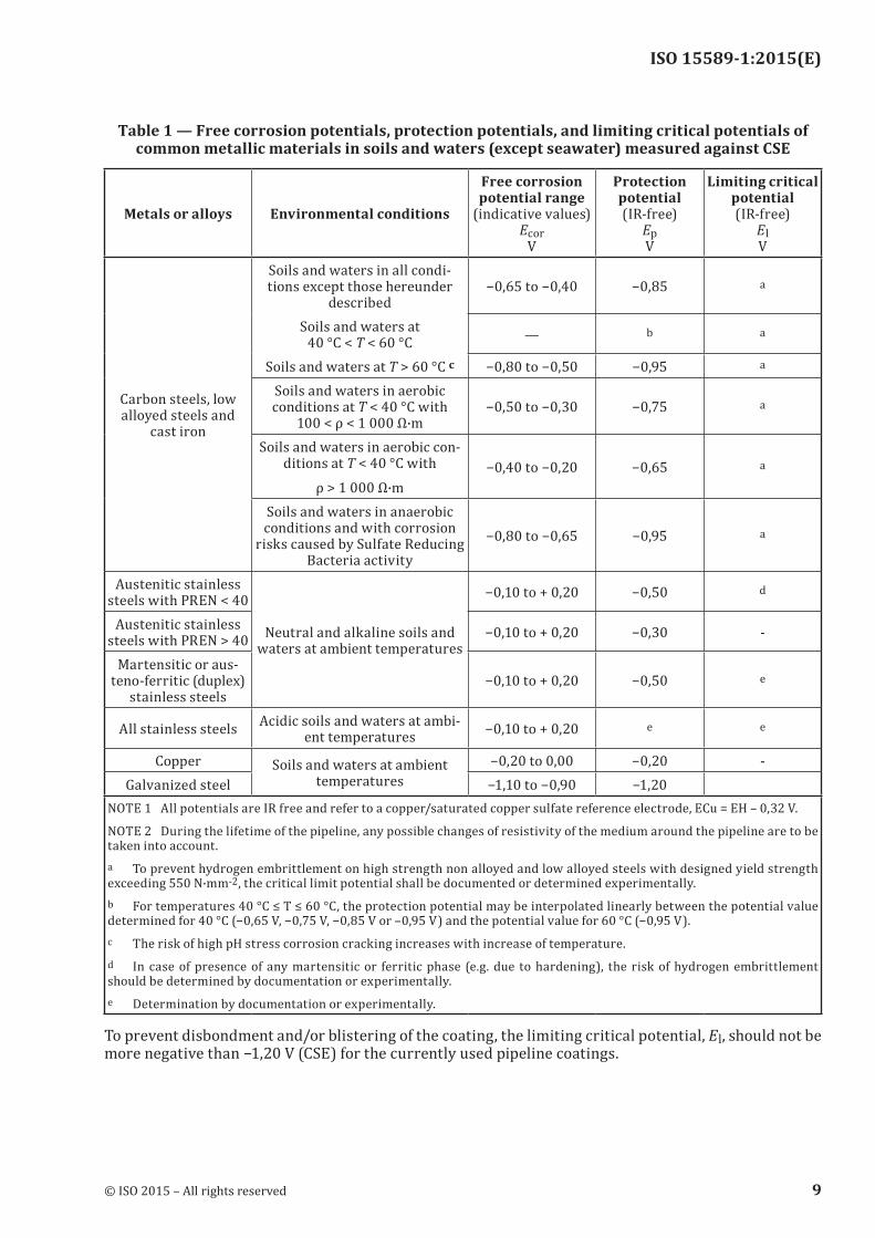

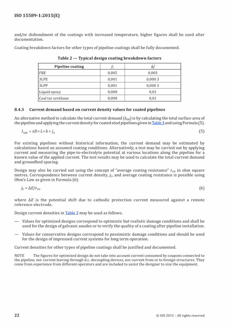
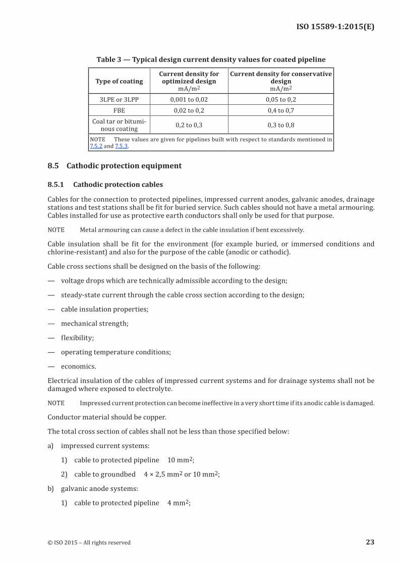

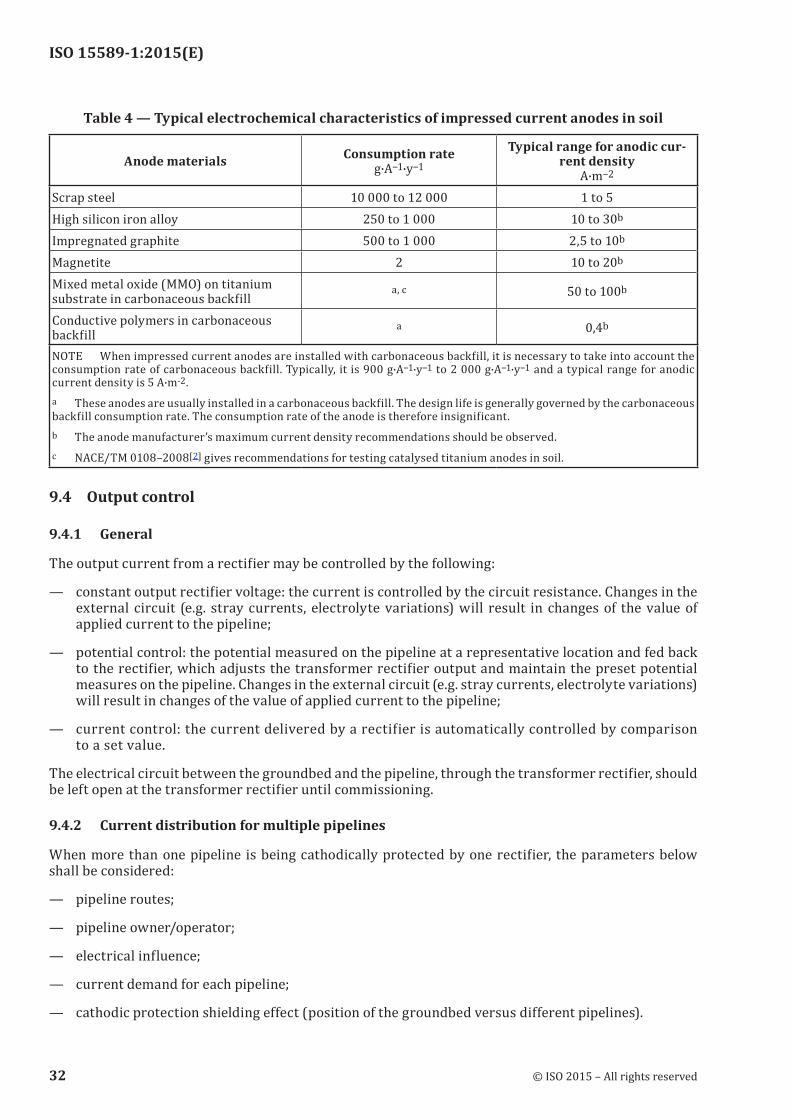
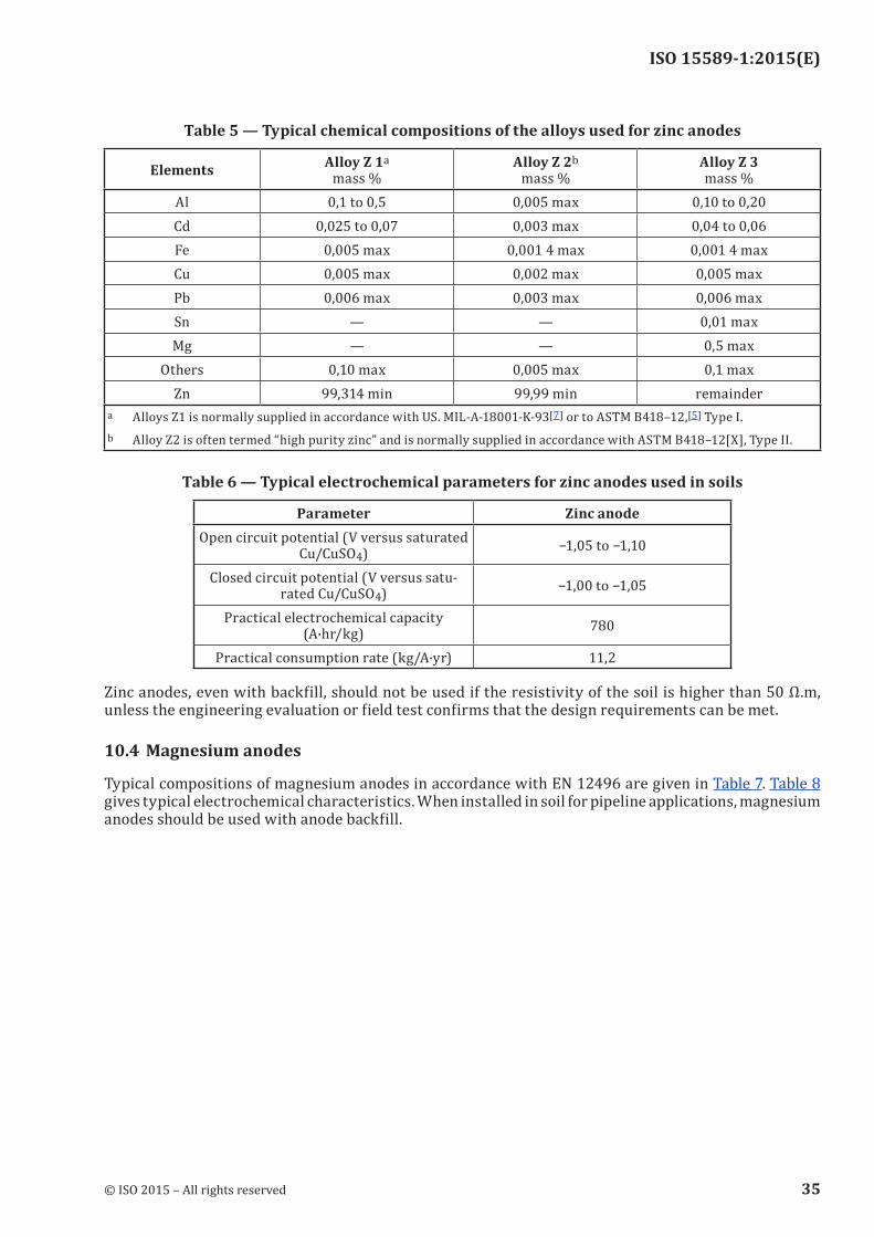
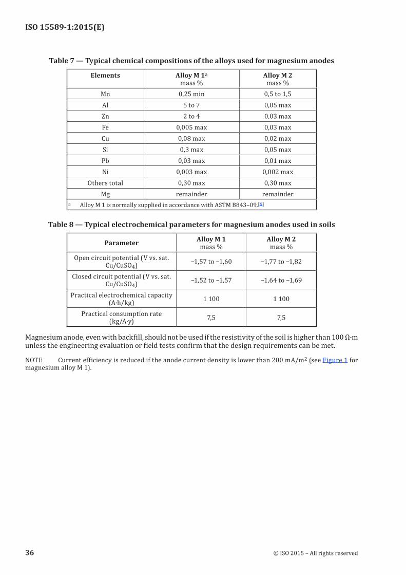
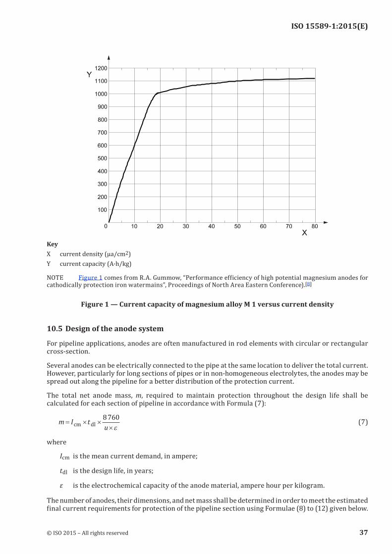


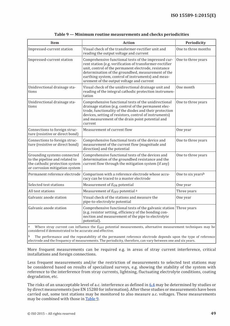


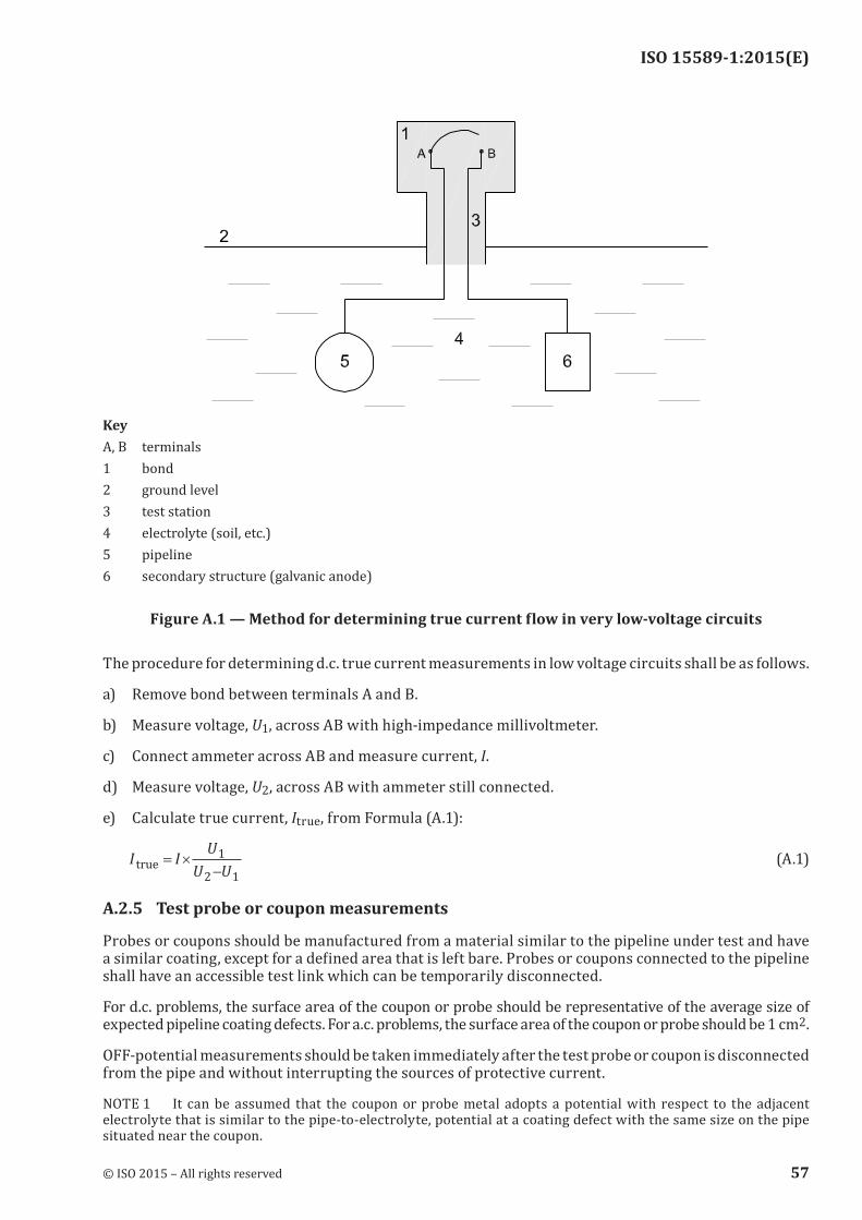
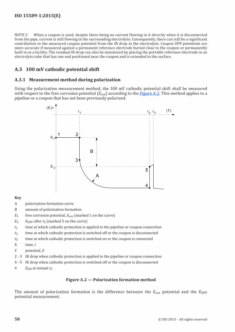
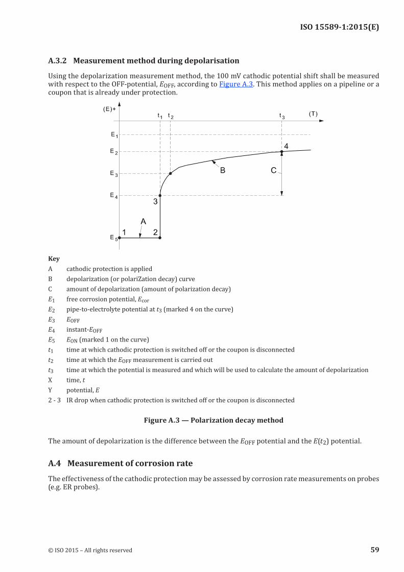
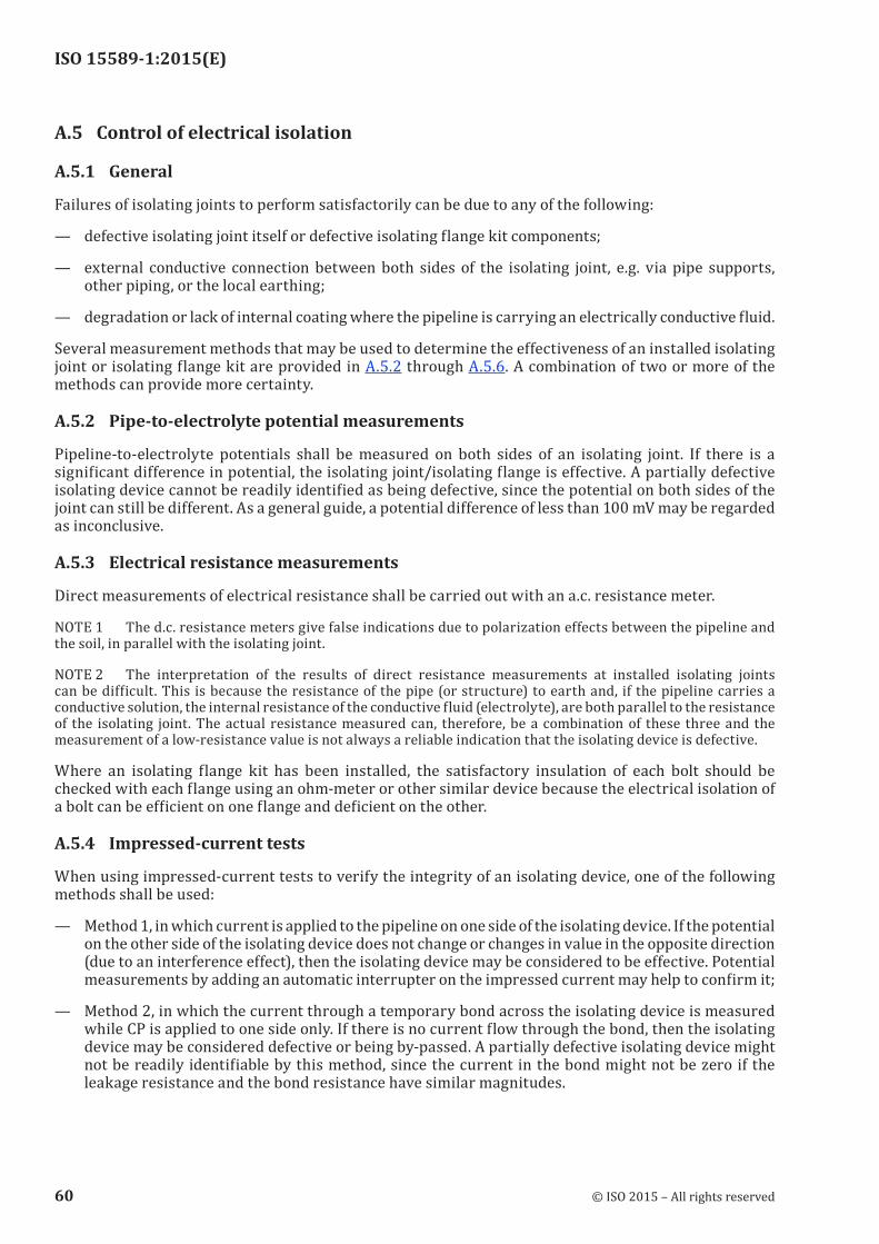
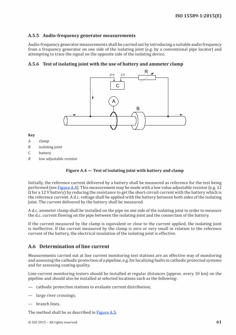
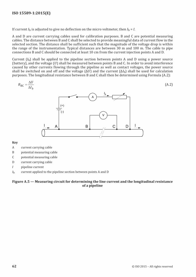

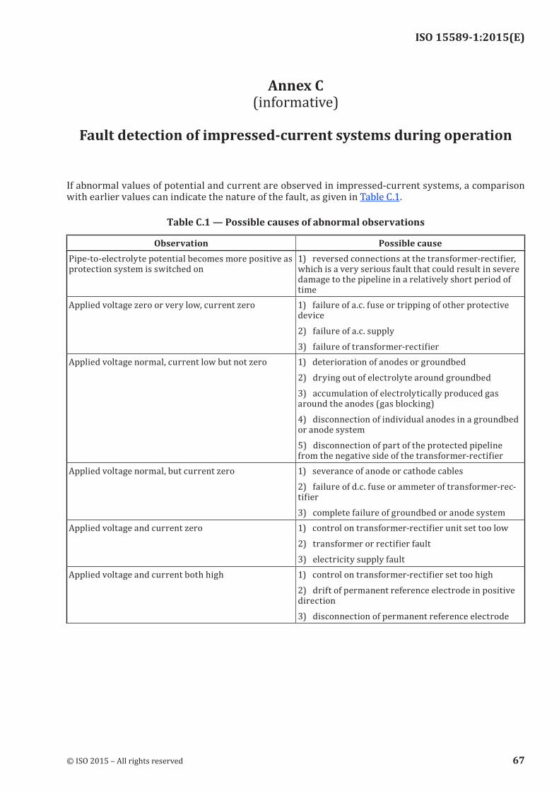
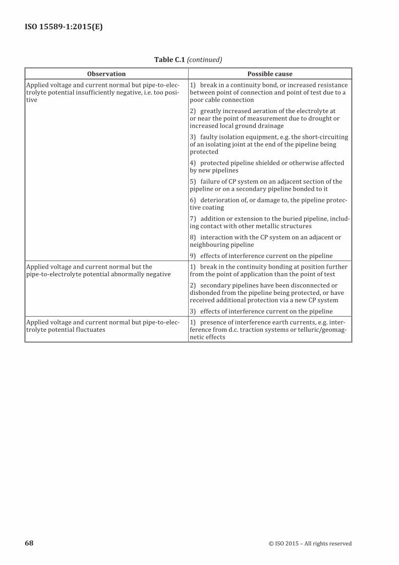
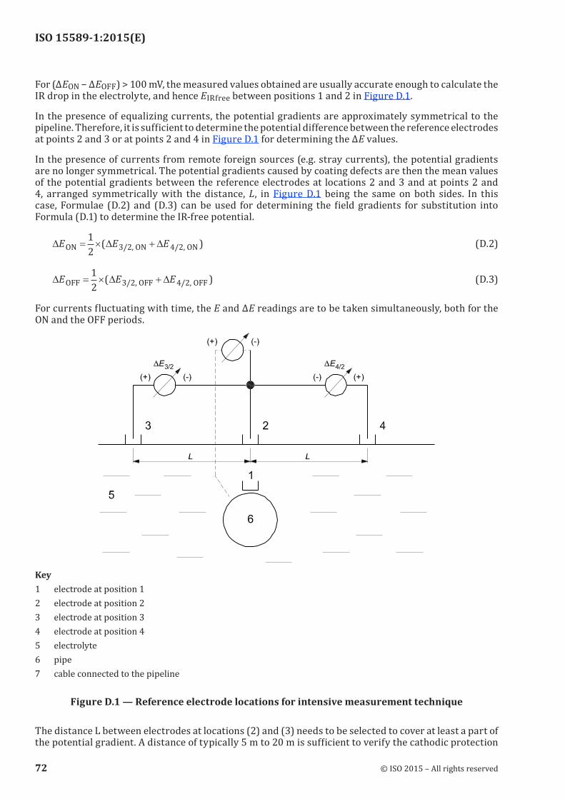
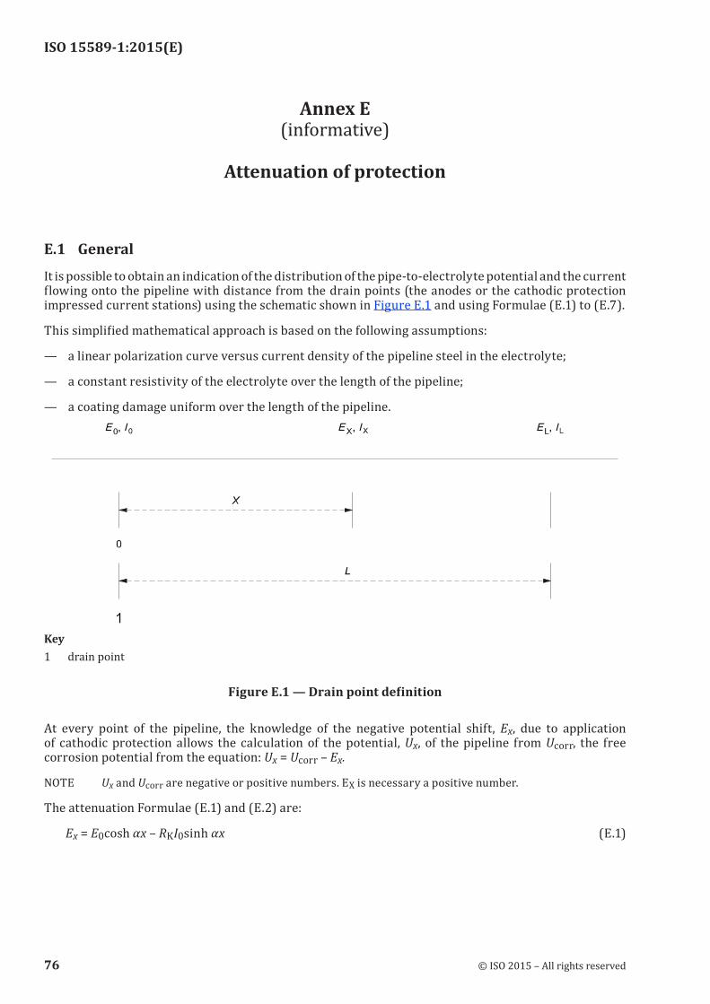

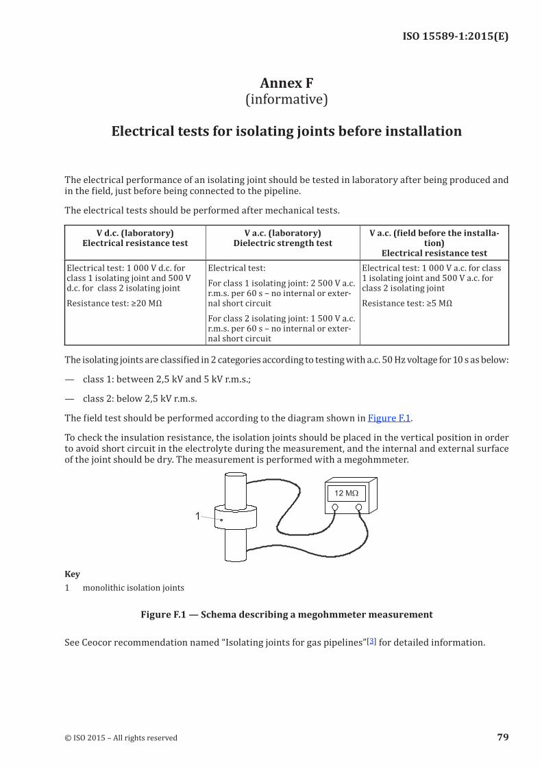

![Petroleum, petrochemical and natural gas industries ...dl.mpedia.ir/e-books/21-[ISO]ISO 14224-reliability-and-maintenance-data... · ISO 14224:2016(E) Foreword ISO (the International](https://static.documents.pub/doc/80x56/5e04f0b55f377724883ea05f/petroleum-petrochemical-and-natural-gas-industries-dl-isoiso-14224-reliability-and-maintenance-data.jpg)


