34
PEXa PLUMBING DESIGN AND INSTALLATION GUIDE RAUPEX ® UV Shield Pipe and EVERLOC+ ™ Compression-sleeve Fittings

PEXa PLUMBING DESIGN AND INSTALLATION GUIDERAUPEX® UV Shield Pipe and EVERLOC+™ Compression-sleeve Fittings
1. Scope 3
2. System Overview 4 2.1 Application 4 2.2StandardsandCertifications 4 2.3Specification 5 2.4Warranty 5 2.5DesignServices 5
3. RAUPEX PEXa Pipe 6 3.1 Pipe Properties 6 3.2PipeDimensionsandWeights 6 3.3PipeMarkings 7 3.4PressureandTemperatureRatings 7 3.5ExcessiveTemperatureandPressureCapability 7 3.6CorrosionResistance 8 3.7ChlorineResistance 8 3.8UltravioletResistance 8 3.9BendRadius 9 3.10ChemicalCompatibility 9 3.11FreezeBreakResistance 9 3.12 Condensation 9 3.13 Pressure Loss 9
4. EVERLOC+ Compression-sleeve Fittings 10 4.1FittingScope 10 4.2FittingAssembly 12 4.3 Installation Considerations 12 4.4EVERLOC+Compression-sleeveTools 15
CONTENTS
Forupdatestothispublicationandthemostcurrenttechnicalinstructions,safetyinformationandmanufacturer’srecommendations,visitwww.na.rehau.com/resourcecenter
5. Design Considerations 17 5.1PipeSizing 17 5.2EquivalentLengthofFittings 18 5.3PipingLayouts 19 5.4ThermalExpansionandContraction 20 5.5InstallationinFire-ratedAssemblies 21 5.6OverheadInstallations 23 5.7WaterQuality 24 5.8HotWaterRecirculation 25 5.9WaterHammer 25
6. Installation Considerations 26 6.1LocalCodeApprovals 26 6.2Packaging,Transport,HandlingandStorage 26 6.3UncoilingPipe 26 6.4BendingPipe 26 6.5DistanceBetweenFittings 27 6.6PipeProtection 27 6.7Insulation 28 6.9FixtureConnectionCommonComponents 28 6.10WaterHeaterConnections 29 6.11SupportingRAUPEXPipe 29 6.12SupportingEVERLOC+Fittings 30 6.13CopperSoldering 30 6.14KinkRepair 31 6.15ThawingFrozenPipe 31 6.16Disinfection 31 6.17PressureTesting 32
2

This technical information applies to the REHAU PEXa plumbing system and specifically the assembly and use of the EVERLOC+™ compression-sleeve system with RAUPEX® UV shield pipe (PEXa pipe) intended for use in hot- and cold-water potable distribution systems.
Forprofessionaluseonly.Personsusingthisguidemustbeexperi-encedandappropriatelylicensedcontractors,whohaveanunder-standingoftheprinciplesandpracticesfortheinstallationofhot-andcold-waterpotabledistributionsystems.
TheinformationpresentedinthisguideisintendedtodemonstratetheproperassemblymethodandinstallationrecommendationsfortheREHAUPEXaplumbingsystem.Itistheresponsibilityofthelicensedcontractortochecktheprevailinglocalcodesandtoverifythattechnicalinformationpresentedinthisguideisappropriateforaparticular installation.
Nothinginthisguidesupersedesnationalorlocalcoderequirementsortherecommendationsofothermanufacturersregardingtheircomponents.Observeallapplicablenational,stateandlocallaws,regulations,standards,codesandordinances.IfyoubelieveREHAUproductinformationconflictswithapplicablecoderequirements,industrystandards,ortherecommendationsofothermanufacturersregardingtheircomponents,contacttheREHAUdistributorinyourareaandconsultwiththebuildingauthorityhavingjurisdictionbeforeinstallingtheREHAUPEXaplumbingsystem.
Beforestartingtheinstallationprocess,readtheREHAUPEXa Limited Warranty,availableatwww.na.rehau.com/warranties.ItcanalsobeobtainedfromyourauthorizedREHAUdistributororbywritingtoREHAUConstructionLLC,1501EdwardsFerryRoadNE,LeesburgVA20176US.
Properinstallationistheresponsibilityoftheinstallingcontractor.ReviewtheREHAUTechnical GuidelinespriortoinstallationoftheREHAUPEXaplumbingsystem.REHAUTechnical Guidelines are definedintheREHAUPEXa Limited Warranty as:ThemostcurrentandapplicableversionsofallthetechnicalliteratureavailableontheREHAUNorthAmericawebsiteatwww.na.rehau.com/resourcecenter,including,butnotlimitedto,technicalmanuals,instructionguides,technicalbulletins,submittalsandREHAUAcademytrainingpresenta-tions.ChecktheREHAUResourceCenter(www.na.rehau.com/resourcecenter)forthelatestupdates.
ContacttheREHAUdistributorinyourareaifyoudonotunderstandtheinformationinthismanualorifyouhavequestionsabouttheREHAUTechnical Guidelines.
Thisguidecontainssafety-relatedinformationthatrequiresyourspecialattention.Itisindicatedwiththesafetyalertsymbolandthesignalwordsdescribedbelow:
DANGERIndicatesahazardoussituationwhich,ifnotavoided,willresultindeathorseriousinjury.
WARNINGIndicatesahazardoussituationwhich,ifnotavoided,couldresultindeathorseriousinjury.
CAUTIONIndicatesahazardoussituationwhich,ifnotavoided,couldresultinminorormoderateinjury.
NOTICE Indicatesariskofpropertydamage.
Onlytrainedpersonnelshouldbeengagedintheinstallationprocess.FollowtheinstructionsinthisguideandotherREHAUTechnical Guidelinesandusecommonsensetoreducetheriskofinjuryorpropertydamage.
WARNINGReadtheinstructionmanualfortheEVERLOC+compression-sleevetoolsbeforeuseandfollowallsafetyprecautions-improperusecancauseseriouspersonalinjury
WARNINGEVERLOC+compression-sleevetoolsuseastronghydraulicforcetoexpandPEXapipeandcompresscomponentsoftheREHAUEVERLOC+compression-sleevesystem.
Toreducetheriskofcrushandlacerationinjury,keepfingers,handsandallpartsofyourbodyawayfromtheexpanderhead,hydraulicslideandcompressionjawsduringoperation.Removethebatterybeforeattemptingtochangeoradjusttheexpanderheadorcompressionjaws.
EVERLOC®isaregisteredtrademarkofREHAU.DEWALT® andtheDEWALTlogoaretrademarksofStanleyBlack&Decker,Inc.,oranaffiliatethereofandareusedunderlicense.MAKITA®isatrademarkofMakitaCorporation,oranaffiliatethereof.
1. SCOPE
3
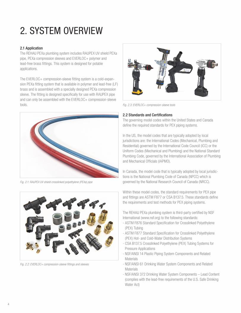
2.1 ApplicationTheREHAUPEXaplumbingsystemincludesRAUPEXUVshieldPEXapipe,PEXacompressionsleevesandEVERLOC+polymerandlead-freebrassfittings.Thissystemisdesignedforpotableapplications.
TheEVERLOC+compression-sleevefittingsystemisacold-expan-sionPEXafittingsystemthatisavailableinpolymerandlead-free(LF)brassandisassembledwithaspeciallydesignedPEXacompressionsleeve.ThefittingisdesignedspecificallyforusewithRAUPEXpipeandcanonlybeassembledwiththeEVERLOC+compression-sleevetools.
Fig. 2.1: RAUPEX UV shield crosslinked polyethylene (PEXa) pipe
Fig. 2.2: EVERLOC+ compression-sleeve fittings and sleeves
2. SYSTEM OVERVIEW
Fig. 2.3: EVERLOC+ compression-sleeve tools
2.2 Standards and CertificationsThegoverningmodelcodeswithintheUnitedStatesandCanadadefinetherequiredstandardsforPEXpipingsystems.
IntheUS,themodelcodesthataretypicallyadoptedbylocaljurisdictionsare:theInternationalCodes(Mechanical,PlumbingandResidential)governedbytheInternationalCodeCouncil(ICC)ortheUniformCodes(MechanicalandPlumbing)andtheNationalStandardPlumbingCode,governedbytheInternationalAssociationofPlumbingandMechanicalOfficials(IAPMO).
InCanada,themodelcodethatistypicallyadoptedbylocaljurisdic-tionsistheNationalPlumbingCodeofCanada(NPCC)whichisgovernedbytheNationalResearchCouncilofCanada(NRCC).
Withinthesemodelcodes,thestandardrequirementsforPEXpipeandfittingsareASTMF877orCSAB137.5.ThesestandardsdefinetherequirementsandtestmethodsforPEXpipingsystems.
TheREHAUPEXaplumbingsystemisthird-partycertifiedbyNSFInternational(www.nsf.org)tothefollowingstandards:-ASTMF876StandardSpecificationforCrosslinkedPolyethylene(PEX)Tubing-ASTMF877StandardSpecificationforCrosslinkedPolyethylene(PEX)Hot-andCold-WaterDistributionSystems-CSAB137.5CrosslinkedPolyethylene(PEX)TubingSystemsfor
Pressure Applications-NSF/ANSI14PlasticPipingSystemComponentsandRelated
Materials-NSF/ANSI61DrinkingWaterSystemComponentsandRelated
Materials-NSF/ANSI372DrinkingWaterSystemComponents–LeadContent(complieswiththelead-freerequirementsoftheU.S.SafeDrinkingWater Act)
4

2.3 SpecificationREHAUprovidesarecommendedspecificationfordomesticwaterpipingandfittings.Thisrecommendedspecificationisprovidedasaguidefordevelopmentofthefinalspecificationbyaarchitect,engineer,orbuilder.Thearchitect/engineer/buildershallberespon-sibletoconvertthisrecommendedspecificationintoafinalspecifica-tionthatmeetsthefunctionalneedsoftheclient,aswellastocomplywithallapplicablebuilding,plumbing,andmechanicalcodes.Specificationsareavailableatwww.na.rehau.com/resourcecenter.
2.4 WarrantyRAUPEXUVshieldpipeandEVERLOC+compression-sleevefittingsandsleevesarebackedbya25-yearlimitedwarranty.EVERLOC+compression-sleevetoolsarebackedbya2-yearlimitedwarranty.REHAUoffersthiswarrantywhentheinstallationiscarriedoutinaccordancewiththerequirementsoutlinedintheREHAUPEXa Warranty 855.018,whichisavailableasaseparatedocumentatwww.na.rehau.com/warranties.Pleasereadwarrantypriortoinstallation.
2.5 Design ServicesREHAUDesignServicescanprovidecustomerswithadetailedsubmittalpackagetosupporttheinstallationoftheREHAUPEXaplumbingsystem.
REHAUPlumbingDesignServicesinclude: - BIMlibraryofplumbingsystemcomponents - Productsubmittals - Projectbillofmaterials - Supportofpipelayoutbasedontheprojectengineer’sapprovedplumbingpipingdesign
2.5.1 Building Information Modeling LibraryTheREHAUBIMLibraryoffersadirectoryofdrawingsthatareeasytodownloadintoanactivedesign.BIMfilesofferefficienciestoprojectownersthrougheaseofcollaboration.TheREHAUBIMlibraryoffersmodelsofcoreproductsincludingpipe,fittings,manifoldsandinstallation accessories.
2.5.2 LoopCAD® SoftwareREHAUPlumbingCADcreatesprofessionalpipelayoutdrawingsandbillofmaterialsfortheREHAUPEXaplumbingsystem.
5
3. RAUPEX PEXa PIPE
3.1 Pipe PropertiesCrosslinkedpolyethyleneispolyethylene(PE)whichhasundergoneachangeinmolecularstructurewherebythepolymerchainsarechemicallylinked,crosslinked(X),witheachothertoformathree-dimensionalnetwork.Theresultisaflexiblethermosetpolymerwithimprovedmechanical,thermalandchemicalproperties.
TherearethreemethodsofmanufacturingPEX:-Theperoxidemethod(PEXa),ASTMrequiresaminimumof70%crosslinkedPEmolecules-Thesilanemethod(PEXb),ASTMrequiresaminimumof65%crosslinkedPEmolecules-Theradiationmethod(PEXc),ASTMrequiresaminimumof65%crosslinkedPEmolecules
RAUPEXpipeismanufacturedusingtheperoxidemethod(PEXa),whichyieldsthehighest,mostconsistentlevelofcrosslinking.PEXatechnologyenhancesflexibilityandthermalmemory,providingeaseofhandlingandkinkrepaircomparedtoPEXbandPEXc.
PEXahasdistinctadvantagesovermetalandotherpolymerpipes:-Resistspittingandstresscorrosion-Resistsscalinganddepositbuild-upwhenusedwithbothhardandsoftenedwater-Minimizesnoisethatistransmittedthroughpipes-Resistsnotchingandabrasiondamage
RAUPEXismanufacturedbyREHAUinafacilitywhosequalitymanagementsystemisISO9001certified.Inaddition,RAUPEXproductionisindependentlymonitoredannuallyNSFInternational,CSAInternationalandUnderwritersLaboratoriesInc.(UL).
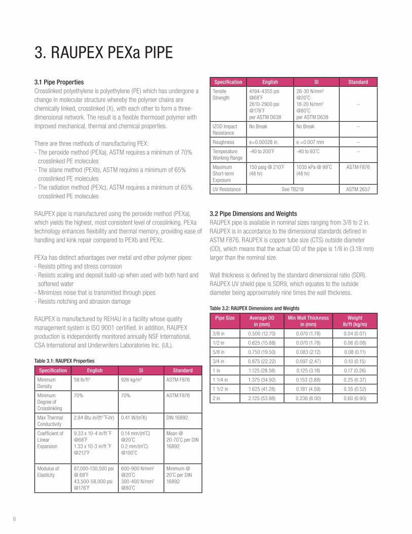
Table 3.1: RAUPEX Properties
Specification English SI Standard
MinimumDensity
58lb/ft3 926kg/m3 ASTMF876
MinimumDegreeofCrosslinkling
70% 70% ASTMF876
MaxThermalConductivity
2.84Btuin/(ft2 ˚F•hr) 0.41W/(m˚K) DIN16892
CoefficientofLinear Expansion
9.33x10⁻⁴in/ft˚F@68˚F1.33x10-3in/ft˚F@212˚F
0.14mm/(m˚C)@20˚C0.2mm/(m˚C)@100˚C
Mean @ 20-70˚CperDIN16892
ModulusofElasticity
87,000-130,500psi@68˚F43,500-58,000psi@176˚F
600-900N/mm2 @20˚C300-400N/mm2 @80˚C
Minimum@20˚CperDIN16892
Specification English SI Standard
Tensile Strength
4194-4355psi@68˚F2610-2900psi@176˚FperASTMD638
26-30N/mm2 @20˚C18-20N/mm2 @80˚CperASTMD638
--
IZODImpactResistance
No Break No Break --
Roughness e=0.00028in. e=0.007mm --
TemperatureWorkingRange
-40to200˚F -40to93˚C --
MaximumShort-termExposure
150psig@210˚F(48hr)
1035kPa@99˚C(48hr)
ASTMF876
UVResistance SeeTB218 ASTM2657
3.2 Pipe Dimensions and WeightsRAUPEXpipeisavailableinnominalsizesrangingfrom3/8to2in.RAUPEXisinaccordancetothedimensionalstandardsdefinedinASTMF876.RAUPEXiscoppertubesize(CTS)outsidediameter(OD),whichmeansthattheactualODofthepipeis1/8in(3.18mm)largerthanthenominalsize.
Wallthicknessisdefinedbythestandarddimensionalratio(SDR).RAUPEXUVshieldpipeisSDR9,whichequatestotheoutsidediameterbeingapproximatelyninetimesthewallthickness.
Table 3.2: RAUPEX Dimensions and Weights
Pipe Size Average OD in (mm)
Min Wall Thicknessin (mm)
Weightlb/ft (kg/m)
3/8in 0.500(12.70) 0.070(1.78) 0.04(0.07)
1/2in 0.625(15.88) 0.070(1.78) 0.06(0.08)
5/8in 0.750(19.50) 0.083(2.12) 0.08(0.11)
3/4in 0.875(22.22) 0.097(2.47) 0.10(0.15)
1 in 1.125(28.58) 0.125(3.18) 0.17(0.26)
11/4in 1.375(34.92) 0.153(3.88) 0.25(0.37)
11/2in 1.625(41.28) 0.181(4.59) 0.35(0.52)
2 in 2.125(53.98) 0.236(6.00) 0.60(0.90)
6

3.3 Pipe MarkingsRAUPEXpipemarkingsarerepeatedevery3ft(0.9m),listallcertificationsandapprovals,andincludeanincrementalfootagemarkingtoassistwithinstallation.
3.3.1 PEX Designation CodeRAUPEXpipeisfurtheridentifiedwithaPEXMaterialDesignationcodeinaccordancetoASTMF876.ThePEXDesignationCodeistheabbreviationforthematerial-PEX-followedbyfournumerals.
The PEX Designation Code for RAUPEX UV shield pipe is
PEX 3306
Thefirstnumeral(3)referstothechlorineresistanceinoneoffourcategories,whentestedinaccordancewithASTMTestMethodF2023andevaluatedinaccordancewithASTMF876.Thismeasurementindicatestheallowablehoursof140°Fwaterrecirculationin1day.
0 = none1 = 4 hours
e.g., 25% of lifetime
3 = 12 hourse.g., 50% of lifetime
5 = 24 hourse.g., 100% of lifetime
Thesecondnumeral(3)referstoUVresistanceinoneoffourcategories,whentestedinaccordancewithASTMTestMethodF2657andevaluatedinaccordancewithASTMF876.ThemeasurementindicatestheallowabletimepipecanbeexposedtoUVwithoutbeingcompromised.
0 = none 1 = 1 month 2 = 3 months 3 = 6 months
Thethirdandfourthnumerals(06)refertotheHydrostaticDesignStressforwaterat73°Finhundredsofpsi.Thestandardpressureratingat73°Fisderivedfromthismeasurement.
06 = 630 psi
3.4 Pressure and Temperature RatingsThemaximumtemperatureandpressureratingsoftheRAUPEXplumbingsystemareinaccordancetoASTMF876,CSAB137.5andPPITR-3.Thedesignershalldeterminetheactualconditionsandapplytheappropriateandadditionaldesignfactorsasrequiredforanyparticularproject.
AccordingtotheREHAUPEXa Limited Warranty,theRAUPEXpipewarrantyperiodisforoperatingconditionsatorbelow180°F(82.2°C)inpermittedapplicationswhenthehandling,use,installationandmaintenancecontinuallycomplieswithallREHAUTechnical Guidelines.
Table 3.3: RAUPEX UV Shield Pipe Pressure and Temperature Ratings
RAUPEX UV shield Pipe
Maximum Pressures and Temperatures Design Factors
[email protected]°F(1055kPa@23°C) 0.50(perASTMF876,CSAB137.5)
100psi@180°F([email protected]°C) 0.50(perASTMF876,CSAB137.5)
80psi@200°F([email protected]°C) 0.50(perASTMF876,CSAB137.5)
REHAUdefinesElevated Temperature Applicationsasthosewithoperatingconditionsgreaterthan180°F(82.2°C).WhenRAUPEXpipesareplannedtobeoperatedinconditionsgreaterthan180˚F(82.2°C),thedesignermustsufficientlyconsiderthethermalandoxidativestabilityperformanceofthepipingmaterialtoensurethePEXapipedesignwillmeetprojectserviceliferequirements.
For Elevated Temperature Applications,REHAUadvisesagainsttheuseofastressreductiondesignfactorthatlowerstheoperatingpressureasitmaynotsufficientlyaccountforthermaloroxidativedegradation.
REHAUappliesaservicelifemethodologyforRAUPEXpipesdrawnfromASTMF876,CSAB137.5,ISO9080andMiner'sruleaccordingtoDIN13760todeterminethewarrantyperiod.RAUPEXpipesshouldalwaysbeoperatedatorbelowtheREHAUpublishedtemperatureandpressureratings.
Whentheoperatingconditionsarelessthanorequalto180°F(82.2°C),thenaccordingtotheREHAU PEXa Limited Warranty thewarrantyperiodforRAUPEXpipeis25years.WhenRAUPEXpipesare operated in Elevated Temperature Applications,wheretheoperatingconditionsaregreaterthan180°F(82.2°C),contactREHAUEngineeringtoverifyyouroperatingconditionscomplywiththerequirementsintheREHAU PEXa Limited Warrantyforawarrantyperiodof25years.
3.5 Excessive Temperature and Pressure CapabilityTemperatureandpressure(T&P)reliefvalvesaresafetymechanismsincasethesystemoverheats(mandatoryinhotwaterdistributionsystems).Thesevalvesactquicklytorelieveexcesstemperatureorpressureifeitheroneoftheseconditionsisreached.IntheeventofawaterheatingsystemfailureorT&Preliefvalvefailure,RAUPEXpipehasbeentestedtoaccommodateshort-termexposureconditionsof210°F(99°C)at150psi(10bar)for48hours.
NOTICEFailuretofollowpressureandtemperaturelimitsmaydamagethepiperesultinginleaksandoperationalfailures,andwillnegateanywarrantyprovidedbyREHAUforRAUPEXpipes.Thedesignermustincorporatepropercontrolsintothesystemtoensurethepressureandtemperaturecapabilityofthepipeisnotexceeded.
7

3.6 Corrosion ResistanceRAUPEXpipeisnon-reactiveanddisplaysexcellentcorrosionresistance.Corrosionisaprocessthatrequireselectricallyconductivematerialsandoccursonmetals.PEXa,beingadielectric,doesnotcorrodelikemetalpipes.PEXaalsoresiststhebuildupofscalewhichiscommonwithcopperpipe.
3.7 Chlorine ResistanceRAUPEXpipehasbeentestedinaccordancewithASTMF2023,Standard Test Method for Evaluating the Oxidative Resistance of Crosslinked Polyethylene (PEX) Tubing and Systems to Hot Chlorinated Water asrequiredinASTMF876.RAUPEXpipeexceedstheminimumextrapolatedtestlifetimeascertifiedbyNSFandPPIforcoldwaterapplications,intermittenthotwaterapplicationsandtimedhotwaterapplications.
Basedonthistesting,whenusingRAUPEXUVshieldpipeforplumbingapplicationswithoutcontinuoushotwaterrecirculation,thefollowingwaterqualityconditionsmustbemet:-ThepHofwateris7.0orhigher-Theconcentrationoffreechlorineis4.0ppmorlower-Watertemperatureis140°F(60°C)orlower-Waterpressureis80psig(550kPa)orlower-Oxidativereductionpotential(ORP)of825mVorlower
ThisrecommendationappliestoRAUPEXUVshieldplumbingpipesforcoldwaterandintermittenthotwaterapplications(25%@140°F,75%@73°F)andfortimedhotwaterrecirculationsystemsforupto12hoursperday(50%@140°F,50%@73°F).TheASTMF876standardincludesdesignationcodesfortheseapplicationswhichareincludedontheprintlineofRAUPEXpipes.
WhenusingRAUPEXUVshieldpipeforplumbingapplicationswithcontinuoushotwaterrecirculation,thefollowingwaterqualityconditionsmustbemet:-ThepHofthewateris7.9orhigher-Theconcentrationoffreechlorineis2.4ppmorlower-Watertemperatureis140°F(60°C)orlower-Waterpressureis80psig(550kPa)orlower-Oxidativereductionpotential(ORP)of750mVorlower
Iftheseconditionsarenotmet,itisnecessarytoincorporateatimecontrolsothesystemoperatesatamaximum50%@140°Fand50%@73°F.
Itshouldalsobenotedthatinrareandisolatedcases,othercharac-teristicsofthemakeupofdrinkingwatercanimpactthelong-termperformanceofplumbingsystemcomponentsevenwhenthewaterqualitylevelsarewithinthepermissiblerangesetforthbythe
EPANational Primary Drinking Water RegulationsandtheGuidelines for Canadian Drinking Water QualitybyHealthCanada.Thelicensedinstallingcontractormusthavepracticalexperiencewithintheregionofintendeduse.Inaddition,consultationwiththelocalplumbingauthorityandlocalwaterauthorityregardingtheperformanceofplumbingsystemcomponentsshouldoccurbeforetheselectionandinstallationofsystemswithinthatspecificgeographicregion.Therefore,thespecificapplicationshouldalsobetakenintoconsider-ationwhendesigningandinstallingplumbingsystems.
3.8 Ultraviolet ResistanceAllpolymersaresusceptibletodamagefromexposuretotheultraviolet(UV)radiationinsunlight.PEXpipescanbedesignedtoprotectagainstshort-termUVdamage,butaftersometime,UVradiationwillreducethelifetimeofthepipe.Theextentofthereductiondependsonfactorssuchastemperature,pressureandchlorinationlevelsinpotablewater.
REHAUhasperformedextensivetestingofRAUPEXpipesexposedtonaturalsunlight,leadingtothemaximumUVexposuretimesex-pressedinaccumulateddays.Oncethepipesleavethemanufacturingplant,anyexposuretoUV,includingtransportationandstoragebythewholesaler,ispartoftheaccumulatedexposuretime.
AlthoughASTMF876onlycategorizesupto6monthsofUVresis-tance(MaterialDesignationCode=3306),REHAUhastestedandcertifiedRAUPEXUVshieldpipeaccordingtoASTMF2657forthefollowingmaximumUVexposureperiod:
-RAUPEXred,whiteandblueUVshieldpipe:Maximumexposuretimeofoneyearaccumulated
RAUPEXpipesmustbekeptintheoriginalpackaginguntilthetimeofinstallation.RAUPEXmustnotbestoredoutdoorsandisnotdesignedforpermanentoutdoorexposure(withtheexceptionofnon-exposedburiedapplications).ExcessiveUVexposurewillreducethelifetimeofPEXapipe.
3.8.1 UV Emitted by Fluorescent LampsASTMF2657wasestablishedtotesttotheworstcasescenarioforUVexposurebytestingindirectsunlight.UVemittedbyfluorescentlampsisinsignificantwhencomparedtoUVpresentinsunlight.GELightinghasstated“SolarUVisenormouslymorephotoactiveanddamagingthantheUVfromlinearfluorescentlamps.SolarUVincludesUV-A,UV-BandUV-C.UV-AisnearUV,notveryenergeticandisthebulkofUVemittedbyflorescentlamps.”Therefore,when
8

REHAUPEXapipesareinstalledinthepresenceoffluorescentlampstheUVemittedbythoselampsshouldhavenoeffectonthelifetimeofthepipes.Forexample,thereisnoconcernofUVdamageonREHAUPEXapipesinstalledinaboilerroomwherefluorescentlampsarepresent.
NOTICEFailuretofollowmaximumUVexposurelimitsmaydamagethepiperesultinginleaksandoperationalfailures,andwillnegateanywarrantyprovidedbyREHAUforRAUPEXpipes.
3.9 Bend RadiusRAUPEXpipemaybebent,evenwhencold.REHAUsupportbendscanassisttocreatetightbendswithoutkinking.Thetypicalbendradiususedbytheinstalleris8XtheOD.Theminimumbendradiusis5XtheODforcoldbends.Foranevensmallerbendradius,thepipemaybeheatedwithaheatgunandbenttonolessthan3XtheOD.Ifatighterbendradiusisrequired,thenthedesignershouldconsiderusingasmallerdiameterpipe.
Table 3.4: RAUPEX Bend Radius
Bend Radius in (mm)
Pipe Size Typical 8X OD Min. Cold 5X OD Min. Heated 3X OD
3/8in 4.0(102) 2.500(64) 1.500(38)
1/2in 5.0(127) 3.125(79) 1.875(48)
5/8in 6.0(152) 3.750(95) 2.250(57)
3/4in 7.0(178) 4.375(111) 2.625(67)
1 in 9.0(229) 5.625(143) 3.375(86)
11/4in 11.0(279) 6.875(175) 4.125(105)
11/2in 13.0(330) -- --
2 in 17.0(432) -- --
3.10 Chemical CompatibilityWhileRAUPEXpipesareresistanttomanychemicalsthatareusedintypicalplumbingapplications,therearesomechemicalsthatmaydamagethepipe.
Chemicalsthatmaybedamaginginclude(butarenotlimitedto):-Adhesives-Oilorpetroleum-basedproducts-Paints-Solvents-Oxidizingagents-Disinfectants-PVCglues-Solventsandcements
Manyfactors,suchasexposuretime,temperature,pressureandotheroperatingparameters,caninfluencetheperformanceofapipethatisexposedtoachemical.Todeterminetheimpactofaparticularchemical,short-andlong-termpressuretestingmayberequired.Insomecases,apipemayberesistanttoshort-termexposuretothechemical,butnotresistanttocontinuousexposure.Eachchemicalmustbeevaluatedindividually.Itistheresponsibilityoftheinstallingcontractortoverifychemicalcompatibilityofanychemicalswhencomingintocontactwiththepolymermaterial.
3.11 Freeze Break ResistanceTheflexibilityoftheRAUPEXpipeallowsittoexpandaswaterfreezesinthepipeaslongasthepipehasroomtoexpand.Whenthewaterthaws,thepipereturnstoitsoriginalshape.Ifthepipeisnotallowedtoexpand(e.g.,itisencasedinconcrete),itmayburst.
NOTICEDesignersandinstallersmusttakeprecautionstoensurethatpipesdonotfreeze.Frozenpipesmayburstresultinginleaksandoperationalfailures.
3.12 CondensationCondensationoccursonpipeswhenthesurfacetemperatureislowerthanthedewpointoftheenvironment.Thisistypicallyaproblemformetalliccoldwaterpiping.PEXpipehasalowerthermalconductivity(0.41W/m°K)thancopper(401W/m°K)resultinginlessheatlosstothesurfaceandgreaterresistancetocondensationorsweating.Insulationshouldbeappliedtopipingtohelppreventcondensation.
3.13 Pressure LossThepressurelossinthePEXasystemdependsontheflowrate,watertemperaturesandthepropertiesofthefluid.UsetheREHAULoopCAD®Softwarewhichincludesabuilt-incalculatortodeterminepipepressurelossesforthegivenconditions.RefertotheREHAU PEXa Piping Systems Pressure Loss Tablesfortheapplicablepressurelosstablepresentedattypicalflowratesandwatertemperatures.ThepressurelossinPEXacarrierpipeisbasedontheapplicationoftheD’Arcy-WeisbachequationandfluidpropertiesfromASHRAEFundamentals.
9

4. EVERLOC+ COMPRESSION-SLEEVE FITTINGS
4.1 Fitting Scope TheEVERLOC+compression-sleevesystemisacold-expansionPEXafittingsystemthatisavailableinpolymerandlead-free(LF)brassandisassembledwithaspeciallydesignedPEXacompressionsleeve.ThefittingisdesignedspecificallyforusewithRAUPEXpipeandmustonlybeassembledwiththeEVERLOC+compression-sleevetools.
EVERLOC+fittingsareavailablein3/8,1/2,5/8,3/4,1,11/4,11/2and2in.sizesandareintendedforusewithRAUPEXSDR9coppertubesize(CTS)pipemanufacturedinaccordancewithASTMF876
ForadetaileddescriptionoftheREHAUsystemcomponents,refertotheREHAUSustainable Building Technology Product Catalog (855.312).
4.1.1 Fitting FeaturesEVERLOC+polymerandlead-free(LF)brassfittingshavethefollowingfeatures:1. Foursealingedges2. Pipe stop3. Fittingcollar4. Tooljawbody
Fig. 4.1: EVERLOC+ fitting features
4.1.2 Fitting and Sleeve MarkingsAllpolymerfittingsincludethefollowingmarksforidentification
OR
Fig. 4.2: Fitting size marking (e.g., 3/4”)
Fig. 4.3: Batch code (e.g., production date)
AllLFbrassfittingsaremarked"REHAU"
Allsleevesincludethefollowingmarksforidentification
-Sleevesize(e.g.,1/2")-Batchcodeforproductiondate
Fig. 4.4: Sleeve markings
1
2
4
3
10

4.1.3 Polymer FittingsEVERLOC+polymerfittingsareavailableincouplings,tees,elbows,multi-portteesandplugs.Allpolymerfittingsareproducedfromapolyphenylsulfone(PPSU)materialthatmeetstherequirementsofNSF61forhealtheffectsofdrinkingwatersystemcomponentsandcomplieswiththelead-freerequirementsoftheU.S.SafeDrinkingWaterAct.SeealsoREHAUTechnical Bulletin TB265 EVERLOC+ Polymer Fitting Material - PPSU.
Fig. 4.5: EVERLOC+ polymer fittings
4.1.4 Lead Free (LF) Brass FittingsEVERLOC+LFbrassfittingsareavailableascouplings,tees,elbows,plugsandtransitionfittingstoNPTthreadandcoppersolderconnections.AllmetalfittingsareproducedfromECOBRASS®(UNS69300orCW724R)thatmeetstherequirementsofNSF61forhealtheffectsofdrinkingwatersystemcomponentsandcomplieswiththelead-freerequirementsoftheU.S.SafeDrinkingWaterAct.SeealsoREHAUTechnical Bulletin TB264 EVERLOC+ Lead-free Brass Fitting Material.
Fig. 4.6: EVERLOC+ LF brass fitting
4.1.5 Metal ManifoldsManifoldsare1in.TypeLcopperwithEVERLOC+LFbrassfittingsbrazedintotheheader.
Fig. 4.7: EVERLOC+ metal manifold
4.1.6 PEXa Compression SleevesEVERLOC+compressionsleevesareproducedusingaspeciallyformulatedPEXamaterialandaredesignedspecificallyforusewithEVERLOC+fittingsandRAUPEXpipe.EVERLOC+compressionsleeveshavethefollowingfeatures:-Co-extrudedplatinum-coloredPEcoating-Squarelycutendsthatcanbeslidoverthepipeineitherdirection-Groovedandroughenedinsidesurfaceforlockingthesleeveintoplaceonceslidoverthepipeandfitting
Fig. 4.8: EVERLOC+ compression sleeves
4.1.8 CertificationsTheEVERLOC+compression-sleevesystemiscertifiedtothefollowingstandards:-ASTMF877,Standard Specification for Crosslinked Polyethylene
(PEX) Hot- and Cold-Water Distribution Systems-NSF/ANSI14,Plastic Piping System Components and Related
Materials-NSF/ANSI61,Drinking Water System Components – Health Effects-NSF/ANSI372,Drinking Water System Components – Lead Content-CSAB137.5,Crosslinked polyethylene (PEX) Tubing Systems for
Pressure Applications
11

4.2 Fitting Assembly Beforestartingtheinstallationprocess,readtheEVERLOC+ Compression-sleeve System Product Instructions (855.724).
AssemblingtheEVERLOC+compression-sleevesystemrequirestheuseoftheEVERLOC+compression-sleevetools.OnlymakeEVERLOC+compression-sleevejointswiththesetools.RefertoEVERLOC+ Power Tool Product Instruction Manual (855.725),EVERLOC+ XL Power Tool Product Instruction Manual(855.728)andEVERLOC+ XL Expander Tool Product Instruction Manual(855.729)foracompleteunderstandingofoperation,careanduseoftheEVERLOC+compression-sleevetools.
WARNINGReadtheinstructionmanualfortheEVERLOC+compression-sleevetoolsbeforeuseandfollowallsafetyprecautions-improperusecancauseseriouspersonalinjury.
WARNINGToreducetheriskofpermanenteyeinjury,alwayswearclose-fittingprotectiveeyewearwithsideprotection.Eyewearmustbeimpact-ratedandmarkedascomplyingwithANSIZ87.
NOTICEUseonlyEVERLOC+compression-sleevetoolsforassemblyandinstallation.Useofothertoolswillresultinanimproperlyassembledjoint,whichmayresultinleakingandpropertydamage.
ThebasicprocessofassemblinganEVERLOC+compression-sleevejointisasfollows:-Makeaclean,squarecutoftheRAUPEXpipeusingaRAUPEX
cutter-SlidetheEVERLOC+compressionsleeveovertheRAUPEXpipeensuringthesleeveisaminimumoftwotimesthelengthofthesleevefromtheendofthecutpipetoallowforexpansionofthepipeonly-ExpandtheRAUPEXpipetwice,ensuringtheexpanderheadisrotated1/2ofoneexpanderheadsegmentbetweenexpansions,usingtheEVERLOC+compression-sleevetools-InserttheEVERLOC+compression-sleevefittingintotheexpandedendoftheRAUPEXpipeuntilthepipeistouchingthepipestoponthefitting-CompresstheEVERLOC+compressionsleeveovertheRAUPEXpipeandEVERLOC+compression-sleevefittingusingtheEVERLOC+compression-sleevetools
Requiredassemblytoolsinclude:-RAUPEXcutter-EVERLOC+compression-sleevetools-EVERLOC+expanderheadsandcompressionjaws
4.3 Installation Considerations Someprecautionsandadditionalconsiderationsthatshouldbetakenwheninstallingthesystem.
4.3.1 EVERLOC+ Fitting Removal -EVERLOC+LFbrassfittingsCANbereused,aslongtheribareawasnotdamagedduringremoval.-EVERLOC+polymerfittingsCANNOTbereusedandshouldbediscardedimmediately.-EVERLOC+compressionsleevesCANNOTbereusedandshouldbediscardedimmediately.
Fig. 4.9: DO NOT cut the EVERLOC+ compression sleeve from finished joint
Fig. 4.10: DO NOT cut RAUPEX pipe from fitting
4.3.1.1 Fitting Removal of Completed Joint (LF brass ONLY)IfitisrequiredtoremovetheLFbrassfittingordisassembletheLFbrasscompression-sleevejoint,usethefollowingprocedure:
Ifthefittinghasbeeninsertedintothepipeandthesleevehasbeencompressed,safelyholdthefittingwhileitisheated.Becarefulnottodamagethefittingwiththetool.
1. Heatthesleevedirectlyusingaheatgun.2. Rotatethejointseveraltimeswhileheating.3. Removeheatanduseplierstopullthesleeveoffthefitting,thenimmediatelypullthefittingoutofthepipe.
CAUTIONDonotuseopenflamestodisassemblethejoint.Openflamescancauseinjuryorpropertydamage.
12

Fig. 4.11: Heating EVERLOC+ compression sleeve with heat gun
Fig. 4.12: Removing pipe from LF brass fitting
Forre-assemblyofajoint,thefollowingshouldbeconsidered:-Theendofthepipewherethepreviousfittinghadbeeninstalledmustbecompletelycutoffpriortomakinganewjoint.Cuttingoffaminimumof3in(approximately75mm)isrecommended.
Fig. 4.13: Cut off 3 in. of pipe from end prior to making new joint
4.3.1.2 Fitting Removal of Partially Completed Joint (LF Brass ONLY)Ifthefittinghasbeeninsertedintothepipe,butthesleevehasnotbeencompressed,attempttoremoveitwithoutdamagingthefitting.Iffittingcannotbeeasilyremoved,heat1to11/2in(25to38mm)ofthepipethatcoversthefittingandpullthefittingoutofthepipe.
4.3.2 Protecting EVERLOC+ JointsREHAUpermitsEVERLOC+compression-sleevejoints(polymerandLFbrass)tobeburiedorconcealed.REHAUrecommendsthreadedconnectionsneverbeburiedorconcealedastheymustbeaccessibleforperiodicinspection,perprevailinglocalcodes.
TherequirementtowrapanEVERLOC+jointcandependonmanyfactorsincludinglocationandthepresenceofothermaterialsthatcontactorcancomeincontactwiththejoint.
WhenwrappinganEVERLOC+joint,thefollowingisrequired:-Wrapthejoint,ensuringaminimumof50%overlapofthetape-Avoidwrinklesorkinksinthetapeandensurethejointiscompletelycovered,extendingontothepipeasnecessary-Indicatethelocationofeachjointasrequiredonthe“as-built”drawings
Fig. 4.14: REHAU Protective Tape, Red Fig. 4.15: Linerless Rubber Tape, Black
Note:UseonlyREHAUrecommendedprotectivetapesreferencedinREHAUTechnical Bulletin TB266 Protecting EVERLOC+ Joints.Donotuseothertypesoftapes(e.g.,ducttape,standardelectricaltape)towrapthejoint,aschemicalsintheadhesivemaynotbecompatiblewiththePPSUfittingmaterialorthePEXapipe.
Note:Neveruseheatshrinktubing(e.g.,RAUCROSS)towrapthejoint,astheextremelyhightemperaturesproducedfromaheatgunwillsoftenthepipeandmaycauseittopullawayfromthefitting.
Fig. 4.16: DO NOT use heat shrink tubing for EVERLOC+ joints
4.3.2.1 Concealed in Inaccessible Locations WhenEVERLOC+jointsareconcealedbutarestillinopenairspace(e.g.,behinddrywall),itisnotnecessarytowrapthejoint.However,theinstallershouldensurethefittingdoesnotcomeincontactwithchemicals(e.g.,PVCglues,solventsandcements)thatcoulddamagethefittingmaterial.
4.3.2.2 Buried in a Concrete Slab or sub-base underneath slabWhenburyinganEVERLOC+polymerjointdirectlyinaconcreteslab,orinthesub-baseunderneaththeslab,itisnotnecessarytowrapthejoint.However,therearesomeadditivesinconcreteorchemicalsusedintheinstallationthatcouldpotentiallydamagethefittingmaterial,andinthiscase,wrappingisrecommended.EVERLOC+LFbrassjointsburieddirectlyinaconcreteslaborinthesub-baseunderneaththeslabmustbewrapped.
13
4.3.2.3 Buried in Soil:WhenburyingEVERLOC+jointsinsoil,outsideofastructure,thejointmustbewrapped.
4.3.2.4 With Foaming Agents:Foamingagentsandsolventsinclosed-cellfoaminsulationkitscandamagethePPSUfittingmaterial.Therefore,itisnecessarytowrappolymerfittingsinaprotectivetapetoprotectfrompolyurethanefoams.
4.3.3 Pressure TestingThecompression-sleevejointisreadyforimmediatepressuretestanduseaftercompletionoftheassemblyprocess.Thereisnowaittimeforthesystemtobeputintoservice.SeeSection6.17.2forREHAUpressure test procedures.
4.3.4 Pressure and Temperature RatingsThemaximumtemperatureandpressureratingsoftheREHAUPEXaplumbingsystemareinaccordancewithASTMF877andCSAB137.5forSDR9PEX,asdefinedinSection3.4.
4.3.5 Ultraviolet ResistanceThefittingsandsleevesmustneverbestoredindirectsunlightorstoredoutsideoftheoriginalcardboardpackaging.Inaddition,thesystemisnotintendedforpermanentoutdoorapplicationsorinareaswithcontinuousexposuretoUV.
4.3.6 Freeze Break ResistanceTheflexibilityoftheRAUPEXpipeallowsittoexpandaswaterfreezesinthepipeaslongasthepipehasroomtoexpand.However,thisflexibilitydoesnotensuretheintegrityofthejoint.Therefore,installersmusttakeprecautionstoensurethatpipesandfittingsdonotfreeze.Freezingmayresultinleaksandoperationalfailures.
4.3.7 Chlorine ResistanceEVERLOC+compression-sleevejointshaveachlorineresistanceratingbasedontheratingsofRAUPEXpipe,asdefinedinSection3.7.
4.3.8 Stress Corrosion ResistanceEVERLOC+LFbrassfittingshavebeentestedinaccordancewithNSF/ANSI14andcomplywiththerequirementforstresscorrosionresistance.However,fittingsshouldnotbeexposedtoharmfulchemicalsoraggressivewaterconditionsthatcouldresultinopera-tionalfailures.
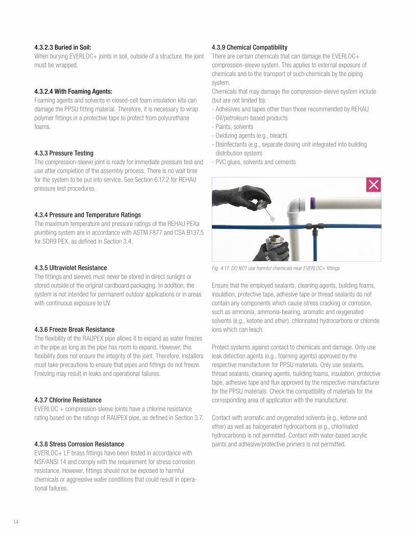
4.3.9 Chemical CompatibilityTherearecertainchemicalsthatcandamagetheEVERLOC+compression-sleevesystem.Thisappliestoexternalexposureofchemicalsandtothetransportofsuchchemicalsbythepipingsystem.Chemicalsthatmaydamagethecompression-sleevesysteminclude(butarenotlimitedto):-AdhesivesandtapesotherthanthoserecommendedbyREHAU-Oil/petroleum-basedproducts-Paints,solvents-Oxidizingagents(e.g.,bleach)-Disinfectants(e.g.,separatedosingunitintegratedintobuildingdistributionsystem)-PVCglues,solventsandcements
Fig. 4.17: DO NOT use harmful chemicals near EVERLOC+ fittings
Ensurethattheemployedsealants,cleaningagents,buildingfoams,insulation,protectivetape,adhesivetapeorthreadsealantsdonotcontainanycomponentswhichcausestresscrackingorcorrosion,suchasammonia,ammonia-bearing,aromaticandoxygenatedsolvents(e.g.,ketoneandether),chlorinatedhydrocarbonsorchlorideionswhichcanleach.
Protectsystemsagainstcontacttochemicalsanddamage.Onlyuseleakdetectionagents(e.g.,foamingagents)approvedbytherespectivemanufacturerforPPSUmaterials.Onlyusesealants,threadsealants,cleaningagents,buildingfoams,insulation,protectivetape,adhesivetapeandfluxapprovedbytherespectivemanufacturerforthePPSUmaterials.Checkthecompatibilityofmaterialsforthecorrespondingareaofapplicationwiththemanufacturer.
Contactwitharomaticandoxygenatedsolvents(e.g.,ketoneandether)aswellashalogenatedhydrocarbons(e.g.,chlorinatedhydrocarbons)isnotpermitted.Contactwithwater-basedacrylicpaintsandadhesive/protectiveprimersisnotpermitted.
14

4.3.10 Copper SolderingPropersolderingtechniquesmustbefollowedwhensolderingallcompression-sleevefittingsaccordingtotheCopper Development Association (CDA) Handbook: -Thesurfaceofthefittingsolderingareamustbeproperlycleanedforagoodsolderconnection.Applyingfluxisnotconsideredsufficientcleaningforthesolderingarea.Usingapropersandingorbrushtechniqueisnecessarytoremovethesurfaceoxides.Inordertopreventfurtherformationofoxides,thefluxshouldbeappliedimmediatelyafterthecleaningprocess.Aproperfluxthatiscompatiblewiththebrassalloymustbeused.-Caremustbetakentonotoverheatthesolderingsurfaceasthiscanleadtotheformationofoxidespreventinggoodadhesionofthesoldermaterial.Itisimperativethatthefittingisheatedevenlyaroundtheentiresurfacesoastonotoverheatoneparticulararea.-Allcompletedsolderjointsmustbetestedforjointintegrityfollowingtheproceduresprescribedbyprevailinglocalcodes.
4.4 EVERLOC+ Compression-sleeve ToolsAssemblingtheEVERLOC+compression-sleevesystemrequirestheuseoftheEVERLOC+compression-sleevetools.OnlymakeEVERLOC+compression-sleevejointswiththesetools.
Beforeuse,readandunderstandthefollowingsafetysymbolswhicharefoundontheEVERLOC+compression-sleevetools.
SafetyAlertSymbol–Toreducetheriskofinjury,followthespecifiedsafetyinstructions.
Readandfollowallsafetyprecautionsintheinstructionmanual.Improperusecanleadtoseriouspersonalinjuryorpropertydamage.
Toreducetheriskofseriouseyeinjury,alwayswearproper eye protection.
Riskofelectricshock.Neveroperatethepowertoolindamporwetconditions.Neverexposetorainorsubmergeinwaterorotherliquids.Neveroperatethepowertoolnearwiresorcablescarryingelectriccurrent.
Toreducetheriskofseverepersonalinjury,includingcrushandlacerationinjury,keepfingers,handsandallpartsofyourbodyawayfromtheexpanderhead,hydraulicslideandcompressionjawsduringoperation.
NOTICEUseonlyEVERLOC+compression-sleevetoolsforassemblyandinstallation.Useofothertoolswillresultinanimproperlyassembledjoint,whichmayresultinleakingandpropertydamage.
4.4.1 EVERLOC+ Power Tool 3/8 to 1 in.ForassemblyofEVERLOC+fittingsinsizes3/8through1in.UsetheEVERLOC+powertool.RefertoEVERLOC+ Power Tool Product Instruction Manual (855.725)foracompleteunderstandingofoperation,careanduseofthetool
Fig. 4.18: EVERLOC+ power tool
EVERLOC+powertoolstandardkit,Art.105107-001:-EVERLOC+powertool-Expansionadapter-1/2,3/4and1in.EVERLOC+expanderheads(quickchange)-1/2,3/4and1in.EVERLOC+compressionjaws-DEWALT®12VLi-ionbattery(DCB127)(2batteriesperkit)-DEWALT12V/20VLi-ioncharger120VAC(DCB107)-DEWALT12V/20VLi-ionBatteryChargerInstructionManual-Pipe cutter-Lubricant-Cleaningbrush-Tool case-Product Instruction Manual
Fig. 4.19: EVERLOC+ power tool standard kit
AvailableAccessories:-3/8in.expanderhead(quickchange)-3/8in.compressionjaws-5/8in.expanderhead(quickchange)-5/8in.compressionjaws
15
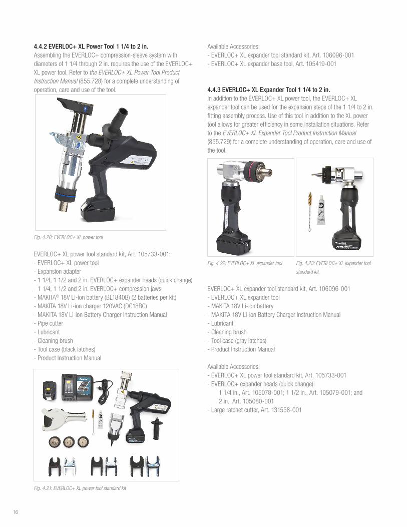
4.4.2 EVERLOC+ XL Power Tool 1 1/4 to 2 in.AssemblingtheEVERLOC+compression-sleevesystemwithdiametersof11/4through2in.requirestheuseoftheEVERLOC+XLpowertool.Refertothe EVERLOC+ XL Power Tool Product Instruction Manual(855.728)foracompleteunderstandingofoperation,careanduseofthetool.
Fig. 4.20: EVERLOC+ XL power tool
EVERLOC+XLpowertoolstandardkit,Art.105733-001:-EVERLOC+XLpowertool-Expansionadapter-11/4,11/2and2in.EVERLOC+expanderheads(quickchange)-11/4,11/2and2in.EVERLOC+compressionjaws-MAKITA®18VLi-ionbattery(BL1840B)(2batteriesperkit)-MAKITA18VLi-ioncharger120VAC(DC18RC)-MAKITA18VLi-ionBatteryChargerInstructionManual-Pipe cutter-Lubricant-Cleaningbrush-Toolcase(blacklatches)-Product Instruction Manual
Fig. 4.21: EVERLOC+ XL power tool standard kit
AvailableAccessories:-EVERLOC+XLexpandertoolstandardkit,Art.106096-001-EVERLOC+XLexpanderbasetool,Art.105419-001
4.4.3 EVERLOC+ XL Expander Tool 1 1/4 to 2 in. InadditiontotheEVERLOC+XLpowertool,theEVERLOC+XLexpandertoolcanbeusedfortheexpansionstepsofthe11/4to2in.fittingassemblyprocess.UseofthistoolinadditiontotheXLpowertoolallowsforgreaterefficiencyinsomeinstallationsituations.RefertotheEVERLOC+ XL Expander Tool Product Instruction Manual (855.729)foracompleteunderstandingofoperation,careanduseofthetool.
Fig. 4.22: EVERLOC+ XL expander tool Fig. 4.23: EVERLOC+ XL expander tool
standard kit
EVERLOC+XLexpandertoolstandardkit,Art.106096-001-EVERLOC+XLexpandertool-MAKITA18VLi-ionbattery-MAKITA18VLi-ionBatteryChargerInstructionManual-Lubricant-Cleaningbrush-Toolcase(graylatches)-Product Instruction Manual
AvailableAccessories:-EVERLOC+XLpowertoolstandardkit,Art.105733-001-EVERLOC+expanderheads(quickchange):
11/4in.,Art.105078-001;11/2in.,Art.105079-001;and2in.,Art.105080-001
-Largeratchetcutter,Art.131558-001
16

5. DESIGN CONSIDERATIONS
5.1 Pipe SizingThedesignandlayoutofthebuildinghot-andcold-waterdistributionsystemshallcomplywithacceptedplumbingengineeringpracticeandasperprevailinglocalcodes.
TheREHAUPEXaplumbingsystemconsistsofRAUPEXUVshieldPEXapipeandtheEVERLOC+compression-sleevefittingsystemandcanbedesignedandsizedperthefollowingmodelplumbingcodes:
- ICCInternationalPlumbingCode(IPC) - ICCInternationalResidentialCode(IRC) - IAMPONationalStandardPlumbingCode(NSPC) - IAPMOUniformPlumbingCode(UPC) - NRCCNationalPlumbingCodeofCanada(NPCC)
Inaddition,aproperlydesignedplumbingsystemshouldfollowtheengineeringprinciplesaspertheAmericanSocietyofPlumbingEngineers(ASPE)Plumbing Engineering Design Handbook Volume II orequivalent.
Forsizingasysteminresidentialandlightcommercialbuildings,usethewatersupplyfixtureunit(WSFU)methodtodeterminetherequiredload(GPM)andresultingpipesizeaspublishedinthemodelplumbingcodes.Alternatively,orinlargerbuildings,theuniformfrictionheadlossmethodcanbeutilized.
5.1.1 Standard Dimension RatioRAUPEXpipeisinaccordancetothedimensionalstandardsinASTMF876andCSAB137.5.RAUPEXiscoppertubesize(CTS)outsidediameter(OD)whichmeansthattheactualODofthepipeis1/8in.(3.18mm)largerthanthenominalsize.
Wallthicknessisdefinedbythestandarddimensionalratio(SDR).RAUPEXUVshieldpipeisSDR9,whichequatestotheoutsidediameterbeingapproximatelyninetimesthewallthickness.SincePEXpipehasathickerwallthancoppertube,theinsidediameter(ID)isslightlysmaller.However,sincePEXpipeisnotsusceptibletotheerosionandcorrosionissuesofcoppertube,plumbingsystemscanbedesignedathighervelocitieswhichallowforcomparablesizingofasystem.
5.1.2 Determining Friction LossThepressurelossfortheREHAUPEXaplumbingsystemcanbecalculatedusingtheREHAU PEXa Piping Systems Pressure Loss Tables (855.861)availableonlineontheREHAUResourceCenterorusingtheREHAULoopCADsoftwarepressurelosscalculatortool.
5.1.3 Velocity ConsiderationsThemaximumvelocityofwaterflow(feet/second–fps)intheplumbingsystemshouldbeconsideredwhensizingaREHAUPEXaplumbingsystem.Todeterminethepipesize,theWSFUloadcanbecorrelatedtoflowrate(GPM)fromtablespublishedinthemodelplumbingcodes.
Oncetheflowrateisdetermined,thepipecanbesizedbasedontheallowablemaximumvelocitiesperprevailinglocalcodes.
Thedesignercanusethefollowingtablesasaguideline:
Table 5.1: Maximum Velocity of Water Flow
Cold-Water
Piping
- Typicalplumbingcodesstatemaximumvelocityof8ft/sec
- REHAUrecommendsamaximumdesignvelocityof10ft/sec
Hot-Water
Piping
- Typicalplumbingcodesstatemaximumvelocityof5ft/sec
- REHAUrecommendsamaximumdesignvelocityof8ft/sec
Hot-Water
Recirculation
Return Piping
- Maximumvelocityof2ft/sec
- Maximumoperatingtemperatureof140°F(60°C)
Table 5.2: GPM per Pipe Size
Pipe SizeGPM
@ 2 fpsGPM
@ 5 fpsGPM
@ 8 fpsGPM
@ 10 fps
3/8in 0.6 1.6 2.5 3.2
1/2in 1.1 2.9 4.6 5.8
3/4in 2.3 5.7 9.1 11.3
1 in. 3.8 9.4 15.0 18.8
11/4in 5.7 14.0 22.3 28.1
11/2in 8.0 19.7 31.3 39.1
2 in 13.7 33.4 53.8 67.1
17

5.2 Equivalent Length of FittingsItiscommonpracticefordesignerstoconvertthepressuredropacrossfittingstoanaverageequivalentlengthofpipe.Theseequivalentlengthsareaddedtothetotalpipelength.Designerscanthencalculatetotalpressurelossusingthisadjustedpipingsystemlength.
Table 5.3: Equivalent Length of Fittings
CouplingsFitting Description Equivalent Length (ft)
3/8x3/8in.EVERLOC+LFBrassCoupling 1.1
1/2x1/2in.EVERLOC+PolymerCoupling 0.4
5/8x5/8in.EVERLOC+LFBrassCoupling 1.0
3/4x1/2in.EVERLOC+PolymerCoupling 2.1
3/4x3/4in.EVERLOC+PolymerCoupling 0.8
1x3/4in.EVERLOC+PolymerCoupling 2.7
1x1in.EVERLOC+PolymerCoupling 1.1
11/4x11/4in.EVERLOC+PolymerCoupling 2.0
11/2x11/2in.EVERLOC+PolymerCoupling 2.0
2x1in.EVERLOC+LFBrassCoupling 5.2
2x11/4in.EVERLOC+LFBrassCoupling 5.3
2x11/2in.EVERLOC+LFBrassCoupling 6.1
Tees
Fitting Description
Equivalent Length (ft)
RUN
Equivalent Length (ft) BRANCH
1/2x1/2x1/2in.EVERLOC+PolymerTee 0.8 4.4
1/2x1/2x3/4in.EVERLOC+PolymerTee - 4.1
3/4x1/2x1/2in.EVERLOC+PolymerTee 2.4 4.3
3/4x1/2x3/4in.EVERLOC+PolymerTee 2.4 7.6
3/4x3/4x1/2in.EVERLOC+PolymerTee 1.3 4.0
3/4x3/4x3/4in.EVERLOC+PolymerTee 1.2 7.6
3/4x3/4x1in.EVERLOC+PolymerTee - 6.8
1x1x1/2in.EVERLOC+PolymerTee 1.6 3.9
1x3/4x3/4in.EVERLOC+PolymerTee 2.8 6.5
1x3/4x1in.EVERLOC+PolymerTee 3.1 10.9
1x1x3/4in.EVERLOC+PolymerTee 1.2 6.7
1x1x1in.EVERLOC+PolymerTee 1.6 10.6
11/4x1x1in.EVERLOC+PolymerTee 3.8 9.7
11/4x11/4x1in.EVERLOC+PolymerTee 2.3 10.1
11/4x11/4x11/4in.EVERLOC+PolymerTee 2.2 14.4
11/2x11/2x11/2in.EVERLOC+PolymerTee 2.6 17.0
2x2x11/2in.EVERLOC+LFBrassTee 1.9 10.9
Elbows (PEX to PEX)Fitting Description Equivalent Length (ft)
1/2x1/2in.EVERLOC+PolymerElbow 1.9
5/8x5/8in.EVERLOC+LFBrassElbow 5.4
3/4x3/4in.EVERLOC+PolymerElbow 7.0
1x1in.EVERLOC+PolymerElbow 10.7
11/4x11/4in.EVERLOC+PolymerElbow 14.2
11/2x11/2in.EVERLOC+PolymerElbow 16.0
2x2in.EVERLOC+PolymerElbow 24.2
Elbows (PEX to transition)
Fitting DescriptionEquivalent Length (ft)
1/2x1/2in.CMaleor3/8in.CFemaleEVERLOC+LFBrassElbow 7.4
3/4x3/4in.CMaleEVERLOC+LFBrassElbow 7.4
1/2x1/2in.MPTEVERLOC+LFBrassDropEarElbow 7.6
3/4x3/4in.MPTEVERLOC+LFBrassDropEarElbow 7.5
Adapters (PEX to copper)
Fitting DescriptionEquivalent Length (ft)
1/2x1/2in.CFemaleEVERLOC+LFBrassAdapter 2.3
1/2x1/2in.CMaleor3/8in.CFemaleEVERLOC+LFBrassAdptr 2.4
3/4x1in.CFemaleEVERLOC+LFBrassAdapter 3.9
3/4x3/4in.CFemaleEVERLOC+LFBrassAdapter 2.7
3/4x3/4in.CMaleEVERLOC+LFBrassAdapter 2.6
1x1in.CFemaleEVERLOC+LFBrassAdapter 3.5
1x1in.CMaleEVERLOC+LFBrassAdapter 3.3
11/4x11/4in.CFemaleEVERLOC+LFBrassAdapter 4.1
11/4x11/4in.CMaleEVERLOC+LFBrassAdapter 4.3
11/2x11/2in.CFemaleEVERLOC+LFBrassAdapter 5.3
11/2x11/2in.CMaleEVERLOC+LFBrassAdapter 5.4
2x2in.CFemaleEVERLOC+LFBrassAdapter 7.0
2x2in.CMaleEVERLOC+LFBrassAdapter 6.9
Adapters (PEX to MPT/FPT)
Fitting DescriptionEquivalent Length (ft)
1/2x1/2in.MPTEVERLOC+LFBrassAdapter 3.3
3/4x3/4in.FPTEVERLOC+LFBrassAdapter 2.8
3/4x3/4in.MPTEVERLOC+LFBrassAdapter 3.4
3/4x1in.MPTEVERLOC+LFBrassAdapter 4.3
1x1in.FPTEVERLOC+LFBrassAdapter 3.6
1x1in.MPTEVERLOC+LFBrassAdapter 3.8
11/4x11/4in.MPTEVERLOC+LFBrassAdapter 4.9
11/2x11/2in.MPTEVERLOC+LFBrassAdapter 5.9
2x2in.MPTEVERLOC+LFBrassAdapter 7.3
18

5.3 Piping Layouts Mostpipinglayoutdesignsutilizesomeformofreducingteeinordertobranchfromamaintrunklinetosmallerpipediametersthatroutetofixturesandappliances.TheflexibilityofRAUPEXpipeallowsyoutoeasilyroutearoundobstaclesandreducethenumberoffittingsneeded.Multi-portteesfunctionlikereducingtees,butreducethenumberofconnectionpoints.Ingeneral,thebestsystemdesignsutilizetheflexibilityoftheRAUPEXpipeandminimizeconnections.
5.3.1 Tee and Branch - IncreasesinstallationspeedbytakingadvantageoftheflexibilityofPEXapipe - Reducespressureatthefurthestfixture - Similartotraditionalrigidpipeinstallationlayouts - Reduceshotwaterwaittime,comparedtoahome-runsystem
Parts list: - Reducingtees - Straighttees - Straightorcoiledpipe
Fig. 5.1: Tee and branch piping layout
5.3.2 Multi-port Tee - Minimizesnumberofconnections - Combinesteeandbranchandhome-runconcepts - Systemsarepressure-balancedateachmanifold - Reduceshotwaterwaittime,comparedtoahome-runsystem
Parts list: - Flow-throughmulti-porttees - Closed-endmulti-porttees - Straightorcoiledpipe
Fig. 5.2: Multi-port tee piping layout
5.3.3 Home-run - Generallyforresidentialinstallations - Eliminatesmostfittings - Balancespressuretoallfixtures - Increaseshotwaterwaittime,comparedtoteeandbranchandremotemulti-portdesigns - Usesmorepipe - Mayrequiremoreholestobedrilledinjoistspaces
Parts list: - Multi-porttees - Straightorcoiledpipe
Fig. 5.3: Home-run piping layout
19

5.4 Thermal Expansion and ContractionWhenthermalexpansionisanticipated,pipemovementshouldbecontrolledtoavoidchangesthatcoulddamagethepipingsystem.Anchoringanduseofexpansionloopsmaybeusedtoaccomplishthis.Allowingforcontrolledexpansionandcontractioninmultiplepartsofapipingsystemisanacceptedmeansofpreventingaddedstressesinotherpartsofthesystem.
RAUPEXpipingsystemsexhibitahigherexpansionandcontractionratewhensubjectedtochangesintemperatureascomparedtometallicpipingsystems.Becauseofitslowermodulusofelasticity,RAUPEXpipeislessrigidthanmetallicpipinganddevelopslessforcethanmetallicpipewhenexposedtotemperaturechanges.
5.4.1 Calculating Thermal Expansion of RAUPEX PipeWhenapipeisanchoredatoneendbutcanotherwisefreelymoveintheaxialdirection,anincreaseintemperaturecausesthepipetoincreaseinoveralllength.Adecreaseintemperaturecausesadecreaseinlength.
Thefollowingequationpredictsthenetexpansion/contractioninthelengthofafullyunrestrainedpipethatoccursinconsequenceofagivenchangeintemperature:
(1)
where,ΔL=changeinpipelength,in.α=coefficientoflinearexpansion/contraction,in/ft°FL=initialpipelength,in.ΔT=changeinpipetemperature,°FNote:SeeTable3.1forcoefficientoflinearexpansion
5.4.2 Calculating L-bend and U-bend for RAUPEX PipeRAUPEXpipewillexpandandcontractwhenheatedorcooledduetoachangeinwatertemperatureorambienttemperature.ThermalexpansionofRAUPEXpipemustbeconsideredinthedesignandinstallationofthepipingsystem.Fixedanchorpoints,guidesandexpansionloopsshouldbeutilizedtoaccountfortheexpansionandcontractionofthepipetopreventanydamagetothepipingsystem.
Fig. 5.4: L-bend and U-bend
CalculationofthelengthofoffsetforanL-bendorwidthandheightofaU-bendcanbedeterminedasfollows,whereL=lengthofoffsetlegforL-bend(ft),perASHRAE2016 Chap 46 Pipe, Tubes and Fittings
(2)
D=actualpipeoutsidediameter(in),sourceforRAUPEXisTable3.2E=modulusofelasticity(psi),sourceforRAUPEXisTable3.1C=constant,144(in²/ft²)S
A=allowablestressrange
FP=FixedPoint
SP=SlidingPoint(Guide)
𝐿 = �3𝛥𝐷𝐸𝐶𝑆𝐴
20

andΔ=anchor-to-anchorthermalexpansionorcontraction(in)
(3)
where,α=coefficientoflinearexpansion([in/[ft°F]),sourceforRAUPEXisTable3.1dT=temperaturedifferential(°F)L
FP=singleplanelengthbetweenfixedpoints(anchors)(ft)
ThewidthofaU-bendiscalculatedwiththefollowingequation,whereW=widthofU-bend(ft),perASHRAE2016 Chap 46 Pipe, Tubes and Fittings
(4)
TheheightofaU-bendiscalculatedwiththefollowingequation,whereH=heightofU-bend(ft),perASHRAE2016 Chap 46 Pipe, Tubes and Fittings
(5)
5.4.3 RisersAlwayscomplywithprevailinglocalcodesregardingtheuseofPEXpipeinriserapplications.RAUPEXshouldbesupportedverticallyeveryfloor(notexceeding10ft[3.048m]perfloor).Apipeguideshouldbeusedmidwaybetweenverticalsupports.Themid-storyguidesdonotsupporttheweightofthepipe;theykeepitfrommovinghorizontallywhenthepipeexpands.
Note:ThesearetheminimumrequirementsoftheUMC,UPC,IMC,IPCandIRC.
Whenitcomestohydronicrisers,thegoalistocontrolexpansionandcontractionforcesinsidethewallcavityandupholdtheintegrityofthefirestop.Toaccomplishthis,ariserclampshouldbeplacedatthefloorandbaseofeachlevel,alongwithamid-storyguide.Pipingrunsmustcomplywithsupportspacingasdefinedbytheprevailinglocalcodes.
5.5. Installation in Fire-rated AssembliesIncommercialandresidentialapplications,fire-ratedwallandfloor/ceilingassembliesareanessentialcomponentoftheoverallfireresistantconstructionforthebuilding.Themodelbuildingcodesdefinetherequirementsfortheseratedassemblies,whichincludesthetypeofconstruction(framedorconcrete),thefireratingoftheassembly(2hours,forexample),andloading.
Forplumbinginstallations,itiscommontoroutethepipingthroughtheseratedassemblies.Inthiscase,themodelbuildingcodesrequirethattheinstalledcomponentsdonotdiminishtheoverallratingoftheassembly.Therefore,REHAUhascompletedaseriesoffiretestswithULandULCtoevaluatetheperformanceofREHAUpipinginthesetypesofinstallations.
Basedonthisextensivetesting,ithasbeendemonstratedthattheinclusionofRAUPEXpipeshouldnotadverselyaffecttheoverallfireratingoftheassembly.RAUPEXpipeisULandULCListedforinstallationinfire-ratedassemblieswhichincludesreinforcedconcreteslabs,wood-framedfloor/ceilingassemblies,framedbearingwalls,andframednon-bearingwalls.ThislistingcoversUVshieldpipesinsizes3/8through2in.
ThefireresistancelistingsforRAUPEXpipehavebeentestedtoandmeetthefollowingstandards:-ANSI/UL263,Fire Tests of Building Construction and Materials -CAN/ULC-S101,Standard Methods of Fire Endurance Tests of
Building Construction and Materials
ThefollowingdesignlistingscanbefoundontheULandULConlinecertificationsdirectory(www.ul.com and www.ulc.ca).
Table 5.4: Fire-rated Assembly Design Listings
Assembly Description UL Design No. ULC Design No.
ReinforcedConcreteSlab No.K917 No. J900
WoodFramedFloor/CeilingAssembly No.L588 No.M516
CombustibleBearingWall No.U383 No. W316
CombustibleNon-bearingWall No.V461 No.W458
WhenusingRAUPEXpipeinthesetypesofapplications,thespecify-ingengineeranddesignershouldevaluatethedesignlistingstoensureprevailinglocalcoderequirementsaremet.Inadditiontheauthorityhavingjurisdictionshouldreviewandapprovethedesignbeforeinstallation.
5.5.1 Firestop SystemsInaccordancewithmodelbuildingcodes,whenRAUPEXpipepenetratesthroughafire-ratedassembly(i.e.,floor,ceiling,wall)thepenetrationmustbeprotectedbyanapprovedthrough-penetrationfirestopsystem.Thisfirestopsystemshallbetestedinaccordance
𝛥 = 𝛼 ∗ 𝑑𝑇 ∗ 𝐿𝐹𝑝
𝑊 =𝐿5
𝐻 = 2𝑊
21

withoneorallofthefollowingstandardsandlistedbyanindependentthird-partylistingagencysuchasUL,ULCorITS(WarnockHersey).Thefirestopsystemshallmeetalllocalcoderequirementspriortoinstallation.
Mostcommonfirestopsystemstandardsare:-ASTME814,Fire Tests of Through-Penetration Firestops-UL1479,Fire Tests of Through-Penetration Firestops-CAN/ULCS115,Tests of Fire Resistance of Building Joint Systems
SeveralsuchsystemsarecommonlyavailableacrossNorthAmerica.InordertochooseanapprovedfirestopsystemforeachspecificapplicationwhereaPEXpipepenetratesafire-ratedassembly,thefollowinginformationmustfirstbeknown:-NominalsizeofPEXpipepenetratingthefire-ratedassembly-NumberofPEXpipespenetratingthroughoneopening-Typeofassemblybeingpenetrated(i.e.floor,wall,ceiling)-Constructionoffire-ratedassembly(i.e.wood,concrete)-The"F"and"T"ratingsofthefire-ratedassembly
Fig. 5.5: RAUPEX pipe is fire-stopped at both points of entry through the assembly
Todetermineaproductthatislocallyavailableandcorrectfortheassemblytype,REHAUrecommendscustomerscontactlocalfirestopproductsupplierstodeterminewhichoftheirfirestopproductsarelistedfortheintendedassemblywithPEXpipe:
5.5.2 Installation in Plenum Space (United States)Aplenumisdefinedasanenclosedportionofthebuildingstructurethatisdesignedtoallowairmovement,therebyservingaspartofanairdistributionsystem.Plenumscanserveassupply,return,exhaustandventilationportionsoftheairdistributionsystem.
TheInternationalMechanicalCode(IMC)andUniformMechanicalCode(UMC)requirethatcombustiblematerialsinstalledwithinairplenumshaveaflamespread(FS)indexofnotmorethan25,andasmokedeveloped(SD)indexofnotmorethan50.Thesenumbersdonotcontainunits,andareusedasindex(comparative)ratingsofhow
quicklybuildingmaterialsburnandhowmuchsmokeisdevelopedwhentheyburn.Pipesthatmeettheserequirementsaresometimessaidtohavea"plenumrating."
Theflamespreadindexandthesmokedevelopedindexaremeasuredduringastandardizedlaboratorytestthatburnscombustiblepipeandmeasuresthespeedofflamespreadandvolumeofsmokedeveloped.
TheIMCandUMCspecifythattheflamespreadindexandthesmokedevelopedindexofamaterialaretobedeterminedbasedononeofthefollowingstandards:-ASTME84,Standard Test Method for Surface Burning Characteris-
tics of Building Materials, or-UL723, Test for Surface Burning Characteristics of Building
Materials
ThefollowingsizesofRAUPEXUVshieldpipearelistedwithaflamespreadindexofnotmorethan25andasmokedevelopedindexofnotmorethan50.
Table 5.5: Flame Spread/Smoke Developed ≤ 25/50 Bare Pipe
Pipe Description
ASTM E84 18 in. spacing
FS/SD
1/2in.RAUPEXUVshield FS≤25/SD≤50
Table 5.6: Flame Spread/Smoke Developed ≤ 25/50 Bare Pipe with REHAU Galvanized Support Channel
Pipe Description
ASTM E84 Galvanized support channel
FS/SD
3/4-2in.RAUPEXUVshield FS≤25/SD≤50
Table: 5.7: Flame Spread/Smoke Developed ≤ 25/50 with 1/2 in. Fiberglass Insulation
Pipe Description
ASTM E84 Pipe wrapped in 1/2 in. fiberglass insulation
FS/SD
≤2in.RAUPEXUVshield FS≤25/SD≤50
22
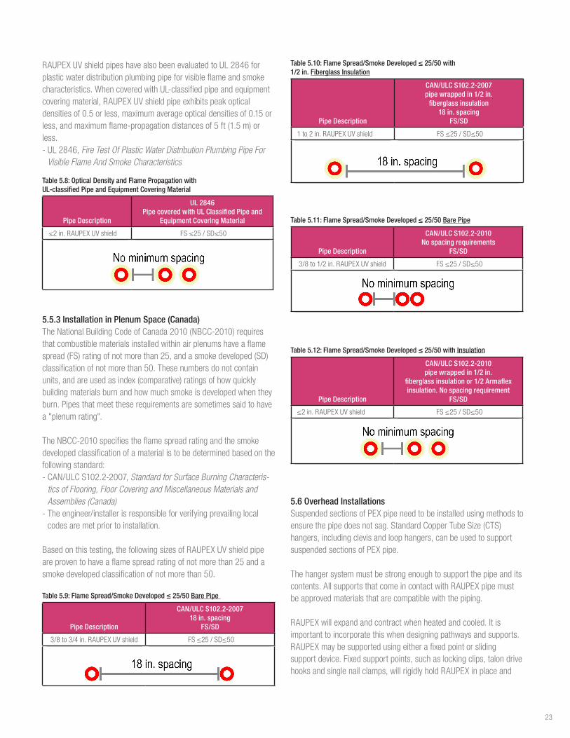
RAUPEXUVshieldpipeshavealsobeenevaluatedtoUL2846forplasticwaterdistributionplumbingpipeforvisibleflameandsmokecharacteristics.WhencoveredwithUL-classifiedpipeandequipmentcoveringmaterial,RAUPEXUVshieldpipeexhibitspeakopticaldensitiesof0.5orless,maximumaverageopticaldensitiesof0.15orless,andmaximumflame-propagationdistancesof5ft(1.5m)orless.-UL2846,Fire Test Of Plastic Water Distribution Plumbing Pipe For
Visible Flame And Smoke Characteristics
Table 5.8: Optical Density and Flame Propagation with UL-classified Pipe and Equipment Covering Material
Pipe Description
UL 2846Pipe covered with UL Classified Pipe and
Equipment Covering Material
≤2in.RAUPEXUVshield FS≤25/SD≤50
5.5.3 Installation in Plenum Space (Canada)TheNationalBuildingCodeofCanada2010(NBCC-2010)requiresthatcombustiblematerialsinstalledwithinairplenumshaveaflamespread(FS)ratingofnotmorethan25,andasmokedeveloped(SD)classificationofnotmorethan50.Thesenumbersdonotcontainunits,andareusedasindex(comparative)ratingsofhowquicklybuildingmaterialsburnandhowmuchsmokeisdevelopedwhentheyburn.Pipesthatmeettheserequirementsaresometimessaidtohavea"plenumrating".
TheNBCC-2010specifiestheflamespreadratingandthesmokedevelopedclassificationofamaterialistobedeterminedbasedonthefollowingstandard:-CAN/ULCS102.2-2007,Standard for Surface Burning Characteris-
tics of Flooring, Floor Covering and Miscellaneous Materials and Assemblies (Canada)-Theengineer/installerisresponsibleforverifyingprevailinglocalcodesaremetpriortoinstallation.
Basedonthistesting,thefollowingsizesofRAUPEXUVshieldpipeareproventohaveaflamespreadratingofnotmorethan25andasmokedevelopedclassificationofnotmorethan50.
Table 5.9: Flame Spread/Smoke Developed ≤ 25/50 Bare Pipe
Pipe Description
CAN/ULC S102.2-200718 in. spacing
FS/SD
3/8to3/4in.RAUPEXUVshield FS≤25/SD≤50
Table 5.10: Flame Spread/Smoke Developed ≤ 25/50 with 1/2 in. Fiberglass Insulation
Pipe Description
CAN/ULC S102.2-2007pipe wrapped in 1/2 in.
fiberglass insulation 18 in. spacing
FS/SD
1to2in.RAUPEXUVshield FS≤25/SD≤50
Table 5.11: Flame Spread/Smoke Developed ≤ 25/50 Bare Pipe
Pipe Description
CAN/ULC S102.2-2010No spacing requirements
FS/SD
3/8to1/2in.RAUPEXUVshield FS≤25/SD≤50
Table 5.12: Flame Spread/Smoke Developed ≤ 25/50 with Insulation
Pipe Description
CAN/ULC S102.2-2010pipe wrapped in 1/2 in.
fiberglass insulation or 1/2 Armaflex insulation. No spacing requirement
FS/SD
≤2in.RAUPEXUVshield FS≤25/SD≤50
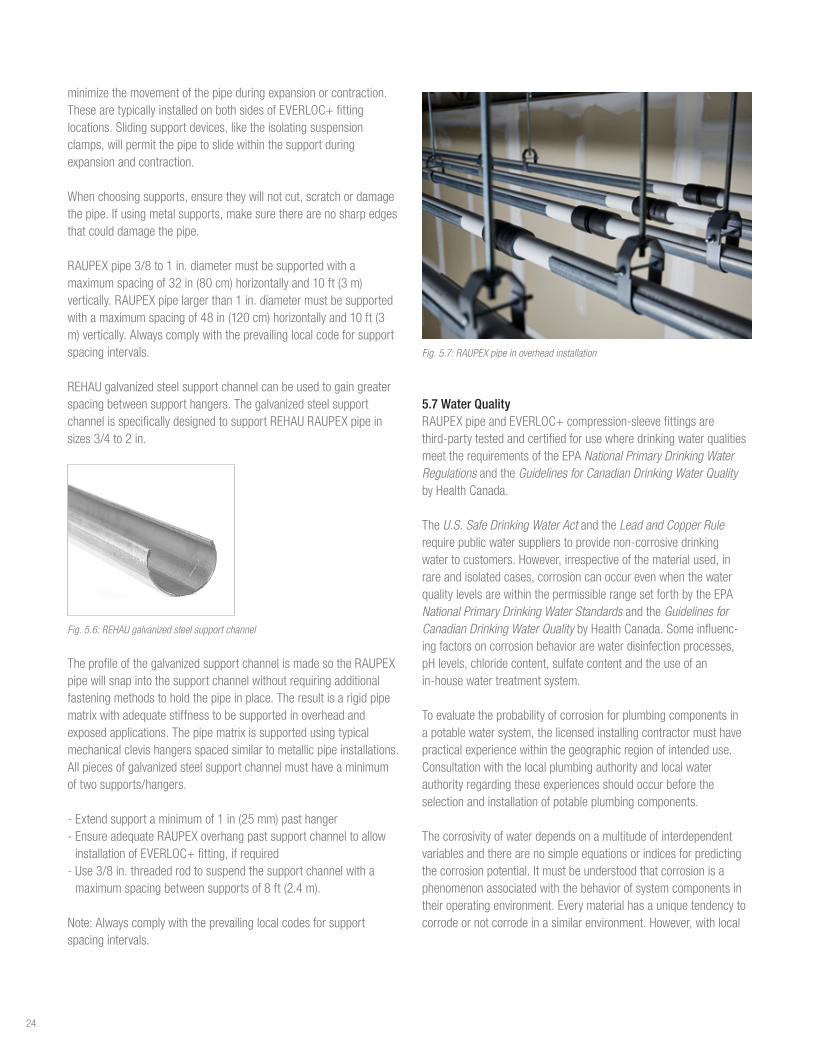
5.6 Overhead InstallationsSuspendedsectionsofPEXpipeneedtobeinstalledusingmethodstoensurethepipedoesnotsag.StandardCopperTubeSize(CTS)hangers,includingclevisandloophangers,canbeusedtosupportsuspendedsectionsofPEXpipe.
Thehangersystemmustbestrongenoughtosupportthepipeanditscontents.AllsupportsthatcomeincontactwithRAUPEXpipemustbeapprovedmaterialsthatarecompatiblewiththepiping.
RAUPEXwillexpandandcontractwhenheatedandcooled.Itisimportanttoincorporatethiswhendesigningpathwaysandsupports.RAUPEXmaybesupportedusingeitherafixedpointorslidingsupportdevice.Fixedsupportpoints,suchaslockingclips,talondrivehooksandsinglenailclamps,willrigidlyholdRAUPEXinplaceand
23
minimizethemovementofthepipeduringexpansionorcontraction.ThesearetypicallyinstalledonbothsidesofEVERLOC+fittinglocations.Slidingsupportdevices,liketheisolatingsuspensionclamps,willpermitthepipetoslidewithinthesupportduringexpansionandcontraction.
Whenchoosingsupports,ensuretheywillnotcut,scratchordamagethepipe.Ifusingmetalsupports,makesuretherearenosharpedgesthatcoulddamagethepipe.
RAUPEXpipe3/8to1in.diametermustbesupportedwithamaximumspacingof32in(80cm)horizontallyand10ft(3m)vertically.RAUPEXpipelargerthan1in.diametermustbesupportedwithamaximumspacingof48in(120cm)horizontallyand10ft(3m)vertically.Alwayscomplywiththeprevailinglocalcodeforsupportspacingintervals.
REHAUgalvanizedsteelsupportchannelcanbeusedtogaingreaterspacingbetweensupporthangers.ThegalvanizedsteelsupportchannelisspecificallydesignedtosupportREHAURAUPEXpipeinsizes3/4to2in.
Fig. 5.6: REHAU galvanized steel support channel
TheprofileofthegalvanizedsupportchannelismadesotheRAUPEXpipewillsnapintothesupportchannelwithoutrequiringadditionalfasteningmethodstoholdthepipeinplace.Theresultisarigidpipematrixwithadequatestiffnesstobesupportedinoverheadandexposedapplications.Thepipematrixissupportedusingtypicalmechanicalclevishangersspacedsimilartometallicpipeinstallations.Allpiecesofgalvanizedsteelsupportchannelmusthaveaminimumoftwosupports/hangers.
- Extendsupportaminimumof1in(25mm)pasthanger - EnsureadequateRAUPEXoverhangpastsupportchanneltoallowinstallationofEVERLOC+fitting,ifrequired - Use3/8in.threadedrodtosuspendthesupportchannelwithamaximumspacingbetweensupportsof8ft(2.4m).
Note:Alwayscomplywiththeprevailinglocalcodesforsupportspacingintervals.
Fig. 5.7: RAUPEX pipe in overhead installation
5.7 Water QualityRAUPEXpipeandEVERLOC+compression-sleevefittingsarethird-partytestedandcertifiedforusewheredrinkingwaterqualitiesmeettherequirementsoftheEPANational Primary Drinking Water RegulationsandtheGuidelines for Canadian Drinking Water Quality byHealthCanada.
TheU.S. Safe Drinking Water Actandthe Lead and Copper Rule requirepublicwatersupplierstoprovidenon-corrosivedrinkingwatertocustomers.However,irrespectiveofthematerialused,inrareandisolatedcases,corrosioncanoccurevenwhenthewaterqualitylevelsarewithinthepermissiblerangesetforthbytheEPANational Primary Drinking Water Standards andtheGuidelines for Canadian Drinking Water QualitybyHealthCanada.Someinfluenc-ingfactorsoncorrosionbehaviorarewaterdisinfectionprocesses,pHlevels,chloridecontent,sulfatecontentandtheuseofanin-housewatertreatmentsystem.
Toevaluatetheprobabilityofcorrosionforplumbingcomponentsinapotablewatersystem,thelicensedinstallingcontractormusthavepracticalexperiencewithinthegeographicregionofintendeduse.Consultationwiththelocalplumbingauthorityandlocalwaterauthorityregardingtheseexperiencesshouldoccurbeforetheselectionandinstallationofpotableplumbingcomponents.
Thecorrosivityofwaterdependsonamultitudeofinterdependentvariablesandtherearenosimpleequationsorindicesforpredictingthecorrosionpotential.Itmustbeunderstoodthatcorrosionisaphenomenonassociatedwiththebehaviorofsystemcomponentsintheiroperatingenvironment.Everymaterialhasauniquetendencytocorrodeornotcorrodeinasimilarenvironment.However,withlocal
24

knowledgeofspecificwatercharacteristicsandtheenvironmentinwhichthesystemcomponentsareinstalled,thedesignengineerandinstallingcontractorcanmakepropermaterialselectionsanddeterminepropersystemoperatingparameterstominimizethepotentialforcorrosionofthepipingsystem.
Iflocalconditionsareknowntocausecorrosionissues,awaterqualityexpertwithcorrosionexperienceshouldbeconsulted.
InorderfortheREHAU PEXa Limited Warranty toapply,productsmustnotbesubjectedtodamageorwearcausedbyabnormaloperatingconditionsandtheproductsmustnotbeexposedtoharmfulchemicals,aggressivewaterconditionsoranyexternalinfluencesthatcausedamagetotheproducts.
5.8 Hot Water RecirculationBenefitsofhotwaterrecirculation: - Reducesthetimeyouhavetowaittodeliverhotwatertofixturesthatarefarfromthehotwaterstoragetank,whichreduceswaterwaste - HelpspreventstagnantsystemconditionsinthepipingnetworkthatcanallowforLegionellabacteriagrowth
Plumbingfixturesthatrequirehotwaterarenotalwayslocatedincloseproximitytothehotwaterstoragetank.Hotwaterrecirculationsystemscirculatehotwaterthroughoutthebuildingandbacktothestoragetanktomaintainwarmerwatertemperaturesclosertothehotwaterfixtures.Thesesystemsaimtoreducethewaittimeforhotwaterateachfixture.
InordertomeettherequirementsoftheInternationalPlumbingCodeSection607.2: - 607.2, Hot or tempered water supply to fixtures.Thedevelopedlengthofhotortemperedwaterpiping,fromthesourceofhotwatertothefixturesthatrequirehotortemperedwater,shallnotexceed50ft(15m).Recirculatingsystempipingandheat-tracedpipingshallbeconsideredtobesourcesofhotortemperedwater. - 607.2.1,Circulation systems and heat trace systems for maintaining heated water temperature in distribution systems.ForGroupR2,R3andR4occupanciesthatarethreestoriesorlessinheightabovegradeplane,theinstallationofheatedwatercirculationandtemperaturemaintenancesystemsshallbeinaccordancewithSectionR403.5.1oftheInternationalEnergyConservationCode.
Aproperlycontrolledhotwaterrecirculationsystemwithwell-insulat-edpipingiskeytomeetcoderequirementsandavoidexcessenergyuse.Tominimizeenergywaste,domesticrecirculationpumpcontrolsareimportant.Energycanbesavedwithrecirculationpumpcontrols:
- Simpletimercontrolsoroccupancysensorsthatonlyrecirculatehotwaterwhenthebuildingisoccupied - Temperature-basedcontrols,typicallyanaquastat,thatturnonthepumpwhenthetemperaturedropsbelowacertainthresholdcanfurtherassistintherecirculationloop.
- Pressure-changebasedcontrolsthatonlyspeedupwhenthedemandforhotwaterincreases
5.8.1 Legionella ConsiderationsAccordingtotheCenterforDiseaseControlandPrevention,Legionellaisatypeofbacteriumfoundnaturallyinfreshwaterenvironments,likelakesandstreams.Itcanbecomeahealthconcernwhenitgrowsandspreadsinhuman-madewatersystems.Thebacteriacanmultiplyinwarm,stagnantwaterandaffectshumanswhendropletsofwatercontaininghighconcentrationsofthebacterialareinhaled.Thebacteriabeginstodiewhenthewatertemperatureiselevatedabove120°F(50°C),butthedisinfectionismoreeffectiveathighertemperatures.(www.osha.gov/dts/osta/otm/legionnaires/faq.html)
Domestichotwatersystemdesignisusefultopreventthegrowthofthisbacteriawiththesetwomethods: - Minimizingdead-legdistances(thevolumeofwaterthatisbetweeneitherahotwaterstoragetankorarecirculationlineandthefixture)iscrucialtosystemdesign.Whilethe2015IPC Section 607.2mayallowforupto50ft(15m)ofpipebetweenthesetwopoints,reducingthatdistancewillreducethevolumeofwaterthatcanstagnateifthefixtureisunusedforalongperiodoftime.Stagnatewaterthatisn’tregularlythermallydisin-fectedmayallowLegionellabacteriatogrow. - Increasingthetemperatureofthewaterspeedsupthethermaldisinfec-tiontimeofLegionellabacteria.Youmustalsoavoidscaldingrisksassociatedwithmaximumdeliverablewatertemperaturesforoccupants,determinedbytheauthorityhavingjurisdiction.
Thereisn’tacomponentmanufacturerorportionofaplumbingsystemthatbearsalltheresponsibilityforLegionellagrowthprevention.ThePlasticsPipe Institute Recommendation Against Mixing Hydronic Heating Water with Potable Water, Recommendation E, 2016isagoodsourcefornon-manu-facturerspecificLegionellaconcerns.
5.9 Water HammerWaterhammer,alsocalledhydraulicshock,commonlyoccurswhenavalveclosessuddenlyattheendofapipelinesystem,andapressurewavepropagatesinthepipe,creatingvibrationandnoise.
Whilethesestatementsmaybetrueformetallicpipingsystems,theabilityofPEXpipetoabsorbshockeliminatestheneedforwaterhammerarresters,ifallowedbyprevailinglocalcodes.
25
6. INSTALLATION CONSIDERATIONS
6.1 Local Code ApprovalsTheinstallationoftheREHAUPEXaplumbingsystemforuseindomesticplumbingsystemsmustbeinaccordancewiththeguide-linesthatarepresentedinthistechnicalguide.Prevailinglocalcodeswherethesystemisbeinginstalledmustbeobserved.Wherelocalcodeandthistechnicalguideconflicteachother,localcodeshouldprevail.However,itistheresponsibilityofthedesignerandinstallertodiscussanyvariationwithREHAUEngineeringtoensureanyvariationwillnotadverselyaffecttheperformance,operationorlifeexpectancyofthesystemanditscomponents.
6.2 Packaging, Transport, Handling and Storage
6.2.1 RAUPEX Pipe PackagingRAUPEXpipecoilsareshippedincardboardboxestoprotectthemfromsunlight,rain,dirtandotherhazards.StraightlengthsofRAUPEXpipearepackagedandshippedinblackpolyethylenebags.Keeppipeintheoriginalpackaginguntilitisrequiredforinstallation.Returnunusedpipetothepackaging.
Avoidthefollowing:-Draggingpipeoverroughobjects-Contactofpipewithpetroleumproductssuchasoil,gasoline,paintthinner-Exposureofpipetosolderingoranyopenflame-Excessiveorpermanentexposuretosunlight
6.2.2 EVERLOC+ Fittings PackagingEVERLOC+fittingsandsleevesareshippedincardboardboxestoprotectthemfromsunlight,rain,dirtandotherhazards.Keeptheproductsintheoriginalpackaginguntiltheyarerequiredforinstalla-tion.Returnunusedproductstothepackagingforstorage.
Fittingsandsleevesmustbehandledwithcare.Ataminimum,avoidthefollowing:-Storingloosefittingsintoolboxes-Contactwithoiloroilyproductssuchasgasoline,paintthinner,gluesorsolvents-ExposureofpolymerfittingsandPEXasleevestosolderingoranyopenflame-ExcessiveorpermanentexposuretosunlightofpolymerfittingsandPEXasleeves
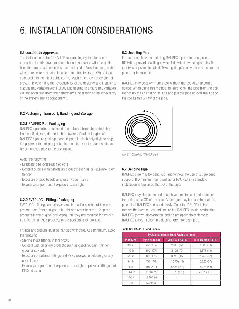
6.3 Uncoiling PipeForbestresultswheninstallingRAUPEXpipefromacoil,useaREHAUapproveduncoilingdevice.Thiswillallowthepipetolayflat(nottwisted)wheninstalled.Twistingthepipemayplacestressonthepipeafterinstallation.
RAUPEXmaybetakenfromacoilwithouttheuseofanuncoilingdevice.Whenusingthismethod,besuretorollthepipefromthecoil.Donotlaythecoilflatonitssideandpullthepipeupoverthesideofthecoilasthiswilltwistthepipe.
Fig. 6.1: Uncoiling RAUPEX pipe
6.4 Bending PipeRAUPEXpipemaybebent,withandwithouttheuseofapipebendsupport.TheminimumbendradiusforRAUPEXinastandardinstallationisfivetimestheODofthepipe.
RAUPEXmayalsobeheatedtoachieveaminimumbendradiusofthreetimestheODofthepipe.Aheatgunmaybeusedtoheatthepipe.HeatRAUPEXandbendslowly.OncetheRAUPEXisbent,removetheheatsourceandsecuretheRAUPEX.AvoidoverheatingRAUPEX(browndiscoloration)anddonotapplydirectflametoRAUPEXtoheatit(fromasolderingtorch,forexample).
Table 6.1: RAUPEX Bend Radius
Typical Minimum Bend Radius in (mm)
Pipe Size Typical 8X OD Min. Cold 5X OD Min. Heated 3X OD
3/8in 4.0(102) 2.500(64) 1.500(38)
1/2in 5.0(127) 3.125(79) 1.875(48)
5/8in 6.0(152) 3.750(95) 2.250(57)
3/4in 7.0(178) 4.375(111) 2.625(67)
1 in 9.0(229) 5.625(143) 3.375(86)
11/4in 11.0(279) 6.875(175) 4.125(105)
11/2in 13.0(330) -- --
2 in 17.0(432) -- --
26

Bend Radius90
Fig. 6.2: Bend radius of RAUPEX pipe
6.5 Distance Between Fittings AminimumdistancebetweenEVERLOC+fittingsisrequiredtoensurethefittingsarenotdamagedduringtheexpansionprocessbytheinstallationtools.Aminimumpipelengthof3timesthelengthofsleeveisrequiredbetweenfittingsforproperinstallation.
A3A
EVERLOC+ PEXaCompression Sleeve
RAUPEX Pipe
EVERLOC+ Fitting
Fig. 6.3: Required minimum distance between fittings
6.6 Pipe ProtectionPlacepipeprotectionaroundRAUPEXpipetopreventabrasionwhenpassingthroughthebuilding'sframework.
WhenRAUPEXpipepassesthroughstuds,walls,floorplates,joistsandotherstructuralmembers,caremustbetakennottodamagethepipe.
Protectionisnotrequiredforinstallationinwoodstuds,walls,floorplatesorjoistsifthefollowingprovisionsaremet: - Theholeisatleast1/4in(6mm)largerthantheoutsidediameter(OD)ofthepipe-Thepipeisfreetomoveduringexpansionandcontraction-Theholeisclean(e.g.,freeofsplinters,burrsandroughedges)-Theholeissupportingonlytheweightofthepipe(withfluid),andnotamechanicaldevice
-Theholehassmooth,non-abrasiveinteriorsurface(e.g.,bushing)-Prevailinglocalcodesallowsuchpractice
UseofPEprotectionsleeveorotherapprovedsupportdeviceisrequiredforRAUPEXpipewhenpassingthroughholesinsteel,concreteormasonrywalls,joistsandotherstructuralmembers.
WhenRAUPEXpiperunsthroughanyabrasivematerial,oraholethatdoesnotallowfreemovement,itmustbeprotectedbyPEprotectionsleeveoranotherapprovedinstallationaccessory,suchassuspensionclampsorisolators.
Fig. 6.4: Isolation suspension clamps Fig. 6.5: Pipe isolator
Fig. 6.6: PE protection sleeve
RAUPEXpipeisrecommendedforinstallationdirectlywithinorbelowaconcreteslab.TheuseofPEprotectionsleeveorPVCbendguidesatslabpenetrationsisrecommended.
Fig. 6.7: Slab penetration
27
6.7 InsulationThermalconductivityofRAUPEXpipeismuchlowerthanthatofmetallicpipes.Insulationcanbeinstalledtofurtherenhancethisproperty,todecreaseenergyusage,andmaintainwatertemperatureinsidethepipe.BecauseofthethermalpropertiesofRAUPEXpipe,itisalsolesssusceptibletocondensationorsweatingoncoldwaterlines.
Insulationcanbeinstalledoncoldwaterlinestoimproveresistancetocondensationorbettermaintaininternalwatertemperature.Itisalsorecommendedtoinsulatepipinginunconditionedspacesandhighmoistureareas.Alwayscomplywithprevailinglocalcodes.
6.8 Installation Below-grade, in-slabRAUPEXmaybeinstalleddirectlywithinorbelowaconcreteslab.Thisisespeciallyusefulinslab-on-gradeconstruction.RAUPEXpipesencasedwithinconcreteslabsarenotrequiredtobesleeved.
ToprotectRAUPEXpipefromabrasionwhereitpassesthroughtheconcrete,theuseofPEprotectionsleevesorPVCbendguidesatallslabpenetrationsisrecommended.
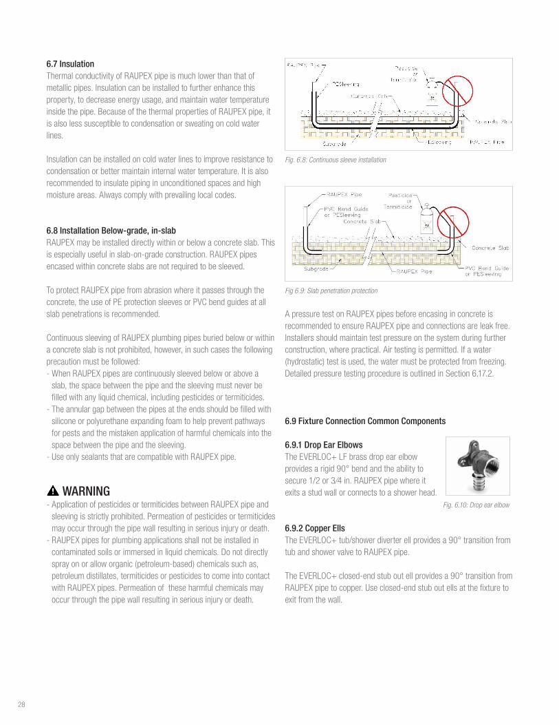
ContinuoussleevingofRAUPEXplumbingpipesburiedbeloworwithinaconcreteslabisnotprohibited,however,insuchcasesthefollowingprecautionmustbefollowed: - WhenRAUPEXpipesarecontinuouslysleevedbeloworaboveaslab,thespacebetweenthepipeandthesleevingmustneverbefilledwithanyliquidchemical,includingpesticidesortermiticides. - Theannulargapbetweenthepipesattheendsshouldbefilledwithsiliconeorpolyurethaneexpandingfoamtohelppreventpathwaysforpestsandthemistakenapplicationofharmfulchemicalsintothespacebetweenthepipeandthesleeving. - UseonlysealantsthatarecompatiblewithRAUPEXpipe.
WARNING - ApplicationofpesticidesortermiticidesbetweenRAUPEXpipeandsleevingisstrictlyprohibited.Permeationofpesticidesortermiticidesmayoccurthroughthepipewallresultinginseriousinjuryordeath. - RAUPEXpipesforplumbingapplicationsshallnotbeinstalledincontaminatedsoilsorimmersedinliquidchemicals.Donotdirectlysprayonoralloworganic(petroleum-based)chemicalssuchas,petroleumdistillates,termiticidesorpesticidestocomeintocontactwithRAUPEXpipes.Permeationoftheseharmfulchemicalsmayoccurthroughthepipewallresultinginseriousinjuryordeath.
Fig. 6.8: Continuous sleeve installation
Fig 6.9: Slab penetration protection
ApressuretestonRAUPEXpipesbeforeencasinginconcreteisrecommendedtoensureRAUPEXpipeandconnectionsareleakfree.Installersshouldmaintaintestpressureonthesystemduringfurtherconstruction,wherepractical.Airtestingispermitted.Ifawater(hydrostatic)testisused,thewatermustbeprotectedfromfreezing.DetailedpressuretestingprocedureisoutlinedinSection6.17.2.
6.9 Fixture Connection Common Components
6.9.1 Drop Ear ElbowsTheEVERLOC+LFbrassdropearelbowprovidesarigid90°bendandtheabilitytosecure1/2or3⁄4in.RAUPEXpipewhereitexitsastudwallorconnectstoashowerhead. Fig. 6.10: Drop ear elbow
6.9.2 Copper Ells TheEVERLOC+tub/showerdiverterellprovidesa90°transitionfromtubandshowervalvetoRAUPEXpipe.
TheEVERLOC+closed-endstuboutellprovidesa90°transitionfromRAUPEXpipetocopper.Useclosed-endstuboutellsatthefixturetoexitfromthewall.
28
TheEVERLOC+straightcopperstubsprovideatransitionfromRAUPEXpipetocopper.Useclosed-endstuboutellsatthefixturetoexitfromthewall.
Fig. 6.11: EVERLOC+ copper ells
6.9.3 EVERLOC+ ValvesEVERLOC+straightandanglestopvalvesareintendedforusewithpoint-of-usefixtures.
BecauseRAUPEXpipehasthesameoutsidediameterasstandardcopperpipe,youcanusestandardcompressionstraightandanglestopvalveswithstiffenerstoconnecttoRAUPEXpipe.
Fig. 6.12: EVERLOC+ Valves
6.9.4 Other EVERLOC+ Transition FittingsREHAUalsooffersfollowingconnectiontypesfortheEVERLOC+fittingswhenmakingconnectionstofixtures.RefertotheREHAU Sustainable Building Technology Catalogforacompletearticlelisting.
- EVERLOC+90°Elbows,PEXtoCopper(CMaleandCFemale) - EVERLOC+Adapters,PEXtoCopper(CMaleandCFemale) - EVERLOC+MPTAdapters,PEXtoMPT - EVERLOC+FPTAdapters,PEXtoFPT - EVERLOC+LFBrassSwivelAdapters,PEXtoNPS
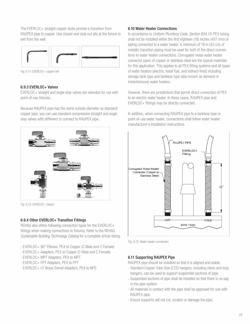
6.10 Water Heater Connections In accordance to Uniform Plumbing Code, Section 604.13:PEXtubingshallnotbeinstalledwithinthefirsteighteen(18)inches(457mm)ofpipingconnectedtoawaterheater.Aminimumof18in(45cm)ofmetallictransitionpipingmustbeusedforbothofthedirectconnec-tionstowaterheaterconnections.Corrugatedmetalwaterheaterconnectorpipesofcopperorstainlesssteelarethetypicalmaterialsforthisapplication.ThisappliestoallPEXfittingsystemsandalltypesofwaterheaters(electric,fossilfuel,andindirect-fired)includingstoragetanktypeandtanklesstype(alsoknownasdemandorinstantaneous)waterheaters.
However,therearejurisdictionsthatpermitdirectconnectionofPEXtoanelectricwaterheater.Inthesecases,RAUPEXpipeandEVERLOC+fittingsmaybedirectlyconnected.
Inaddition,whenconnectingRAUPEXpipetoatanklesstypeorpoint-of-usewaterheater,connectionsshallfollowwaterheatermanufacturer’sinstallationinstructions.
Fig. 6.13: Water heater connection
6.11 Supporting RAUPEX PipeRAUPEXpipeshouldbeinstalledsothatitisalignedandstable. - StandardCopperTubeSize(CTS)hangers,includingclevisandloophangers,canbeusedtosupportsuspendedsectionsofpipe. - Suspendedsectionsofpipeshallbeinstalledsothatthereisnosaginthepipesystem. - AllmaterialsincontactwiththepipeshallbeapprovedforusewithRAUPEXpipe. - Ensuresupportswillnotcut,scratchordamagethepipe.
29

- Suspendedinstallationsinwood-frameconstructioncanutilizestrutchannelhangingwithall-threadasthesupportdevicewiththeappropriateclampstosecurepipetothestrut.Whenclampingpipe,besurenottodeformthepipewiththeforceoftheclamp. - Installationsinsteel-frameconstructioncanbedonesimilarly,butcanalsousebeamclampstosecuretheall-threadtosteelI-Beams. - Steeljoistspacecanbeusedasthesupportmethod.
Whennotinstallinginsuspension,othersupportmechanismsforRAUPEXpipecanbeused.Theseincludesinglenailhooks,pipesupportbends,talondrivehooksandlockingclips.Thesecanalsobeusedforsmallerbranchrunsofpipeaswellastoassistinmakingbendstoconnecttofixtures.
RAUPEXpipe3/8to1in.diametermustbesupportedwithamaximumspacingof32in(80cm)horizontallyand10ft(3m)vertically.RAUPEXpipelargerthan1in.diametermustbesupportedwithamaximumspacingof48in(120cm)horizontallyand10ft(3m)vertically.Alwayscomplywiththeprevailinglocalcodeforsupportspacingintervals.
Fig. 6.14: Single nail hooks Fig. 6.15: Pipe support bend
Fig. 6.16: Talon drive hooks Fig 6.17: Locking clip
6.11.1 Galvanized Steel Support ChannelREHAUgalvanizedsteelsupportchannelisdesignedtosupportRAUPEXpipe,minimizespipeexpansionandreducestheamountofCTSsupports.TheprofileofthegalvanizedsupportchannelisdesignedsotheRAUPEXpipewillsnapinwithoutrequiringadditionalfasteningmethodstoholdthepipeinplace.
Thesupportchannelcanbecuttomeetinstallationrequirementsusingpowertoolssuchasabandsaworhandtools.Whencutting,besurenottobendoraltertheoverallprofileofthechannel.Aftercuttingthechannel,besuretoremoveanysharpedgesorburrstopreventdamagetotheRAUPEXpipe.
Typicalmechanicalclevishangerscanbeusedforsupport,andtheslimprofileofthechannelallowsstandardCTSinsulationtobeinstalledaroundit.InstallingRAUPEXpipeintothesupportchannelbeforesuspendingtheassemblyisrecommended.Iffittingswillneedtobeinstalledin-linewiththerunofpipeinthesupportchannel,besuretohavetheRAUPEXpipeoverhangtheendofthesupportchannelatleasttwoEVERLOC+sleevelengths.Additionally,thegalvanizedsteelsupportchannelshallextendaminimumof1in.(2.5cm)pastthehanger.
Use3/8in.threadedrodtosuspendthesupportchannelwithamaximumspacingbetweensupportsof8ft(2.4m).Alwayscomplywithprevailinglocalcodesforsupportspacingintervals.
Fig. 6.18: RAUPEX pipe supported with steel support channel
6.12 Supporting EVERLOC+ FittingsSupportsandclampsshallnotbeplaceddirectlyontheEVERLOC+fitting,multi-portteeorcompressionsleeve.Alwayscomplywithprevailinglocalcodes.
6.13 Copper SolderingPropersolderingtechniquesmustbefollowedwhensolderingallcompression-sleevefittingsaccordingtotheCopperDevelopmentAssociation(CDA)Handbook:-Thesurfaceofthefittingsolderingareamustbeproperlycleanedforagoodsolderconnection.Applyingfluxisnotconsideredsufficientcleaningforthesolderingarea.Usingapropersandingorbrushtechniqueisnecessarytoremovethesurfaceoxides.Inordertopreventfurtherformationofoxides,thefluxshouldbeappliedimmediatelyafterthecleaningprocess.Aproperfluxthatiscompatiblewiththebrassalloymustbeused.
30

-Caremustbetakentonotoverheatthesolderingsurfaceasthiscanleadtotheformationofoxidespreventinggoodadhesionofthesoldermaterial.Itisimperativethatthefittingisheatedevenlyaroundtheentiresurfacesoastonotoverheatoneparticulararea.-Allcompletedsolderjointsmustbetestedforjointintegrityfollowingtheproceduresprescribedbyprevailinglocalcodes.
WhensolderinganEVERLOC+LFbrassfitting:-Thefittingmustbesolderedontothecopperfirst.-Thesolderjointmustbeallowedtocooltoambientroomtempera-turepriortomakinganEVERLOC+connection.
Fig. 6.19: Solder prior to making EVERLOC+ connection
Fig. 6.20: Never solder after EVERLOC+ connection has been made
WARNING Useglovesandaholdingtool.Heatedpipeandfittingscancauseburns.
6.14 Kink RepairRAUPEXpipeisflexibleandresistskinkingevenattemperatureswellbelowfreezing.Ifthepipedoesbecomekinked,flowmaybeobstructedorreduced.Kinkedpipemustberepaired.
Straightenthepipebyheatingtheareawithaheatgun,rotatingtheheatgunaroundthepipetoevenlyheatthesurface.Alwaysusecautionwhenoperatingaheatgunandneveruseatorchoropenflametoheatthepipe.
Whenfullyheated,thepipewillbecometransparent.Whenthekinkisgone,turnofftheheatgunandlettheareacool.(Itisnormalforsmallbubblesorwrinklestoappear.)Thistypeofheatingwillannealorstiffenthepipe,makingitstrongerbutalsolessflexibleintheheatedarea.Therefore,donottrytobendthepipeinthesamespot.Thismayrequireaslightadjustmentoffasteners.
6.15 Thawing Frozen PipeWhenconditionsoccurthatallowwatertofreezeinsidethepipe,theflexibilityofRAUPEXallowsthepipetoexpandaswaterfreezes,aslongasthepipehasroomtoexpand.
Whenthewaterthaws,thepipereturnstoitsoriginalshape.Ifthepipeisnotallowedtoexpand(e.g.,itisencasedinconcrete),itmayburst.Iffreezingdoesoccur,thefollowingmethodscanbeusedtothawthefrozensection: - Heatthefrozenareawithaheatgun.Besurenottoconcentrateexcessiveheatinasingleareafortoolong - Wraptowelsaroundthepipingandpourhotwateronthetowels - Useaspaceheatertowarmtheroomuntilthefrozensectionthaws
WhiletheflexibilityoftheRAUPEXpipeallowsittoexpandaswaterfreezesinthepipe,thisflexibilitydoesnotensuretheintegrityofthejoint.Installersmusttakeprecautionstoensurethatpipesandfittingsdonotfreeze.Thismayresultinleaksandoperationalfailures.
6.16 DisinfectionDisinfectionofthesystemshouldalwaysfollowprevailinglocalcodesandrequirements.Ifrequiredbycodeandnoconditionsarespecified,disinfectusingchlorinationaccordingtoAWWAorICCproceduresoutlinedbelow:
Table 6.2: AWWA/ICC Disinfection Schedule
Chlorine Concentration Disinfection Period Authority
50to100ppm 3hours AWWA
50ppm 6hours ICC
Pre-mixsolutionbeforeinjectingintosystem.Donotallowdisinfectionsolutiontositinsystembeyondthedisinfectionperiod.Thoroughlyflushentiresystemwithpotablewaterafterdisinfection.
31

6.17 Pressure TestingRAUPEXpipingsystemsmustbepressuretestedinaccordancewithprevailinglocalcoderequirements.
WARNING Failuretofollowthepropersafetyprecautionsforanairpressuretestcouldresultindangerousseparationofthematerial,leadingtoseriousinjuryordeath.
NOTICE - AlwaysrefertotheprevailinglocalcodesforpressuretestingrequirementsanduseairtestingonlyifapprovedbythelocalAuthorityHavingJurisdiction(AHJ). - REHAUonlyprovidesthegeneralguidelinesforperformingapressuretest,whichbynomeanssupersedeorareintendedtocontradictsafetyrequirements.Itistheresponsibilityoftheinstallingcontractortoensureaproperandsafepressuretestisperformedonsite.
Thefollowingrecommendedpressuretestprocedureappliestobothcompressedairandhydrostatic(water)testing:
6.17.1 General Recommendations-Apressuretestmustalwaysbeperformedpriortoclosinginthesystem(e.g.,behinddrywall).-Performtestusingwaterorairatambienttemperature.Donotexceed150psi(1030kPa)forthepipingsystem.Verifymaximumpressurelimitsarenotexceededforallsystemcomponentspriortoperformingthepressuretest.-WhenairpressuretestingwithEVERLOC+polymerfittingsdonotexceed120psi(825kPa).SeeSection6.17.3SafetyConsiderations.-ApressuretestmustalwaysbeperformedonthesystempriortoandduringtheinstallationofaconcreteslabtoensurethatRAUPEXpipeandconnectionsareleakfree.-Testsshallcomplywithprevailinglocalcodes,and,whererequired,shallbewitnessedbythebuildingofficial.
6.17.2 REHAU Pressure Test Procedure-Useanairtestifconditionsdonotpermitawatertest(e.g.,freezingconditions,insufficientwatersupply/pressure).-Airtemperaturewillaffectthegaugepressure,soperformallpressuretestsataconstanttemperature.Verifymaximumpressurerequirementsforothersystemspriortoperformingthetest.-Performapreliminarypressuretestpressurizingthesystemto1.5timesthemaximumoperatingpressure,nottoexceedthemaximumpressuresdefinedabove,for30minutes.-Asthepipingexpands,restorepressure,firstat10minutesintothetestandagainat20minutes.
-Attheendofthe30-minutepreliminarytest,pressuremustnotfallbymorethan5psifromthemaximum,andthereshallbenoleakage.-Afterperformingthepreliminarytest,performthemainpressuretestimmediately.Themainpressuretestshalllastatleast2hours.Thetestpressureshallberestoredandmustnotfallmorethan3psiafter2hours.Noleakageshouldbedetected.-Itisrecommendedtomaintaintestpressureonthesystemduringfurtherconstruction,wherepractical,toimmediatelyidentifyanydamage.Ifawater(hydrostatic)testisused,protectthewaterfromfreezingordrainwaterfrompipes.
6.17.3 Safety ConsiderationsInmanycircumstances,performingthepressuretestwithairistheonlypracticalmethodfortheinstallingcontractor.Compressedaircanstoreahighamountofenergyascomparedtoperformingthepressuretestwithwater.Therefore,itistheresponsibilityoftheinstallingcontractortofollowallsafetyprecautionsandfollowallgeneralinstallationpractices.
Ifathermosetpolymer(e.g.,PEXpipe)isover-pressurizedandfails(bursts),itdoessoinaductilemode,meaningthatthepipewillswellandthensplitwithnoseparationoffragments.TheminimumburstratingoftheREHAUPEXapipeis480psi(3310kPa)at73.4°F(23°C).
Ifarigidthermoplasticpolymer(e.g.,PPSU)materialisover-pressur-izedandfails(bursts),itdoessoinabrittlemodeandcanresultinseparationofthematerial.
Thereforewhentestingwithcompressedair,thefollowingprecautionsmustbetaken: - Whenotherthermoplasticpipingmaterials(e.g.,CPVC,PP-R)arepresentinthepipingsystem,thesesectionsofpipingmustbeisolatedfromtheREHAUPEXapipingsystemduringthepressuretest.Theinstallermustconsulttheotherpipemanufacturer’sinstallationinstructionsforpressuretestingthosesectionsofthesystem.-Conductavisualinspectionofthepipingsystem,toensureallconnectionshavebeenproperlymadeandallpipinghasbeenproperly secured prior to pressurization.-Allpersonnelperformingthepressuretestmustbeproperlytrainedandweartheappropriatepersonalprotectiveequipment(PPE).-Onlythequalifiedpersonnelshouldbepresentforthepressuretest-Allothertradesmustbenotifiedthatthepressuretestwillbeconductedonthepipingsystem.
32

33

Forupdatestothispublication,visitna.rehau.com/resourcecenterTheinformationcontainedhereinisbelievedtobereliable,butnorepresentations,guaranteesorwarrantiesofanykindaremadeastoitsaccuracy,suitabilityforparticularapplicationsortheresultstobeobtainedtherefrom.Beforeusing,theuserwilldeterminesuitabilityoftheinformationforuser’sintendeduseandshallassumeallriskandliabilityinconnectiontherewith.©2018REHAU 855.73904.2018


