16
PFIFFN Transfo NER Instrument ormers Pvt. Ltd. 178/2, Sarul, Nashik – 422 010, INDIA

PFIFFNER InstrumentTransformers Pvt. Ltd.
178/2, Sarul,Nashik – 422 010,
INDIA
PFIFFNER InstrumentTransformers Pvt. Ltd.
178/2, Sarul,Nashik – 422 010,
INDIA
PFIFFNER InstrumentTransformers Pvt. Ltd.
178/2, Sarul,Nashik – 422 010,
INDIA
PFIFFNER Instrument Transformers Pvt. Ltd.176,178/2, Sarul , Nashik – 422 010, INDIA
PFIFFNER Instrument Transformers Pvt. Ltd.176,178/2, Sarul , Nashik – 422 010, INDIA
PFIFFNER Instrument Transformers Pvt. Ltd.176,178/2, Sarul , Nashik – 422 010, INDIA

Outdoor operation
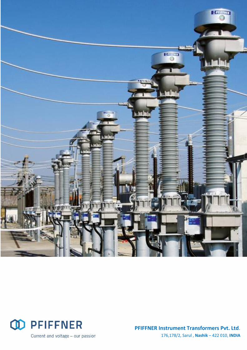
72 kV - 420kVCurrent Transformers
72 kV - 245 kVInductive Voltage Transformers
72 kV – 800 kVCapacitive Voltage Transformers
Oil-paper Insulated Fine-graded Bushing Generously-sized Terminal Box Robust design Earthquake-resistant
Oil-paper Insulated Fine-graded Bushing Oil Level Indicator Generously-sized Terminal Box Robust design Earthquake-resistant Low center of gravity
Upgradable for the transmissionof high-frequency signals
No on-site adjustments isnecessary
Increased security againstrelaxation oscillation
The high voltage oil-filled CT’s consist
of head types with metal expansion
bellows to withstand higher thermal
loads. The CT’s can be produced with
flat or round primary connectors
Our VT’s are working at low induction.
With an open delta winding and damping
unit, ferroresonance can be minimized if
requested. The secondary terminal box
can be equipped with fuses to protect
the secondary wiring and equipment
All CVT’s are ferro-resonance free and
are not damaged by line discharge.
Optionally all CVT’s can be equipped
with line trap connections and PLC
assessories.The secondary terminal
box can be equipped with fuses
Swiss Quality combined with Global Experience
Outdoor operation
72 kV - 420kVCurrent Transformers
72 kV - 245 kVInductive Voltage Transformers
72 kV – 800 kVCapacitive Voltage Transformers
Oil-paper Insulated Fine-graded Bushing Generously-sized Terminal Box Robust design Earthquake-resistant
Oil-paper Insulated Fine-graded Bushing Oil Level Indicator Generously-sized Terminal Box Robust design Earthquake-resistant Low center of gravity
Upgradable for the transmissionof high-frequency signals
No on-site adjustments isnecessary
Increased security againstrelaxation oscillation
The high voltage oil-filled CT’s consist
of head types with metal expansion
bellows to withstand higher thermal
loads. The CT’s can be produced with
flat or round primary connectors
Our VT’s are working at low induction.
With an open delta winding and damping
unit, ferroresonance can be minimized if
requested. The secondary terminal box
can be equipped with fuses to protect
the secondary wiring and equipment
All CVT’s are ferro-resonance free and
are not damaged by line discharge.
Optionally all CVT’s can be equipped
with line trap connections and PLC
assessories.The secondary terminal
box can be equipped with fuses
Swiss Quality combined with Global Experience

Technical Data – Current Transformers
Type 145 kV 245 kV 420 kVUnit height A (mm) 2895 3770 5320Primary terminal to base height B (mm) 2160 3017 4375Mounting distance C (mm) 450 x 450 450 x 450 600 x 600Base outside dimension D (mm) 504 504 700Base outside dimension D1 (mm) 511 511 650Unit including terminal box E (mm) 720 720 855Min. creepage distance (mm) 3625 6125 10500Approximate weight (kg) 450 820 1465
Type 145 kV 245 kV 420 kVStandard IEC 61869 , IS 16227Highest voltage for equipment kV 145 245 420Rated power frequency withstand voltage kV 275 460 630Rated lightning impulse withstand voltage kVp 650 1050 1425Rated Switching Impulse withstand voltage kVp - - 1050Frequency Hz 50/60Primary rated current A 50- 5000Secondary rated current A 1/5Rated short time thermal current kA/1s ≤ 69Rated dynamic current kAp ≤ 175Accuracy Class 0.2,0.2S; 0.5; 5P,PX, TPXMaximum number of cores per CT 6

Technical Data – Inductive Voltage Transformers
Type 72 kV 145 kV 245 kVUnit height A (mm) 1840 2735 3720Base to Upper Tank B (mm) 665 595 940Mounting distance C (mm) 500 x 500 500 x 500 600 x 600Base outside dimension D (mm) 600 600 700Unit including terminal box E (mm) 820 860 970Min. creepage distance (mm) 1815 3625 6125Approximate weight (kg) 350 425 850
Type 72 kV 145 kV 245 kVStandard IEC 61869 , IS 16227Highest voltage for equipment kV 72.5 145 245Rated Secondary Voltage V 100,100/√3, 110, 110/√3 , 115 , 115/√3Rated power frequency withstand voltage kV 140 275 460Rated lightning impulse withstand voltage kVp 325 650 1050Frequency Hz 50 / 60Max. simultaneous burden VA 150 200 300Accuracy Class 0.2; 0.5; 3PNumber of windings 3

Technical Data – Capacitive Voltage Transformers
Type 72 kV 170 kV 245 kV 300 kV 420 kVUnit height A (mm) 1840 2435 3010 3625 4055Mounting distance (mm) 450 450 450 450 450Min. creepage distance (mm) 1815 4250 6125 7500 10500Approximate weight (kg) 320 365 510 450 620
Type 72 kV 170 kV 245 kV 300 kV 420 kVStandard IEC 61869 , IS 16227Highest voltage for equipment kV 72.5 145 245 300 420Rated Secondary Voltage V 100,100/√3, 110, 110/√3 , 115 , 115/√3Rated Capacitance pF 3000 - 10000Rated power frequency withstand voltage kV 140 275 460 460 630Rated lightning impulse withstand voltage kVp 325 650 1050 1050 1425Frequency Hz 50/60Max. simultaneous burden VA 100 100 150 200 200Accuracy Class 0.2; 0.5; 3PNumber of windings 3

Technical Data – Resistive Capacitive Voltage Divider
72 – 362 kV 420 – 550 kVType 72 123 145 170 245 300 362 420 550Standard DIN / IEC / IEEEHighest voltage for equipment (Um) kV 72.5 123 145 170 245 300 362 420 550Rated power-frequency withstandvoltage
kV 140 230 275 325 460 460 510 630 680
Rated lightning impulse withstandvoltage
kV 325 550 650 750105
01050 1175 1425 1550
Rated frequency Hz DC/16.7 / 50 / 60Accuracy class 0.1; 0.2; 0.5; 1.0; 3.0Frequency bandwidth DC / 15 – 10000 (30000)Burden type kV R or R // CBurden range ≥ 100 kΩRated voltage factors 1.5 – 30 sec / 1.9 – 30 sec / 1.9 – 8 hTemperature range °C -50... +40
Type 72 123 145 170 245 300 362 420 550
Total height of unit* Amm 1326 1626 1826 2026 2626 2869 3511 3911 4669
Height to primary terminal* Bmm 1186 1486 1686 1886 2486 2729 3371 3771 4529
Depth of unit includingterminal box
Cmm 724 724 724 724 724 724 724 724 724
Depth of unit base Dmm 500 500 500 500 500 500 500 500 500
Width of unit base Emm 500 500 500 500 500 500 500 500 500
Distance between screw holesat base
Fmm 450 450 450 450 450 450 450 450 450
Min. creepage distance* mm 2420 3540 4280 5030 7260 7900 9390 12280 14950
Approximate weight* kg 90 100 110 130 150 170 190 210 230

General Arrangement – 245 kV Current Transformer
Standard IS61227-2, IEC61869-2
Voltage Level 245 kV /460 kV rms /1050 kVp
Frequency 50 Hz
Icth 120%
Ith 40 kA for 1 sec
Core 1 800-1600 / 1A; PS
Core 2 800-1600 / 1A ;PS
Core 3 800-1600 / 1A ;0.2S; 20VA
Core 4 800-1600 / 1A; PS
Core 5 800-1600 / 1A; PS
Primary Terminal Flat, DIN F2, Horizontal
Creepage Distance 31 mm/kV
Ratio change over By secondary
Total Weight 820 kg ±10%
Oil Weight 210 kg ±10%
Exhibit 1

General Arrangement – 245 kV Inductive Voltage Transformer
Standard IEC61869-1 & IEC61869-3
Voltage Class 245 kV
Insulation Level 460 kVrms /1050 kVp
Frequency 50 Hz
Voltage Class 245 kV
Voltage Factor 1.2 cont. / 1.5 for 30 sec.
Insulation Level 460 kV rms /1050kVp
Winding 1 110/ √3 V, 50 VA, 3P
Winding 2 110/ √3 V ,50 VA ,3P
Winding 3 110/ √3 V ,50 VA, 0.2
Primary Terminal Flat, DIN F2, horizontal
Creepage Distance 31 mm/kV
Total Weight 850 kg. ±10%
Oil Weight 185 kg. ±10%
Exhibit 2

General Arrangement – 300 kV Capacitive Voltage Transformers
Standard IEC 61869-1 & IEC 61869-5
Frequency 50 Hz
Voltage Class 300 kV
Total ThermalOutput
300 VA
Insulation level 460 kVrms / 1050 kVp
Voltage factor 1.2 CONT. / 1.5-30 sec.
Equivalentcapacitance
4400 pF (+10%, -5%)
Volts A-NHF 275000 / √3
Winding 1 110 / √3, 3P, 50 VA
Winding 2 110 / √3, 3P, 50 VA
Winding 3 110 / √3, 0.2 , 50 VA
Creepage Distance 25 mm / kV
Total Weight 390 kg ±10%
EMU oil weight 65 kg ±10%
Capacitor oil weight 40 kg ±10%
Exhibit 3
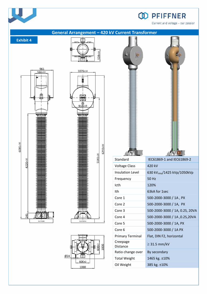
General Arrangement – 420 kV Current Transformer
Standard IEC61869-1 and IEC61869-2
Voltage Class 420 kV
Insulation Level 630 kVrms/1425 kVp/1050kVp
Frequency 50 Hz
Icth 120%
Ith 63kA for 1sec
Core 1 500-2000-3000 / 1A , PX
Core 2 500-2000-3000 / 1A, PX
Core 3 500-2000-3000 / 1A, 0.2S, 20VA
Core 4 500-2000-3000 / 1A ,0.2S,20VA
Core 5 500-2000-3000 / 1A, PX
Core 6 500-2000-3000 / 1A PX
Primary Terminal Flat, DIN F2, horizontal
CreepageDistance 31.5 mm/kV
Ratio change over By secondary
Total Weight 1465 kg. ±10%
Oil Weight 385 kg. ±10%
Exhibit 4

Cross Section – OIP Current Transformer
1. Bellow Cover
2. Stainless Steel Bellows / Oil LevelIndicator
3. Cores with Secondary Winding
4. Core Box
5. Primary Assembly
6. Primary Terminal
7. Aluminium Tank
8. Fine graded Insulation
9. Porcelain / Composite Insulator
10. Aluminium Base
11. Oil Sampling Valve
12. Tan Delta measuring tap
13. Terminal Box
14. Secondary Lead out
8
9
14
13
11
10
12
7
6
3
2
1
4
5

Cross Section – OIP Inductive Voltage Transformer
1. Bellow Cover
2. Stainless Steel Bellows / Oil LevelIndicator
3. HV Terminal
4. Porcelain / Composite Insulator
5. Fine graded Insulation
6. Aluminium Tank
7. Interleaved Core
8. Oil Sampling Valve
9. HV Shield
10. Secondary Lead out
11. Terminal Box
1
2
4
3
5
6
7
9
10
11]1 8

Cross Section – OIP Capacitive Voltage Transformer
1. HV Terminal
2. Stainless Steel Bellows
3. Porcelain / Composite Insulator
4. Capacitor Divider
5. M.V. Tap Terminal
6. Core Coil Assembly
7. Oil Sampling Valve
8. Aluminium EMU Tank
9. Terminal Box
10. Inductor Assembly
11. Damping Resistor
1
2
3
58
96
711
10
4

Germany, Itzehoe
Turkey Ankara
India, Nashik
Brazil, Itajai
Instrument Transformers HV SF6 AIS/GIS
Instrument Transformers HV Oil/ MV resin
Instrument Transformers HV Oil
Instrument Transformers HV Oil
www.pfiffner-group.com
Local manufacturing close to our customers
SwitzerlandHirschthal : Instrument Transformers HV Oil & SF6, MV&LV
Kaiseraugst : Busbar solutions, bushings
Nidau : Disconnectors, cable solutions rolling stock
Basel : AC and DC Test systems, Instrumentation

Global presence
PFIFFNER Instrument Transformers Ltd5042 HirschthalSwitzerland
+41 (0)62 [email protected]/pch
PFIFFNER Systems Ltd4303 KaiseraugstSwitzerland
+41 (0)61 [email protected]
PFIFFNER Deutschland GmbH25524 ItzehoeGermany
+49 (0)48 [email protected]/pde
PFIFFNER Transformatör A.S.06750 Akyurt /AnkaraTurkey
+90 (0)31 [email protected]/ptr
PFIFFNER do Brasil Ltda88307-740 ItajaíBrazil
+55 (0)47 [email protected]/pbr
PFIFFNER Instr. Transf. Private Ltd178/2, Sarul, NashikIndia
+91 253 297 [email protected]
MGC Moser-Glaser Ltd4303 KaiseraugstSwitzerland
+41 (0)61 [email protected]
ALPHA Elektrotechnik Ltd2560 NidauSwitzerland
+41 (0)32 [email protected]
HAEFELY Ltd4052 BaselSwitzerland
+41 (0)61 373 41 [email protected]
This document has been drawn up with the utmost care. We cannot, however, guarantee that it is entirely complete, correct or up-to-date.Copyright PFIFFNER – Subject to change without notice 01.2020
PFIFFNER Instrument Transformers Pvt. Ltd.176,178/2, Sarul ,Nashik – 422 010, INDIA


