18
PFMS User Manual Page | 0 NuVue Therapeutics, Inc. User’s Manual Pulse Flow Microencapsulation System Unit II
| Date post: | 17-Jan-2017 |
| Category: |
Documents |
| Upload: | james-lockwood |
| View: | 134 times |
| Download: | 2 times |
PFMS User Manual
Page | 0 NuVue Therapeutics, Inc.
User’s Manual
Pulse Flow Microencapsulation System
Unit II

PFMS User Manual
Page | 1 NuVue Therapeutics, Inc.
2016 NuVue Therapeutics, Inc.
Table of Contents TABLE OF CONTENTS .............................................................................................................................................. 1
FUNCTIONAL DESCRIPTION .................................................................................................................................... 3
OVERVIEW .................................................................................................................................................................... 3 MECHANISM ................................................................................................................................................................. 3 SOFTWARE FUNCTION ..................................................................................................................................................... 3
PROCESS FLOW DIAGRAM ..................................................................................................................................... 4
PARTS LIST ............................................................................................................................................................. 5
HARDWARE SETUP GUIDE ..................................................................................................................................... 6
OVERVIEW .................................................................................................................................................................... 6 HARDWARE INSTALLATION ............................................................................................................................................... 6 SOFTWARE SET-UP ......................................................................................................................................................... 6 SYRINGE PUMP OPERATION TESTS ..................................................................................................................................... 6 VIBRATION HEAD OPERATION TESTS .................................................................................................................................. 6 ELECTROSTATIC CHARGE OPERATION TESTS ......................................................................................................................... 7
PRE-BATCH RUN CHECKLIST ................................................................................................................................... 8
OVERVIEW .................................................................................................................................................................... 8 CHECKLIST .................................................................................................................................................................... 8
BATCH RUN PROCEDURE ....................................................................................................................................... 9
OVERVIEW .................................................................................................................................................................... 9 PRIME CORE TUBING ...................................................................................................................................................... 9 PRIME SHELL TUBING ...................................................................................................................................................... 9 PREPARE CORE NOZZLE ................................................................................................................................................... 9 SET UP DROPLET CHAIN ................................................................................................................................................... 9 BEGIN BATCH .............................................................................................................................................................. 10 BEGIN COLLECTION ....................................................................................................................................................... 10 STOP COLLECTION ........................................................................................................................................................ 10
BATCH RECORD .................................................................................................................................................... 11
SHUTDOWN AND CLEANUP PROCEDURES ........................................................................................................... 13
OVERVIEW .................................................................................................................................................................. 13 REINITIALIZE SETTINGS .................................................................................................................................................. 13 NOZZLE REMOVAL AND CLEANING ................................................................................................................................... 13 REMOVE SYRINGE PUMPS .............................................................................................................................................. 13 TUBING AND VIBRATION HEAD FLUSH .............................................................................................................................. 14 SYSTEM SHUTDOWN ..................................................................................................................................................... 14
SERVICE PROCEDURES ......................................................................................................................................... 15
PFMS User Manual
Page | 2 NuVue Therapeutics, Inc.
OVERVIEW .................................................................................................................................................................. 15 BLEED VALVE SERVICE PROCEDURES ................................................................................................................................ 15
Calibration of the IQ Coral Valve ......................................................................................................................... 15 Bleed Valve Thorough Cleaning Procedure ......................................................................................................... 15
PRESSURE TRANSDUCER REPLACEMENT PROCEDURE ........................................................................................................... 16
APPENDIX: IMAGE CREDITS ................................................................................................................................. 17
COVER BACKGROUND IMAGE.......................................................................................................................................... 17 PROCESS FLOW DIAGRAM .............................................................................................................................................. 17
PFMS User Manual
Page | 3 NuVue Therapeutics, Inc.
Functional Description
Overview The NuVue Pulse Flow Microencapsulation System, or PFMS, is a medical technology with the purpose
of producing drug-delivery capsules on a scale of 5-20 microns. These capsules consist of an active core
inside a biologically inert outer shell.
The primary benefit of microencapsulation is that drugs are able to be embedded directly into the
diseased tissue rather than the entire bloodstream. As a result, much smaller doses are sufficient to be
effective and side effects are greatly diminished.
A secondary benefit is that the microcapsules may be filled with an imaging compound and injected into
the diseased tissue. This allows medical staff to precisely locate the tissue to aid in treatment.
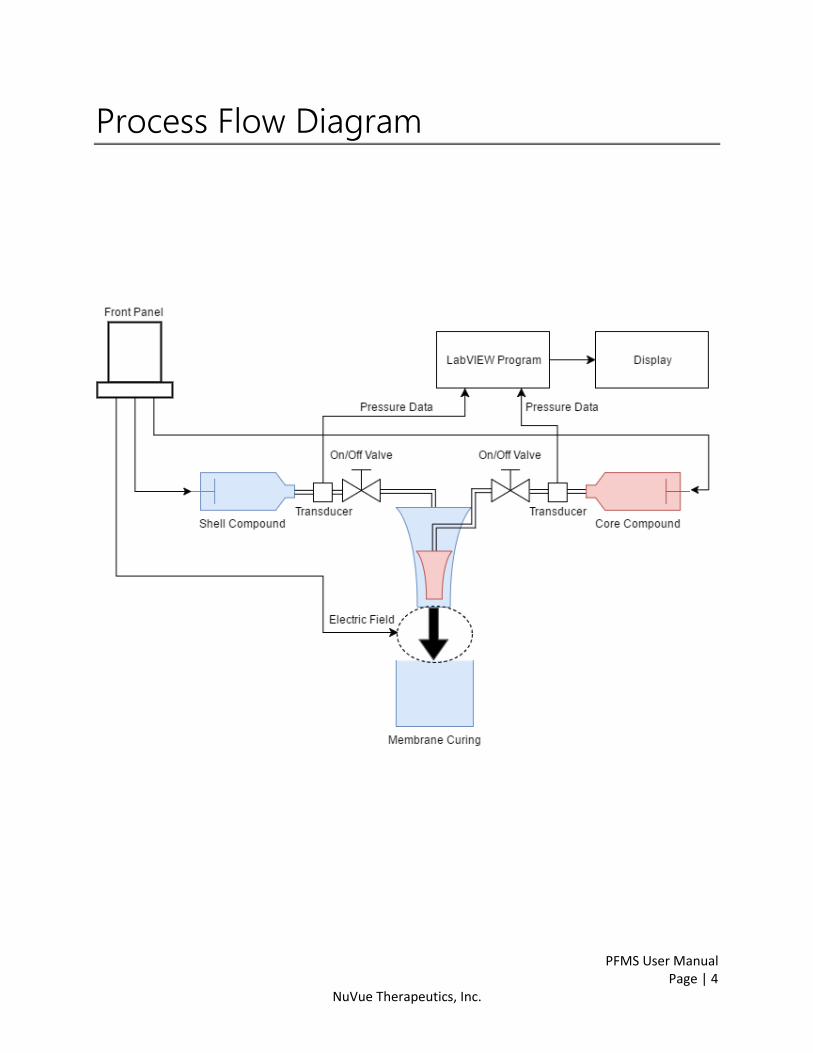
Mechanism For each batch of microcapsules, two syringe pumps are filled, one with the core compound and one
with the shell compound. The syringe pumps transport the fluids to a nested dual-nozzle system, with
the core compound in the inner nozzle and the shell compound in the outer nozzle.
A high-frequency pulse head causes uniform droplets to drop out of the inner nozzle and through the
outer nozzle, coating the core with the shell compound. An electrostatic field scatters the droplets as
they fall into a reservoir containing a third compound. This third compound reacts with the liquid shell
compound to form a solid membrane around the core compound, resulting in a microcapsule.
Software Function The PFMS Unit II is manually controlled by physical controls on the device’s front panel. These controls
regulate the piston speeds in the syringe pumps, the strength of the electrostatic field, and the pulse
head frequency and amplitude.
The LabVIEW program is used to monitor system data, including:
Rate at which the core and shell are formed
Pressures in the core and shell compound lines
Temperatures in the core and shell compound lines
Diameter of the core and shell
Magnitude of the electrostatic field
Frequency of the pulse head
PFMS User Manual
Page | 4 NuVue Therapeutics, Inc.
Process Flow Diagram

PFMS User Manual
Page | 5 NuVue Therapeutics, Inc.
Parts List
Part Number+A2:C35B45A2:B31A2:C37A2:C33A2:C34Description Notes
NVT2001-1 PFMS Chassis
NVT2002-1 PFMS Computer
NVT2003-1 Vibration Head Assembly EncapBioSystems IE-525 or equivalent
NVT2004-1 Two Syringe Pumps New Era NE-501
NVT2005-1 PFMS Top Cover
NVT3001-1 100um Shell Nozzle EncapBioSystems IE-5251-100 or equivalent
NVT3002-1 150um Shell Nozzle EncapBioSystems IE-5251-150 or equivalent
NVT3003-1 100um Core Nozzle EncapBioSystems IE-5253-100 or equivalent
NVT3004-1 150um Core Nozzle EncapBioSystems IE-5253-150 or equivalent
NVT3005-1 Stainless Steel Spatula
NVT3006-1 Stirrer Bar Magnet
NVT3007-1 200ml Glass Beaker
NVT3008-1 Liquid Inlet port EncapBioSystems IE-50R-116 or equivalent
NVT3009-1 Bead bypass assembly EncapBioSystems IE-50R-130 or equivalent
NVT3010-1 Membrane holder EncapBioSystems IE-50R-140 or equivalent
NVT3011-1 Thread to Hose Barb Adapter, 1/8" NPT(M) to 1/16" ID, PP, 25/Pk Cole-Parmer EW-06365-41 or equivalent
NVT4001-1 Pressure Transducer Module
NVT4002-1 High Voltage Cable
NVT4003-1 Ground Cable
NVT4004-1 Ground Probe
NVT4005-1 Electrical Stir Plate EncapBioSystems IE-50R-030 or equivalent
NVT4006-1 Generator (Frequency) PCB EncapBioSystems EMF100.82.11 or equivalent
NVT4007-1 Card Stroboscope PCB EncapBioSystems EMF100.82.12 or equivalent
NVT4008-1 Central Card, High Tension PCB EncapBioSystems EMF100.82.15-1 or equivalent
NVT4009-1 Electromagnetic Coil EncapBioSystems IE-50R-301 or equivalent
NVT4010-1 Bleed Valve Coral Non Iso. 12V, .032 orifice, SS with 1/8 NPT IQ Valve SS-930112-N8 or equivalent
NVT4011-1 Signal Amplifier, 4-20MA Control IQ Valve 20-090 or equivalent
NVT4012-1 PCO Control Board Measurement Computing USB-3104 or equivalent
NVT4015-1 Solid State Relay Omron G3A-225B-DC5-24 or equivalent
NVT4016-1 Power Supply Emerson NFS80-7606J or equivalent
NVT7001-1 Control Software Measurement Computing Dasylab or equivalent
NVT8001-1 1/16" ID Flex Silicone Tubing MasterFlex T-96410-14 or equivalent
NVT8002-1 50mL Conical Container Falcon 352098 or equivalent
NVT8003-1 15mL Conical Container Falcon 352099 or equivalent
NVT8004-1 Core Nozzle O-ring EncapBioSystems IE-5254 or equivalent
NVT8005-1 Shell Nozzle O-ring Fastenal #013 7/16"ID x 9/16"OD 0.063" Cross Section Nitrile Standard O-Ring or equivalent
NVT8006-1 Vibration Head O-ring Fastenal #016 5/8"ID x 3/4"OD 0.063" Cross Section Nitrile Standard O-Ring or equivalent
NVT8007-1 10ml Syringe B-D 14823 2A or equivalent
NVT8008-1 1/16" ID barbed tee fitting Cole-Parmer EW-30613-43 or equivalent
NVT8009-1 1/16" ID barbed male Luer fitting Cole-Parmer EW-45518-00 or equivalent
NVT8010-1 1/16" ID stainless barbed male Luer fitting Cole-Parmer EW-41507-26 or equivalent
NVT9001-1 NuVue PFMS User Manual
NVT9002-1 New Era NE-500/501 Syringe Pump Manual

PFMS User Manual
Page | 6 NuVue Therapeutics, Inc.
Hardware Setup Guide
Overview The procedures below are to be performed when installing and setting up the PFMS.
Hardware Installation
1. Connect PFMS chassis to 110VAC power source and toggle the latching power switch into the
ON position.
2. Connect PFMS laptop to 110VAC power source and push the power button above the
keyboard to turn on.
3. Connect PFMS laptop to PFMS chassis with water resistant USB cable.
Software Set-Up
1. Open the LabVIEW process monitoring program PFMS3.VI.
2. On the software interface, click PORT and select Port 1.
3. Click Connect to connect the PFMS device with the software.
The following tests should be performed after the PFMS has been transported, reinstalled after being
stored, or unused for an extended period of time.
Syringe Pump Operation Tests
1. Remove both syringes from syringe pumps if installed.
2. On each syringe pump, move plunger slide to the center.
3. Turn the syringe rate knob on PFMS front panel fully counter-clockwise.
4. Press the syringe pump “ON” button on PFMS front panel and verify syringe pump display is
illuminated.
5. Press and hold for 2 seconds the syringe pump “Turbo” button on PFMS front panel and verify
that both syringe pump plunger slides move forward.
6. Turn the syringe rate knob clockwise and verify syringe pump speed display increases and
pump slide moves forward. Return knob to fully counter-clockwise position when finished.
Vibration Head Operation Tests
1. Install vibration head assembly.
2. Install shell nozzle with o-ring.
3. Install transparent flexible tubing harness onto shell pump outlet, shell pressure sensor, and
shell nozzle valve inlet according to tubing diagram.
4. Place an empty collection beaker beneath the shell nozzle.
5. Fill the shell syringe with distilled water.
PFMS User Manual
Page | 7 NuVue Therapeutics, Inc.
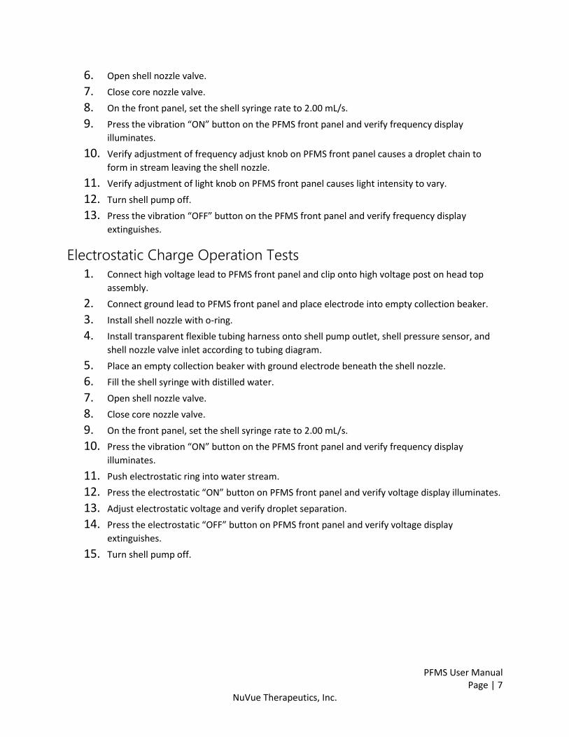
6. Open shell nozzle valve.
7. Close core nozzle valve.
8. On the front panel, set the shell syringe rate to 2.00 mL/s.
9. Press the vibration “ON” button on the PFMS front panel and verify frequency display
illuminates.
10. Verify adjustment of frequency adjust knob on PFMS front panel causes a droplet chain to
form in stream leaving the shell nozzle.
11. Verify adjustment of light knob on PFMS front panel causes light intensity to vary.
12. Turn shell pump off.
13. Press the vibration “OFF” button on the PFMS front panel and verify frequency display
extinguishes.
Electrostatic Charge Operation Tests
1. Connect high voltage lead to PFMS front panel and clip onto high voltage post on head top
assembly.
2. Connect ground lead to PFMS front panel and place electrode into empty collection beaker.
3. Install shell nozzle with o-ring.
4. Install transparent flexible tubing harness onto shell pump outlet, shell pressure sensor, and
shell nozzle valve inlet according to tubing diagram.
5. Place an empty collection beaker with ground electrode beneath the shell nozzle.
6. Fill the shell syringe with distilled water.
7. Open shell nozzle valve.
8. Close core nozzle valve.
9. On the front panel, set the shell syringe rate to 2.00 mL/s.
10. Press the vibration “ON” button on the PFMS front panel and verify frequency display
illuminates.
11. Push electrostatic ring into water stream.
12. Press the electrostatic “ON” button on PFMS front panel and verify voltage display illuminates.
13. Adjust electrostatic voltage and verify droplet separation.
14. Press the electrostatic “OFF” button on PFMS front panel and verify voltage display
extinguishes.
15. Turn shell pump off.
PFMS User Manual
Page | 8 NuVue Therapeutics, Inc.
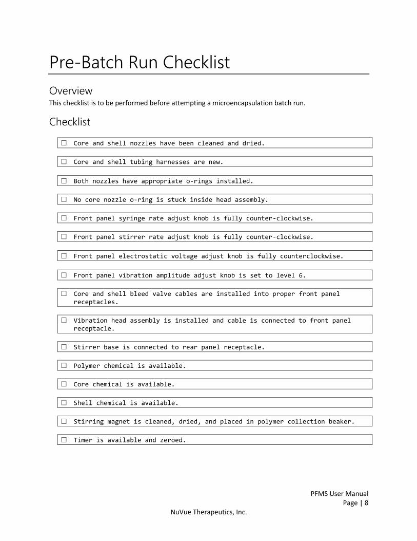
Pre-Batch Run Checklist
Overview This checklist is to be performed before attempting a microencapsulation batch run.
Checklist
□ Core and shell nozzles have been cleaned and dried.
□ Core and shell tubing harnesses are new.
□ Both nozzles have appropriate o-rings installed.
□ No core nozzle o-ring is stuck inside head assembly.
□ Front panel syringe rate adjust knob is fully counter-clockwise.
□ Front panel stirrer rate adjust knob is fully counter-clockwise.
□ Front panel electrostatic voltage adjust knob is fully counterclockwise.
□ Front panel vibration amplitude adjust knob is set to level 6.
□ Core and shell bleed valve cables are installed into proper front panel receptacles.
□ Vibration head assembly is installed and cable is connected to front panel receptacle.
□ Stirrer base is connected to rear panel receptacle.
□ Polymer chemical is available.
□ Core chemical is available.
□ Shell chemical is available.
□ Stirring magnet is cleaned, dried, and placed in polymer collection beaker.
□ Timer is available and zeroed.
PFMS User Manual
Page | 9 NuVue Therapeutics, Inc.
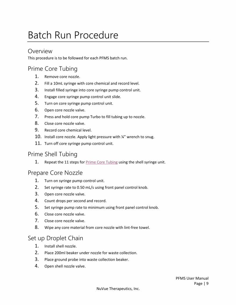
Batch Run Procedure
Overview This procedure is to be followed for each PFMS batch run.
Prime Core Tubing
1. Remove core nozzle.
2. Fill a 10mL syringe with core chemical and record level.
3. Install filled syringe into core syringe pump control unit.
4. Engage core syringe pump control unit slide.
5. Turn on core syringe pump control unit.
6. Open core nozzle valve.
7. Press and hold core pump Turbo to fill tubing up to nozzle.
8. Close core nozzle valve.
9. Record core chemical level.
10. Install core nozzle. Apply light pressure with ¼” wrench to snug.
11. Turn off core syringe pump control unit.
Prime Shell Tubing
1. Repeat the 11 steps for Prime Core Tubing using the shell syringe unit.
Prepare Core Nozzle
1. Turn on syringe pump control unit.
2. Set syringe rate to 0.50 mL/s using front panel control knob.
3. Open core nozzle valve.
4. Count drops per second and record.
5. Set syringe pump rate to minimum using front panel control knob.
6. Close core nozzle valve.
7. Close core nozzle valve.
8. Wipe any core material from core nozzle with lint-free towel.
Set up Droplet Chain
1. Install shell nozzle.
2. Place 200ml beaker under nozzle for waste collection.
3. Place ground probe into waste collection beaker.
4. Open shell nozzle valve.
PFMS User Manual
Page | 10 NuVue Therapeutics, Inc.
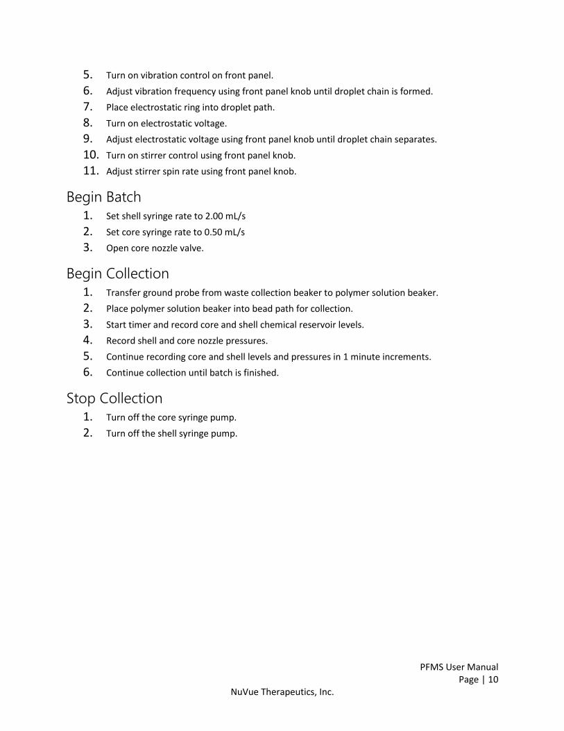
5. Turn on vibration control on front panel.
6. Adjust vibration frequency using front panel knob until droplet chain is formed.
7. Place electrostatic ring into droplet path.
8. Turn on electrostatic voltage.
9. Adjust electrostatic voltage using front panel knob until droplet chain separates.
10. Turn on stirrer control using front panel knob.
11. Adjust stirrer spin rate using front panel knob.
Begin Batch
1. Set shell syringe rate to 2.00 mL/s
2. Set core syringe rate to 0.50 mL/s
3. Open core nozzle valve.
Begin Collection
1. Transfer ground probe from waste collection beaker to polymer solution beaker.
2. Place polymer solution beaker into bead path for collection.
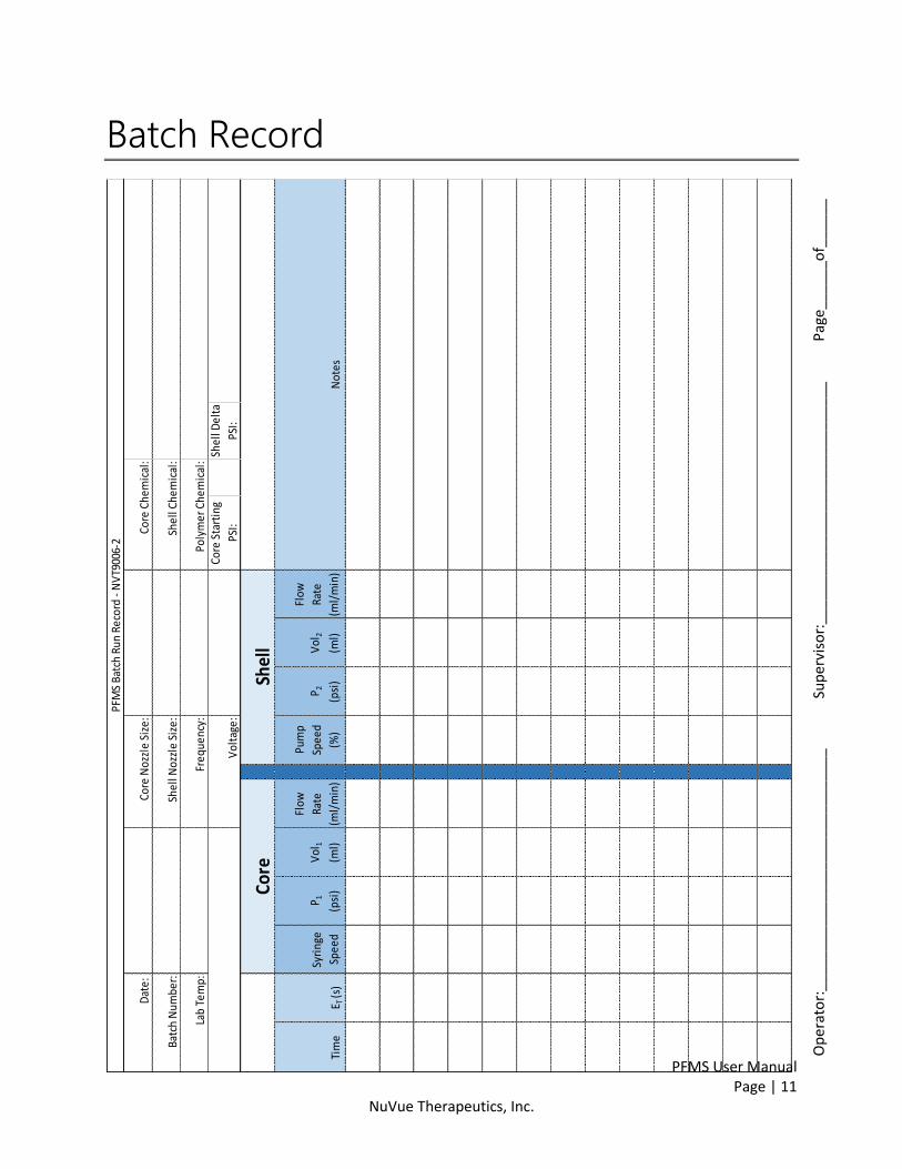
3. Start timer and record core and shell chemical reservoir levels.
4. Record shell and core nozzle pressures.
5. Continue recording core and shell levels and pressures in 1 minute increments.
6. Continue collection until batch is finished.
Stop Collection
1. Turn off the core syringe pump.
2. Turn off the shell syringe pump.
PFMS User Manual
Page | 11 NuVue Therapeutics, Inc.
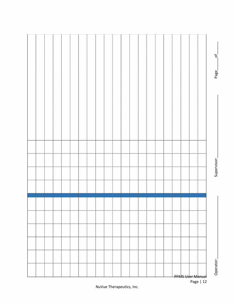
Batch Record
Tim
eE T
(s)
Syri
nge
Spee
d
P 1
(psi
)
Vol
1
(ml)
Flow
Rate
(ml/
min
)
Pum
p
Spee
d
(%)
P 2
(psi
)
Vol
2
(ml)
Flow
Rate
(ml/
min
)
Core
Shel
l
Core
Noz
zle
Size
:
Shel
l Noz
zle
Size
:
Freq
uenc
y:
Core
Che
mic
al:
Shel
l Che
mic
al:
Poly
mer
Che
mic
al:
PFM
S Ba
tch
Run
Reco
rd -
NV
T900
6-2
Core
Sta
rtin
g
PSI:
Shel
l Del
ta
PSI:
Not
es
Vol
tage
:
Dat
e:
Batc
h N
umbe
r:
Lab
Tem
p:
Op
erat
or:
___
____
___
___
___
____
___
___
___
_
Sup
ervi
sor:
___
___
___
___
___
____
___
___
___
__
Pag
e___
___o
f___
___
PFMS User Manual
Page | 12 NuVue Therapeutics, Inc.
Op
erat
or:
___
____
___
___
___
____
___
___
___
_
Sup
ervi
sor:
___
___
___
___
___
____
___
___
___
__
Pag
e___
___o
f___
___

PFMS User Manual
Page | 13 NuVue Therapeutics, Inc.
Shutdown and Cleanup Procedures
Overview The following procedures are to be performed after every microencapsulation batch run.
Reinitialize Settings
1. Set core syringe pump rate adjustment knob on PFMS front panel fully counter-clockwise.
2. Set shell syringe pump rate adjustment knob on PFMS front panel fully counter-clockwise.
3. Set stirrer speed adjustment knob on PFMS front panel to fully counter-clockwise.
4. Set electrostatic voltage adjustment knob on PFMS front panel to fully counter-clockwise.
Nozzle Removal and Cleaning
1. Close shell and core nozzle valves.
2. Remove shell and core nozzles.
3. Remove o-rings from nozzles and clean with water. Do not place o-rings in NaOH solution.
4. Flush nozzles with distilled water using Hydro Floss.
5. Place shell nozzle in 50mL plastic conical with 10mL of NaOH solution.
6. Place core nozzle in 15mL plastic conical with 3mL of NaOH solution.
7. Attach both nozzle conical on slow moving stirring table and allow NaOH solution to bathe
nozzles for at least 1 hour. Leave nozzles in NaOH solution until next use.
Remove Syringe Pumps
1. Disconnect tubing harness from core pressure sensor.
2. Pull back on core chemical syringe plunger to recover unused chemical from tubing harness.
3. Disconnect core chemical syringe from tubing harness.
4. Reinstall core tubing harness on to core pressure sensor.
5. Repeat steps 1-4 for the shell syringe pump.

PFMS User Manual
Page | 14 NuVue Therapeutics, Inc.
Tubing and Vibration Head Flush
1. Place an empty collection beaker under head assembly.
2. Fill 20mL syringe with distilled water.
3. Connect water-filled 20mL syringe to core tubing harness.
4. Open core nozzle valve.
5. Depress syringe plunger to stream water through the core tubing and head assembly.
6. Repeat steps 2-5 for the shell syringe pump.
7. Press the vibration control “ON” button on the PFMS front panel and verify display illuminates.
8. Adjust vibration frequency to 1000Hz using frequency adjust knob on PFMS front panel.
9. Set the shell pump rate to 2.00 mL/s.
10. Allow at least 40mL of water to pass through head assembly.
11. Turn off the shell syringe pump.
12. Close shell nozzle valve.
13. Press the vibration control “OFF” button on PFMS front panel and verify display extinguishes.
System Shutdown
1. Press Disconnect on the LabVIEW interface.
2. Toggle the locking power switch on the rear of the PFMS chassis to the OFF position.
3. Shutdown PFMS computer using the windows START menu.

PFMS User Manual
Page | 15 NuVue Therapeutics, Inc.
Service Procedures
Overview The following procedures should be used as necessary to maintain the PFMS system components.
Bleed Valve Service Procedures
Calibration of the IQ Coral Valve
1. Ensure that the system is powered on and the valve is properly attached to the OUTPUT+ and
OUTPUT- terminals of the signal amplifier.
2. Attach a digital multi-meter in parallel with the valve by attaching it to the OUTPUT+ and
OUTPUT- terminals of the signal amplifier.
3. Set both the IMIN and IMAX potentiometers to their minimum setting. This is done by
adjusting them counterclockwise 18 full turns.
4. Apply the minimum input command signal to the valve which is approximately 2.3 volts.
5. Slowly adjust the IMIN potentiometer clockwise until the voltage begins to increase linearly.
This is the minimum response point.
6. Adjust the IMAX potentiometer clockwise until the voltage reads approximately 12.5 volts.
This is the maximum response point.
7. Verify that a minimum voltage input to the signal amplifier results in a minimum valve
response.
8. Verify that a maximum voltage input to the signal amplifier results in a maximum valve
response. The calibration process is complete.
Bleed Valve Thorough Cleaning Procedure
1. Disconnect both of the valves from the signal amplifiers by removing the wires from the
OUTPUT+ and OUTPUT- terminals of the signal amplifiers.
2. Disconnect the inlet and outlet tubing to both the shell and core valves and remove the
assemblies from the system.
3. Using an open-ended wrench, remove the tubing adapters from the inlet and outlet ports of
both the shell and core valves.
4. Using a pair of retaining ring pliers, remove the small retaining ring at the top of each of the
valves.
5. Remove the cover plate and solenoid assembly from the pole piece of each valve body.
6. Unscrew the valve body and remove the top part of the valve body.
7. Using 70% isopropyl alcohol, clean the internal components of the valve.
8. Insert the valve bodies into an autoclave to sterilize the unit.
9. Ensure that the valve body is clean and dry.

PFMS User Manual
Page | 16 NuVue Therapeutics, Inc.
10. Reassemble the valve by reversing the steps of disassembly.
11. Re-install the valve into the system and complete the valve calibration procedure.
Pressure Transducer Replacement Procedure
1. Fully shutdown and power off PFMS system.
2. Remove pressure transducer module cable from PFMS chassis by twisting connector ring.
3. Remove old pressure transducer module by removing retaining screws from support posts.
4. Installed new pressure transducer module by inserting retaining screws through support posts
and into pressure transducer module casing.
5. Attach pressure transducer module cable to PFMS chassis.
PFMS User Manual
Page | 17 NuVue Therapeutics, Inc.
Appendix: Image Credits
Cover Background Image Stock image of a microscope. Digital image. Pixabay. N.p., 27 Feb. 2014. Web. 6 June 2016.
Process Flow Diagram James Lockwood. Diagram. Original content. 7 June 2016


![By: Faizan Alam Public Financial Management System(PFMS)Public Financial Management System(PFMS) Component Code: [Mandatory if the Transaction Code is ‘GP’] Component Code to be](https://static.documents.pub/doc/80x56/5f08391d7e708231d420f205/by-faizan-alam-public-financial-management-systempfms-public-financial-management.jpg)

