12

pg 1
pg 2
General Information.................................................................................................................3
Installation............................................................................................................................4~7
Wiring.................................................................................................................................8~10
Fine Tuning............................................................................................................................11
Pg.
Contents
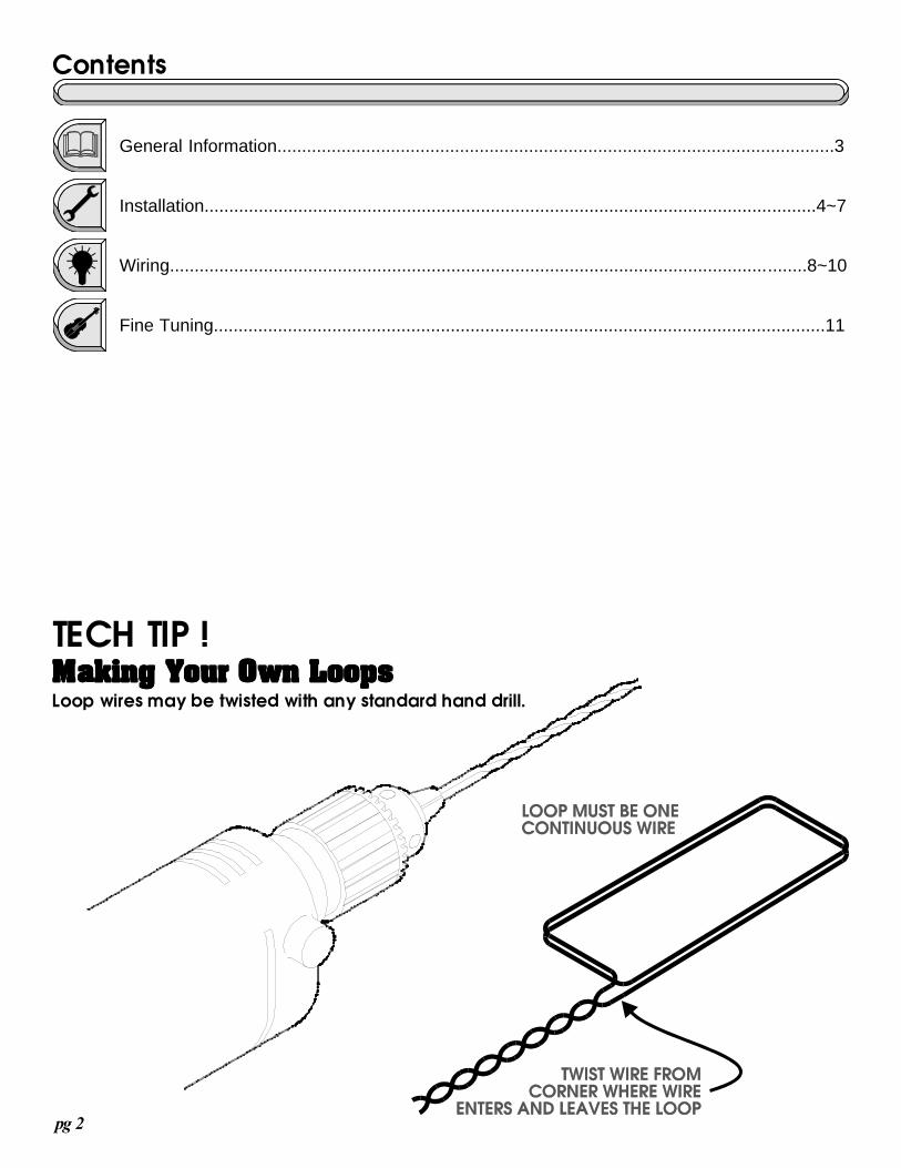
TECH TIP !Making Your Own LoopsMaking Your Own LoopsMaking Your Own LoopsMaking Your Own LoopsMaking Your Own LoopsLoop wires may be twisted with any standard hand drill.

pg 3
lllll OPEN AND SAFETY FUNCTIONSFor automatic gates, the terms open and safety have specific meaning when referring to the function of a gate
operator. The difference between these functions is determined by the gate operator and not by the loop detectors. What ismeant by an opening function is a function which will open and/or hold open an automatic gate. An opening function willopen an automatic gate in any position of the gate including the closed position, during the closing travel, or while the gateis stopped in mid travel. What is meant by a safety function is a function which will open and/or hold open an automaticgate while it is open or closing. A safety function will open an automatic gate in any position of the gate except the closedposition. This function is useful for gate operators that distinguish between the opening and closing directions of travelsuch as operators with auto close timers which will automatically close the gate after a number of seconds. A safetyfunction is important for peripherals such as safety loops which must be placed near the gate to hold it open if necessarybut cannot be used for unauthorized access through a closed entrance.
lllll EXIT AND SAFETY LOOPSExit and safety loops are equipment that connect to an automatic gate operator, commanding the operator to
perform either the open or the safety function. Open and safety loops normally consist of loops (coils of wire) which areplaced below the surface of the driveway and are connected to a loop detector which is placed close to or inside of the gateoperator.
lllll SHADOW LOOPSShadow loops add additional protection to swinging gates and can be used in addition to standard safety loops.
Loops are typically placed near but not in the path of the gate so that the metal gate will not effect the gates operation. Forswinging gates that are very long, the distance between safety loops may be too great to provide adequate protection tovehicles passing through. A shadow loop can be placed directly in the path of the gate and not effect operation.
lllll HOW DO LOOPS WORK?When a large metal object such as a car passes over the loops in the driveway, the loop detector which is con-
nected to the loops in the driveway senses the object and then gives a command to the gate operator. The operator willrespond to this command according to the function that the loop detector is connected to. Because the loop detector willsense only metal objects, a pedestrian will not be detected.
lllll WHAT ARE THE ADVANTAGES OF USING LOOPS?One of the greatest advantages to using loops is that they work with little or no effort. There is no need to get out of
a vehicle or even open a window. All that is required is simply driving across the loop. Another advantage of using loops isthat they must be triggered by a large metal object such as a vehicle which makes it difficult for anyone to use the loops forunauthorized access.
lllll WHAT ARE THE DISADVANTAGES OF USING LOOPS?One of the disadvantages of using loops in the case of safety loops is that they can detect only large metal objects
and thus do not detect a pedestrian. For automatic gate operators which have little or no internal safety features, it isrecommended that something in addition to safety loops be installed to protect pedestrians from possible injury.
lllll WHAT IS NEEDED TO INSTALL LOOPS?If an exit loop will be installed this requires a loop detector and an exit loop. The exit loop can be either a pre-
fabricated loop which can be installed before the driveway is paved or the loop can be cut and laid into an existing concreteor asphalt driveway. The exit loop can also be wired with two loops if needed (see wiring diagram page 7 for double loopopen input). If safety loops will be installed this requires a loop detector and a pair of safety loops that are installed on boththe inside and the outside of the gate. Safety loops can also be installed using only one loop on one side of the gate (seewiring diagram page 6 for single loop safety input). Because exit and safety loops perform two different functions, theyeach require their own loops and loop detectors. One loop detector cannot be used for both open and safety loops. If exitor safety loops will be cut into an existing concrete or asphalt driveway, a concrete cutting saw will be needed. These canbe rented at various equipment rental facilities. The blade on the saw must be 1/4 inch in width and capable of cutting atleast 2 inches in depth. The use of a shadow loop will also make an additional loop detector necessary.
General Informaton
pg 4
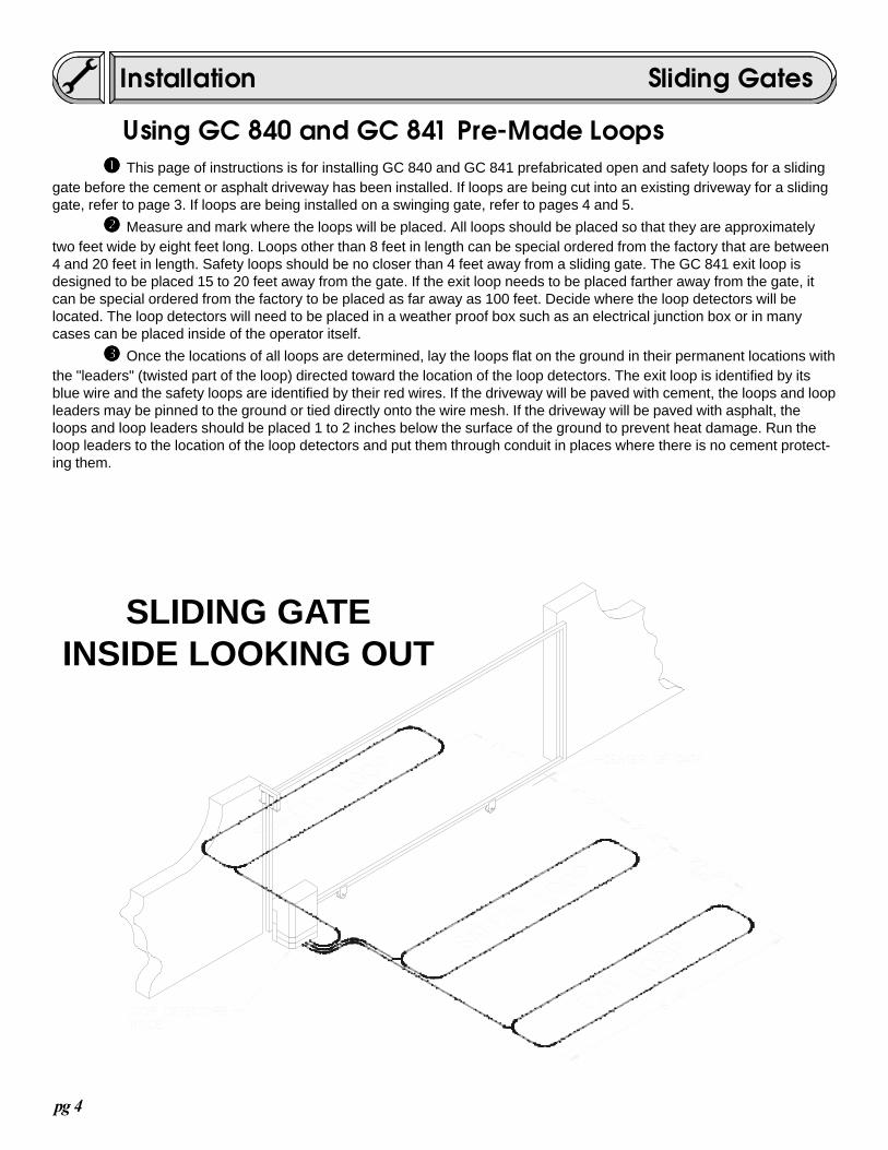
����� This page of instructions is for installing GC 840 and GC 841 prefabricated open and safety loops for a slidinggate before the cement or asphalt driveway has been installed. If loops are being cut into an existing driveway for a slidinggate, refer to page 3. If loops are being installed on a swinging gate, refer to pages 4 and 5.
����� Measure and mark where the loops will be placed. All loops should be placed so that they are approximatelytwo feet wide by eight feet long. Loops other than 8 feet in length can be special ordered from the factory that are between4 and 20 feet in length. Safety loops should be no closer than 4 feet away from a sliding gate. The GC 841 exit loop isdesigned to be placed 15 to 20 feet away from the gate. If the exit loop needs to be placed farther away from the gate, itcan be special ordered from the factory to be placed as far away as 100 feet. Decide where the loop detectors will belocated. The loop detectors will need to be placed in a weather proof box such as an electrical junction box or in manycases can be placed inside of the operator itself.
����� Once the locations of all loops are determined, lay the loops flat on the ground in their permanent locations withthe "leaders" (twisted part of the loop) directed toward the location of the loop detectors. The exit loop is identified by itsblue wire and the safety loops are identified by their red wires. If the driveway will be paved with cement, the loops and loopleaders may be pinned to the ground or tied directly onto the wire mesh. If the driveway will be paved with asphalt, theloops and loop leaders should be placed 1 to 2 inches below the surface of the ground to prevent heat damage. Run theloop leaders to the location of the loop detectors and put them through conduit in places where there is no cement protect-ing them.
Installation
SLIDING GATEINSIDE LOOKING OUT
Using GC 840 and GC 841 Pre-Made Loops
Sliding Gates
pg 5
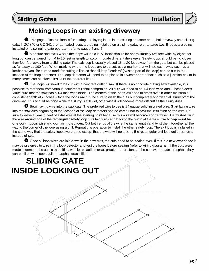
����� This page of instructions is for cutting and laying loops in an existing concrete or asphalt driveway on a slidinggate. If GC 840 or GC 841 pre-fabricated loops are being installed on a sliding gate, refer to page two. If loops are beinginstalled on a swinging gate operator, refer to pages 4 and 5.
����� Measure and mark where the loops will be cut. All loops should be approximately two feet wide by eight feetlong but can be varied from 4 to 20 feet in length to accommodate different driveways. Safety loops should be no closerthan four feet away from a sliding gate. The exit loop is usually placed 15 to 20 feet away from the gate but can be placedas far away as 100 feet. When marking where the loops are to be cut, use a marker that will not wash away such as alumber crayon. Be sure to mark for cutting a line so that all loop "leaders" (twisted part of the loop) can be run to thelocation of the loop detectors. The loop detectors will need to be placed in a weather proof box such as a junction box or inmany cases can be placed inside of the operator itself.
����� The loops will need to be cut with a concrete cutting saw. If there is no concrete cutting saw available, it ispossible to rent them from various equipment rental companies. All cuts will need to be 1/4 inch wide and 2 inches deep.Make sure that the saw has a 1/4 inch wide blade. The corners of the loops will need to cross over in order maintain aconsistent depth of 2 inches. Once the loops are cut, be sure to wash the cuts out completely and wash all slurry off of thedriveway. This should be done while the slurry is still wet, otherwise it will become more difficult as the slurry dries.
����� Begin laying wire into the saw cuts. The preferred wire to use is 14 gauge solid insulated wire. Start laying wireinto the saw cuts beginning at the location of the loop detectors and be careful not to scar the insulation on the wire. Besure to leave at least 3 feet of extra wire at the starting point because this wire will become shorter when it is twisted. Runthe wire around one of the rectangular safety loop cuts two turns and back to the origin of the wire. Each loop must beone continuous wire and contain no splices. Cut both ends of the wire the same length and twist them together all theway to the corner of the loop using a drill. Repeat this operation to install the other safety loop. The exit loop is installed inthe same way that the safety loops were done except that the wire will go around the rectangular exit loop cut three turnsinstead of two.
����� Once all loop wires are laid down in the saw cuts, the cuts need to be sealed over. If this is a new experience itmay be preferred to wire in the loop detector and test the loops before sealing (refer to wiring diagrams). If the cuts weremade in cement, the cuts can be filled with loop caulk, mortar, grout, or pour stone. If the cuts were made in asphalt, theycan be filled with loop caulk, or asphalt crack filler.
SLIDING GATEINSIDE LOOKING OUT
IntallationSliding Gates
Making Loops in an existing driveway
pg 6
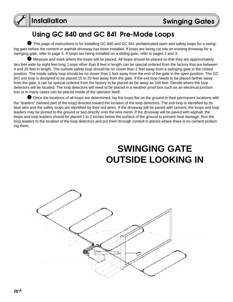
����� This page of instructions is for installing GC 840 and GC 841 prefabricated open and safety loops for a swing-ing gate before the cement or asphalt driveway has been installed. If loops are being cut into an existing driveway for aswinging gate, refer to page 5. If loops are being installed on a sliding gate, refer to pages 2 and 3.
����� Measure and mark where the loops will be placed. All loops should be placed so that they are approximatelytwo feet wide by eight feet long. Loops other than 8 feet in length can be special ordered from the factory that are between4 and 20 feet in length. The outside safety loop should be no closer than 2 feet away from a swinging gate in the closedposition. The inside safety loop should be no closer than 1 foot away from the end of the gate in the open position. The GC841 exit loop is designed to be placed 15 to 20 feet away from the gate. If the exit loop needs to be placed farther awayfrom the gate, it can be special ordered from the factory to be placed as far away as 100 feet. Decide where the loopdetectors will be located. The loop detectors will need to be placed in a weather proof box such as an electrical junctionbox or in many cases can be placed inside of the operator itself.
����� Once the locations of all loops are determined, lay the loops flat on the ground in their permanent locations withthe "leaders" (twisted part of the loop) directed toward the location of the loop detectors. The exit loop is identified by itsblue wire and the safety loops are identified by their red wires. If the driveway will be paved with cement, the loops and loopleaders may be pinned to the ground or tied directly onto the wire mesh. If the driveway will be paved with asphalt, theloops and loop leaders should be placed 1 to 2 inches below the surface of the ground to prevent heat damage. Run theloop leaders to the location of the loop detectors and put them through conduit in places where there is no cement protect-ing them.
SWINGING GATEOUTSIDE LOOKING IN
Installation
Using GC 840 and GC 841 Pre-Made Loops
Swinging Gates

pg 7
����� This page of instructions is for cutting and laying loops in an existing concrete or asphalt driveway for a swing-ing gate. If GC 840 or GC 841 pre-fabricated loops are being installed on a swinging gate, refer to page 4. If loops arebeing installed on a sliding gate operator, refer to pages 2 and 3.
����� Measure and mark where the loops will be cut. All loops should be approximately two feet wide by eight feetlong but can be varied between 4 and 20 feet in length to accommodate different driveways. The outside safety loop shouldbe 2 feet away from the gate in the closed position. The inside safety loop should be about 1 foot away from the end of thegate in the open position. The exit loop is normally placed 15 to 20 feet away from the gate but can be placed as far awayas 100 feet. When marking where the loops are to be cut, use a marker that will not wash away such as a lumber crayon.Be sure to mark for cutting a line so that all loop "leaders" (twisted part of the loop) can be run to the location of the loopdetectors. The loop detectors will need to be placed in a weather proof box such as an electrical junction box or in manycases it can be placed inside of the operator itself.
����� The loops will need to be cut with a concrete cutting saw. If there is no concrete cutting saw available, it ispossible to rent them from various equipment rental companies. All cuts will need to be 1/4 inch wide and 2 inches deep.Make sure that the saw has a 1/4 inch blade. The corners of the loops will need to cross over in order maintain a consis-tent depth of 2 inches. Once the loops are cut, be sure to wash the cuts out completely and wash all slurry off of thedriveway. This should be done while the slurry is still wet, otherwise it will become more difficult as the slurry dries.
����� Begin laying wire into the saw cuts. The preferred wire to use is 14 gauge solid insulated wire. Start laying wireinto the saw cuts beginning at the location of the loop detectors and be careful not to scar the insulation on the wire. Besure to leave at least 3 feet of extra wire at the starting point because this wire will become shorter when it is twisted. Runthe wire around one of the rectangular safety loop cuts two turns and back to the origin of the wire. Each loop must beone continuous wire and contain no splices. Cut both ends of the wire the same length and twist them together all theway to the corner of the loop using a drill. Repeat this operation to install the other safety loop. The exit loop is installed inthe same way that the safety loops were done except that the wire will go around the rectangular exit loop cut three turnsinstead of two.
����� Once all loop wires are laid down in the saw cuts, the cuts need to be sealed over. If this is a new experience itmay be preferred to wire in the loop detector and test the loops before sealing (refer to wiring diagrams). If the cuts weremade in cement, the cuts can be filled with loop caulk, mortar, grout, or pour stone. If the cuts were made in asphalt, theycan be filled with loop caulk, or asphalt crack filler.
SWINGING GATEOUTSIDE LOOKING IN
Intallation
Making Loops in an existing driveway
Swinging Gates
pg 8
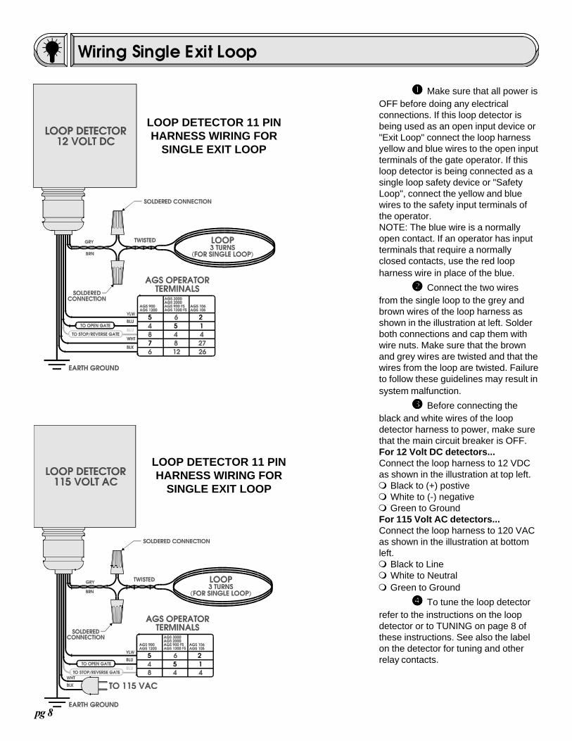
����� Make sure that all power isOFF before doing any electricalconnections. If this loop detector isbeing used as an open input device or"Exit Loop" connect the loop harnessyellow and blue wires to the open inputterminals of the gate operator. If thisloop detector is being connected as asingle loop safety device or "SafetyLoop", connect the yellow and bluewires to the safety input terminals ofthe operator.NOTE: The blue wire is a normallyopen contact. If an operator has inputterminals that require a normallyclosed contacts, use the red loopharness wire in place of the blue.
����� Connect the two wiresfrom the single loop to the grey andbrown wires of the loop harness asshown in the illustration at left. Solderboth connections and cap them withwire nuts. Make sure that the brownand grey wires are twisted and that thewires from the loop are twisted. Failureto follow these guidelines may result insystem malfunction.
����� Before connecting theblack and white wires of the loopdetector harness to power, make surethat the main circuit breaker is OFF.For 12 Volt DC detectors...Connect the loop harness to 12 VDCas shown in the illustration at top left.m Black to (+) postivem White to (-) negativem Green to GroundFor 115 Volt AC detectors...Connect the loop harness to 120 VACas shown in the illustration at bottomleft.m Black to Linem White to Neutralm Green to Ground
����� To tune the loop detectorrefer to the instructions on the loopdetector or to TUNING on page 8 ofthese instructions. See also the labelon the detector for tuning and otherrelay contacts.
LOOP DETECTOR 11 PINHARNESS WIRING FOR
SINGLE EXIT LOOP
Wiring Single Exit Loop
LOOP DETECTOR 11 PINHARNESS WIRING FOR
SINGLE EXIT LOOP
pg 9
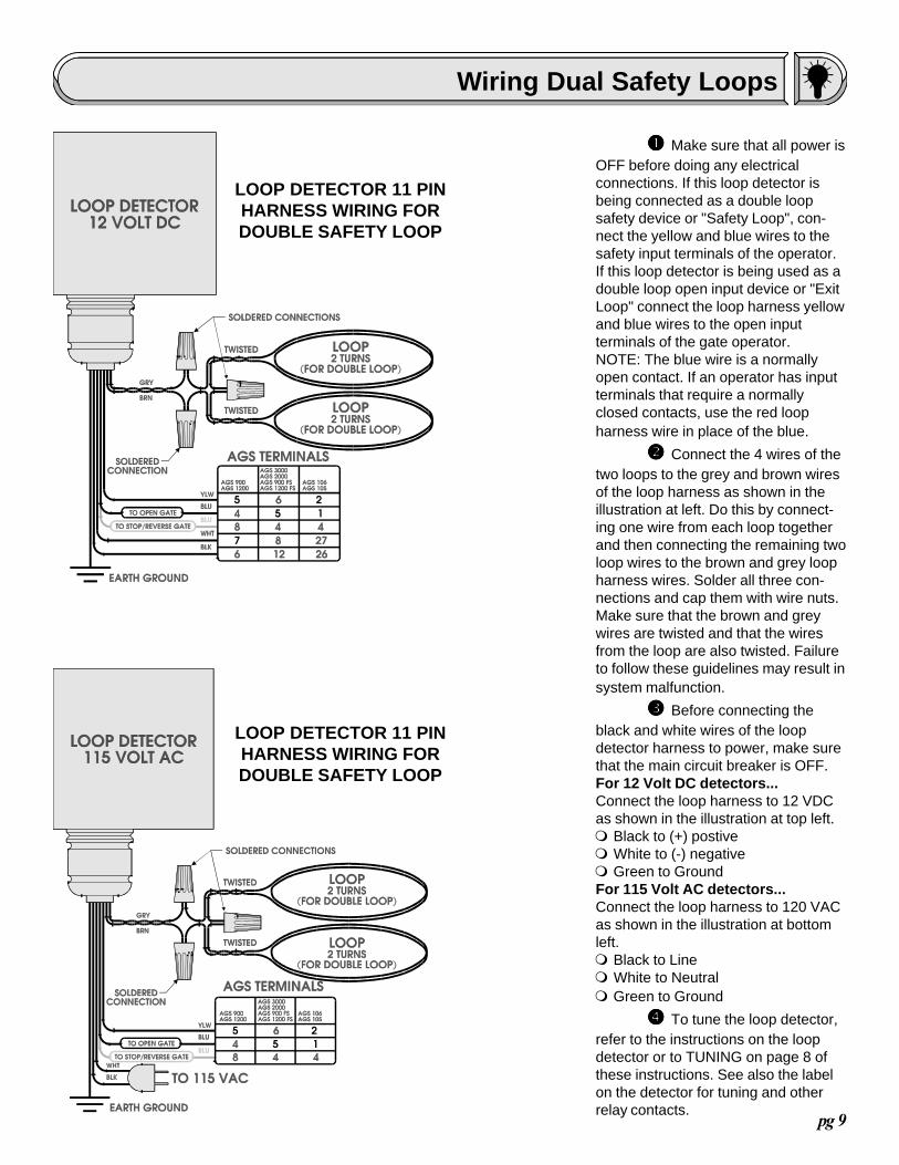
����� Make sure that all power isOFF before doing any electricalconnections. If this loop detector isbeing connected as a double loopsafety device or "Safety Loop", con-nect the yellow and blue wires to thesafety input terminals of the operator.If this loop detector is being used as adouble loop open input device or "ExitLoop" connect the loop harness yellowand blue wires to the open inputterminals of the gate operator.NOTE: The blue wire is a normallyopen contact. If an operator has inputterminals that require a normallyclosed contacts, use the red loopharness wire in place of the blue.
����� Connect the 4 wires of thetwo loops to the grey and brown wiresof the loop harness as shown in theillustration at left. Do this by connect-ing one wire from each loop togetherand then connecting the remaining twoloop wires to the brown and grey loopharness wires. Solder all three con-nections and cap them with wire nuts.Make sure that the brown and greywires are twisted and that the wiresfrom the loop are also twisted. Failureto follow these guidelines may result insystem malfunction.
����� Before connecting theblack and white wires of the loopdetector harness to power, make surethat the main circuit breaker is OFF.For 12 Volt DC detectors...Connect the loop harness to 12 VDCas shown in the illustration at top left.m Black to (+) postivem White to (-) negativem Green to GroundFor 115 Volt AC detectors...Connect the loop harness to 120 VACas shown in the illustration at bottomleft.m Black to Linem White to Neutralm Green to Ground
����� To tune the loop detector,refer to the instructions on the loopdetector or to TUNING on page 8 ofthese instructions. See also the labelon the detector for tuning and otherrelay contacts.
Wiring Dual Safety Loops
LOOP DETECTOR 11 PINHARNESS WIRING FORDOUBLE SAFETY LOOP
LOOP DETECTOR 11 PINHARNESS WIRING FORDOUBLE SAFETY LOOP
pg 10
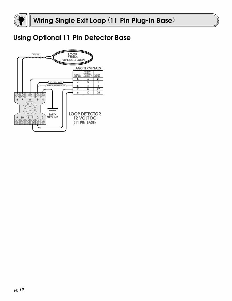
Wiring Single Exit Loop (11 Pin Plug-In Base)
Using Optional 11 Pin Detector Base

pg 11
625X1) Set the frequency (FREQ). If there is only one detector being used, the frequency can be set to any one of the threesettings "H" high, "M" medium or "L" low. If more than one detector is being used, set each detector different from the next.Examples:a) single detector: Set frequency switch to "H"b) two detectors: Set the switch on one detector to "H" and the other to "L"c) three detectors: Set one detector freq to "H", another to "M" and the last one to "L"2) Set the Sensitivity: This determines how large or how small the metal object must be in order for the detector to sense it.The possible settings are "H" high, "M" medium, "L" low. The "H" setting will typically detect smaller objects and highervehicles. The "L" setting typically requires larger and closer objects. Set this switch so that the detector will detect a vehicleof representative size and height and so that the metal gate will not effect the detector. If more sensitivity is required, setswitch one on the back of the detector to ON. This will double the sensitivity.3) Set the Logic: This will determine what the detector does when it is activated by a car.a) Pulse on entry: (Switch 3 OFF and Switch 2 OFF) This setting will make the detector activate for one second as soon asthe vehicle approaches the loop.b) Pulse on exit: (Switch 3 ON and Switch 2 OFF) This setting will make the loop detector activate for one second as soonas the vehicle has passed beyond the loop.c) Presence: (Switch 3 OFF and Switch 2 ON) This setting will make the loop detector activate continuously as long as thevehicle remains on the loop. (This is the most common setting)4) Initiate the Detector: After all the switches have been set, initialize the detector by pressing and holding the reset buttonfor more that 3 seconds.
525AX1) Set the frequency. If there is only one detector being used, the frequency can be set to any one of the four settings high,medium-high, medium-low, or low. If more than one detector is being used, set each detector different from the next.Examples:a) single detector: Set frequency switches to F0 and F0b) two detectors: Set the switches on one detector to F0 and F0, set the other detector to F1 and F0c) three detectors: Set one detector freq to F0 and F0, another to F1 and F0, and the last one to F0 and F22) Set the Sensitivity: This determines how large or how small the metal object must be in order for the detector to sense it.The possible settings range from high to low to off and are controlled by switches 1, 2 and 3. The normal settings areswitch 1 to 0, switch 2 to 2, and switch 3 to 4. For other settings, see the description label located on the loop detector.3) Set the Logic: This will determine what the detector does when it is activated by a car.a) Pulse on entry: (Set pulse switch to EN) This setting will make the detector activate for one second as soon as thevehicle approaches the loop.b) Pulse on exit: (Set pulse switch to LV) This setting will make the loop detector activate for one second as soon as thevehicle has passed beyond the loop.c) Presence: (Set PRES switch to HI) This setting will make the loop detector activate continuously as long as the vehicleremains on the loop. (This is the most common setting)4) Initiate the Detector: After all the switches have been set, initialize the detector by pressing and holding the reset buttonfor more that 3 seconds.
LD20001) Set the frequency (FREQ). If there is only one detector being used, the frequency can be set to any one of the threesettings "H" high, "M" medium or "L" low. If more than one detector is being used, set each detector different from the next.Examples:a) single detector: Set frequency switch to "H"b) two detectors: Set the switch on one detector to "H" and the other to "L"c) three detectors: Set one detector freq to "H", another to "M" and the last one to "L"2) Initiate the Detector: After all the switches have been set, initialize the detector by pressing and holding the reset buttonfor more that 3 seconds.3) If sensitivity needs to be changed, there are switches located inside the detector for sensitivity and Fail Safe/Securemodes of operation. See instructions provided with the detector.
Fine Tuning

pg 12Revision: 10/19/99


