Instruction No. / Número de instrucción PG_207_SW_54VZ#01 Page / Página 1 / 9 Instruction No. / Número de instrucción: PG_207_SW_54VZ#01 Revision number / Número de revisión: 1 Revision date / Fecha de revisión 25-09-08 Vehicleclass / Clasificación del vehículo: M1 Carbrand/ Marca del coche: Peugeot Type/ Tipo : 207 Body type / Tipo de carrocería: SW Year of construction / Año de construcción: 2007 Tank situation / Tipo de depósito: Torodial / Toroidal Gros volume / Contenido bruto: 54 L European Approval/ Aprobación europea: E1 # 115R – 0000xx Powered by: Vogels Autogas Ekkersrijt 3016 5692 CA Son Nederland Telephone: +31 (0)499 - 473229 Fax: +31 (0)499 - 460762 E-mail : [email protected]Online : www.vogelsautogas.nl Green Power Systems Distributor de Equipos VOGELS AUTOGAS por España C/ Pere Geronès, 2-8 Santa Cristina d'Aro Girona 17246 Catalunya, España Tel: +34 (0)972 835014 E-mail : [email protected]Online : www.vogelsautogas.es
Transcript
Instruction No. / Número de instrucción PG_207_SW_54VZ#01 Page / Página 1 / 9
Instruction No. / Número de instrucción: PG_207_SW_54VZ#01 Revision number / Número de revisión: 1 Revision date / Fecha de revisión 25-09-08 Vehicleclass / Clasificación del vehículo: M1 Carbrand/ Marca del coche: Peugeot Type/ Tipo : 207 Body type / Tipo de carrocería: SW Year of construction / Año de construcción: 2007 � Tank situation / Tipo de depósito: Torodial / Toroidal Gros volume / Contenido bruto: 54 L European Approval/ Aprobación europea: E1 # 115R – 0000xx
Powered by:
Vogels Autogas Ekkersrijt 3016 5692 CA Son Nederland Telephone: +31 (0)499 - 473229 Fax: +31 (0)499 - 460762 E-mail : [email protected] Online : www.vogelsautogas.nl
Green Power Systems Distributor de Equipos VOGELS AUTOGAS por España C/ Pere Geronès, 2-8 Santa Cristina d'Aro Girona 17246 Catalunya, España Tel: +34 (0)972 835014 E-mail : [email protected] Online : www.vogelsautogas.es
Instruction No. / Número de instrucción PG_207_SW_54VZ#01 Page / Página 2 / 9
General instructions / Instrucciones generales: English : • Disconnect the battery before installation. It might be that radio codes, automatic door lock systems and/or alarm devices don’t work properly after installation and have to be reinitiated try to prevent this by connecting a special power supply. • The installation has to be done according R115 and R67 regulations and possible national regulations of specific countries. • For general technical information you have to use the Manual de Componentes e Instalación. • Use the original car’s workshop manual for dismantling and assembling of original car parts • All mentioned directions are based on the drivers position, behind the steering wheel • All mentioned dimensions and wire colours should be checked on the vehicle before holes are drilled and wires are cut or connected. • All electrical connections should be made with appropriate materials and should be covered against shortcut. • Cylinder 1 is always the cylinder next to the distribution • Always use an anti-corrosion coating where necessary to prevent for rust. • Avoid any water entering the interior of the vehicle by the wiring loom. All arising slits have to be sealed with sealing silicon • These fitting instructions only contain specific information about this type of vehicle. For further information always refer to the technical users manual When these fitting instructions are not (properly) followed, it can lead to an improper functioning of the LPG installation or even to dangerous situations. All consequences of this matter are on the installers responsibility. Despite of all our efforts regarding these instructions, Vogels GLP can not be held responsible for any error, mistake or non-completeness that might be entered in these manuals. Published by Vogels GLP Español: • Desconecte la batería al empezar la instalación del sistema GLP. Note: puede ocurrir que los ajustes de un radio se borren, que el sistema de cierre automático de las portezuelas se active y que la alarma suene. Se lo puede prevenir con un equipo especial apto para mantener la tensión a bordo. • Para todas las informaciones generales técnicas sobre el kit, se utiliza el Manual de Componentes e Instalación • El equipo GLP debe ser instalado conforme a las directivas R115 y R67 así como los requisitos y prescripciones adicionales del país correspondiente. • Utilice el manual de taller (el original del coche) para el (des)montaje de las partes originales. • Todas las direcciones mencionadas en este manual se basan en la posición del conductor, es decir detrás el volante. • Las medidas y los colores del cableado siempre deben ser controlados, en relación con diferencias entre coches y posibles alteraciones . • Las Conexiones eléctricas deben ser hechas con los materiales apropiados, preferiblemente soldados, y deben ser protegidas contra un cortocircuito y corrosión. • El cilindro 1 (o A), como está descrito en esta ficha, se encuentra al lado de la distribución del motor. • Siempre debe utilizar una capa anti-corrosión donde se la necesita como protección contra la herrumbre. • Ponga el cableado en tal posición que no puede entrar agua en el interior del vehículo. Prevenga molestias por el ruido o escape de agua del compartimento del motor al interior del vehículo. • Para otras instrucciones y la definición del sistema referimos al manual general del sistema. Si las instrucciones descritas en esta ficha no se cumplen o se cumplen incorrectamente, puede causar un sistema de gas que no funcione y/o una situación peligrosa. El instalador es responsable de las consecuencias. A pesar de haber puesto mucho esmero en la composición de esta edición, no se puede hacer responsable a Vogels GLP de cualquier error, equivocación o deficiencia que pudieran proceder de esta edición. Editado por Vogels GLP
Instruction No. / Número de instrucción PG_207_SW_54VZ#01 Page / Página 3 / 9
Overview of Homologation numbers / Panorama de números de homologación: Component / Componente R67 Tank / Depósito E20 67R-010618 Filler hose / Tubería de llenado E4 67R-010074 Filler / Dispositivo de llenado E8 67R-011329 1. Preparations / Preparaciones Fig. 1a Fig. 1b
Fig. 1c Fig. 1d
Instruction No. / Número de instrucción PG_207_SW_54VZ#01 Page / Página 4 / 9
Fig. 1e
Fig. 1f Fig. 1g
Remarks / Observaciones : All interior lining, rear bumper and rear exterior as well as interior panels that could be damaged or dirtied during the installation of the rear kit, should be removed before installation works begin. It can also be necessary to disassemble these parts in order to create more space. El contrachoques y los paneles exteriores e interiores siempre tienen que estar protegidos contra daños causados por el montaje del depósito. Además puede ser necesario quitar el tapizado del maletero para crear espacio y prevenir daños y contaminación.
Instruction No. / Número de instrucción PG_207_SW_54VZ#01 Page / Página 5 / 9
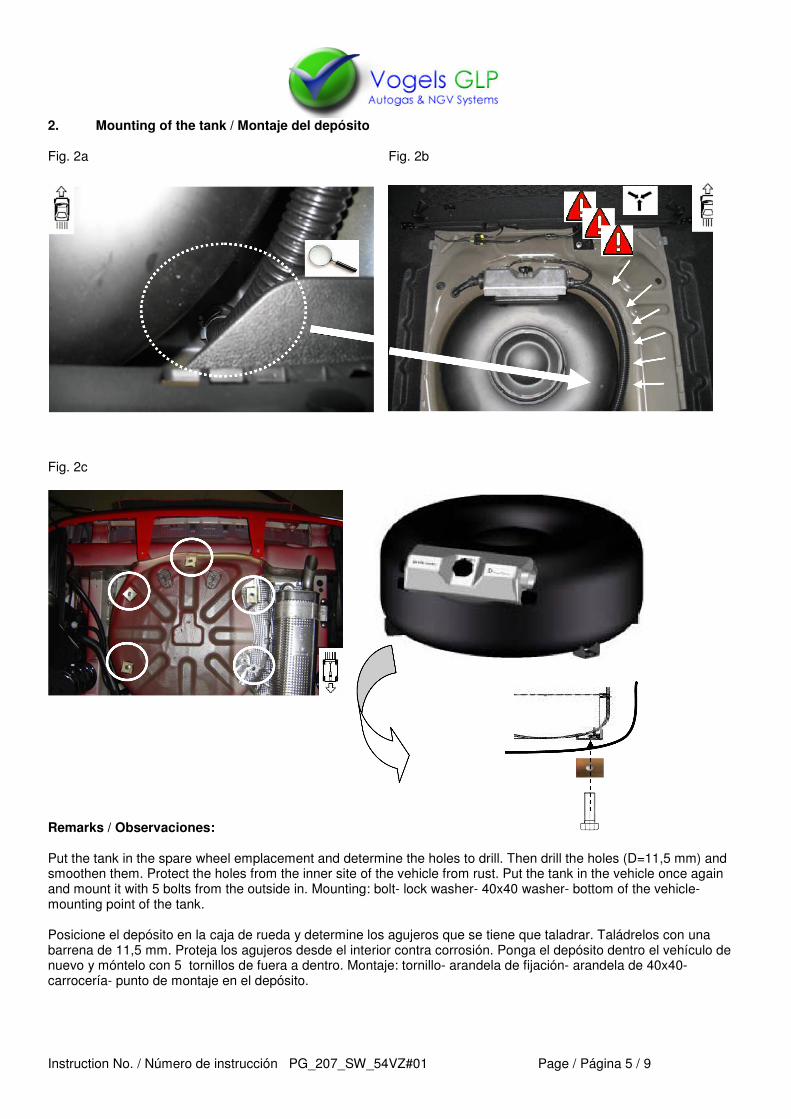
2. Mounting of the tank / Montaje del depósito Fig. 2a Fig. 2b
Fig. 2c
Remarks / Observaciones: Put the tank in the spare wheel emplacement and determine the holes to drill. Then drill the holes (D=11,5 mm) and smoothen them. Protect the holes from the inner site of the vehicle from rust. Put the tank in the vehicle once again and mount it with 5 bolts from the outside in. Mounting: bolt- lock washer- 40x40 washer- bottom of the vehicle-mounting point of the tank. Posicione el depósito en la caja de rueda y determine los agujeros que se tiene que taladrar. Taládrelos con una barrena de 11,5 mm. Proteja los agujeros desde el interior contra corrosión. Ponga el depósito dentro el vehículo de nuevo y móntelo con 5 tornillos de fuera a dentro. Montaje: tornillo- arandela de fijación- arandela de 40x40-carrocería- punto de montaje en el depósito.
Instruction No. / Número de instrucción PG_207_SW_54VZ#01 Page / Página 6 / 9
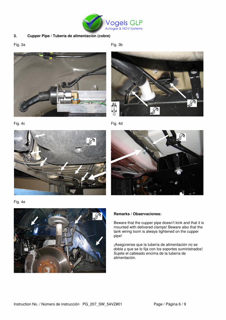
Remarks / Observaciones: Beware that the cupper pipe doesn’t kink and that it is mounted with delivered clamps! Beware also that the tank wiring loom is always tightened on the cupper pipe! ¡Asegúrense que la tubería de alimentación no se dobla y que se lo fija con los soportes suministrados! Sujete el cableado encima de la tubería de alimentación.
Instruction No. / Número de instrucción PG_207_SW_54VZ#01 Page / Página 7 / 9
4. Filler/ dispositivo de llenado Fig. 4a Fig. 4b
Fig. 4c2 Fig. 4d2
Fig. 4e2 Fig. 4f2
Instruction No. / Número de instrucción PG_207_SW_54VZ#01 Page / Página 8 / 9
5. Electrical connections / Conexiones eléctricas Connect the wiring loom to the tank’s coil and level indicator, using the electrical scheme below. Conecte el cableado del sensor del depósito y de la válvula del depósito según el esquema eléctrico debajo de este texto.
Rd Red / Rojo Wh White / Blanco Wh/Bk White-Black / Blanco-Negro Bk Black / Negro Bl Blue / Azul Gr Green / Verde Use provided heatshrink to assure a good insulation of the solder connections. Beware that the heatshrinks are well shrunk around the solder connection. Utilice los aisladores térmicos suministrados para soldar las conexiones eléctricas al depósito. Asegúrense que los aisladores térmicos se han encogido bien alrededor de la conexión con el cableado. Finishing / Terminación Treat all metal parts of placed components, mentioned in these instructions, with an anti-corrosion coating. Mount the special spare wheel cover and put the tyre reparation kit in the hand glove department. Protégense todas las partes metálicas de los componentes instalados, mencionados en estas instrucciones, con un anticorrosivo. Póngase la cobertura a la rueda de recambio y meta el kit de reparación de ruedas que se ha suministrado en la guantera. Informe el cliente.
Instruction No. / Número de instrucción PG_207_SW_54VZ#01 Page / Página 9 / 9
Used Symbols / Símbolos utilizados Front view Vista frontal Rear view Vista trasera Bottom view Vista de fondo Top view Vista de arriba Part to be removed Parte para remover Cut Cortar Assemble part Ensamblar parte Disassemble part Desmontar parte Moving parts Partes en movimiento
Thread hole Abertura de la rosca Thread end Fin de la rosca Bolt Tornillo Nut Tuerca Drill Taladro Tap Espita Provided Clamp Soporte suministrado Original Clamp Soporte original Attention Atención