PLEASE READ This manual is provided as a free service by Projector.com. We are in no way responsible for the contents of the manual. We do not guarantee its accuracy and we do not make any claim of copyright. The copyright remains the property of their respective owners. ABOUT PROJECTOR.COM Projector.com (http://www.projector.com ) is your review and buying guide resource for DLP and LCD video projectors. Visit the site to read the latest projector news and reviews, read and comment on projector specifications, download user manuals and much more.
Transcript
PLEASE READ This manual is provided as a free service by Projector.com. We are in no way responsible for the contents of the manual. We do not guarantee its accuracy and we do not make any claim of copyright. The copyright remains the property of their respective owners. ABOUT PROJECTOR.COM Projector.com (http://www.projector.com) is your review and buying guide resource for DLP and LCD video projectors. Visit the site to read the latest projector news and reviews, read and comment on projector specifications, download user manuals and much more.
This equipment complies with the requirements of Directives 89/336/EEC and 73/23/EEC as amended by 93/68/EEC.
Dieses Gerät entspricht den Anforderungen der EG-Richtlinien 89/336/EWG und 73/23/EWG mit Änderung 93/68/EWG.
Ce matériel répond aux exigences contenues dans les directives 89/336/CEE et 73/23/CEE modifiées par ladirective 93/68/CEE.
Dit apparaat voldoet aan de eisen van de richtlijnen 89/336/EEG en 73/23/EEG, gewijzigd door 93/68/EEG.
Dette udstyr overholder kravene i direktiv nr. 89/336/EEC og 73/23/EEC med tillæg nr. 93/68/EEC.
Quest’ apparecchio è conforme ai requisiti delle direttive 89/336/EEC e 73/23/EEC, come emendata dalladirettiva 93/68/EEC.
Η εγκατάσταση αυτή ανταπκρίνεται στις απαιτήσεις των δηγιών της Ευρωπαϊκής Ενωσης 89/336/ΕΚ και 73/23/ΕΚ, #πως ι καννισµί αυτί συµπληρώθηκαν απ# την δηγία 93/68/ΕΚ.
Este equipamento obedece às exigências das directivas 89/336/CEE e 73/23/CEE, na sua versão corrigidapela directiva 93/68/CEE.
Este aparato satisface las exigencias de las Directivas 89/336/CEE y 73/23/CEE, modificadas por medio de la93/68/CEE.
Denna utrustning uppfyller kraven enligt riktlinjerna 89/336/EEC och 73/23/EEC så som kompletteras av 93/68/EEC.
Dette produktet oppfyller betingelsene i direktivene 89/336/EEC og 73/23/EEC i endringen 93/68/EEC.
Tämä laite täyttää direktiivien 89/336/EEC ja 73/23/EEC vaatimukset, joita on muutettu direktiivillä 93/68/EEC.
IMPORTANTFor your assistance in reporting the loss or theft of yourProjector, please record the Serial Number located onthe bottom of the projector and retain this information.Before recycling the packaging, please be sure thatyou have checked the contents of the carton thoroughlyagainst the list of “Supplied accessories” on page 20.
Model No.: PG-M25X
Serial No.:
GyroRemoteThis equipment complies with the requirements of Directive 1999/5/EC.
GyroRemote-FernbedienungDieses Gerät entspricht den Anforderungen der EU-Richtlinie 1999/5/EG.
GyroRemoteCet appareil est conforme aux exigences de la directive 1999/5/CE.
GyroRemoteDit apparaat voldoet aan de eisen van de richtlijn 1999/5/EG.
GyroFjernbetjeningDette udstyr overholder kravene i direktiv 1999/5/EF.
GyroRemoteQuest’ apparecchio è conforme ai requisiti delle direttiva 1999/5/CE.
GyroRemotoEste equipamento obedece às exigências da directiva 1999/5/CE.
GyroRemoteEste aparato satisface las exigencias de las Directiva 1999/5/CE.
GyrofjärrkontrollDenna utrustning uppfyller kraven enligt direktiv 1999/5/EC.
GyroRemoteDette produktet oppfyller kravene i direktiv 1999/5/EC.
Gyro-kauko-ohjainTämä laite täyttää direktiivin 1999/5/EY vaatimukset.
PG-M25X#E#Hyo2.p65 02.4.29, 3:03 PM1
Downlo
aded
from
Pro
jecto
r.com
PG-M25X#Ep00.p65 02.4.29, 3:05 PM2
Downlo
aded
from
Pro
jecto
r.com
The supplied CD-ROM contains operation instructions in English, German, French, Swedish, Spanish, Italian,Dutch, Portuguese, Chinese and Korean. Carefully read through the operation instructions before operating theprojector.
Die mitgelieferte CD-ROM enthält Bedienungsanleitungen in Englisch, Deutsch, Französisch, Schwedisch, Spanisch,Italienisch, Niederländisch, Portugiesisch, Chinese, und Koreanisch. Bitte lesen Sie die Bedienungsanleitung vor derVerwendung des Projektors sorgfältig durch.
Le CD-ROM fourni contient les instructions de fonctionnement en anglais, allemand, français, suédois,espagnol, italien, néerlandais, portugais, chinois et coréen. Veuillez lire attentivement ces instructions avant defaire fonctionner le projecteur.
Den medföljande CD-ROM-skivan innehåller bruksanvisningar på engelska, tyska, franska, svenska, spanska,italienska, holländska, portugisiska, kinesiska och koreanska. Läs noga igenom bruksanvisningen innanprojektorn tas i bruk.
El CD-ROM suministrado contiene instrucciones de operación en inglés, alemán, francés, sueco, español,italiano, holandés, portugués, chino y coreano. Lea cuidadosamente las instrucciones de operación antes deutilizar el proyector.
Il CD-ROM in dotazione contiene istruzioni per l’uso in inglese, tedesco, francese, svedese, spagnolo, italiano,olandese, portoghese, cinese e coreano. Leggere attentamente le istruzioni per l’uso prima di usare ilproiettore.
De meegeleverde CD-ROM bevat handleidingen in het Engels, Duits, Frans, Zweeds, Spaans, Italiaans,Nederlands, Portugees, Chinees en Koreaans. Lees de handleiding zorgvuldig door voor u de projector ingebruik neemt.
O CD-ROM fornecido contém instruções de operação em Inglês, Alemão, Francês, Sueco, Espanhol, Italiano,Holandês, Português, Chinês e Coreano. Leia cuidadosamente todas as instruções de operação antes deoperar o projetor.
SPECIAL NOTE FOR USERS IN THE U.K.The mains lead of this product is fitted with a non-rewireable (moulded) plug incorporating a 13A fuse. Shouldthe fuse need to be replaced, a BSI or ASTA approved BS 1362 fuse marked or and of the same rating asabove, which is also indicated on the pin face of the plug, must be used.Always refit the fuse cover after replacing the fuse. Never use the plug without the fuse cover fitted.In the unlikely event of the socket outlet in your home not being compatible with the plug supplied, cut off themains plug and fit an appropriate type.
DANGER:The fuse from the cut-off plug should be removed and the cut-off plug destroyed immediately and disposed ofin a safe manner.Under no circumstances should the cut-off plug be inserted elsewhere into a 13A socket outlet, as a seriouselectric shock may occur.To fit an appropriate plug to the mains lead, follow the instructions below:
IMPORTANT:The wires in the mains lead are coloured in accordance with the following code:
Blue: NeutralBrown: Live
As the colours of the wires in the mains lead of this product may not correspond with the coloured markingsidentifying the terminals in your plug, proceed as follows:• The wire which is coloured blue must be connected to the plug terminal which is marked N or coloured black.• The wire which is coloured brown must be connected to the plug terminal which is marked L or coloured red.Ensure that neither the brown nor the blue wire is connected to the earth terminal in your three-pin plug.Before replacing the plug cover make sure that:• If the new fitted plug contains a fuse, its value is the same as that removed from the cut-off plug.• The cord grip is clamped over the sheath of the mains lead, and not simply over the lead wires.IF YOU HAVE ANY DOUBT, CONSULT A QUALIFIED ELECTRICIAN.
PG-M25X#Ep00.p65 02.4.29, 3:05 PM1
Downlo
aded
from
Pro
jecto
r.com
Intro
du
ction
-1
Before using the projector, please read this operation manual carefully.
There are two important reasons for prompt warranty registration of your new SHARP Projector, usingthe REGISTRATION CARD packed with the projector.
1. WARRANTYThis is to assure that you immediately receive the full benefit of the parts, service and laborwarranty applicable to your purchase.
2. CONSUMER PRODUCT SAFETY ACTTo ensure that you will promptly receive any safety notification of inspection, modification, orrecall that SHARP may be required to give under the 1972 Consumer Product Safety Act, PLEASEREAD CAREFULLY THE IMPORTANT “LIMITED WARRANTY” CLAUSE.
WARNING: High brightness light source. Do not stare into the beam of light, or view directly. Be especiallycareful that children do not stare directly into the beam of light.
WARNING: To reduce the risk of fire or electric shock, do not expose this product to rain or moisture.
WARNING: FCC Regulations state that any unauthorized changes or modifications to this equipment notexpressly approved by the manufacturer could void the user’s authority to operate this equip-ment.
CAUTION: TO REDUCE THE RISK OF ELECTRIC SHOCK,DO NOT REMOVE COVER.
NO USER-SERVICEABLE PARTS EXCEPT LAMP UNIT.REFER SERVICING TO QUALIFIED SERVICE
PERSONNEL.
The lightning flash with arrowhead symbol,within an equilateral triangle, is intended toalert the user to the presence of uninsulated“dangerous voltage” within the product’senclosure that may be of sufficient magnitudeto constitute a risk or electric shock topersons.
The exclamation point within a triangle isintended to alert the user to the presence ofimportant operating and maintenance(servicing) instructions in the literatureaccompanying the product.
Introduction ENGLISH
CAUTIONRISK OF ELECTRIC SHOCK.DO NOT REMOVE SCREWSEXCEPT SPECIFIED USER
SERVICE SCREWS.
INFORMATIONThis equipment has been tested and found to comply with the limits for a Class A digital device, pursuant toPart 15 of the FCC Rules. These limits are designed to provide reasonable protection against harmfulinterference when the equipment is operated in a commercial environment. This equipment generates,uses, and can radiate radio frequency energy and, if not installed and used in accordance with the operationmanual, may cause harmful interference to radio communications. Operation of this equipment in a residentialarea is likely to cause harmful interference, in which case the user will be required to correct the interferenceat his own expense.
See bottom of actual set.
The enclosed computer cable must be used with the device. The cable is provided to ensure that the devicecomplies with FCC Class A verification.
WARNING:This is a Class A product. In a domestic environment this product may cause radio interference in which case theuser may be required to take adequate measures.
U.S.A. ONLY
U.S.A. ONLY
U.S.A. ONLY
U.S.A. ONLY
PG-M25X#E#p01_07.p65 02.4.29, 3:06 PM1
Downlo
aded
from
Pro
jecto
r.com
-2
WARNING:The cooling fan in this projector continues to run for about 90 seconds after the projector is turned off. Duringnormal operation, when turning the power off always use the POWER button on the projector or on the remotecontrol. Ensure the cooling fan has stopped before disconnecting the power cord.DURING NORMAL OPERATION, NEVER TURN THE PROJECTOR OFF BY DISCONNECTING THE POWER CORD.FAILURE TO OBSERVE THIS WILL RESULT IN PREMATURE LAMP FAILURE.
Caution Concerning the Lamp ReplacementSee “Replacing the Lamp” on page 111.
PRODUCT DISPOSALThis projector utilizes tin-lead solder, and a pressurized lamp containing a small amount of mercury. Disposal ofthese materials may be regulated due to environmental considerations. For disposal or recycling information,please contact your local authorities or, if you are located in the United States of America, the Electronic IndustriesAlliance: www.eiae.org .
PRECAUTIONS A OBSERVER LORS DU REMPLACEMENT DE LA LAMPE.
DEBRANCHER LE CORDON D’ALIMENTATION AVANT DE RETIRER LES VIS.L’INTERIEUR DU BOITIER ETANT EXTREMEMENT CHAUD, ATTENDRE 1 HEUREAVANT DE PROCEDER AU REMPLACEMENT DE LA LAMPE.NE REMPLACER QUE PAR UNE LAMPE SHARP DE TYPE BQC-PGM20X//1.RAYONS ULTRAVIOLETS : PEUVENT ENDOMMAGER LES YEUX.ETEINDRE LA LAMPE AVANT DE PROCEDER A L’ENTRETIEN.LAMPE A MOYENNE PRESSION : RISQUE D’EXPLOSION. DANGER POTENTIELDE PARTICULES DE VERRE EN CAS D’ECLATEMENT DE LA LAMPEA MANIPULER AVEC PRECAUTION, SE REPORTER AU MODE D’EMPLOI.
BEFORE REMOVING THE SCREW, DISCONNECT POWER CORD.HOT SURFACE INSIDE. ALLOW 1 HOUR TO COOL BEFORE REPLACING THE LAMP.REPLACE WITH SAME SHARP LAMP UNIT TYPE BQC-PGM20X//1 ONLY.UV RADIATION : CAN CAUSE EYE DAMAGE. TURN OFF LAMP BEFORE SERVICING.MEDIUM PRESSURE LAMP : RISK OF EXPLOSION. POTENTIAL HAZARD OF GLASSPARTICLES IF LAMP HAS RUPTURED. HANDLE WITH CARE. SEE OPERATION MANUAL.
LAMP REPLACEMENT CAUTION
“Operation is subject to the following two conditions: (1) this device may not cause interference, and (2) thisdevice must accept any interference, including interference that may cause undesired operation of the device”.
For GyroRemote unit (RRMCG1631CESA)This device complies with part 15 of the FCC rules. Operation is subject to the following two conditions:(1) This device may not cause harmful interference, and(2) This device must accept any interference received, including interference that may cause undesired operation.This device operates in the frequency band of 49.82 to 49.90 MHz with RF output power of less than 30 MicroWattsEIRP (Effective Isotropic Radiated Power).CautionAny changes made to this device not expressly approved by the manufacturer could void the users right tooperate this device. U.S.A. ONLY
CANADA ONLY
PG-M25X#E#p01_07.p65 02.4.29, 3:06 PM2
Downlo
aded
from
Pro
jecto
r.com
Intro
du
ction
-3
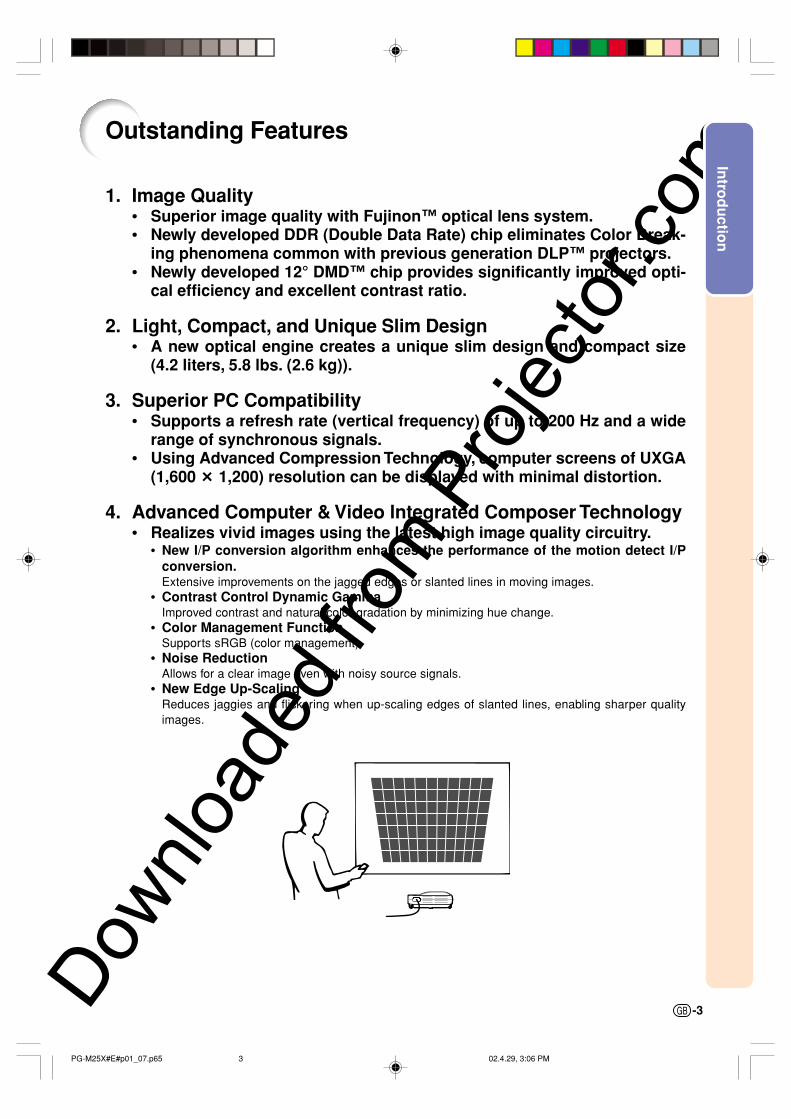
Outstanding Features
1. Image Quality• Superior image quality with Fujinon™ optical lens system.• Newly developed DDR (Double Data Rate) chip eliminates Color Break-
ing phenomena common with previous generation DLP™ projectors.• Newly developed 12° DMD™ chip provides significantly improved opti-
cal efficiency and excellent contrast ratio.
2. Light, Compact, and Unique Slim Design• A new optical engine creates a unique slim design and compact size
(4.2 liters, 5.8 lbs. (2.6 kg)).
3. Superior PC Compatibility• Supports a refresh rate (vertical frequency) of up to 200 Hz and a wide
range of synchronous signals.• Using Advanced Compression Technology, computer screens of UXGA
(1,600 # 1,200) resolution can be displayed with minimal distortion.
4. Advanced Computer & Video lntegrated Composer Technology• Realizes vivid images using the latest high image quality circuitry.
• New I/P conversion algorithm enhances the performance of the motion detect I/Pconversion.Extensive improvements on the jagged edges or slanted lines in moving images.
• Contrast Control Dynamic GammaImproved contrast and natural color gradation by minimizing hue change.
• Color Management FunctionSupports sRGB (color management).
• Noise ReductionAllows for a clear image even with noisy source signals.
• New Edge Up-ScalingReduces jaggies and flickering when up-scaling edges of slanted lines, enabling sharper qualityimages.
PG-M25X#E#p01_07.p65 02.4.29, 3:06 PM3
Downlo
aded
from
Pro
jecto
r.com
-4
6. Built-in PCMCIA card slot (Type II)• Wireless presentations using a wireless LAN PC card.
Supports the global wireless LAN standard, IEEE802.11b.This wireless LAN PC card complies with IEEE802.11b wireless LAN standards.Computers with built-in wireless LAN PC cards that support this standard allow for wirelessconnections.
Note
• A wireless connection with all IEEE802.11b compliant computers is not guaranteed.
The projector or computer can be placed anywhere you want!You can expand your presentation efficiency through a wireless connection, for example, by projectingcomputer images through a projector installed on the ceiling.You can display images from a computer selected from a group of computers.Effective presentations can now be realized without having to reconnect data cables all the time.
• PC-less presentations using a memory card.Just by inserting an IC media (a memory card) such as CompactFlash in the projecter using aPCMCIA card (Type II) adapter, you can make presentations or auto demonstrations without usinga computer.
Note
• For wireless presentations using the wireless LAN PC card, as well as PC-less presentationsusing memory cards, please refer to the Wireless Reality operation manual.
7. GyroRemote• Using the Gyro function, you can realize more effective and advanced
presentations.• The crisp screen pointer gives your presentations a more intuitive touch.• Using the multi-directional wireless remote control, your transmission
range can be expanded, as well as perform the same operations as aUSB mouse on a computer.
PG-M25X#E#p01_07.p65 02.4.29, 3:06 PM4
Downlo
aded
from
Pro
jecto
r.com
Intro
du
ction
-5
Contents
IntroductionOutstanding Features ......................................... 3
Index ................................................................. 125
PG-M25X#E#p01_07.p65 02.4.29, 3:06 PM7
Downlo
aded
from
Pro
jecto
r.com
-8
1. Read InstructionsAll the safety and operating instructions should be readbefore the product is operated.
2. Retain InstructionsThe safety and operating instructions should beretained for future reference.
3. Heed WarningsAll warnings on the product and in the operatinginstructions should be adhered to.
4. Follow InstructionsAll operating and use instructions should be followed.
5. CleaningUnplug this product from the wall outlet before cleaning.Do not use liquid cleaners or aerosol cleaners. Use adamp cloth for cleaning.
6. AttachmentsDo not use attachments not recommended by theproduct manufacturer as they may cause hazards.
7. Water and MoistureDo not use this product near water–for example, neara bath tub, wash bowl, kitchen sink, or laundry tub; in awet basement; or near a swimming pool; and the like.
8. AccessoriesDo not place this product on an unstable cart, stand,tripod, bracket, or table. The product may fall, causingserious injury to a child or adult, and serious damageto the product. Use only with a cart, stand, tripod,bracket, or table recommended by the manufacturer,or sold with the product. Any mounting of the productshould follow the manufacturer’s instructions, andshould use a mounting accessory recommended bythe manufacturer.
9. TransportationA product and cart combinationshould be moved with care. Quickstops, excessive force, anduneven surfaces may cause theproduct and cart combination tooverturn.
10.VentilationSlots and openings in the cabinet are provided forventilation to ensure reliable operation of the productand to protect it from overheating, and these openingsmust not be blocked or covered. The openings shouldnever be blocked by placing the product on a bed,sofa, rug, or other similar surface. This product shouldnot be placed in a built-in installation such as a book-case or rack unless proper ventilation is provided orthe manufacturer’s instructions have been adhered to.
IMPORTANT SAFEGUARDS
11. Power SourcesThis product should be operated only from the type ofpower source indicated on the marking label. If youare not sure of the type of power supply to your home,consult your product dealer or local power company.For products intended to operate from battery power,or other sources, refer to the operating instructions.
12. Grounding or PolarizationThis product is provided with one of the following typesof plugs. If the plug should fail to fit into the power outlet,please contact your electrician.Do not defeat the safety purpose of the plug.
a. Two-wire type (mains) plug.b. Three-wire grounding type (mains) plug with a
grounding terminal.This plug will only fit into a grounding type poweroutlet.
13. Power-Cord ProtectionPower-supply cords should be routed so that they arenot likely to be walked on or pinched by items placedupon or against them, paying particular attention tocords at plugs, convenience receptacles, and the pointwhere they exit from the product.
14. LightningFor added protection for this product during a lightningstorm, or when it is left unattended and unused for longperiods of time, unplug it from the wall outlet anddisconnect the cable system. This will prevent damageto the product due to lightning and power-line surges.
15. OverloadingDo not overload wall outlets, extension cords, or integralconvenience receptacles as this can result in a risk offire or electric shock.
16. Object and Liquid EntryNever push objects of any kind into this product throughopenings as they may touch dangerous voltage pointsor short-out parts that could result in a fire or electricshock. Never spill liquid of any kind on the product.
17. ServicingDo not attempt to service this product yourself asopening or removing covers may expose you to dan-gerous voltage or other hazards. Refer all servicing toqualified service personnel.
CAUTION: Please read all of these instructions before you operate this product and save theseinstructions for later use.
Electrical energy can perform many useful functions. This product has been engineered and manufactured toassure your personal safety. BUT IMPROPER USE CAN RESULT IN POTENTIAL ELECTRICAL SHOCK ORFIRE HAZARDS. In order not to defeat the safeguards incorporated in this product, observe the following basicrules for its installation, use and servicing.
PG-M25X#E#p08_20_a.p65 02.4.29, 4:55 PM8
Downlo
aded
from
Pro
jecto
r.com
Intro
du
ction
-9
18. Damage Requiring ServiceUnplug this product from the wall outlet and referservicing to qualified service personnel under thefollowing conditions:
a. When the power-supply cord or plug is damaged.b. If liquid has been spilled, or objects have fallen
into the product.c. If the product has been exposed to rain or water.d. If the product does not operate normally by
following the operating instructions. Adjust onlythose controls that are covered by the operatinginstructions, as an improper adjustment of othercontrols may result in damage and will oftenrequire extensive work by a qualified technicianto restore the product to normal operation.
e. If the product has been dropped or damaged inany way.
f. When the product exhibits a distinct change inperformance, this indicates a need for service.
19. Replacement PartsWhen replacement parts are required, be sure theservice technician has used replacement partsspecified by the manufacturer or have the samecharacteristics as the original part. Unauthorizedsubstitutions may result in fire, electric shock, or otherhazards.
20. Safety CheckUpon completion of any service or repairs to thisproduct, ask the service technician to perform safetychecks to determine that the product is in properoperating condition.
21. Wall or Ceiling MountingThis product should be mounted to a wall or ceilingonly as recommended by the manufacturer.
22. HeatThis product should be situated away from heat sourcessuch as radiators, heat registers, stoves, or otherproducts (including amplifiers) that produce heat.
PG-M25X#E#p08_20_a.p65 02.4.29, 4:55 PM9
Downlo
aded
from
Pro
jecto
r.com
-10
INTELLECTUAL PROPERTY RIGHTSIMPORTANT
READ BEFORE USING THE PRODUCT
• You have acquired a product that includes software licensed to SHARP Corporation by Lineo, Inc. (“Lineo”).The Software is protected by copyright laws, international copyright treaties, and other intellectual prop-erty laws and treaties. Lineo and its suppliers retain all ownership of, and intellectual property rights in(including copyright), the Software components and all copies thereof, provided however, that certaincomponents of the Software are components licensed under the GNU General Public License (version2), which Lineo supports. You may obtain a copy of the GNU General Public License at http://www.fsf.org/copyleft/gpl.html. Lineo will provide source code for any of the components of the Software licensedunder the GNU General Public License. To obtain such source code, send email to [email protected].
• OS: Embedix (Embedded Linux) Embedix (TM) is a registered trademark of U.S.A. LINEO, Inc.
• DLP™ (Digital Light Processing) and DMD™ (Digital Micromirror Device) are trademarks of Texas Instru-ments, Inc.
• Microsoft and Windows are registered trademarks of Microsoft Corporation, in the United States and/orother countries.
• PC/AT is a registered trademark of International Business Machines Corporation in the United States.• Adobe Acrobat is a trademark of Adobe Systems Incorporated.• Macintosh is a registered trademark of Apple Computer, Inc. in the United States and/or other countries.• All other company or product names are trademarks or registered trademarks of their respective compa-
nies.• Some IC chips in this product include confidential and/or trade secret property belonging to Texas Instru-
ments. Therefore you may not copy, modify, adapt, translate, distribute, reverse engineer, reverse as-semble or discompile the contents thereof.
IMPORTANT SAFEGUARDS (cont.)
PG-M25X#E#p08_20_a.p65 02.4.29, 4:55 PM10
Downlo
aded
from
Pro
jecto
r.com
Intro
du
ction
-11
Be sure to read the following safeguards when setting upyour projector.
Caution concerning the lamp unit Potential hazard of glass
particles if lamp ruptures. Incase of lamp rupture, contactyour nearest Sharp Autho-rized Projector Dealer or Ser-vice Center for a replace-ment.See “Replacing the Lamp” onpage 71.
Cautions concerning the setup of theprojector For minimal servicing and to maintain high
image quality, SHARP recommends that thisprojector be installed in an area free fromhumidity, dust and cigarette smoke. When theprojector is subjected to these environments,the lens must be cleaned more often. As longas the projector is regularly cleaned, use inthese environments will not reduce the overalloperation life of the unit. Internal cleaningshould only be performed by a Sharp Autho-rized Projector Dealer or Service Center.
Do not set up the projector in placesexposed to direct sunlight or brightlight. Position the screen so that it is not in direct
sunlight or room light. Light falling directly onthe screen washes out the colors, makingviewing difficult. Close the curtains and dimthe lights when setting up the screen in asunny or bright room.
The projector may safely be tilted toa maximum angle of 10 degrees. Placement should be
within ±10 degrees.
Do not subject the projector to hardimpact and/or vibration. Take care with the lens so as not to hit or
damage the surface of the lens.
Rest your eyes occasionally. Continuously watching the screen for long
hours will make your eyes tired. Be sure torest your eyes sometimes.
Avoid locations with high or low tem-perature. The operating temperature for the projector
is from 41°F to 95°F (+5°C to +35°C) The storage temperature for the projector is
from –4°F to 140°F (–20°C to +60°C)
Do not block the exhaust and intakevents. Allow at least 11.8 inches (30 cm) of space
between the exhaust vent and the nearestwall or obstruction.
Be sure that the intake vent and the exhaustvent are not obstructed.
If the cooling fan becomes obstructed, a pro-tection circuit will automatically turn off theprojector. This does not indicate a malfunc-tion. Remove the projector power cord fromthe wall outlet and wait at least 10 minutes.Place the projector where the intake andexhaust vents are not blocked, plug the powercord back in and turn on the projector. Thiswill return the projector to the normal oper-ating condition.
Cautions regarding the transporta-tion of the projector When transporting the projector, be sure not
to subject it to hard impact and/or vibration,as this can result in damage. Take extracaution with the lens. Before moving theprojector, be sure to retract the antenna andthe card eject button. Also, be sure to unplugthe power cord from the wall outlet, discon-nect any other cables connected to it andretract the antenna.
CAUTIONPRECAUCI NPR CAUTION
BQC-PGM20X//1
10
10
PG-M25X#E#p08_20_a.p65 02.4.29, 4:56 PM11
Downlo
aded
from
Pro
jecto
r.com
-12
Other connected equipment When connecting a computer or other audio-
visual equipment to the projector, make theconnections AFTER turning off the projectorand the equipment to be connected.
Please read the operation manuals of the pro-jector and the equipment to be connected forinstructions on how to make the connections.
Using the projector in other countries The power supply voltage and the shape of
the plug may vary depending on the regionor country you are using the projector in.When using the projector overseas, be sureto use the appropriate power cord for thecountry you are in.
Temperature monitorfunction If the projector starts to
overheat due to setup prob-lems or blockage of the air vents, “ ” and“ ” will blink in the lower left corner ofthe picture. If the temperature continues torise, the lamp will turn off, the TEMPERA-TURE WARNING indicator on the projectorwill blink, and after a 90-second cooling-offperiod the power will shut off. Refer to “Main-tenance Indicators” on page 70 for details.
Info
• The cooling fan regulates the internal tem-perature, and its performance is automaticallycontrolled. The sound of the fan may changeduring projector operation due to changes inthe fan speed. This does not indicate mal-function.
• Do not unplug the power cord duringprojection or cooling fan operation. This cancreate damage due to the rise in internaltemperature, as the cooling fan also stops.
IMPORTANT SAFEGUARDS (cont.)
PG-M25X#E#p08_20_a.p65 02.4.29, 4:56 PM12
Downlo
aded
from
Pro
jecto
r.com
Intro
du
ction
-13
How to Access the PDF Operation Manuals(Windows, Macintosh)PDF operation manuals in several languages are included in the CD-ROM, so that you canwork with the projector, even if you do not have this manual on hand. To utilize these manuals,you need to install Adobe Acrobat Reader on your PC (Windows or Macintosh). If you havenot installed Acrobat Reader yet, you can install it from the CD-ROM.
To Install Acrobat Reader from the CD-ROMFor Windows:1 Insert the CD-ROM in the CD-ROM drive.2 Double click the “My Computer” icon.3 Double click the “CD-ROM” drive icon.4 Double click the “acrobat” folder.5 Double click the “windows” folder.6 Double click the language (name of the folder)
that you want to view.7 Double click the installation program and follow
the instructions on the screen.
For Macintosh:1 Insert the CD-ROM in the CD-ROM drive.2 Double click the “CD-ROM” icon.3 Double click the “acrobat” icon.4 Double click the language (name of the folder)
that you want to view.5 Double click the desired installation program
and follow the instructions on the screen.
For other operating systems:Please download Acrobat Reader from the Internet (http://www.adobe.com)
For other languages:If you prefer using Acrobat Reader for languages other than those included in the CD-ROM, pleasedownload the appropriate version from the Internet.
Accessing the PDF ManualsFor Windows:1 Insert the CD-ROM in the CD-ROM drive.2 Double click the “My Computer” icon.3 Double click the “CD-ROM” drive.4 Double click the “manuals” folder.5 Double click the language (name of the folder)
that you want to view.6 Double click the “m25x” pdf file to access the
projector manuals.Double click the “soft” pdf file to access theWireless Reality.Double click the “WC11b” pdf file to access theWireless LAN PC Card manual.
For Macintosh:1 Insert the CD-ROM in the CD-ROM drive.2 Double click the “CD-ROM” icon.3 Double click the “manuals” folder.4 Double click the language (name of folder) that
you want to view.5 Double click the “m25x” pdf file to access the
projector manuals.
Note
• If the desired pdf file cannot be opened by double clicking the mouse, start Acrobat Reader first, then specifythe desired file using the “File”, “Open” menu.
• See the “readme.txt” file on the CD-ROM for important information not included in this operation manual.
PG-M25X#E#p08_20_a.p65 02.4.29, 4:56 PM13
Downlo
aded
from
Pro
jecto
r.com
-14
Projector (Front and Top View)
Part Names
Numbers in refer to the main pages in this Operation Manual where the topic is explained.
110
110110
34
38
50
50
35
37
35
50
35
51
63
22
35
14
18
37
40
Foot releases/AdjustmentfeetFor adjusting the projector’sheight. Attaching the terminal cover
Attach the terminal cover by
placing it on the side panel of the
projector and pressing it into
place, as shown in the illustration.
TEMPERATUREwarning indicatorIlluminates in greennormally. When theinternal temperaturerises, this indicator willilluminate in red.
Zoom knob
Focus ring
AV MUTE buttonFor temporarily turning off thesound and picture.
ENTER buttonFor setting items selected oradjusted on the menu.
Adjustment buttons("'\ |"'\ |"'\ |"'\ |"'\ |)For selecting menu items.
POWER indicatorIlluminates in red, when theprojector is in standby. Whenthe power is turned on, thisindicator will illuminate ingreen.
LAMP replacementindicatorIlluminates in green normally.Replace the lamp when theindicator illuminates in red.
AUTO SYNC buttonFor automaticallyadjusting images whenconnected to a computer.
UNDO buttonFor undoing an operationor returning to the defaultsettings.
VOLUME buttonsFor adjusting the speakersound level.
MENU buttonFor displaying adjustmentand setting screens.
INPUT buttonFor switching input mode1, 2, 3 or 4.
Remote controlsensor
Terminal cover
Speaker
GyroRemoteAntenna
PG-M25X#E#p08_20_a.p65 02.4.29, 4:56 PM14
Downlo
aded
from
Pro
jecto
r.com
Intro
du
ction
-15
47
48
31
30
27
30
26
11
15
27
Projector (Side View)
Exhaust vent
AC socket
Kensington SecurityStandard connector
Using the Kensington Lock• This projector has a Kensington Security Standard connector for use with a Kensington MicroSaver Security
System. Refer to the information that came with the system for instructions on how to use it to secure theprojector.
Attaching the lens capAfter putting the lens cap strap on the lens cap, passthe other end of the strap through the hole under theprojector, next to the lens, as shown in the illustration.
Bottom View
INPUT 2 terminalTerminal for connecting videoequipment with an S-VIDEOterminal.
INPUT 1 terminalPort for DVI digital, computerRGB, and COMPONENTsignals.
INPUT 4 terminalFor inserting a wirelessLAN PC card or a memorycard.
PG-M25X#E#p08_20_a.p65 02.4.29, 4:56 PM15
Downlo
aded
from
Pro
jecto
r.com
-16
GyroRemote
Part Names (cont.)
Gyration U.S. Patents5698784, 5825350, 5898421
WIRE R/C JACK
42
44
54
35
41
42
40
35
48
49
38
42
40
48
44
Bottom
48
Front
Rear
Function 1 / 2 buttonsFor specifying the button assignmentsfor Function 1 and Function 2
INPUT buttonFor switching between inputs 1,2,3and 4.
L-CLICK/ ENTER buttonFor entering menu items or to performa left click when using thewireless mouse.
POWER buttonFor turning the power on or off.
LENS buttonFor adjusting Keystone or Digital Shiftsetting.
Function 3 / 4 buttonsFor specifying the button assignmentsfor Function 3 and Function 4
LED indicatorLights up when the GyroRemote is inmotion.
POINTER buttonHolding this button down displays apointer on the screen.
R-CLICK / UNDO buttonFor undoing an operation or toperform a right click when using thewireless mouse.
MENU buttonFor displaying adjustment andsetting screens.
VOLUME buttonsFor adjusting the speaker soundlevel.
ASSIGN buttonSwitches the button assignmentfunction group.
RF CH+ buttonFor checking the current RF channelas well as switching the channel.
GYRO ACTIVEFor moving the Gyrofunction for actions suchas moving tool icons(such as stamp), selectingmenus in the OSD, ormoving the cursor usingthe wireless mouse.
Wired remoteterminal(ø2.5 mmminijack)
TEACH (OK) buttonFor registering the GyroRemote in theprojector.
PG-M25X#E#p08_20_a.p65 02.4.29, 4:56 PM16
Downlo
aded
from
Pro
jecto
r.com
Intro
du
ction
-17
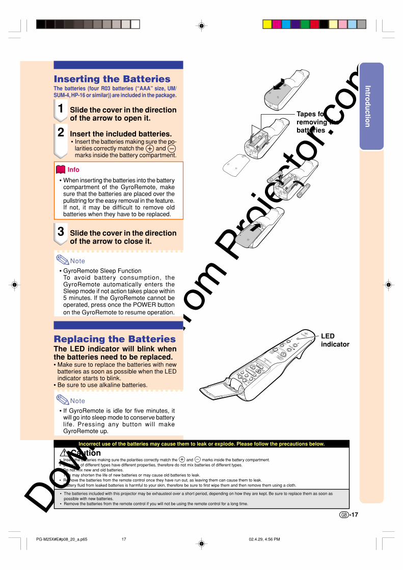
Incorrect use of the batteries may cause them to leak or explode. Please follow the precautions below.
Tapes forremoving thebatteries
Inserting the BatteriesThe batteries (four R03 batteries (“AAA” size, UM/SUM-4, HP-16 or similar)) are included in the package.
1 Slide the cover in the directionof the arrow to open it.
2 Insert the included batteries.• Insert the batteries making sure the po-
larities correctly match the and marks inside the battery compartment.
Info
• When inserting the batteries into the batterycompartment of the GyroRemote, makesure that the batteries are placed over thepullstring for the easy removal in the feature.If not, it may be difficult to remove oldbatteries when they have to be replaced.
3 Slide the cover in the directionof the arrow to close it.
Note
• GyroRemote Sleep FunctionTo avoid battery consumption, theGyroRemote automatically enters theSleep mode if not action takes place within5 minutes. If the GyroRemote cannot beoperated, press once the POWER buttonon the GyroRemote to resume operation.
Replacing the BatteriesThe LED indicator will blink whenthe batteries need to be replaced.• Make sure to replace the batteries with new
batteries as soon as possible when the LEDindicator starts to blink.
• Be sure to use alkaline batteries.
Note
• If GyroRemote is idle for five minutes, itwill go into sleep mode to conserve batterylife. Pressing any button will makeGyroRemote up.
LEDindicator
Caution• Insert the batteries making sure the polarities correctly match the and marks inside the battery compartment.• Batteries of different types have different properties, therefore do not mix batteries of different types.• Do not mix new and old batteries.
This may shorten the life of new batteries or may cause old batteries to leak.• Remove the batteries from the remote control once they have run out, as leaving them can cause them to leak.
Battery fluid from leaked batteries is harmful to your skin, therefore be sure to first wipe them and then remove them using a cloth.
• The batteries included with this projector may be exhausteol over a short period, depending on how they are kept. Be sure to replace them as soon aspossible with new batteries.
• Remove the batteries from the remote control if you will not be using the remote control for a long time.
PG-M25X#E#p08_20_a.p65 02.4.29, 4:56 PM17
Downlo
aded
from
Pro
jecto
r.com
-18
GyroRemote FeaturesThis projector uses the GyroRemote technology, that allows for the following features when compared toordinary infrared remote controls.
RF TechnologyWith ordinary remote controls, the operation range is limitedbecause of directivity; they cannot operate if there are objectsbetween the projector and the remote.The GyroRemote can operate up to a range of 15 m (49.2 feet) bysending RF signals to the projector.
Note
• The control range measured is with the projector’s antenna fully extended.• The control range under actual operating conditions may be less than optimum depending on where the
projector is placed.
Caution
Do not use the GyroRemote in restricted places, such as hospitals.• Signals from the GyroRemote may affect electronic equipment or medical electronic equipment, thereby
causing accidents.• When using the GyroRemote in medical institutions, make sure to follow the directives of each institution.
Multi-Projector ControlThis projector has a GyroRemote identification function that makes possible to perform various operationssuch as the ones below.
No interference even if other projectors of the same type are within the GyroRemote’s operating range.
Multiple projectors can be operated with one GyroRemote.
One projector can be operated using multiple GyroRemotes.
• Refer to page 40 for details about using the GyroRemote.
The GyroRemote
Operation Range: Area up to a 15 m
PG-M25X#E#p08_20_a.p65 02.4.29, 4:56 PM18
Downlo
aded
from
Pro
jecto
r.com
Intro
du
ction
-19
Calibrating theGyroRemoteIf there are any extreme temperature changeswhen the GyroRemote is being used or afterbatteries have been replaced, the mousecursor or pointer may continue to move byitself even if no action has been performed. Inthis case, calibrate the GyroRemote using thefollowing procedure.
1 Double click on the rearof the GyroRemote.
2 Make sure that the LEDindicator is lit, and place theGyroRemote on a leveledlocation.• After leaving the GyroRemote for 6
seconds, the calibration of theGyroRemote is complete.
3 Press , after leaving theGyroRemote for more than 6seconds.• Calibration is complete after the
remote has been left for more than 6seconds.
GYRO ACTIVEbutton
PG-M25X#E#p08_20_a.p65 02.4.29, 4:56 PM19
Downlo
aded
from
Pro
jecto
r.com
-20
Note
Accessories
GyroRemote(1) For U.S., Canada, etc.
RRMCG1631CESA(2) For Europe, Australia, Oceania and Asia
RRMCG1653CESA
Four R03 batteries(“AAA” size, UM/SUM-4,HP-16 or similar)
Power cord (6' (1.8m))
For U.S., Canada, etc.QACCDA007WJPZ
For Europe, except U.K.QACCV4002CEZZ
For U.K., Hong Kongand SingaporeQACCB5024CENA
For Australia, NewZealand and OceaniaQACCL3022CEZZ
• Depending on the region, projectors only ship with one power cord (see above). Use the power cord thatcorresponds to the wall outlet in your country.
• If you cannot connect after changing computer ports, be sure to check you computer’s specifications.If you are still having difficulty connecting, a conversion connector (commercially available) may be necessary.
Wireless LAN PC card AN-WC11B
Note • All cables may not be available in all regions. Please check with your nearest Sharp AuthorizedProjector Dealer or Service Center.
CD-ROMUDSKA001WJZZ
Operation manual(this manual)
Quick reference guidesWireless Reality operation manualWireless LAN PC card precautions
(1) (2) (3) (4)
Two Wireless LAN PC cardsAN-WC11B(RUNTKA025WJZZ)
PG-M25X#E#p08_20_a.p65 02.4.29, 4:56 PM20
Downlo
aded
from
Pro
jecto
r.com
Setu
p an
d C
on
nectio
ns
Setup and Connections
PG-M25X#E#p21_32.p65 02.4.29, 3:09 PM21
Downlo
aded
from
Pro
jecto
r.com
Up Down
Foot releases
Adjustment feet
Setup
Using the AdjustmentFeetThe height of the projector can be adjustedusing the adjustment feet when the surfaceof the projector is placed on is uneven or whenthe screen is slanted.The projection of the image can be madehigher by adjusting the projector when it is ina location lower than the screen.
1 Press the foot releases.
2 Lift the projector to adjust itsheight and remove your handsfrom the foot releases.
3 Rotate the adjustment feet tomake minor changes.
Note
• When returning the projector to its origi-nal position, hold the projector firmly, pressthe foot releases and then lower it.
• The projector is adjustable up to approxi-mately 5.5 degrees from the standard po-sition.
Info
• Do not press the foot releases when thefeet are extended without firmly holdingthe projector.
• Do not hold the lens when lifting or lower-ing the projector.
• When lowering the projector, be careful notto get your fingers caught in the area be-tween the adjustment feet and the projector.
-22
PG-M25X#E#p21_32.p65 02.4.29, 3:09 PM22
Downlo
aded
from
Pro
jecto
r.com
Setu
p an
d C
on
nectio
ns
-23
90°
90°
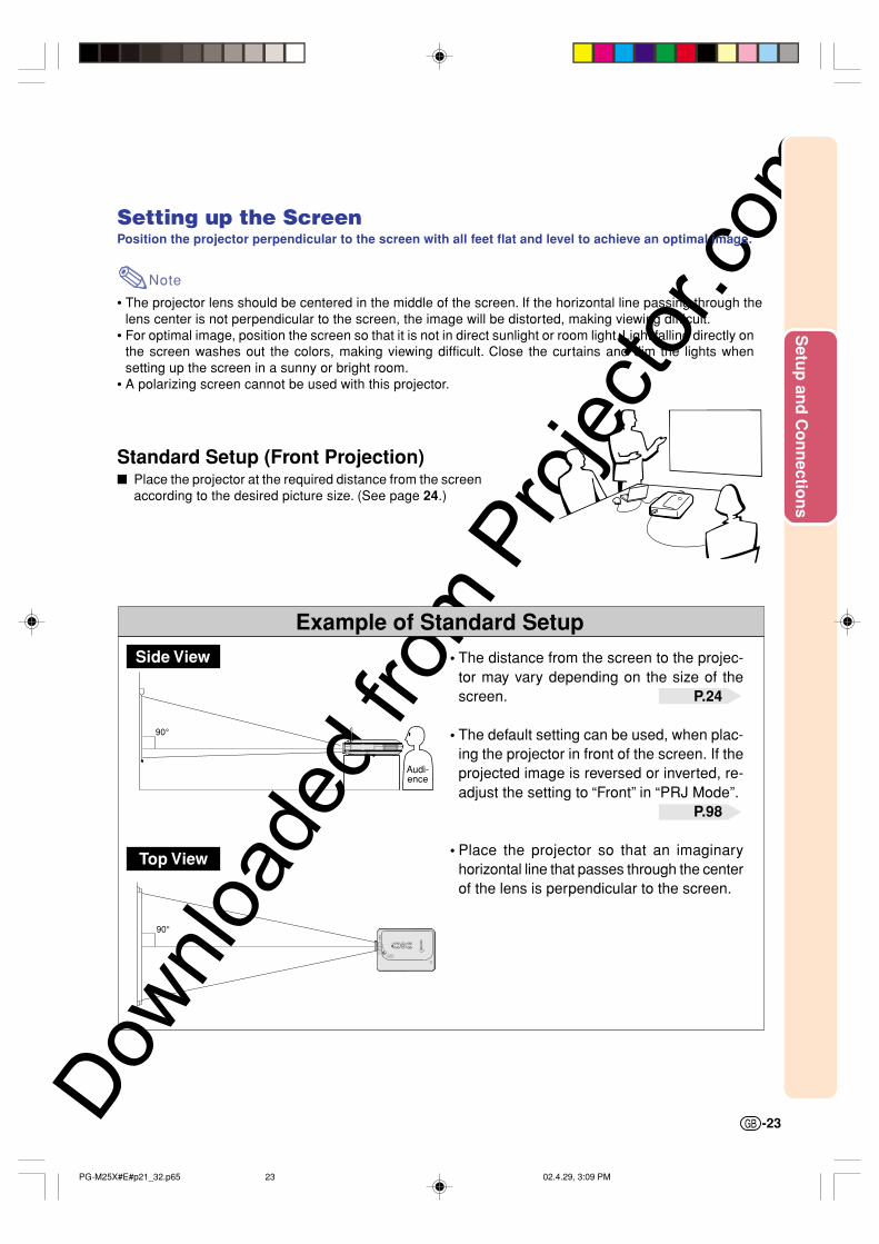
Example of Standard Setup
Setting up the ScreenPosition the projector perpendicular to the screen with all feet flat and level to achieve an optimal image.
Note
• The projector lens should be centered in the middle of the screen. If the horizontal line passing through thelens center is not perpendicular to the screen, the image will be distorted, making viewing difficult.
• For optimal image, position the screen so that it is not in direct sunlight or room light. Light falling directly onthe screen washes out the colors, making viewing difficult. Close the curtains and dim the lights whensetting up the screen in a sunny or bright room.
• A polarizing screen cannot be used with this projector.
Standard Setup (Front Projection) Place the projector at the required distance from the screen
according to the desired picture size. (See page 24.)
Side View
Top View
• The distance from the screen to the projec-tor may vary depending on the size of thescreen. P.24
• The default setting can be used, when plac-ing the projector in front of the screen. If theprojected image is reversed or inverted, re-adjust the setting to “Front” in “PRJ Mode”.
P.98
• Place the projector so that an imaginaryhorizontal line that passes through the centerof the lens is perpendicular to the screen.
Audi-ence
PG-M25X#E#p21_32.p65 02.4.29, 3:09 PM23
Downlo
aded
from
Pro
jecto
r.com
-24
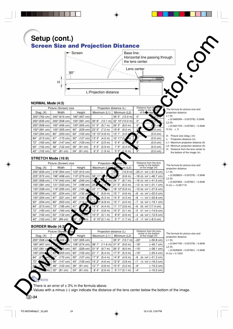
Setup (cont.)Screen Size and Projection Distance
90°
H
Screen Base line:Horizontal line passing throughthe lens center.
Lens center
L:Projection distance
The formula for picture size andprojection distanceL1 (ft)
= (0.048539X – 0.037278) / 0.3048L2 (ft)
= (0.040172X – 0.037561) / 0.3048H (in) = 0
X: Picture size (diag.) (in)L: Projection distance (m)L1: Maximum projection distance (ft)L2: Minimum projection distance (ft)H: Distance from the lens center to
the bottom of the image (in)
The formula for picture size andprojection distanceL1 (ft)
The formula for picture size andprojection distanceL1 (ft)
= (0.064719X – 0.037278) / 0.3048L2 (ft)
= (0.053563X – 0.037561) / 0.3048H (in) = 0.100X
Note
• There is an error of ± 3% in the formula above.• Values with a minus (–) sign indicate the distance of the lens center below the bottom of the image.
NORMAL Mode (4:3)Picture (Screen) size Projection distance (L)
60" (152 cm) 48" (122 cm) 36" (91 cm) 12' 7" (3.8 m) 10' 5" (3.2 m) –6" (–15.2 cm)
40" (102 cm) 32" (81 cm) 24" (61 cm) 8' 4" (2.6 m) 6' 11"(2.1 m) –4" (–10.2 cm)
Distance from the lenscenter to the bottom
of the image (H)
Distance from the lenscenter to the bottom
of the image (H)
Distance from the lenscenter to the bottom
of the image (H)
PG-M25X#E#p21_32.p65 02.4.29, 3:09 PM24
Downlo
aded
from
Pro
jecto
r.com
Setu
p an
d C
on
nectio
ns
-25
When using the default setting.On-screen Display
Projecting a Reversed/Inverted Image
Projection from behind the screen Place a translucent screen between the projector and the
audience. Reverse the image by setting “Rear” in “PRJ Mode”. See
page 98 for use of this function.
Projection using a mirror Place a mirror (normal flat type) in front of the lens. Reverse the image by setting “Rear” in “PRJ Mode”, when the
mirror is placed on the audience side. See page 98 for use ofthis function.
Info
• When using a mirror, be sure to carefully position both the pro-jector and the mirror so the light does not shine into the eyes ofthe audience.
Ceiling-mount setup It is recommended that you use the optional Sharp ceiling-mount
bracket for this installation.Before mounting the projector, contact your nearest SharpAuthorized Projector Dealer or Service Center to obtain therecommended ceiling-mount bracket (sold separately.) (AN-PGCM90 ceiling-mount bracket, its AN-EP101B extension tubeand AN-JT200 universal bracket, adaptor for non-level ceilinginstallation (for U.S.A.), BB-M20T ceiling adaptor, its BB-NVHOLDER280, BB-NVHOLDER550, BB-NVHOLDER900ceiling mount systems (for GERMANY), or AN-60KT ceiling-mount bracket, its AN-TK301/AN-TK201 and AN-TK302/AN-TK202 extension tubes (for countries other than the U.S.A. andGERMANY))
Be sure to adjust the position of the pro-jector to match the distance (H) fromthe lens center position (see page 24)to the lower edge of the image, whenmounting the projector onthe ceiling.
Invert the image bysetting “Ceiling + Front”in “PRJ Mode”.
The image is reversed.
When using the default setting.On-screen Display
The image is reversed.
When using the default setting.On-screen Display
The image is inverted.
PG-M25X#E#p21_32.p65 02.4.29, 3:09 PM25
Downlo
aded
from
Pro
jecto
r.com
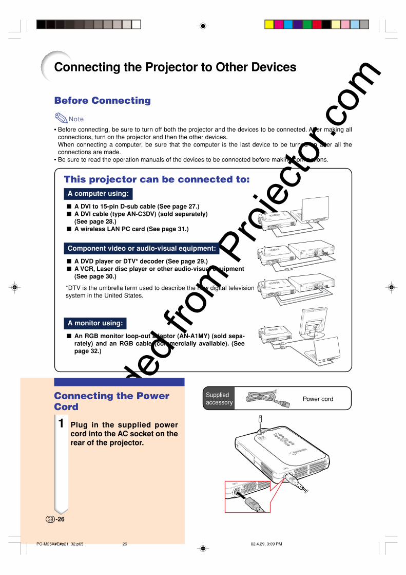
Connecting the Projector to Other Devices
Before Connecting
Note
• Before connecting, be sure to turn off both the projector and the devices to be connected. After making allconnections, turn on the projector and then the other devices.When connecting a computer, be sure that the computer is the last device to be turned on after all theconnections are made.
• Be sure to read the operation manuals of the devices to be connected before making connections.
This projector can be connected to:A computer using:
A DVI to 15-pin D-sub cable (See page 27.) A DVI cable (type AN-C3DV) (sold separately)
(See page 28.) A wireless LAN PC card (See page 31.)
Component video or audio-visual equipment:
A DVD player or DTV* decoder (See page 29.) A VCR, Laser disc player or other audio-visual equipment
(See page 30.)
*DTV is the umbrella term used to describe the new digital televisionsystem in the United States.
A monitor using:
An RGB monitor loop-out adaptor (AN-A1MY) (sold sepa-rately) and an RGB cable (commercially available). (Seepage 32.)
Suppliedaccessory Power cordConnecting the Power
Cord
1 Plug in the supplied powercord into the AC socket on therear of the projector.
-26
PG-M25X#E#p21_32.p65 02.4.29, 3:09 PM26
Downlo
aded
from
Pro
jecto
r.com
Setu
p an
d C
on
nectio
ns
-27
1DVI to 15-pin D-sub cable
Connecting the Projector to a Computer
Connecting to a ComputerUsing the DVI to 15-pinD-sub Cable
1 Connect the projector to thecomputer using the suppliedDVI to 15-pin D-sub cable.• Secure the connectors by tightening
the thumbscrews.
2 To input audio signal, connectthe projector to the computerusing a ø3.5 mm stereo audiocable (commercially availableor available as Sharp servicepart QCNW-4870CEZZ).
Note
• See page 115 “Computer CompatibilityChart” for a list of computer signals com-patible with the projector. Use with com-puter signals other than those listed maycause some of the functions not to work.
• When connecting the projector to a com-puter in this way, select “RGB” for “SignalType” in the “Picture” menu. See page 60.
• A Macintosh adaptor may be required foruse with some Macintosh computers. Con-tact your nearest Sharp AuthorizedProjector Dealer or Service Center.
Connecting the thumbscrew cables Connect the thumbscrew cable making sure that it
fits correctly into the port. Then, firmly secure theconnectors by tightening the screws on both sidesof the plug.
Do not remove the ferrite core attached to the DVIto 15-pin D-sub cable.
Ferrite core
Suppliedaccessory
DVI to 15-pinD-sub cable
To RGB Output port
To Audio Output port
Notebook computer
2ø3.5 mm stereo audiocable (commerciallyavailable or available asSharp service partQCNW-4870CEZZ)
PG-M25X#E#p21_32.p65 02.4.29, 3:09 PM27
Downlo
aded
from
Pro
jecto
r.com
-28
1DVI cable(sold separately)
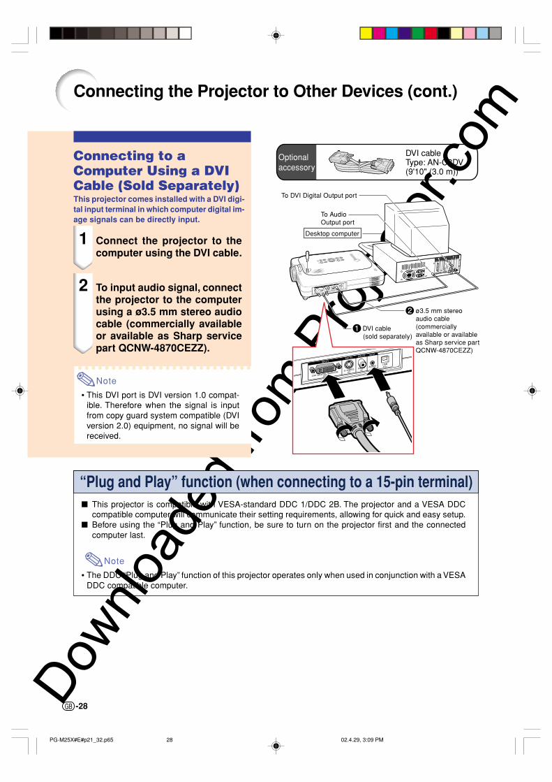
Connecting the Projector to Other Devices (cont.)
Connecting to aComputer Using a DVICable (Sold Separately)This projector comes installed with a DVI digi-tal input terminal in which computer digital im-age signals can be directly input.
1 Connect the projector to thecomputer using the DVI cable.
2 To input audio signal, connectthe projector to the computerusing a ø3.5 mm stereo audiocable (commercially availableor available as Sharp servicepart QCNW-4870CEZZ).
Note
• This DVI port is DVI version 1.0 compat-ible. Therefore when the signal is inputfrom copy guard system compatible (DVIversion 2.0) equipment, no signal will bereceived.
“Plug and Play” function (when connecting to a 15-pin terminal) This projector is compatible with VESA-standard DDC 1/DDC 2B. The projector and a VESA DDC
compatible computer will communicate their setting requirements, allowing for quick and easy setup. Before using the “Plug and Play” function, be sure to turn on the projector first and the connected
computer last.
Note
• The DDC “Plug and Play” function of this projector operates only when used in conjunction with a VESADDC compatible computer.
Optionalaccessory
DVI cableType: AN-C3DV(9'10" (3.0 m))
To DVI Digital Output port
To AudioOutput port
2ø3.5 mm stereoaudio cable(commerciallyavailable or availableas Sharp service partQCNW-4870CEZZ)
Desktop computer
PG-M25X#E#p21_32.p65 02.4.29, 3:09 PM28
Downlo
aded
from
Pro
jecto
r.com
Setu
p an
d C
on
nectio
ns
-29
1DVI to 15-pinD-sub adaptor(sold separately)
Connecting to Video Equipment
Connecting toComponent VideoEquipmentUse a 3 RCA to 15-pin D-sub cable and DVI to15-pin D-sub adaptor when connecting to theINPUT 1 terminal, component video equipmentsuch as DVD players and DTV* decoders.
*DTV is the umbrella term used to describethe new digital television system in the UnitedStates.
1 Connect the 3 RCA to 15-pin D-sub cable using the DVI to 15-pin D-sub adaptor.
2 Use the above cables to con-nect the projector and thevideo equipment.
3 Connect the projector and thevideo equipment using a ø3.5mm to RCA audio cable(commercially available).
Note
• When connecting the projector to thevideo equipment in this way, select “Com-ponent” for “Signal Type” in the “Picture”menu. See page 60.
• A ø3.5 mm stereo minijack to RCA audiocable (commercially available) is requiredfor audio input.
Optionalaccessories
3RCA to 15-pinD-sub cableType: AN-C3CP(9'10" (3.0 m))
DVI to 15-pinD-sub adaptorModel: AN-A1DV(7.9" (20 cm))
To analog componentoutput terminal
To audio output terminal
DVD player orDTV* decoder3ø3.5 mm to RCA audio
cable (commerciallyavailable)
2 3 RCA to 15-pinD-sub cable(sold separately)
PG-M25X#E#p21_32.p65 02.4.29, 3:10 PM29
Downlo
aded
from
Pro
jecto
r.com
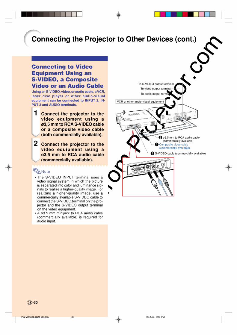
1S-VIDEO cable (commercially available)
Connecting to VideoEquipment Using anS-VIDEO, a CompositeVideo or an Audio CableUsing an S-VIDEO, video, or audio cable, a VCR,laser disc player or other audio-visualequipment can be connected to INPUT 2, IN-PUT 3 and AUDIO terminals.
1 Connect the projector to thevideo equipment using aø3,5 mm to RCA S-VIDEO cableor a composite video cable(both commercially available).
2 Connect the projector to thevideo equipment using aø3.5 mm to RCA audio cable(commercially available).
Note
• The S-VIDEO INPUT terminal uses avideo signal system in which the pictureis separated into color and luminance sig-nals to realize a higher-quality image. Forrealizing a higher-quality image, use acommercially available S-VIDEO cable toconnect the S-VIDEO terminal on the pro-jector and the S-VIDEO output terminalon the video equipment.
• A ø3.5 mm minijack to RCA audio cable(commercially available) is required foraudio input.
To S-VIDEO output terminal
To video output terminal
To audio output terminal
VCR or other audio-visual equipment
2ø3.5 mm to RCA audio cable(commercially available)
1Composite video cable(commercially available)
Connecting the Projector to Other Devices (cont.)
-30
PG-M25X#E#p21_32.p65 02.4.29, 3:10 PM30
Downlo
aded
from
Pro
jecto
r.com
Setu
p an
d C
on
nectio
ns
-31
Installing / Removing the PC Card
Remove the cardfrom the slot andstore it in a safeplace. If the Ejectbutton is out, pressit once more to setit back in place.
Eject button
The notch
Make sure that the Ejectbutton is not out, and thatthe notch on the card is tothe left, when installing thecard.Take care when installingthe card, as it has both atop part and an under part.
Eject button
1Press the Eject button.The Eject button pops out.
Press. Pops out.
2Press the Eject buttonagain. The PC Card willprotrude from the card sloton the computer.
The cardcomes out a
little.
Press.
Installing the PC Cardin to INPUT 4 TerminalInsert a PC card such as a wireless LAN cardor memory card as shown on the right.
Info
• We recommend that you recess the Ejectbutton before inserting the PC card.This will prevent accidental ejection duringoperation.
• The input mode will change automatically toINPUT 4, when the PC card has beeninserted into INPUT 4 terminal.
Removing the PC Card
1 In the Card menu, select “EjectPC Card”. For details see page68.
2 Remove the card.
Note
• To prevent unstable operation, it is rec-ommended that you use the EJECT PCCARD function in PC CARD menu beforeremoving the PC card.
PG-M25X#E#p21_32.p65 02.4.29, 3:10 PM31
Downlo
aded
from
Pro
jecto
r.com
To RGB output port
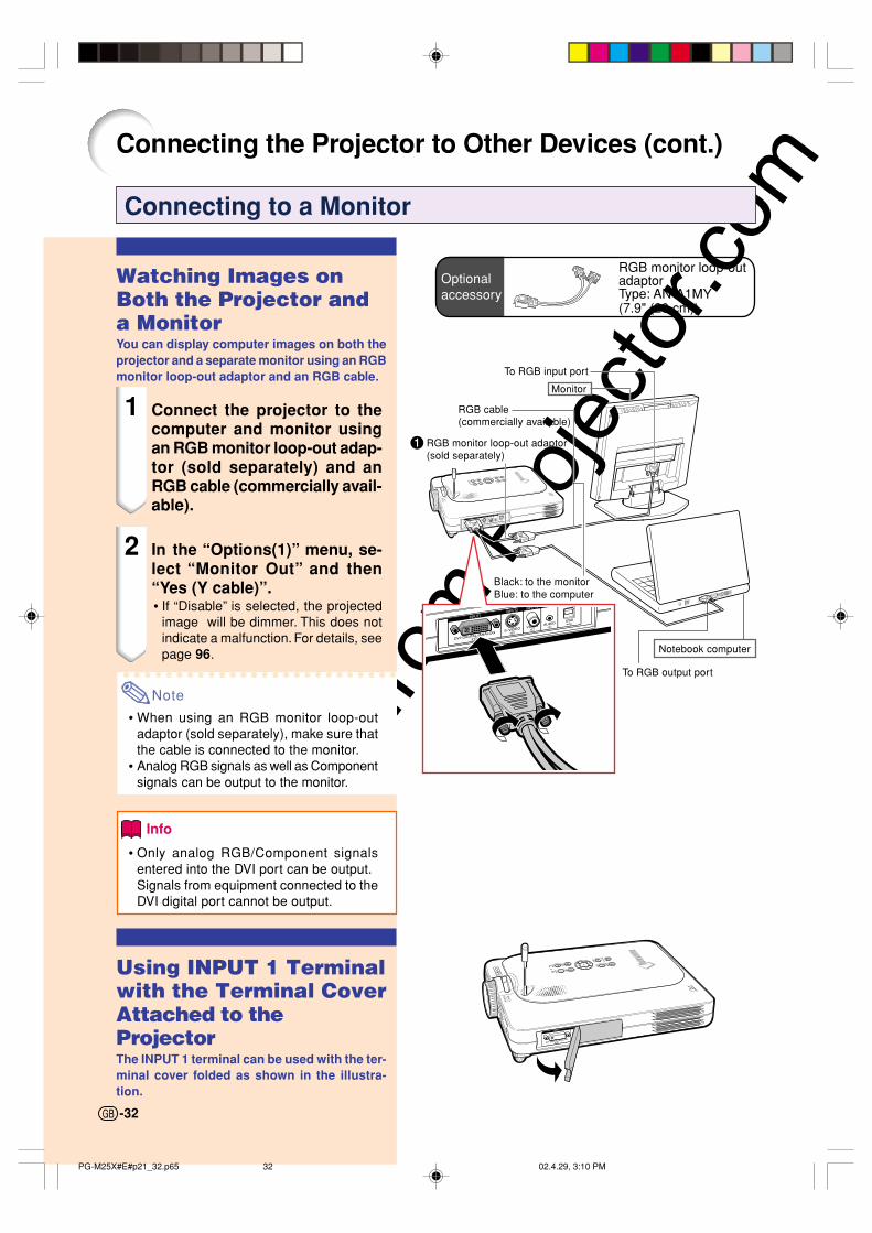
Connecting to a Monitor
Watching Images onBoth the Projector anda MonitorYou can display computer images on both theprojector and a separate monitor using an RGBmonitor loop-out adaptor and an RGB cable.
1 Connect the projector to thecomputer and monitor usingan RGB monitor loop-out adap-tor (sold separately) and anRGB cable (commercially avail-able).
2 In the “Options(1)” menu, se-lect “Monitor Out” and then“Yes (Y cable)”.• If “Disable” is selected, the projected
image will be dimmer. This does notindicate a malfunction. For details, seepage 96.
Note
• When using an RGB monitor loop-outadaptor (sold separately), make sure thatthe cable is connected to the monitor.
• Analog RGB signals as well as Componentsignals can be output to the monitor.
Info
• Only analog RGB/Component signalsentered into the DVI port can be output.Signals from equipment connected to theDVI digital port cannot be output.
Using INPUT 1 Terminalwith the Terminal CoverAttached to theProjectorThe INPUT 1 terminal can be used with the ter-minal cover folded as shown in the illustra-tion.
Basic ProcedureConnect the required external equipment to theprojector before operating the following procedures.Details are found in the projector operationmanual.
Info
• The language preset at the factory is English.If you want to change the on-screen displayto another language, reset the language ac-cording to the procedure on page 37.
1 Plug the power cord into the wall outlet.• The POWER indicator illuminates up in red,
and the projector enters standby mode.
2 Press on the projector or on the GyroRemote.
• The POWER indicator illuminates ingreen. After the LAMP REPLACEMENTindicator illuminates, the projector isready to start operation.
Note
• The LAMP REPLACEMENT indica-tor illuminates, indicating the statusof the lamp.Green: The lamp is ready.Green blinking: The lamp is
warming up.Red: The lamp should be replaced.
• If the power is turned off andimmediately switched on again, theLAMP REPLACEMENT indicator maytake time to illuminate.
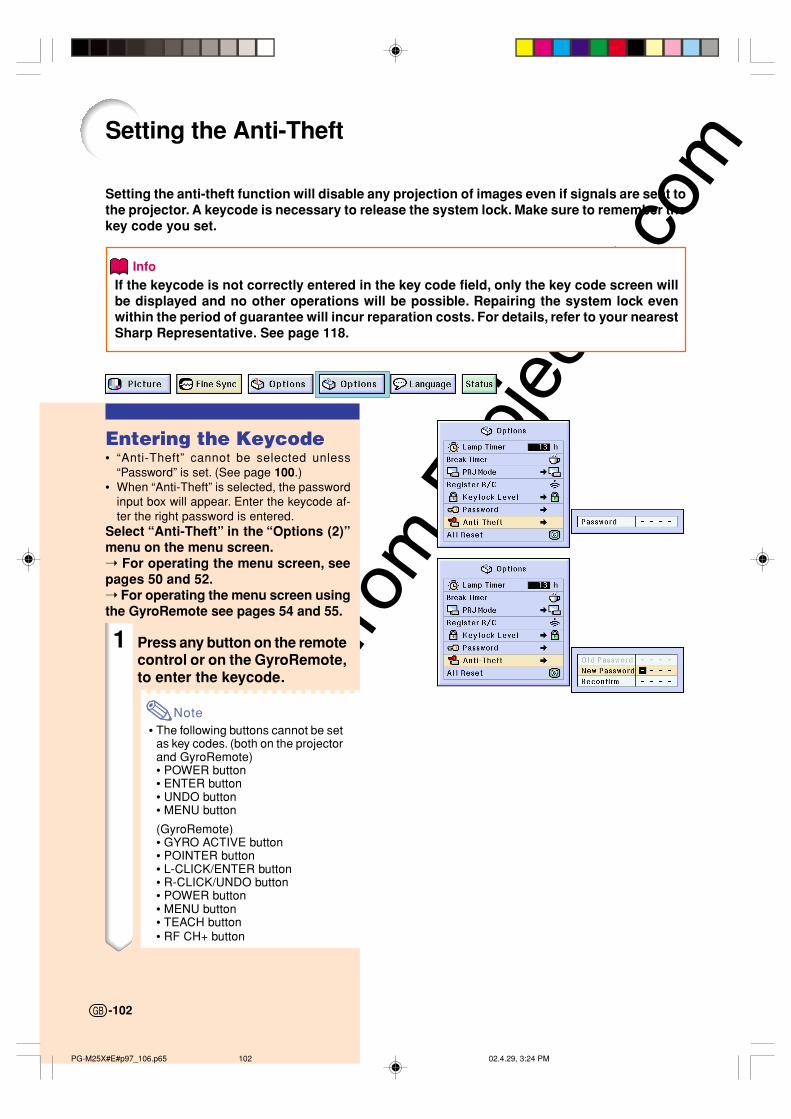
When “Anti-Theft” (see page 102) isset, the keycode input box will appear.• Enter the keycode.
Note
• When entering the keycode, pressthe buttons previously set on theprojector or the GyroRemote.
Info
• When “Anti-Theft” is set, enter thekeycode or the input display will not ap-pear. Even when the signal is input, thedisplay will not appear. (See page 102.)
Projector indicators
LAMP REPLACEMENT indicatorPOWER indicator
POWER button INPUTbutton
INPUT button
POWER button
Keycode input box
-34
Volumebuttons
AV MUTEbutton
Volume button
PG-M25X#E#p33_49.p65 02.4.29, 3:11 PM34
Downlo
aded
from
Pro
jecto
r.com
Basic O
peratio
n
-35
"On-screen Display (Example)
UsingAnalog RGB
UsingComponent
INPUT 2 Mode
INPUT 3 Mode
4 Press and select the inputmode.• Each press switches in the following
order’ INPUT 1 INPUT 2 INPUT 3 INPUT 4
• You can also use the on theGyroRemote.
Note
• When no signal is received, “NOSIGNAL” will be displayed. When asignal that the projector is not pre-set to receive is received, “NOTREG.” will be displayed.
• When Auto Search is ON, the inputmodes with signals can be selected(See page 91.)
• When a PC card is inserted, theinput will automatically change toINPUT 4.
• You can select the input modedirectly by using the Button Assignfunction on the GyroRemote (Seepage 41.)
About the INPUT ModesUsed for projecting im-ages from equipment thatsends RGB signals orComponent signals con-nected to the DVI-DIGI-TAL/ANALOG input port.Used for projecting im-ages from equipmentconnected to the S-VIDEO input terminal.Used for projecting im-ages from equipmentconnected to the VIDEOinput terminal.When projecting from awireless LAN PC card ora memory card.
INPUT 1(RGB/Component)
INPUT 2(S-Video)
INPUT 3(Video)
INPUT 4(PC Card)
INPUT 1 Mode
5 Press or on the Gyro-Re-mote to adjust the volume.
Note
• Pressing will raise the volume.
Pressing will lower the volume.
• On the GyroRemote, the volume canbe adjusted by pressing .
• When a PC card is installed, ,
on the projector or on theGyroRemote operate as cursorbuttons (\, |) when the OSD menuis active.
UsingDVI digital
Using S-Video
Using Video
INPUT 4 Mode
PC Card installed
PG-M25X#E#p33_49.p65 02.4.29, 3:11 PM35
Downlo
aded
from
Pro
jecto
r.com
Image Projection (cont.)
6 Press on the projector totemporarily turn off the pictureand sound.
Note
• Pressing again will turn the pic-ture and the sound back on.
• When using the GyroRemote, youcan select AV MUTE using theButton Assign function (seepage 41.)
• If you want to temporarily mute thesound, select MUTE using theButton Assign function (seepage 41.)
7 Press on the projector or on the GyroRemote.
When the confirmation screenis displayed, press or
once again.
Note
• If you accidentally pressed anddo not want to turn off the power,wait until the confirmation messagedisappears.
Info
• Do not unplug the power cord dur-ing projection or cooling fan opera-tion. This can cause damage due tothe rise in internal temperature, asthe cooling fan also stops.
• When connected to equipment suchas an amplifier, be sure to turn offthe power to the equipment con-nected first and then to the projector.
-36
PG-M25X#E#p33_49.p65 02.4.29, 3:11 PM36
Downlo
aded
from
Pro
jecto
r.com
Basic O
peratio
n
-37
Zoom inZoom out
Selecting the On-screenDisplay Language
• The on-screen display language of the pro-jector can be set to English, German, Span-ish, Dutch, French, Italian, Swedish, Por-tuguese, Chinese, Korean or Japanese.
• The following explanation uses operationsfrom the projector as example.
1 Press .• The menu will be displayed.
2 Press or to select“Language”.
3 Press or to selectthe desired language, and thenpress .
4 Press .• The desired language will be set as
the on-screen display.
Adjusting the LensThe image is focused and adjusted to thedesired size using the focus ring or zoomknob on the projector.
1 The focus is adjusted by rotat-ing the focus ring.
2 Zooming is adjusted by mov-ing the zoom knob.
Zoom knob
Focus ring
PG-M25X#E#p33_49.p65 02.4.29, 3:12 PM37
Downlo
aded
from
Pro
jecto
r.com
Correcting the Trapezoidal Distortion (Keystone Correction)
Correcting the Trap-ezoidal DistortionThis function allows for Keystone (On-screenTrapezoidal Distortion) Correction.The following explanation uses operationsfrom the projector as example.
Note
• Keystone Correction is the correction fortrapezoidal distortion that occurs whenthe image is positioned away from thecenter axis of the screen.
• The trapezoidal distortion can be correctedup to an angle of approximately ±35 degrees.
• The projector can be adjusted to amaximum of 10 degrees.
1 Press .• Pressing again while the BORDER,
STRETCH or SMART STRETCHscreen is displayed will start the DigitalShift function. See page 39.
• You can also use on theGyroRemote.
2 Press or toadjust the Keystone correction.• If you want to make more detailed cor-
rections, press to display the test
pattern, and then press
or to make the adjustments.
• Adjustments can also be done usingthe or button on theGyroRemote.
Note
• Since the trapezoidal distortion ofthe image can be corrected up toan angle of approximately ±35 de-grees, the actual screen can be di-agonally set up to that angle as well.
• Press to cancel KeystoneCorrection.
• You can delete using the buttonon the GyroRemote.
LENS button
Adjustmentbuttons("'\ |"'\ |"'\ |"'\ |"'\ |)
UND)Obutton
ENTER button
Normal screen Keystone Correction screen
Compresses upper side.
Compresses lower side.
-38
PG-M25X#E#p33_49.p65 02.4.29, 3:12 PM38
Downlo
aded
from
Pro
jecto
r.com
Basic O
peratio
n
-39
3 Press .
Note
• You can use the same settings usedin NORMAL mode 4:3 for 16:9.
• Straight lines or the edges of imagesmay appear jagged while adjustingthe image.
• The Digital Shift function isdisplayed when a wide screen fromvideo or digital video is displayed.
When using the GyroRemote:• You can use the button to move the screen up or down.
• Press to return to the original position.
• The Digital Shift function works with STRETCH or SMART STRETCH screen. For details, see page 83.
Digital Shift Setting For easier viewing, this function shifts the image projected on the screen up or down eliminating either the upper or lower black band found in 16:9 and other wide aspect ratios.
Note
UNDO button
Press to move the projected image upwards.
Press to reset the image.
Press to move the projected image downwards.
Press to reset the image.
PG-M25X#E#p33_49.p65 02.4.29, 3:12 PM39
Downlo
aded
from
Pro
jecto
r.com
-40
Using the GyroRemote
Before Using theGyroRemoteMake sure that the antenna on the projectoris fully extended before operating the projectorwith the GyroRemote.
Info
• The control range under actual operatingconditions may be less than optimumdepending on where the projector isplaced and the radio signal environment.
• If the GyroRemote does not operate, press on the GyroRemote.
Gesture Operation(Selecting OSD Menus,Operating Presentation Tools)The GyroRemote accurately tracks your handmovements in the air while holding it andperforms the following operations.
• Bright and easy-to-see screen pointer.(See page 44.)
• Operate the menu with a simple waveof the hand. (See pages 54, 55.)
• Press ASSIGN to toggle and displaythe 5 “Button ASSIGN” lists one-by-one.Each “Button ASSIGN” list has 4selection items. (See page 41.)
• With the GyroRemote you can operateyour computer with the same feelingas operating a normal mouse byconnecting the projector and acomputer using the included USBcable. (See page 47.)
Function 1button
Function 2button
Function 4button
ASSIGNbutton
Mouse Control
Function 3button
PG-M25X#E#p33_49.p65 02.4.29, 3:12 PM40
Downlo
aded
from
Pro
jecto
r.com
Basic O
peratio
n
-41
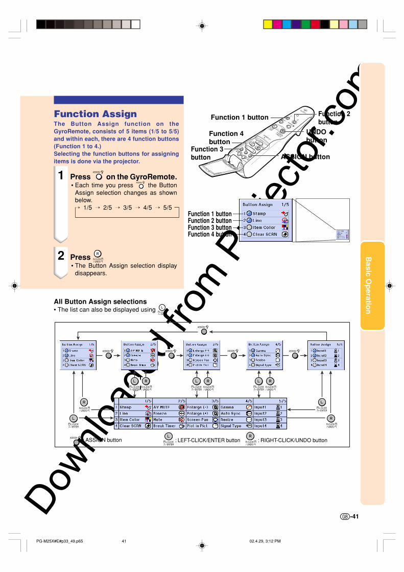
Function AssignThe Button Assign function on theGyroRemote, consists of 5 items (1/5 to 5/5)and within each, there are 4 function buttons(Function 1 to 4.)Selecting the function buttons for assigningitems is done via the projector.
1 Press on the GyroRemote.• Each time you press the Button
Assign selection changes as shownbelow. 1/5 2/5 3/5 4/5 5/5
2 Press • The Button Assign selection display
disappears.
Function 1 buttonFunction 2 buttonFunction 3 buttonFunction 4 button
Function 1 button Function 2button
Function 3button
Function 4button
ASSIGN button
UNDObutton
All Button Assign selections• The list can also be displayed using
GyroRemote ChannelSettingThe GyroRemote uses radio signals, whichcan receive interference under certainconditions. To avoid interference, when usingmultiple GyroRemotes, register a differentchannel for each GyroRemote in the projector.The GyroRemote has 8 channels for U.S.,Canada, etc. and 4 channels for Europe,Australia, Oceania and Aisa.
1 Press located on theGyroRemote.• You can also confirm the RF channel
by the number of times the LEDindicator flashes.(Ex: RF Channel 3 if the LED indicatorflashes 3 times.)
2 Hold for more than 1 sec.• Each time you press for over 1 sec.
the RF channel changes as shownbelow.For U.S., Canada, etc. 1 2 3 4 5 6 7 8
For Europe, Australia, Oceania and Asia 1 2 3 4
Registering the GyroRemotein the ProjectorWhen using one GyroRemote with multipleprojectors or one projector with multipleGyroRemotes, the GyroRemote(s) should bestored in the projector.
1 Select “Register R/C” in theOption (1) menu.
2 On the “Do you want to enter theLearn MOde?” (If the Gyro isconnected to projector by cable,temporarily unplug the cablefrom the projector and pressENTER button.) message,select “Yes” using or , andpress .
RF CH : 3
LEDindicator
RF CH+ button
Adjustment button("'\ |"'\ |"'\ |"'\ |"'\ |)
ENTER button
-42
PG-M25X#E#p33_49.p65 02.4.29, 3:12 PM42
Downlo
aded
from
Pro
jecto
r.com
Basic O
peratio
n
-43
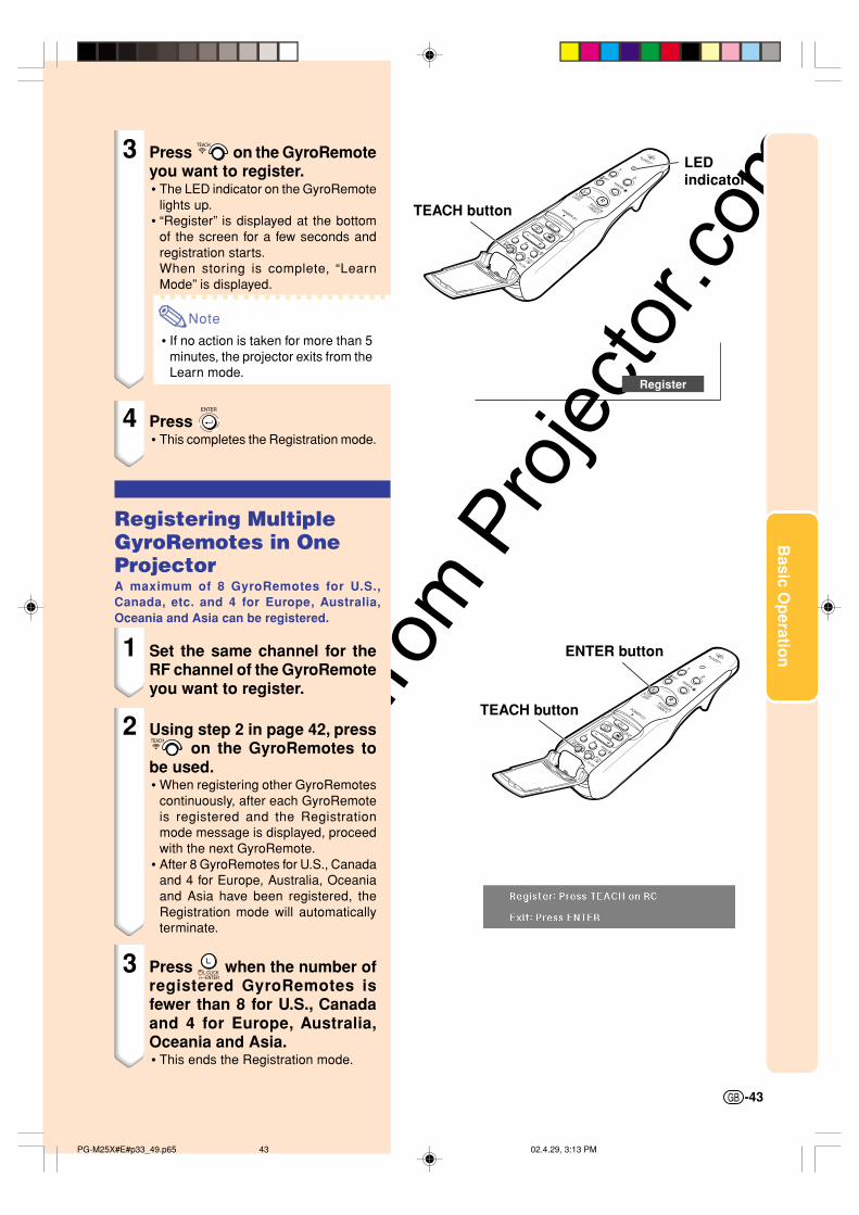
3 Press on the GyroRemoteyou want to register.• The LED indicator on the GyroRemote
lights up.• “Register” is displayed at the bottom
of the screen for a few seconds andregistration starts.When storing is complete, “LearnMode” is displayed.
Note
• If no action is taken for more than 5minutes, the projector exits from theLearn mode.
4 Press • This completes the Registration mode.
Registering MultipleGyroRemotes in OneProjectorA maximum of 8 GyroRemotes for U.S.,Canada, etc. and 4 for Europe, Australia,Oceania and Asia can be registered.
1 Set the same channel for theRF channel of the GyroRemoteyou want to register.
2 Using step 2 in page 42, press on the GyroRemotes to
be used.• When registering other GyroRemotes
continuously, after each GyroRemoteis registered and the Registrationmode message is displayed, proceedwith the next GyroRemote.
• After 8 GyroRemotes for U.S., Canadaand 4 for Europe, Australia, Oceaniaand Asia have been registered, theRegistration mode will automaticallyterminate.
3 Press when the number ofregistered GyroRemotes isfewer than 8 for U.S., Canadaand 4 for Europe, Australia,Oceania and Asia.• This ends the Registration mode.
TEACH button
LEDindicator
Register
TEACH button
ENTER button
PG-M25X#E#p33_49.p65 02.4.29, 3:13 PM43
Downlo
aded
from
Pro
jecto
r.com
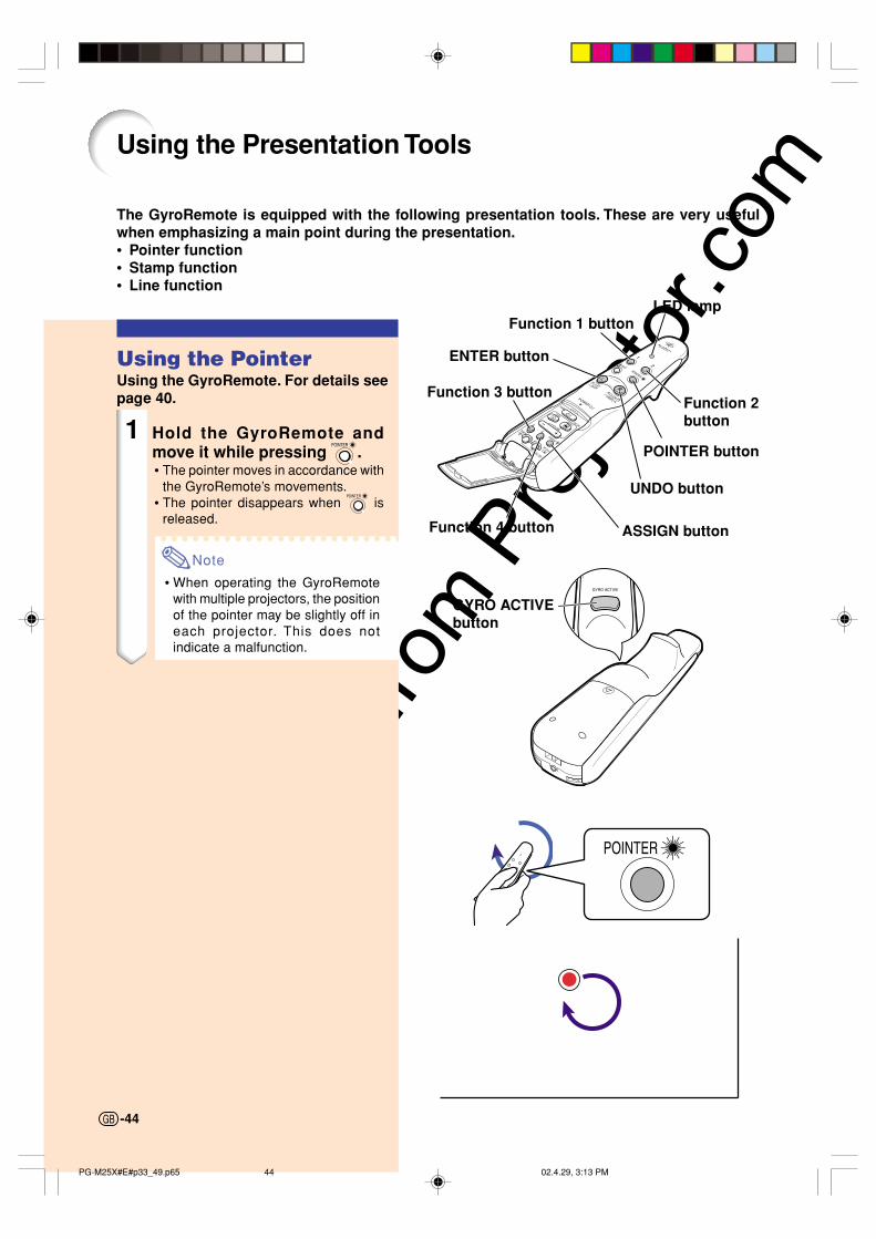
Using the Presentation Tools
The GyroRemote is equipped with the following presentation tools. These are very usefulwhen emphasizing a main point during the presentation.• Pointer function• Stamp function• Line function
Using the PointerUsing the GyroRemote. For details seepage 40.
1 Hold the GyroRemote andmove it while pressing .• The pointer moves in accordance with
the GyroRemote’s movements.• The pointer disappears when is
released.
Note
• When operating the GyroRemotewith multiple projectors, the positionof the pointer may be slightly off ineach projector. This does notindicate a malfunction.
Function 1 button
ENTER button
Function 3 button
Function 4 button
GYRO ACTIVEbutton
ASSIGN button
UNDO button
POINTER button
Function 2button
LED lamp
-44
PG-M25X#E#p33_49.p65 02.4.29, 3:13 PM44
Downlo
aded
from
Pro
jecto
r.com
Basic O
peratio
n
-45
Using the Stamp Func-tionUsing the GyroRemoteFor details see page 40.
1 Press on the GyroRemoteand then select “Button Assign1/5”.• The assign function is displayed at the
bottom right of the screen.
2 Press on the GyroRemote.• The stamp type will change every time
is pressed, as shown on the right.
3 Press on the GyroRemote toselect the color.• The stamp color will change every time
is pressed, as shown on the right.
4 Move the GyroRemote whileholding down .• The stamp will move on the screen.
5 Release at the locationon the screen that you want to
stamp, and press .• The stamp will be fixed at that location.
Note
• If you want to display another stamp, re-peat steps 2 to 4.
• Press to clear a stamp.• Even if the GyroRemote is moved,
will not function if it is not held down.
Red Green Blue Yellow
Black White Purple Light blue
PG-M25X#E#p33_49.p65 02.4.29, 3:13 PM45
Downlo
aded
from
Pro
jecto
r.comUsing the Line Function
Using the GyroRemote, you can draw on thescreen various shapes such as squares, ovals,horizontal, vertical, perpendicular and free-style lines.Using the GyroRemote,For details see page 40.
1 Press on the GyroRemote andthen select “Button Assign 1/5”.• The assign function is displayed at the
bottom right of the screen.
2 Press on the GyroRemote.• The type of drawing will change every time
is pressed, as shown on the right.
3 Press on the GyroRemote toselect the color.• The Line color will change every time
is pressed, as shown on the right.
4 Move the cursor to the startingposition while holding down
on the GyroRemote.
Note
• If you want to display another stamp,repeat steps 2 to 4.
• Press to delete a stamp justinserted.
• Press to clear all stamps.
5 Release on the Gyro-Remote and press .
6 Move the cursor to the endingposition while holding down
on the GyroRemote, andpress .
Note
• If you want to draw another shapeor line, repeat steps 1 to 5.
• Press to clear any shapes orlines you have just drawn in.
• Press to clear all shapes or linesyou have drawn in.
Diagonalline
Horizontalor vertical
line
Box Circle Free line
11
1
2
2
22
2
1
1: 2: :
How to drow lines and shapes
Red Green Blue Yellow
Black White Purple Light blue
Using the Presentation Tools (cont.)
Starting point Ending point Drawing direction
-46
PG-M25X#E#p33_49.p65 02.4.29, 3:13 PM46
Downlo
aded
from
Pro
jecto
r.com
Basic O
peratio
n
-47
Suppliedaccessory USB cable
USB port
Notebook computer
USB cable
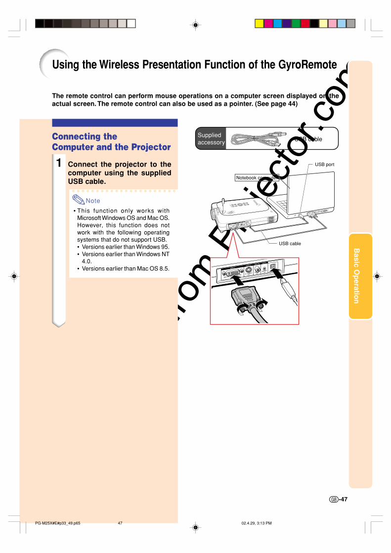
Using the Wireless Presentation Function of the GyroRemote
The remote control can perform mouse operations on a computer screen displayed on theactual screen. The remote control can also be used as a pointer. (See page 44)
Connecting theComputer and the Projector
1 Connect the projector to thecomputer using the suppliedUSB cable.
Note
• This function only works withMicrosoft Windows OS and Mac OS.However, this function does notwork with the following operatingsystems that do not support USB.• Versions earlier than Windows 95.• Versions earlier than Windows NT
4.0.• Versions earlier than Mac OS 8.5.
PG-M25X#E#p33_49.p65 02.4.29, 3:13 PM47
Downlo
aded
from
Pro
jecto
r.comUsing as a Wireless
Mouse
1 Move the GyroRemote whileholding down . The LEDindicator is lit.
2 Press or . It functionsthe same as the buttons of amouse connected to the com-puter.• In the case of one mouse button (such
as on a Macintosh) clicking this buttonwill function the same as either and .
Connecting theGyroRemote with aCableConnect the GyroRemote and projector usinga cable in places where signal reception isweak.
Note
• GyroRemote turns itself off if detachedfrom the ø25 to ø3.5 mm wired remotecontrol cable. To use it again, press to reactivate.
• When purchasing a ø2.5 to ø3.5 mm wiredremote cable, please contact Sharp Au-thorized Projector Dealer or Service Cen-ter.
Using the Wireless Presentation Function of the GyroRemote (Cont.)
L-CLICKbutton
LED indicator
R-CLICK button
GYRO ACTIVEbutton
-48
ø2.5 to ø3.5 remotecontrol cableavailable as Sharpservice part QCNW-5943CEZZ
ø3.5 minijack cable(commercially available oravailable as Sharp servicepart QCNW-4870CEZZ)
PG-M25X#E#p33_49.p65 02.4.29, 3:13 PM48
Downlo
aded
from
Pro
jecto
r.com
Basic O
peratio
n
-49
Turning Off theGyroRemoteMake sure to turn off the GyroRemote toprevent any unwanted operations, when notusing the projector. This also preventsconsumption of batteries set in theGyroRemote.
1 Press and located in-side the lower cover on theGyroRemote at the same timefor more than 2 seconds.• The LED Indicator will flash 3 times
and the GyroRemote will turn off.Any buttons pressed after (excluding
) will not emit signals.
2 Press on the GyroRemoteto turn on the GyroRemote.
Info
• Make sure to turn off theGyroRemote aboard aircraft orother places where using radiosignals is restricted.
Note
GyroRemote Sleep Function• In order to protect against battery
depletion, the GyroRemoteautomatically enters the Sleepmode when no operation takesplaces within more than 5 minutes.To cancel the Sleep mode refer tostep 2 above.
POWER button
RF CH+ button
TEACH button
PG-M25X#E#p33_49.p65 02.4.29, 3:13 PM49
Downlo
aded
from
Pro
jecto
r.comThis projector has three sets of menu screens that allow you to adjust the image and various
projector settings.You can operate the menus from the projector or GyroRemote using the following proce-dure.
Using the Menu Screen
On-screen menu for INPUT 1 RGB modeOn-screen menu for INPUT 2or INPUT 3 Mode
Menu Bar(Main Menu)
MENU button
"""""Menu Screen
Menu Selections on theProjector (Adjustments)
1 Press .• The menu screen is displayed.
Note
• The “Picture” menu screen isdisplayed in inputs 1, 2 and 3 andthe “Card” menu screen is displayedin INPUT 4 mode.
• The on-screen display shown on theright is displayed when the INPUT1 mode is selected.
On-screen menu for INPUT 4 RGB mode
ENTER button
-50
Menu Bar(Main Menu)
Menu Bar(Main Menu)
Adjustment buttons("'\ |"'\ |"'\ |"'\ |"'\ |)
PG-M25X#E#p50_64.p65 02.4.29, 3:14 PM50
Downlo
aded
from
Pro
jecto
r.com
Basic O
peratio
n
-51
2 Press or to select themenu you want to adjust.
Note
• For details on the menus, see thetree charts on pages 56 and 58.
• When using the GyroRemote tomove through a menu, see page 54.
3 Press or to selectthe item you want to adjust.
Note
• To display a single adjustment item,press after selecting the item.Only the menu bar and the selectedadjustment item will be displayed.Then if you press or ,the following item (“Phase” is after“Clock”) will be displayed.
• Press to return to the previous
screen.
4 Press or to adjust (set)the item selected.• The adjustment is stored.
5 Press .• The on-screen display is cleared.
|||||
PG-M25X#E#p50_64.p65 02.4.29, 3:15 PM51
Downlo
aded
from
Pro
jecto
r.com
Sub menu
MENU button
Adjustment buttons("'\ |"'\ |"'\ |"'\ |"'\ |)
ENTER button
Menu Screen
Menu Selections on theprojector (Settings)
1 Press .• The menu screen is displayed.
Note
• The “Picture” menu screen isdisplayed in inputs 1, 2 and 3 andthe “Card” menu screen is displayedin INPUT 4 mode.
• The on-screen display shown on theright is displayed when the INPUT 1mode is selected.
2 Press or to select themenu you want to adjust.
Note
• For details on the menus, see thetree charts on pages 56 and 58.
• When using the GyroRemote tomove through a menu, see page 55.
3 Press or to selectthe item you want to set.
Note
• Press to return to the previousscreen.
• In some menus, select the icon us-ing “ ”.
Using the Menu Screen (cont.)
-52
PG-M25X#E#p50_64.p65 02.4.29, 3:15 PM52
Downlo
aded
from
Pro
jecto
r.com
Basic O
peratio
n
-53
4 Press .• The cursor shifts to the sub menu.
5 Press or to selectthe setting of the itemdisplayed in the sub menu.
6 Press .• The item selected is set.
Note
• Some adjustment items will displaya confirmation message.
When setting an item, press or
to select “Yes” or “OK” and then
press .
7 Press .• The menu will disappear and the
adjustment is stored.
Sub menu
PG-M25X#E#p50_64.p65 02.4.29, 3:15 PM53
Downlo
aded
from
Pro
jecto
r.com
1
2
3
On-screen menu for INPUT 1 mode
MENU button
GYRO ACTIVEbutton
GYRO ACTIVEbutton
(Rear)
Menu Bar(Main Menu)
-54
Using the Menu Screen (cont.)
Using the GyroRemote toNavigate the On-screenMenu (Adjustments)
1 Press .• The menu screen is displayed.
Note
• The “Picture” menu screen isdisplayed in inputs 1, 2 and 3 andthe “Memory Card” menu screen isdisplayed in INPUT 4 mode.
• The screen on the right shows theINPUT 1 mode screen.
2 11111While holding down ,move the GyroRemote leftand right to select the menu.
Note
• The GyroRemote will not function if
is not held down.
• If is pressed twice, the function will remain active without
having to hold down .(The LED indicator will remain lit.)
If is pressed again, the function will be released and theLED indicator will turn off.
• If is pressed on the menubar, the menu can be selected.
22222While holding down ,move the GyroRemote up ordown to select an item.
33333While holding down ,move the GyroRemote to theright and the left to adjust(set) the selected item.
Note
• The adjustment is stored.• Pressing can also adjust.
3 Press .• The menu display disappears.
PG-M25X#E#p50_64.p65 02.4.29, 3:15 PM54
Downlo
aded
from
Pro
jecto
r.com
Basic O
peratio
n
MENU button
GYRO ACTIVEbutton
Using the GyroRemoteto Navigate the On-screen Menu (Settings)
1 Press .• The menu screen is displayed.
Note
• The “Picture” menu screen isdisplayed in inputs 1, 2 and 3 andthe “Memory Card” menu screen isdisplayed in INPUT 4 mode.
• The screen on the right shows theINPUT 1 mode screen.
2 11111While holding down ,move the GyroRemote leftand right to select the menu.
Note
• The GyroRemote will not function if
is not held down.
• If is pressed twice, the function will remain active without
having to hold down .(The LED indicator will remain lit.)
If is pressed again, the function will be released and theLED indicator will turn off.
• If is pressed on the menubar, the menu can be selected.
22222While holding down ,move the GyroRemote up ordown to select an item.
33333While holding down ,move the GyroRemote to theright.
• The cursor will move to the submenu.
44444While holding down ,move the GyroRemote up ordown to select items on thesub menu.
This list shows the items that can be set in the projector.
INPUT 1 Mode
Page 106
Note
• The resolution, vertical frequency and horizontal frequency figures displayed above are for examplepurposes only.
• When DVI digital signals have been entered into INPUT 1, in “Picture” only “CLR Temp”, “Red” and “Blue”can be adjusted and in “Fine Sync” only “Signal Info”, “Auto Sync” and “Auto Sync Disp” can be used.
• When the signal type is set as “Component”, in the “Picture” menu of INPUT 1 “Color”, “Tint” and “Sharp”are displayed.
• Some items cannot be reset, even when “All Reset” in Options (2) has been selected. For details see page 105.
• Some items will not be reset, if you select All Reset in Options (2). For details, see page 105.
PG-M25X#E#p50_64.p65 02.4.29, 3:15 PM58
Downlo
aded
from
Pro
jecto
r.com
Basic O
peratio
n
Adjusting the PictureYou can adjust the projector’s picture to your preferences with the following picture settings.
Selected Item Description button button
Contrast
Bright
Color
Tint
Sharp
Red
Blue
CLR Temp
For adjusting the contrast level
For adjusting the brightness of an image
For adjusting the color intensity of the image
For adjusting the tones of an image
For making sharper or softer the contour of an image
For adjusting the redness level
For adjusting the blue level
For adjusting the color temperature of an image
For less contrast
For less brightness
For less color intensity
Skin tones become purplish
For less sharpness
For weaker red
For weaker blueDecreases colortemperature for warmer,reddish, incandescent-like images.
For more contrast
For more brightness
For more color intensity
Skin tones become greenish
For more sharpness
For stronger red
For stronger blueIncreases colortemperature for cooler,bluish, fluorescent-likeimages.
Adjusting ImagePreferencesAdjust the Picture menu on the menuscreen. For operating the menu screen, seepages 50 and 52. For operating the menu screen usingthe GyroRemote see pages 54 and 55.
Note• “Color”, “Tint” and “Sharp” are not dis-
played when selecting INPUT 1 and the“Signal Type” is “RGB” .
• The picture adjustments can be storedseparately in each input mode.
• When the signal type in INPUT 1 hasbeen set to Component, “Sharp” can beadjusted when 480I, 480P, 720P or 1080Isignals are entered.
• To reset all adjustment items, select “Re-set” and press .
Selecting the Signal TypeThis function allows you to select the inputsignal type RGB or Component for INPUT1.
Select “Signal Type” in the “Picture”menu on the menu screen. For operating the menu screen, seepages 50 and 52. For operating the menu screen usingthe GyroRemote see pages 54 and 55.
Note
• RGBSet when RGB signals are received.
• ComponentSet when Component signals are received.
-59
PG-M25X#E#p50_64.p65 02.4.29, 3:16 PM59
Downlo
aded
from
Pro
jecto
r.comProgressive Mode
This function allows you to select the pro-gressive display of a video signal. The pro-gressive display projects a smoother videoimage.
Select “Progressive Mode” in the “Pic-ture” menu on the menu screen. For operating the menu screen, seepages 50 and 52. For operating the menu screen usingthe GyroRemote see pages 54 and 55.
Note
• 2D ProgressiveThis function is useful to display fast-movingimages such as sports and action films. Thismode optimizes the image in a displayed frame.
• 3D ProgressiveThis function is useful to display relativelyslow-moving images such as drama anddocumentary more clearly.This mode optimizes the image by estimat-ing the movement of a number of preced-ing and succeeding frames.
• Film ModeReproduces the image of film source clearly.Displays the optimized image of filmtransformed with three-two pull down (NTSCand PAL60Hz) or two-two pull down(PAL50Hz and SECAM) enhancement toprogressive mode images.* The film source is a digital video recording
with the original encoded as is at 24 frames/second. The projector can convert this filmsource to progressive video at 60 frames/second with NTSC and PAL60Hz or at 50frames/second with PAL50Hz and SECAMto play back a high-definition image.
• When using progressive inputs, these inputsare directly displayed therefore 2DProgressive, 3D Progressive and Film Modecannot be selected. These modes can beselected in interlace signals other than 1080I.
• In NTSC or PAL60Hz, even if the 3D Progres-sive mode has been set, the three-two pulldown enhancement will be enabled automati-cally, when the film source has been entered.
• In PAL50Hz or SECAM, the two-two pulldown enhancement will be enabled only inthe Film Mode, when the film source hasbeen entered.
-60
Adjusting the Picture (cont.)
PG-M25X#E#p50_64.p65 02.4.29, 3:16 PM60
Downlo
aded
from
Pro
jecto
r.com
Basic O
peratio
n
Adjusting Computer Images
Use the Fine Sync function in case of irregularities such as vertical stripes or flickering inportions of the screen.
When Auto Sync is OFFWhen “Auto Sync” is “OFF”, interferencesuch as flickering or vertical stripes may oc-cur if displaying tilings or vertical stripes.Should this occur, adjust “Clock”, “Phase”,“H-Pos” and “V-Pos” for obtaining an opti-mum image.
Select “Clock”, “Phase”, “H-Pos” or “V-Pos” in the “Fine Sync” menu on themenu screen. For operating the menu screen, seepages 50 and 52. For operating the menu screen usingthe GyroRemote see pages 54 and 55.
Note
• Computer image adjustments can be madeeasily by pressing . See page 63 fordetails.
Saving AdjustmentSettingsThis projector allows you to store up to sevenadjustment settings for use with various com-puters.
Select “Save Setting” in the “Fine Sync”menu on the menu screen. For operating the menu screen, seepages 50 and 52. For operating the menu screen usingthe GyroRemote see pages 54 and 55.
Selected Item Description
Clock
Phase
H-Pos
V-Pos
Adjusts vertical noise.
Adjusts horizontal noise (similar to tracking on your VCR).
Centers the on-screen image by moving it to the left or right.
Centers the on-screen image by moving it up or down.
-61
PG-M25X#E#p50_64.p65 02.4.29, 3:16 PM61
Downlo
aded
from
Pro
jecto
r.com
-62
Selecting Adjustment SettingsAdjustment settings stored in the projectorcan be easily accessed.
Select “Select Setting” in the “FineSync” menu on the menu screen. For operating the menu screen, seepages 50 and 52. For operating the menu screen usingthe GyroRemote see pages 54 and 55.
Note
• If a memory position has not been set, aresolution and frequency setting will notbe displayed.
• When selecting a stored adjustment set-ting with “Select Setting”, you can set theprojector in the stored adjustments.
Special Mode SettingsOrdinarily, the type of input signal is detectedand the correct resolution mode is automati-cally selected. However, for some signals, theoptimal resolution mode in “Special Modes” onthe “Fine Sync” menu screen may need to beselected to match the computer display mode.
Set the resolution by selecting “SpecialModes” in the “Fine Sync” menu on themenu screen. For operating the menu screen, seepages 50 and 52. For operating the menu screen usingthe GyroRemote see pages 54 and 55.
Note
• Avoid displaying computer patterns whichrepeat every other line (horizontal stripes).(Flickering may occur, making the imagehard to see.)
• When a DVD player or Digital Video isconnected, select 480P as the input sig-nal.
• See “Checking the Input Signal” below forinformation on the currently selected inputsignal.
Adjusting Computer Images (cont.)
-62
PG-M25X#E#p50_64.p65 02.4.29, 3:16 PM62
Downlo
aded
from
Pro
jecto
r.com
Basic O
peratio
n
Checking the Input SignalThis function allows you to check the currentinput signal information.
Select “Signal Info” in the “Fine Sync”menu on the menu screen. For operating the menu screen, seepages 50 and 52. For operating the menu screen usingthe GyroRemote see pages 54 and 55.
Note
• The projector will display the number ofscanned lines available input from audio-visual equipment such as a DVD playeror Digital Video.
Auto Sync AdjustmentUsed to automatically adjust a computer image.
Select “Auto Sync” in the “Fine Sync”menu on the menu screen. For operating the menu screen, seepages 50 and 52. For operating the menu screen usingthe GyroRemote see pages 54 and 55.
Note
When setting to “ Normal” or“ High Speed”:• Auto Sync adjustment will occur when the
projector is turned on or when the inputsare switched, when connected to a com-puter.
Manual adjustments should be per-formed:• When the optimum image cannot be
achieved with Auto Sync adjustment. Seepage 61.
• Auto Sync adjustment may take sometime to complete, depending on the im-age of the computer connected to theprojector.
• When making adjustments using theAUTO SYNC button on the projector.
• When setting “Auto Sync” to “OFF” or“High Speed”, and if is pressed AutoSync will be executed in “High Speed”mode. If the button is pressed againwithin one minute, Auto Sync will be ex-ecuted in “Normal” mode.
• Adjustments can also be made byselecting “Auto Sync” using the Button As-sign function.
Screen display during Auto Sync
-63
PG-M25X#E#p50_64.p65 02.4.29, 3:16 PM63
Downlo
aded
from
Pro
jecto
r.com
-64
Auto Sync DisplayFunctionUsed to set the screen displayed during AutoSync.
Select “Auto Sync” in the “Fine Sync”menu on the menu screen. For operating the menu screen, seepages 50 and 52. For operating the menu screen usingthe GyroRemote see pages 54 and 55.
Note
• .....The image set as a backgroundimage is projected.
• ..... The computer image being ad-justed is displayed.
-64
Adjusting Computer Images (cont.)
PG-M25X#E#p50_64.p65 02.4.29, 3:16 PM64
Downlo
aded
from
Pro
jecto
r.com
Easy to
Use F
un
ction
s
Easy to Use Functions
PG-M25X#E#p65_77.p65 02.4.29, 3:18 PM65
Downlo
aded
from
Pro
jecto
r.com
-66
Before setting the networkThis section explains items that can be set in a network. A wireless connection will not be possible if theseitems are not set correctly.Also, as there are values that must be entered in a pre-configured network, make sure to consult with yournetwork administrator.
IP Address When What is an IP Address?
The IP Address is a number for identifying devices connected to the network. An IP address must beassigned to each device using network values.
Connecting the projector and a computer via a wireless connection is the same as the computer andprojector being connected to a wireless LAN network. Therefore, if the projector (and computer) is notassigned an IP address, they cannot be identified and thus a wireless connection cannot be possible.
192.168.150.150
192.168.150.153
192.168.150.154
192.168.150.151
192.168.150.152
Assigning IP addressesWhen creating a local network where the projector and a computer are connected in a wireless environment,192.168.0.1 to 192.168.255.254 can be assigned as the IP addresses for the devices connected to thatnetwork.The IP address of the projector is 192.168.0.1 and as long as there are no conflicts, the default settings donot have to be changed.
This projector comes with a DHCP server function that automatically assigns IP addresses to devicesconnected to the network.For details, see page 70.
Note
• The range of IP addresses that can be assigned in a local network is fixed.• IP stands for Internet Protocol.
Using the Network
PG-M25X#E#p65_77.p65 02.4.29, 3:18 PM66
Downlo
aded
from
Pro
jecto
r.com
Easy to
Use F
un
ction
s
-67
Wireless Channels What is a wireless channel?
A wireless channel is a frequency used by wireless LAN cards when communicating. 14 channels can beused. If other wireless LAN networks are being used near the location where the projector is, make surethat different channels have been set to avoid interference.
Assigned wireless channelsIf there are no other networks that can cause interference nearby, set either 1, 6, 13, or 14.The wireless channel set in the projector is 192.168.0.1 and as long as there are no conflicts, the defaultsettings do not have to be changed.
For settings, see page 71.
DHCP server function
What is a DHCP function?The DHCP server function automatically assigns IP addresses to devices connected to the network. Whenthe Network Settings on the computer have been set to Automatically get IP address (DHCP server enabled),the projector will automatically assign IP addresses.
11ch
6ch
1ch
Make the following settings when using this functionSet the DHCP server function on the projector to ON.Set the start value of the IP address assigned and an expected number of IP address to be automaticallyassigned (Maximum number to be assigned).
For settings, see page 73.
Note
• DHCP stands for Dynamic Host Configuration Protocol.
192.168.150.154192.168.150.151
192.168.150.152 192.168.150.153
PG-M25X#E#p65_77.p65 02.4.29, 3:18 PM67
Downlo
aded
from
Pro
jecto
r.com
68
Using a Wireless LAN PC Card
Inserting a wireless LAN PC card into the INPUT 4 slot on the projector allows you to sendimages to the projector and project them via a wireless connection.
-68
Installing a WirelessLAN PC Card
1 Insert the wireless LAN PCcard into the INPUT 4 slot onthe projector.• For details on how to install the card,
see page 31.• When the card is inserted, the input
will automatically change to INPUT 4.
Note
• See page 75 when installing a memorycard in the projector.
• Installation should be done after “Stand-by” is displayed.
Ejecting the CardMake sure to perform the following pro-cedures before removing the card. Se-lect “Eject PC Card” in the Card menuon the menu screen. For operating the menu screen, seepages 50 and 52. For operating the menu screen usingthe GyroRemote see pages 54 and 55.
1 Select “Eject PC Card” and
press .• After a few seconds, the message “You
may safely eject the PC Card” will bedisplayed.
2 Remove the card.• Remove the card after the message
is displayed.
Info
• When moving the projector, make surethat the Eject button is pressed all theway in. If moved with the Eject button out,the projector may be damaged.
PG-M25X#E#p65_77.p65 02.4.29, 3:18 PM68
Downlo
aded
from
Pro
jecto
r.com
Easy to
Use F
un
ction
s
-69
Network Settings
Note
• This section explains items that can be set in a network. A wireless connection will not be possible if theseitems are not set correctly.
• Also, as there are values that must be entered in a pre-configured network, make sure to consult with yournetwork administrator.
Setting Up a Projector NameThis Network setting assigns a name to the pro-jector. The default setting is “MY PROJECTOR”.When selecting “Projector” in the net-work menu on the menu screen For operating the menu screen, seepages 50 and 52. For operating the menu screen usingthe GyroRemote see pages 54 and 55.
1 Press or to select“Projector” and then press .
2 Press in “Name”.
3 Press or to selectthe characters you want to set.
• Pressing or switchesbetween procedures as shown below.
• If you want to delete one charactor to theleft, select “BS” by pressing or
and press .• The projector name is displayed when the
projector has been found via the computer.
4 Press .
Note• If you want to correct a letter or symbol,
press or to move the cursor to the
character you want to correct, and then use or to correct the character.
• Characters can also be selected using on the GyroRemote.
• If you want to cancel the settings, press .
PG-M25X#E#p65_77.p65 02.4.29, 3:18 PM69
Downlo
aded
from
Pro
jecto
r.com
70
Network Settings (cont.)
-70
5 Repeat steps 3 and 4 to enter theremaining characters you want.
Note
• A maximum of 16 characters can beentered
6 Press .• The settings are stored and active.
Setting the IP AddressSet the IP Address of the projector.Set “TCP/IP” in the network menu on themenu screen. For operating the menu screen, seepages 50 and 52. For operating the menu screen usingthe GyroRemote see pages 54 and 55.
1 Press or to selectTCP/IP and then press .
2 Press or to select“IP Address”, and then press
.
3 Press or to selectthe values you want to set.
4 Press or to move thecursor to the digit you want tocorrect.
Note
• You can also move the cursor by pressing on the GyroRemote.
• If you want to cancel the settings, press
.
PG-M25X#E#p65_77.p65 02.4.29, 3:18 PM70
Downlo
aded
from
Pro
jecto
r.com
Easy to
Use F
un
ction
s
-71
5 Repeat steps 3 and 4 to set allthe digits.
Setting the GatewaySelect “Gateway” using the procedure instep 1, and enter the values by repeatingthe procedure in step 3 and 4.
Setting the Subnet MaskSelect “Subnet Mask” using the procedurein step 1, and enter the values by repeatingthe procedure in step 3 and 4.
6 Press
Setting the Wireless ChannelSet the wireless LAN channel so that nointerference occurs with another wirelesschannel.Select “Wireless LAN” in the networkmenu on the menu screen. For operating the menu screen, seepages 50 and 52. For operating the menu screen theGyroRemote see pages 54 and 55.
1 Press or to select“Wireless LAN” and the press
.
2 Press or to select
“Channel” and then press .
3 Press or to selectthe wireless channel numberyou want to set.
Note
• Depending on the country andgeographical location, wireless channelsthat can be used are limited. Read theWireless LAN PC Card Cautions about thewireless channels that can be used.
• The channels that can be used are fromchannel 1 to 11 depending on the countly.
4 Press .
PG-M25X#E#p65_77.p65 02.4.29, 3:19 PM71
Downlo
aded
from
Pro
jecto
r.com
72
Network Settings (cont.)
-72
Setting the SSIDSet the projector’s SSID.The default setting is “SHARP_PRJ”.Select “Wireless LAN” in the networkmenu on the menu screen For operating the menu screen, seepages 50 and 52. For operating the menu screen usingthe GyroRemote see pages 54 and 55.
1 Press or to select
“Wireless LAN” and then press .
2 Press or to select
“SS ID” and then press .
3 Press or to selectthe characters you want to set.
Note
• The characters can be entered fllowing:Letters (A to Z), numerical (0 to 9),symbols (–, _, ( ))
• If you want to delete one character to theleft, select “BS” and press .
4 Press .• You can also move the cursor using
on the GyroRemote.
Note
• If you want to correct a letter or symbol,
press or to move the cursor to the
character you want to correct, and then use or to correct the character.
• If you want to cancel the settings, press .
5 Repeat steps 2 and 3 to set allthe characters.
Note
• A maximum of 16 characters can be set.
6 Press .• The settings are enabled.
PG-M25X#E#p65_77.p65 02.4.29, 3:19 PM72
Downlo
aded
from
Pro
jecto
r.com
Easy to
Use F
un
ction
s
-73
Setting the DHCPServerThis function is set when using the DHCPserver on the projector.Set “DHCP Server” in the network menuon the menu screen. For operating the menu screen, seepages 50 and 52. For operating the menu screen usingthe GyroRemote see pages 54 and 55.
Enabling the DHCP server functionSet the “Server” in the submenu to “ON”.Set the “Server” to “OFF” when not usingthe DHCP server function.
Note
• When the DHCP server function of theprojector has been set in a wireless LANwhere there is another DHCP serverconnected, the network may not functioncorrectly. If there is another DHCP serverconnected, make sure to consult with yourNetwork Administrator.
Setting the Assign “Start Address”Set the Assign Start Address in StartAddress in the Submenu.
For setting the start address, see theprocedure in Setting the IP Address.
Assigning a maximum number of IPaddresses
This function is for setting the maximumnumber of IP addresses from the startaddress that can be automatically assigned.
Make sure to set an approximateamount of the computers that are tobe connected to the wireless LAN.You can set anywhere between 1 to250 computers.
Note
• Assign “Start Address” and “Max Lease”can be set when the DHCP server functionis OFF.
• IP addresses will not be sorted if theirnumber is more than 250.
Select “Yes”
PG-M25X#E#p65_77.p65 02.4.29, 3:19 PM73
Downlo
aded
from
Pro
jecto
r.com
-74
Resetting the NetworkSettingsThis will return the default values of theNetwork Settings.Select “Reset” in the Network menu onthe menu screen. For operating the menu screen, seepages 50 and 52. For operating the menu screen usingthe GyroRemote see pages 54 and 55.
Network Settings (cont.)
Wireless LAN PC card: Troubleshooting
Check the following if you cannot connect to the network using your wireless LAN PC card.1. Is the Link indicator o the wireless LAN PC card light?
• Lit: operating normally.• Flashing: the wireless LAN PC card driver is not operating properly.
Reinstall the driver in the computer.• Off: The card is not in operation. Make sure that the card is installed correctly.
2. Are the SSID, channel and wireless transmission settings of the projector and computer the same?• If the SSID, channel and wireless transmission settings of the computer are not the same, then they
cannot communicate.• When communicating with the projector, make sure that the transmission mode has been set to 802.11
ad hoc mode.
3. Check the projector and computer network settings.
When the DHCP “Server” on the projector is “OFF”:Check again the IP address, subnet mask and gateway values of the projector and computer.
When the DHCP server on the projector is ON:Check the values of the IP address, subnet mask and DHCP assigned start address of the projector.
If part of the IP address or DHCP assign start address is not identical to the ones specified in thesubnet mask, IP address assigning cannot be properly done.
If the above procedure is carried out and the wireless LAN PC card still does not operate, see the WirelessReality software operation manual.
192.168.150.120
255.255.255.0
192.168.150.100...correct
192.168.050.100...wrong
IP address
Subnet mask
Assign start address
Assign start address
PG-M25X#E#p65_77.p65 02.4.29, 3:19 PM74
Downlo
aded
from
Pro
jecto
r.com
Easy to
Use F
un
ction
s
Using a Memory Card
When a memory card is installed, images stored in the memory card can be projected.If presentation files are stored in the memory card you can make presentations using onlythe projector and the memory card, without having to use a computer.
-75
Displaying of theContents in the Card asan Index
1 Insert the memory card into theINPUT 4 terminal on the projector.• For details on installing the card, see
page 31.• The current mode will automatically
change to INPUT 4 mode, when thePC Card is inserted into INPUT 4terminal, and the files stored in thecard will be displayed as an index.(Index mode)
Note
• For details about the display format of theIndex mode, see pages 76,77.
• For details on how to install the wirelessLAN card in the projector, see page 68.
• The following are the files that thisprojector can handle.
Ejecting the CardMake sure to perform the following proceduresbefore removing the card.Select Card eject in the Card menu onthe menu screen For operating the menu screen, seepages 50 and 52. For operating the menu screen usingthe GyroRemote see pages 54 and 55.
1 Select “Eject PC Card” andpress .• After a few seconds, the message “You
may safely eject the PC Card” will bedisplayed.
PG-M25X#E#p65_77.p65 02.4.29, 3:19 PM75
Downlo
aded
from
Pro
jecto
r.com
-76
2 Remove the card.• Remove the card after the message
is displayed.• For details on how to remove the card,
see page 31.
Info
• When moving the projector, make sure thatthe Eject button is pressed all the way in. Ifmoved with the Eject button out, the projec-tor may be damaged.
Setting the ThumbnailDisplayYou can display JPEG files and slide show VQfiles as thumbnails. Some files may not bedisplayed as thumbnails.Images files that cannot be displayed asthumbnails or other files except images willbe displayed only as file names.
• Other file names except for folders, imagefiles, and script files will be displayed in gray.
• The folders are displayed in [ ].• The file names will be displayed in 8
characters with their extensions (3characters).
Moving folders• Press or to
select the folder and press .
• To move the folder up one level,select and press .
Projecting a file• Press or to
select the folder and press .• The selected image is displayed.• If you press while the image is
displayed, the submenu is displayed.• “Next” ...............Proceeds to the next page.• “Previous” ........Moves back one page.• “Rotate (right)” ...Turns the image to the
right by 90°.• “Rotate (left)” ...Turns the image to the
left by 90°.• “Index” ..............Quits automatic display
of images.The screenreturns to Index mode.
Changing the page displayed• Select or and press .
Using a Memory Card (cont.)
-76
PG-M25X#E#p65_77.p65 02.4.29, 3:19 PM76
Downlo
aded
from
Pro
jecto
r.com
Easy to
Use F
un
ction
s
-77
Setting ListsYou can display files in lists.For list settings, see page 78.
Moving files
• Press or to
select the folder and press .
• To move the folder up one level,
select and press .
Projecting a file
• Press or or to
select the folder and press .• The selected image is displayed.
Changing the page displayed
• Select or and press .
PG-M25X#E#p65_77.p65 02.4.29, 3:19 PM77
Downlo
aded
from
Pro
jecto
r.com
-78
Memory Card Settings
Setting FilesYou can limit the files displayed in the Indexmode according to their type.Select “Display File” in the MemoryCard menu on the menu screen. For operating the menu screen, seepages 50 and 52. For operating the menu screen usingthe GyroRemote see pages 54 and 55.
Note
• All FilesAll the files and folders are displayed.
• Image FileOnly images fi les and folders aredisplayed. The types of images files thatcan be displayed are as follows:JPEG, VQ, TIFF, BMP.
• Script File (.SSF)Only slide show script files and folders aredisplayed.
Setting the DisplayOrder of FilesYou can set the display order of files displayedin the Index mode.Select “Sort” in the Memory Card menuon the menu screen. For operating the menu screen, seepages 50 and 52. For operating the menu screen usingthe GyroRemote see pages 54 and 55.
Note
Files can be displayed in:• Name or alphabetical order.• New date order• Old date order• File type order
-78
PG-M25X#E#p78_96.p65 02.4.29, 3:20 PM78
Downlo
aded
from
Pro
jecto
r.com
Easy to
Use F
un
ction
s
Setting the DisplayFormat of the Index ModeSelect “View” in the Memory Card menuon the menu screen. For operating the menu screen, seepages 50 and 52. For operating the menu screen usingthe GyroRemote see pages 54 and 55.
Note
• Thumbnail displayFor displaying the contents of the memorycard as thumbnails.
• List displayFor displaying the contents of the memorycard in a list.
Using AutorunThe Autorun function works under thefollowing cases:
• When the projector is turned on with thecard installed.
• When install ing the card while theprojector is on.
Select “Autorun” in the Memory Cardmenu on the menu screen. For operating the menu screen, seepages 50 and 52. For operating the menu screen usingthe GyroRemote see pages 54 and 55..
“OFF”For disabling the Autorun function.
“Script File”When the script files which are createdby Slide Manager of the Wireless Realityare stored in the memory card, the Auto-Run will automatically load the script filesand then projects the image files in orderaccording to the script files.
• The display interval between images isregulated in the script file.
• The script file can be made using the slidemanager included with your projector.
“Slide Show”The image files stored in the rootdirectory in the memory card will beprojected in order automatically.
-79
PG-M25X#E#p78_96.p65 02.4.29, 3:21 PM79
Downlo
aded
from
Pro
jecto
r.com
80
Memory Card Settings (cont.)
-80
Setting the DisplayInterval for Image FilesYou can set the display interval for slide showfiles (image files).
Adjust “Interval” in the Memory Cardmenu on the menu screen. For operating the menu screen, seepages 50 and 52. For operating the menu screen usingthe GyroRemote see pages 54 and 55.
Pressing the button during imageprotection via the Autorun function willdisplay the submenu.
• “Next” ............... Proceeds to the nextpage.
• “Previous” ........ Moves back one page.• “Index Mode” ... Quits automatic display
of images. The screenreturns to Index mode.
Info
• Pressing any button on the projector oron the GyroRemote during Autorun, theAutorun function stops.
Note
• During Slide Show playback, the OSDmessage “Please wait” wil l appearbetween slides. This message can beeliminated by selecting “ Level A” or“ Level B” in “OSD Display” See page89 to disable OSD messages.
PG-M25X#E#p78_96.p65 02.4.29, 3:21 PM80
Downlo
aded
from
Pro
jecto
r.com
Easy to
Use F
un
ction
s
-81
Displaying a Still Image
This function allows you to instantly freeze a moving image. This is useful when you want todisplay a still image from a computer or video, giving you more time to explain the image tothe audience.
Function 2button
"On-screen Display
ASSIGN button
Storing an Image inStill Image FormatFor using the GyroRemote, see page 40for details.
1 Press to display “ButtonAssign 2/5”.• The Assign function is displayed at the
bottom right of the screen.
2 Press .• The image currently being projected
becomes a still image.
3 Press again to return to themoving image from the cur-rently connected device.
Info
• Still picture functions 4 do not work in thein INPUT 4.
PG-M25X#E#p78_96.p65 02.4.29, 3:21 PM81
Downlo
aded
from
Pro
jecto
r.com
-82
Selecting the Picture Display Mode
This function allows you to modify or customize the picture display mode to enhance theinput image. Depending on the input signal, you can choose “NORMAL”, “FULL”, “DOT BYDOT”, “BORDER”, “STRETCH” or “SMART STRETCH” image.
ASSIGNbutton
Screen display of the picture display mode
Function 3button
Switching the PictureDisplay Using DifferentInput SignalsFor using the GyroRemote, see page 40for details.
1 Press to display “ButtonAssign 4/5”.• The Assign function is displayed at the
bottom right of the screen.
2 Press .
Info
• In the “DOT BY DOT” mode, images arediplayed with the original resolution,therefore they are not enlarged.
• To return to the previous mode, press whle “RESIZE” is displayed on the screen.
-82
PG-M25X#E#p78_96.p65 02.4.29, 3:21 PM82
Downlo
aded
from
Pro
jecto
r.com
Easy to
Use F
un
ction
s
-83
4:3 aspect ratio
Other aspect ratios
SVGA (800 × 600)
XGA (1024 × 768)
SXGA (1280 × 960)
UXGA (1600 × 1200)
SXGA (1280 × 1024)
NORMAL
1024 × 768
1024 × 768
1024 × 768
1024 × 768
960 × 768
FULL
—
—
—
—
1024 × 768
DOT BY DOT
800 × 600
—
1280 × 960
1600 × 1200
1280 × 1024
480I, 480P, NTSC
PAL, SECAM
720P, 1080I
4:3 aspect ratio.
Letter box, squeeze
16:9 aspect ratio
NORMAL
1024 × 768
—
BORDER
768 × 576*
—
STRETCH
1024 × 576*
SMART STRETCH
1024 × 576*
—
Resolution lower than
XGA
NORMALProjects a full screen image
while maintaining the aspect ratio.
FULLProjects a full screen image
while ignoring the aspect ratio.
DOT BY DOTProjects the original resolution
signal of the image.
4:3 aspect ratio
Input Signal
Output screen image
XGA
Resolution higher than
XGA
480I, 480P, NTSC,
PAL, SECAM
4:3 aspect ratio
Input Signal
Output screen image
720P, 1080I
Letter box
Squeeze
16:9 aspect ratio
COMPUTER
VIDEO
• When XGA (1024 x 768) signals have been entered or when using INPUT 4 Mode, they will be fixed as NORMAL.
• “STRETCH” is fixed when 720P or 1080I signals are entered.* The Digital Shift function can be used with these images.
4:3 aspect ratio
4:3 aspect ratio
SXGA (1280 × 1024)
SMART STRETCHProjects the image fully in a
16:9 screen by enlarging onlythe surrounding areas whilekeeping the aspect ratio in
the middle part of the imageat 4:3.
NORMAL
Projects a full screen image.
BORDER
Projects 4:3 image fully inSTRETCH (the following
column) image.
STRETCH
Projects 16:9 image evenlyover entire screen
(top/bottom black bands).
PG-M25X#E#p78_96.p65 02.4.29, 3:21 PM83
Downlo
aded
from
Pro
jecto
r.com
-84
This function allows you to enlarge a specific portion of an image. This is useful when youwant to display a detailed portion of the image.
UNDObutton
Function 2button
ASSIGNbutton
Function 1button
-84
"On-screen Display
Screen movingindicator
Displaying an EnlargedPortion of an ImageFor using the GyroRemote, see page 40for details.
1 Press to display “ButtonAssign 3/5”.• The Assign function is displayed at the
bottom right of the screen.
2 Press Function Button toenlarge the image.• To reduce the size of the enlarged
image, press Function Button .
Note
×1 ×4 ×9 ×16 ×36 ×64×2 ×3
To enlarge
To reduce
• When an SXGA+ or UXGA image isdisplayed, “×2” and “×3” cannot beselected.
3 Hold down and move the
GyroRemote to move theenlarged image.• If the Screen moving mark has
disappeared, press Function Button
to display the Screen move mark,
and then move the image.
Note
• You can also move the position of the
enlarged image using or
or on the projector.
Selecting the Picture Display Mode (cont.)
PG-M25X#E#p78_96.p65 02.4.29, 3:21 PM84
Downlo
aded
from
Pro
jecto
r.com
Easy to
Use F
un
ction
s
-85
4 Press to cancel the opera-tion, then the magnificationreturns to ×1.
Note
• In the following cases, the enlargedimage will return to its original size(×1).
• When switching the input.
• When (undo) has been pressed.• When the input signal has been
Brightens darker portions of image for more enhanced presentations.
Gives greater depth to darker portions of image for a more exciting theater experience.
Natural color gradation for playing a game, etc.
Gamma Correction Function
Gamma is an image quality enhancement function that offers a richer image by brighteningthe darker portions of the image without altering the brightness of the brighter portions.When you are displaying images with frequent dark scenes, such as a film or concert, orwhen you are displaying images in a bright room, this feature makes the dark scenes easierto see and gives the impression of greater depth in the image.
ASSIGN button
UNDO button
STANDARD GAME
PRESENTATION CINEMA
Function 1button
INPUT mode INPUT signal GAMMA mode
INPUT1RGB PRESENTATION
Component CINEMAINPUT2 S-Video STANDARDINPUT3 Video STANDARDINPUT4 PRESENTATION
Adjusting GammaCorrectionFor using the GyroRemote, see page 40for details.
1 Press to display “ButtonAssign 4/5”.• The Assign function is displayed at the
bottom right of the screen.
2 Press .• You can change the gamma correction
type every time you press this button.
3 To rest default settings, press
when “Gamma” isdisplayed.
Note
• Returning to the following gamma modes.
-86
PG-M25X#E#p78_96.p65 02.4.29, 3:21 PM86
Downlo
aded
from
Pro
jecto
r.com
Easy to
Use F
un
ction
s
-87
Selecting the Power Save Mode
The Power Save Mode or the Automatic Power Shutoff function allows you to reduce thepower consumption of the projector.
Setting the Power SaveModeSelect “Power Save” in the “Options (1)”menu on the menu screen. For operating the menu screen, seepages 50 and 52. For operating the menu screen usingthe GyroRemote see pages 54 and 55.
Description of Power Save Modes
ONQuantity of light is 80%.Power consumption is XXXW.
OFFQuantity of light is 100%.Power consumption is 295W.
Note
• It is set to “OFF” normally.• “Power Save” mode is factory preset to
“OFF”.• When setting the power save mode to
“OFF”, the projected images become dark.
Automatic PowerShutoff FunctionWhen no input signal is detected for more than15 minutes, the projector will automaticallyshut off if set to “ (On)”.The Auto Power Off function will be disabledwhen it has been set to “ (Off)”.
Select “Auto Power Off” in the “Options(1)” menu on the menu screen. For operating the menu screen, seepages 50 and 52. For operating the menu screen usingthe GyroRemote see pages 54 and 55.
Note
• When the Auto Power Off function is setto “ (On)”, 5 minutes before the powerturns off, the message “Power OFF in Xmin.” will appear on the screen to indicatethe remaining minutes.
PG-M25X#E#p78_96.p65 02.4.29, 3:21 PM87
Downlo
aded
from
Pro
jecto
r.com
-88
Displaying Dual Pictures (Pict in Pict)
Picture in Picture function allows you to display two pictures on the same screen. You candisplay the image input from INPUT 2 or 3 as an inset picture overlapping the main picturefrom INPUT 1. (This function can only be set in the RGB menu.)
Displaying the Inset PictureSelect “Pict in Pict” in the “Options (1)”menu on the menu screen. Make sureto operate when INPUT 1, INPUT 2 andINPUT 3 all have signals. For operating the menu screen, seepages 50 and 52. For operating the menu screen usingthe GyroRemote see pages 54 and 55.
1 Press to select .
• When operating with the GyroRemote,
press to display “Button Assign
3/5” and press 4 .
• P in P does not function with INPUT 4.
2 Press to change the imagein the inset picture.
3 Press , , or
to set the position of the insetpicture.• Press to stop the frame from mov-
ing or to make the frame disappear.
Note
• Hold down and move theGyroRemote in all directions, whenmoving the position of the insetpicture using the GyroRemote.
-88
Adjustmentbutton ('"\ |)
INPUTbutton
Enter button
PG-M25X#E#p78_96.p65 02.4.29, 3:22 PM88
Downlo
aded
from
Pro
jecto
r.com
Easy to
Use F
un
ction
s
-89
Selected Item
Normal
Level A
Level B
Description
All On-screen Displays are displayed.
Input/Freeze/Enlarge/Auto Sync/Volume/AV Mute are not displayed.
All On-screen Displays are not displayed.(except Menu, On-screen displays displayed when the LENS button is pressed, andwarning displays (Power off/Temp./Lamp, etc.))
Setting On-screen DisplayThis function allows you to turn on or off the on-screen messages. When setting “ Level B”in “OSD Display”, the input mode display (e.g. “INPUT 1”) will not appear, even if the INPUTbutton is pressed.
4 Press to move the inset pic-ture.• The inset picture will be moved to the
inset picture frame.
Note• The inset picture can only be displayed
with composite video (NTSC/PAL/SECAM) or S-Video signal.
• The Freeze function works only with theinset picture, when the Pict in Pict modeis in operation.
When the signal entered into INPUT 1 isas follows, Pict in Pict does not work:
• With a resolution that exceeds SXGA.• When the input signal is 480I, 480P,
720P or 1080I.• When the input signal has changed to
the Interlace mode using RGB signals.• When the picture display mode is set to
“DOT BY DOT”.• When no signals are sent to INPUT 1,
or when the resolution or refresh rate(vertical frequency) is changed.
• You can use on the GyroRemote or
on the projector to change the insetpicture.
Turning Off theOn-screen DisplaySelect “OSD Display” in the “Options(1)” menu For operating the menu screen, seepages 50 and 52. For operating the menu screen usingthe GyroRemote see pages 54 and 55.
Note• Standby message in INPUT 4 will appear
regardless of “OSD Display” level.
PG-M25X#E#p78_96.p65 02.4.29, 3:22 PM89
Downlo
aded
from
Pro
jecto
r.com
-90
Activating the sRGB Color Management Function
Setting the Color Manage-ment Function (sRGB)Select “sRGB” in the “Options (1)” menuon the menu screen. For operating the menu screen, seepages 50 and 52. For operating the menu screen usingthe GyroRemote see pages 54 and 55.
Note
• For additional information about sRGBfunction, please visit “http://www.srgb.com/”.
Info
• When setting sRGB to “ON”, the pro-jected image may become dark; however,this does not indicate a malfunction.
When “sRGB” is set to “ON”;• The gamma correction cannot be set.• “Red”, “Blue” or “CLR Temp” in “Picture”
cannot be adjusted.
-90
This function calibrates the projector’s output to confirm to sRGB standard (6,500K).
PG-M25X#E#p78_96.p65 02.4.29, 3:22 PM90
Downlo
aded
from
Pro
jecto
r.com
Easy to
Use F
un
ction
s
-91
Using Auto SearchSelect “Auto Search” in the “Options(1)” menu on the menu screen.
For operating the menu screen, seepages 50 and 52. For operating the menu screen usingthe GyroRemote see pages 54 and 55.
Note
• ONAutomatically switches to the input modein which signals are being received, whenturning on the projector or pressing on the projector.
• When the Auto Search function has beenset to ON, select any desired input, usingthe Button Assignment.
• OFFFor switching input modes manually in
order by pressing on the projector.• To stop searching for the input mode,
press on the projector or on theGyroRemote.
Auto Search Function
This function automatically searches for and switches to the input mode in which signals arebeing received, when the projector is turned on, or when the INPUT button is pressed. Thisfunction does not work with INPUT 4 mode.
PG-M25X#E#p78_96.p65 02.4.29, 3:22 PM91
Downlo
aded
from
Pro
jecto
r.com
-92
Video Digital Noise Reduction (DNR) System
Reducing Image NoiseSelect “DNR” in the “Options (1)”menu. For operating the menu screen, seepages 50 and 52. For operating the menu screen usingthe GyroRemote see pages 54 and 55.
Note
• Set a level so as to view a clearer picture.
Make sure to set DNR to “OFF” in the fol-lowing cases:• When the image is blurry.• When the contours and colors of moving
images drag.• When TV broadcasts with weak signals
are projected.
Info
• Make sure to set when signals have beeninput into INPUT 2 or INPUT 3.
• This function is available with INPUT 1(480I and 480P signals) and INPUT 2, 3(all signals).
Video Digital Noise Reduction (DNR) provides high quality images with minimal dot crawland cross color noise.
-92
PG-M25X#E#p78_96.p65 02.4.29, 3:22 PM92
Downlo
aded
from
Pro
jecto
r.com
Easy to
Use F
un
ction
s
-93
Setting the Video Signal
Setting the VideoSignalSelect “Video System” in the “Options(1)” menu on the menu screen. For operating the menu screen, seepages 50 and 52. For operating the menu screen usingthe GyroRemote see pages 54 and 55.
Note
• The video signal can only be set in IN-PUT 2 or INPUT 3 mode.
• In “Auto”, images are displayed in PALeven if PAL-N or PAL-M input signals arereceived.
When connected to PAL video equipment.When connected to SECAM videoequipment.When reproducing NTSC signals inPAL video equipment.When connected to NTSC video equipment.
PALSECAM
NTSC4.43
NTSC3.58
The video input system mode is preset to “Auto”; however, a clear picture from the con-nected audio-visual equipment may not be received, depending on the video signal differ-ence. In that case, switch the video signal.
Selecting a Startup ImageThis function allows you to specify the image to be displayed upon the projector’s startup.
* You can set a captured image as a startup image by selecting “Custom”.
Selected Item
Sharp
Custom *
None
Description
SHARP default image
User customized image (i.e. company logo)
Black screen
Selecting a Startup ImageSelect “Startup Image” in the “Options(1)” menu on the menu screen. For operating the menu screen, seepages 50 and 52. For operating the menu screen usingthe GyroRemote see pages 54 and 55.
Note• When “Custom” is selected, an image
saved using “Image Capture” can be dis-played as a startup image.
• A “Custom” image is preset as a black screen.
PG-M25X#E#p78_96.p65 02.4.29, 3:22 PM93
Downlo
aded
from
Pro
jecto
r.com
-94
Saving Projected Images
• This projector allows you to capture projected images (RGB signals) and set them as astartup image, or background image when no signals are being received.
• You can capture the images that are input using analog RGB signals and Digital RGB XGAsignals.
Capturing the ImageSelect “Image Capture” in the “Options(1)” menu on the menu screen For operating the menu screen, seepages 50 and 52. For operating the menu screen usingthe GyroRemote see pages 54 and 55.
1 Press or to select
“ Save Image” and press.
• The projected image is captured. Itmay take some time for capturing.
2 11111 Press or to select
“Yes”.
22222 Press .
Note
• This function only works in 1024 x 768(XGA) with the exception of 43 Hz verticalwhich is a interlaced signal.
• The saved image is reduced to 256 col-ors.
• Images from equipment connected toINPUT 2 or 3 or images in INPUT 4 (card)cannot be captured.
Deleting the CapturedImage
1 Select “ Delete” and press .
2 11111 Press or to select
“OK”.
22222 Press .-94
PG-M25X#E#p78_96.p65 02.4.29, 3:22 PM94
Downlo
aded
from
Pro
jecto
r.com
Setting a Background Image
This function allows you to select the image displayed when no signal is being sent to theprojector.
*1 You can set a captured image as a background image by selecting “Custom”.*2 If the input signal has interference, the screen will be displayed with the interference.
Selecting a BackgroundImageSelect “Background” in the “Options(1)” menu on the menu screen. For operating the menu screen, seepages 50 and 52. For operating the menu screen usingthe GyroRemote see pages 54 and 55.
Note
• When “Custom” is selected, an imagesaved using “Image Capture” can be dis-played as a background image.
• A “Custom” image is preset as a blackscreen.
Selected Item
Sharp
Custom *1
Blue
None
Description
SHARP default image
User customized image (i.e. company logo)
Blue screen
Black screen *2
-95
PG-M25X#E#p78_96.p65 02.4.29, 3:22 PM95
Downlo
aded
from
Pro
jecto
r.com
Lamp Usage Time
Using an RGB monitor loop-out adaptor (sold separately) and an RGB cable (commerciallyavailable), be sure to set to “ Yes (Y Cable)” when you want to display computer imagesboth on the projector and on a monitor.
Using an RGB MonitorLoop-out AdaptorSelect “Monitor Out” in the “Options (1)”menu on the menu screen. For operating the menu screen, seepages 50 and 52. For operating the menu screen usingthe GyroRemote see pages 54 and 55.
Note
• Be sure to set to “ Disable” when notusing an RGB monitor loop-out adaptor.
• If the setting is not correct, the image maybe dark, too bright or whitish. This doesnot indicate malfunction.
• Make sure to set to “ Yes (Y Cable)”when using the RGB monitor loop-outadaptor.
Using an RGB Monitor Loop-out Adaptor
Confirming the LampUsage TimeThis function allows you to check the lamp us-age time.
Select “Options (2)” menu on the menuscreen to see the lamp usage time. For operating the menu screen, seepages 50 and 52. For operating the menu screen usingthe GyroRemote see pages 54 and 55.
Note
• It is recommended that the lamp bechanged after approximately 1,900 cumu-lative hours of use.For lamp replacement, contact your near-est Sharp Authorized Projector Dealer orService Center.
Displaying the Lamp Usage Time
-96
PG-M25X#E#p78_96.p65 02.4.29, 3:22 PM96
Downlo
aded
from
Pro
jecto
r.com
Easy to
Use F
un
ction
s
-97
Displaying the Break Timer
"On-screen Display
Displaying and Settingthe Break TimerSelect “Break Timer” from the “Options(2)” menu on the menu screen. For operating the menu screen, seepages 50 and 52. For operating the menu screen usingthe GyroRemote see pages 54 and 55.
1 When “ ” is displayed, press or to set the
Break Timer.• You can set anywhere between 1 and
60 minutes (in 1 minute units).
To cancel the breaktime
1 Press Undo on the removecontrol or press R on theremote control.
Note
• When using the GyroRemote, set theBreak time using the GyroRemote (seepage 41).
• Auto Power Off will be temporarily dis-abled during the Break Timer.If no signal transmission occurs for morethan 15 minutes after the Break Timer hascompleted, the projector will turn off.
• The Break Timer will be displayed on thestartup image. To change the screen dis-played during the Break Timer, change thesetting of “Startup Image” (see page 95).
PG-M25X#E#p97_106.p65 02.4.29, 3:24 PM97
Downlo
aded
from
Pro
jecto
r.com
-98
Reversing/Inverting Projected Images
This projector is equipped with a reserve/invert image function that allows you to reverse orinvert the projected image for various applications.
Selected Item
Front
Ceiling + Front
Rear
Ceiling + Rear
Description
Normal image
Inverted image
Reversed image
Reversed and inverted image
Front Ceiling+Front Rear Ceiling+Rear
Setting the Projection ModeSelect “PRJ Mode” in the “Options (2)”menu on the menu screen. For operating the menu screen, seepages 50 and 52. For operating the menu screen usingthe GyroRemote see pages 54 and 55.
Note
• If a password has been set, the passwordinput box will be displayed when select-ing the “PRJ Mode”.
• This function is used for the reversed im-age and ceiling-mount setups. Seepage 25 for these setups.
-98
PG-M25X#E#p97_106.p65 02.4.29, 3:24 PM98
Downlo
aded
from
Pro
jecto
r.com
Easy to
Use F
un
ction
s
-99
Locking the Operation Buttons on the Projector
This function can be used to lock the use of certain operation buttons on the projector.The following are the three keylock levels.
Keylock Level
Normal
Level A
Level B
Setting up the KeylockSelect “Keylock Level” in the “Options(2)” menu on the menu screen. For operating the menu screen, seepages 50 and 52. For operating the menu screen usingthe GyroRemote see pages 54 and 55.
Note
• If a password has been set, the passwordinput box will be displayed when select-ing the “Keylock Level”.
Canceling the KeylockSettingWhen the Keylock Level is set to “Normal”,all buttons are functional.
Select “Keylock Level” in the “Options(2)” menu and set “ Normal” on themenu screen. For operating the menu screen, seepages 50 and 52. For operating the menu screen usingthe GyroRemote see pages 54 and 55.
Note
• When a password has been set, and“Keylock Level” is selected, the passwordinput box will be displayed.
• If both a password and the Keylock Levelhave been set at the same time, the pass-word will be necessary before changingthe Keylock Level.
Description
All operation buttons are functional.
Only INPUT/VOLUME/AV MUTE buttons on the projector are available.
All operation buttons on the projector are unavailable.
PG-M25X#E#p97_106.p65 02.4.29, 3:24 PM99
Downlo
aded
from
Pro
jecto
r.com
-100-100
Setting up a Password
A password can be set by the user to prevent adjustments to certain settings on the “Options(2)” menu. Using a password together with the Keylock Level (page 99) is more effective.
Entering the PasswordSelect “Password” in the “Options (2)”menu on the menu screen For operating the menu screen, seepages 50 and 52. For operating the menu screen usingthe GyroRemote see pages 54 and 55.
1 Press or to selectthe desired number and then
press .
2 Enter the 3 remaining digits
and press .
3 Enter the password again in
“Reconfirm” and press .
Note• When a password is set, you need
to enter the password to change“PRJ Mode”, “Keylock Level”, “Anti-Theft” and “All Reset” settings.
PG-M25X#E#p97_106.p65 02.4.29, 3:24 PM100
Downlo
aded
from
Pro
jecto
r.com
Easy to
Use F
un
ction
s
-101
Changing the PasswordSelect “Password” in the “Options (2)”menu on the menu screen For operating the menu screen, seepages 50 and 52. For operating the menu screen usingthe GyroRemote see pages 54 and 55.
1 Press , and to
enter the password in “Old
Password” and press .
2 Press , and to
set the new password and
press .
3 Enter the new 4-digit passwordagain in “Reconfirm” and press
.
Note
• If you do not want to set a password, leavethe fields in procedures 2 and 3 blank andpress .
• To cancel the password settings, click .
If You Forget YourPasswordIf you forget the password, delete it and set anew password using the following procedure.
1 Press
PG-M25X#E#p97_106.p65 02.4.29, 3:24 PM101
Downlo
aded
from
Pro
jecto
r.com
-102
Setting the Anti-Theft
Setting the anti-theft function will disable any projection of images even if signals are sent tothe projector. A keycode is necessary to release the system lock. Make sure to remember thekey code you set.
InfoIf the keycode is not correctly entered in the key code field, only the key code screen willbe displayed and no other operations will be possible. Repairing the system lock evenwithin the period of guarantee will incur reparation costs. For details, refer to your nearestSharp Representative. See page 118.
-102
Entering the Keycode• “Anti-Theft” cannot be selected unless
“Password” is set. (See page 100.)• When “Anti-Theft” is selected, the password
input box will appear. Enter the keycode af-ter the right password is entered.
Select “Anti-Theft” in the “Options (2)”menu on the menu screen. For operating the menu screen, seepages 50 and 52. For operating the menu screen usingthe GyroRemote see pages 54 and 55.
1 Press any button on the remotecontrol or on the GyroRemote,to enter the keycode.
Note• The following buttons cannot be set
as key codes. (both on the projectorand GyroRemote)• POWER button• ENTER button• UNDO button• MENU button
(GyroRemote)• GYRO ACTIVE button• POINTER button• L-CLICK/ENTER button• R-CLICK/UNDO button• POWER button• MENU button• TEACH button• RF CH+ button
PG-M25X#E#p97_106.p65 02.4.29, 3:24 PM102
Downlo
aded
from
Pro
jecto
r.com
Easy to
Use F
un
ction
s
-103
2 Enter the remaining 3 digits inthe same way as above and
press .
3 Re-enter the same key code in
Reconfirm and press .
Note• The Keylock function will become
temporarily disabled.
When “Anti-Theft” is set, the keycodeinputting section appears after thepower is turned on. At that time, enterthe right keycode.• Press the buttons on the remote control if
the buttons on the remote control are usedfor setting the keycode. In the same manner,press the buttons on the projector if the but-tons on the projector are used for setting thekeycode.
Info
• Once the function is activated, you mustremember the correct keycode. We sug-gest you record the keycode in a safeplace where only authorized users willhave access. If you lose or forget yourkeycode, you will need to contact yournearest Sharp Authorized Projector Dealeror Service Center (see page 118). Youmay need to bring your projector to themto restore the projector to original factorycondition (password and keycode reset).
• If the Anti-theft function is set and youloose the GyroRemote, you will not beable to release the Anti-theft function. Incase you loose the GyroRemote, contactyour nearest repair center.
PG-M25X#E#p97_106.p65 02.4.29, 3:24 PM103
Downlo
aded
from
Pro
jecto
r.com
-104
Setting the Anti-Theft (cont.)
Changing the Keycode• When “Anti-Theft” is selected and a pass-
word has been entered, the password inputbox is displayed. After the password has beenentered, you can change the keycode.
Select “Anti-Theft” in the “Options (2)”menu on the menu screen. For operating the menu screen, seepages 50 and 52. For operating the menu screen usingthe GyroRemote see pages 54 and 55.
1 Enter the preset 4-digit keycodein “Old Code” using the buttonson the GyroRemote or on theprojector.
2 Press any button you like on theGyroRemote or the projector toenter the new keycode.
3 Enter the same 4-digit keycodein “Reconfirm” .
Note• If you do not want to set a keycode, leave
the keycode field blank in steps 2 and 3and press .
Info
• If you travel with your projector withoutyour GyroRemote, you will not be able tounlock the Anti-Theft keycode.Therefore, we recommend you use theprojector buttons to lock/ unlock the Anti-Theft keycode.
-104
PG-M25X#E#p97_106.p65 02.4.29, 3:24 PM104
Downlo
aded
from
Pro
jecto
r.com
Easy to
Use F
un
ction
s
-105
Initializing the Settings
This function allows you to initialize the settings you have made in the projector.
Returning to theDefault SettingsSelect “All Reset” in the “Options (2)”menu on the menu screen. For operating the menu screen, seepages 50 and 52. For operating the menu screen usingthe GyroRemote see pages 54 and 55.
Note
• If a password has been set, the pass-word input box will be displayed whenselecting “All Reset”.
The following items cannot be initialized.• Fine Sync
• Special Modes• Signal Info
• Options• Lamp Timer• Anti-Theft
• Language• Image stored using “Image Capture”
PG-M25X#E#p97_106.p65 02.4.29, 3:24 PM105
Downlo
aded
from
Pro
jecto
r.com
-106
This function can be used to display all the adjusted settings as a list on the screen.
Displaying the Adjustment Settings
Overview of ALL MenuSettingsSelect the “Status” menu and press on the menu screen. For operating the menu screen, seepages 50 and 52. For operating the menu screen usingthe GyroRemote see pages 54 and 55.
-106
PG-M25X#E#p97_106.p65 02.4.29, 3:24 PM106
Downlo
aded
from
Pro
jecto
r.com
Ap
pen
dix
Appendix
PG-M25X#E#p107_115.p65 02.4.29, 3:25 PM107
Downlo
aded
from
Pro
jecto
r.com
Carrying the Projector
How to Use theCarrying CaseWhen transporting the projector, make sureto retract the antenna, cover the lens with thelens cap, and place the projector in theincluded carrying case.
1 Open the cover of the carryingcase.
2 Remove the inner paddingfrom the carrying case, andfold it in the direction of thearrows.
3 Reinsert the inner padding intothe carrying case.
Info
• Be sure to insert the inner paddingto protect the lens and the projector.
4 Place the projector and the ac-cessories in the carrying case.
Info
• Be sure to attach the lens cap toprotect the lens.
• Be sure the projector has cooled downenough before placing it in the case.
• Make sure that the antenna for theGyroRemote is fully retracted.
• Make sure that the Eject button isfully inserted.
• Make sure to turn the off the projector.
Info
• This carrying case is only for storing and car-rying the projector.
• Shipping the projector in the carrying case asa parcel may cause damage to the projector.If you ship the projector, be sure to place it ina sturdy case and with enough shockabsorbing material to avoid any damage.
• Do not expose the carrying case or projectorto direct sunlight, near heat sources, or in anenclosed automobile. The carrying case or pro-jector may change color or become deformed.
• When moving the projector, make sure theEject button is pressed all the way in.If moved with the Eject button out, the projectormay be damaged.
Adjust theshoulderstrap.
Lens cap
-108
PG-M25X#E#p107_115.p65 02.4.29, 3:25 PM108
Downlo
aded
from
Pro
jecto
r.com
Ap
pen
dix
-109
Cleaning the lens Use a commercially available blower or lens
cleaning paper (for glasses and camera lenses)for cleaning the lens. Do not use any liquid typecleaning agents, as they may wear off the coat-ing film on the surface of the lens.
As the surface of the lens can easily get dam-aged, be sure not to scrape or hit the lens.
Cleaning the exhaust and intake vents Use a vacuum cleaner to clean dust from the
exhaust vent and the intake vent.
CleaningPaper
Maintenance
Cleaning the projector Be sure to unplug the power cord before clean-
ing the projector. The cabinet as well as the operation panel is
made of plastic. Avoid using benzene or thinner,as these can damage the finish on the cabinet.
Do not use volatile agents such as insecticideson the projector.Do not attach rubber or plastic items on the pro-jector for long time.
The effects of some of the agents in the plasticmay cause damage to the quality or finish of theprojector.
Wipe off dirt gently with a soft flannel cloth.
When the dirt is hard to remove, soak a cloth in aneutral detergent diluted with water, wring thecloth well and then wipe the projector.Strong cleaning detergents may discolor, warpor damage the coating on the projector.Make sure to test on a small, inconspicuous areaon the projector before using.
Projector’s Rear View
WaxThinner
Neutral detergentdiluted with water
Neutral detergent
PG-M25X#E#p107_115.p65 02.4.29, 3:25 PM109
Downlo
aded
from
Pro
jecto
r.com
-110
Maintenance Indicators
Info
• If the TEMPERATURE WARNING indicator illuminates, and the power turns off, follow the above possiblesolutions and then wait until the projector has cooled down completely before plugging in the power cord andturning the power back on. (At least 5 minutes.)
• If the power is turned off and then turned on again, as during a brief test, the LAMP REPLACEMENT indica-tor may be triggered, preventing the power from going on. Should this occur, take the power cord out of thewall outlet and plug it back in again.
• If you want to clean the air vents during projector operation, be sure to first press and after the power hasturned off and the cooling fan has stopped, then clean the vents.
• Do not unplug the power cord after the power has been turned off and while the cooling fan is running. Thecooling fan runs for about 90 seconds.
About the TEMPERATURE WARNING indicatorIf the temperature inside the projector in-creases, due to blockage of the air vents, orthe setting location, “ ” will blink in thelower left corner of the picture. If the tem-perature keeps on rising, the lamp will turnoff and the TEMPERATURE WARNING in-dicator will blink, the cooling fan will run forfurther 90 seconds, then the power will beshut off. After “ ” appears, be sure toperform the following measures.
The warning lights on the projector indicate problems inside the projector. If a problem occurs, either the TEMPERATURE WARNING indicator or the LAMP REPLACEMENT
indicator will illuminate red, and the power will turn off. After the power has been turned off, followthe procedures given below.
About theLAMPREPLACEMENTindicator When the lamp
exceeds 1,900 cumulative hoursof use, “ ” will be displayedon the screen in yellow. Whenthe cumulative hours of usereach 2,000, “ ” wil lchange to red, the lamp will au-tomatically turn off and then theprojector as well. At this time, theLAMP REPLACEMENT indica-tor will illuminate in red.
If you try to turn on the projectora fourth time without replacingthe lamp, the projector will notturn on.
Maintenance indicator Condition Problem Possible Solution
TEMPERA-TURE
WARNINGindicator
Normal Abnormal
Off Red on/Power off
The internaltemperature isabnormally high.
Abnormal • Blocked air intake • Relocate the projector to an areawith proper ventilation.
• Cooling fan break-down
• Internal circuit failure• Clogged air intake
• Take the projector to your nearestSharp Authorized Projector Dealeror Service Center (see page 118)for repair.
LAMPREPLACE-
MENTindicator Red on/
Power offThe lamp doesnot illuminate.
• Burnt-out lamp• Lamp circuit failure
• Take the projector to your nearestSharp Authorized Projector Dealeror Service Center (see page 118)for repair or lamp replacement.
• Please exercise care whenreplacing the lamp.
Green onGreenblinks
when thelamp isactive.
Redblinks
Time to changethe lamp
• Lamp usage timeexceeded 1,900hours
TEMPERATUREWARNINGindicator
LAMPREPLACEMENTindicator
POWERindicator
PG-M25X#E#p107_115.p65 02.4.29, 3:25 PM110
Downlo
aded
from
Pro
jecto
r.com
Ap
pen
dix
-111
Lamp It is recommended that the lamp (sold separately) be replaced after approximately 1,900 cumulative
hours of use or when you notice a significant deterioration of the picture and color quality. The lampusage time can be checked with the on-screen display. See page 58.
For lamp replacement, please consult your nearest Sharp Authorized Projector Dealer or ServiceCenter.
IMPORTANT NOTE TO U.S. CUSTOMERS:The lamp included with this projector is backed by a 90-day parts and labor limited warranty. All serviceof this projector under warranty, including lamp replacement, must be obtained through a Sharp Autho-rized Projector Dealer or Service Center. For the name of the nearest Sharp Authorized Projector Dealeror Service Center, please call toll-free: 1-888-GO-SHARP (1-888-467-4277). U.S.A. ONLY
Caution Concerning the Lamp This projector utilizes a pressurized mercury lamp. A loud sound may indicate lamp failure. Lamp
failure can be attributed to numerous sources such as: excessive shock, improper cooling, surfacescratches or deterioration of the lamp due to a lapse of usage time. The period of time up to failurelargely varies depending on the individual lamp and/or the condition and the frequency of use. It isimportant to note that failure can often result in the bulb cracking.
When the LAMP REPLACEMENT indicator and on-screen display icon are illuminated or flash, it isrecommended that the lamp be replaced with a new one immediately, even if the lamp appears to beoperating normally.
Should the lamp break, the glass particles may spread inside the lamp cage or gas contained in thelamp may be vented into the room from the exhaust vent. Because the gas in this lamp includesmercury, ventilate the room well if the lamp breaks and avoid all exposure to the released gas. Incase of exposure to the gas, consult with a doctor as soon as possible.
Should the lamp break, there is also a possibility that glass particles may spread inside of theprojector. In such a case, it is recommended you contact your nearest Sharp Authorized ProjectorDealer or Service Center to remove the damaged lamp and assure safe operation.
Replacing the Lamp
Caution
• Do not remove the lamp unit immediately after operation of the projector. The lamp will be hot and touchingit can lead to burn or injury.
• Wait at least one hour after the power cord is disconnected to allow the surface of the lamp unit to fully coolbefore removing the lamp unit.
If the new lamp does not light after replacement, take your projector to the nearest Sharp Autho-rized Projector Dealer or Service Center for repair. Purchase a replacement lamp unit of type BQC-PGM25X//1 from your nearest Sharp Authorized Projector Dealer or Service Center. Then carefullychange the lamp by following the instructions described in this section. If you wish, you may havethe lamp replaced at your nearest Sharp Authorized Projector Dealer or Service Center.
Regarding the Lamp
PG-M25X#E#p107_115.p65 02.4.29, 3:25 PM111
Downlo
aded
from
Pro
jecto
r.com
POWER button
Regarding the Lamp (cont.)
Removing and Install-ing the Lamp Unit
Info
• Be sure to remove the lamp unit by thehandle. Be sure not to touch the glasssurface of the lamp unit or the inside ofthe projector.
• To avoid injury to yourself and damageto the lamp, be sure to carefully followthe steps below.
• Do not loosen other screws except for thelamp cover and lamp unit.
• Please refer to the installation manualincluded with the lamp unit.
• Make sure to read the manual that cameincluded with the lamp until.
1 Press on the projector toturn off the power.• Wait until the cooling fan stops.
Warning!
• Do not remove the lamp unit from theprojector right after use. The lamp willbe very hot and may cause burn orinjury.
2 Disconnect the power cord.• Unplug the power cord from the AC
socket.• Retract the antenna.• Leave the lamp until it has fully cooled
down (about 1 hour).
3 Remove the lamp unit cover.• Insert the antenna and turn over the
projector, and loosen the user servicescrew that secures the lamp unit cover.Then slide the cover in the direction ofthe arrow.
Lampunit
BQC-PGM20X//1
AC socket
User service screw
-112
PG-M25X#E#p107_115.p65 02.4.29, 3:26 PM112
Downlo
aded
from
Pro
jecto
r.com
Ap
pen
dix
-113
AC socket
POWER button
Adjustment buttons("|"|"|"|"|)
ENTER button
User service screw
4 Loosen the lamp unit.• Remove the securing screws from the
lamp unit. Hold the lamp unit by thehandle and pull it in the direction ofthe arrow.
5 Insert the new lamp unit.• Press the lamp unit firmly into the lamp
unit compartment. Fasten the secur-ing screws.
6 Attach the lamp unit cover.• Slide the lamp unit cover in the direc-
tion of the arrow. Then tighten the userservice screw.
Info
• If the lamp unit and lamp cover are notcorrectly installed, the power will not turnon, even if the power cord is connectedto the projector.
Resetting the LampTimerReset the lamp timer after replacing the lamp.
1 Connect the power cord.• Plug the power cord into the AC socket
of the projector.
2 Reset the lamp timer.• While pressing simultaneously
, , and on the projec-
tor, press on the projector.
• “LAMP 0000H” is displayed, indicatingthat the lamp timer is reset.
Info
• Make sure to reset the lamp timer onlywhen replacing the lamp. If you reset thelamp timer and continue to use the samelamp, this may cause the lamp to becomedamaged or explode.
Securingscrew
PG-M25X#E#p107_115.p65 02.4.29, 3:26 PM113
Downlo
aded
from
Pro
jecto
r.com
-114
12
43
17
• • • • • • • • • ~ • • • • • • • • •
• • • • ~ • • • •
• • • • ~ • • • •
24
18 23
C3
21
9 16
C1C2C4
C5
87
• DVI Digital INPUTPin No. Signal Pin No. Signal
1 T.M.D.S data 2– 16 Hot plug detection2 T.M.D.S data 2+ 17 T.M.D.S data 0–3 T.M.D.S data 2 shield 18 T.M.D.S data 0+4 Not connected 19 T.M.D.S data 0 shield5 Not connected 20 Not connected6 DDC clock 21 Not connected7 DDC data 22 T.M.D.S clock shield8 Not connected 23 T.M.D.S clock+9 T.M.D.S data 1– 24 T.M.D.S clock–
10 T.M.D.S data 1+ C1 Not connected11 T.M.D.S data 1 shield C2 Not connected12 Not connected C3 Not connected13 Not connected C4 Not connected14 +5V power C5 Ground15 Ground
DVI Digital / Analog INPUT 1 port : 29 pin connector
• DVI Analog RGB InputPin No. Signal Pin No. Signal
1 Not connected 16 Hot plug detection2 Not connected 17 Not connected3 Not connected 18 Not connected4 Not connected 19 Not connected5 Not connected 20 Not connected6 DDC clock 21 Not connected7 DDC data 22 Not connected8 Vertical sync 23 Not connected9 Not connected 24 Not connected
10 Not connected C1 Analog input Red11 Not connected C2 Analog input Green12 Not connected C3 Analog input Blue13 Not connected C4 Horizontal sync14 +5V power C5 Ground15 Ground
• DVI Analog Component InputPin No. Signal Pin No. Signal
1 Not connected 16 Not connected2 Not connected 17 Not connected3 Not connected 18 Not connected4 Not connected 19 Not connected5 Not connected 20 Not connected6 Not connected 21 Not connected7 Not connected 22 Not connected8 Not connected 23 Not connected9 Not connected 24 Not connected
10 Not connected C1 Analog input Pr/Cr11 Not connected C2 Analog input Y12 Not connected C3 Analog input Pb/Cb13 Not connected C4 Not connected14 Not connected C5 Ground15 Ground
4-pin USB connector
• USB connector: 4 pin B-type USB connectorPin no. Signal Name
1 VCC USB power2 USB– USB data–3 USB+ USB data+4 SG Signal Ground
Connecting Pin Assignments
PG-M25X#E#p107_115.p65 02.4.29, 3:26 PM114
Downlo
aded
from
Pro
jecto
r.com
Ap
pen
dix
-115
Computer Compatibility Chart
* Temporary noise may be visible with vertical frequencies above 100Hz if OSD functions are activated.
Note
• This projector may not be able to display images from notebook computers in simultaneous (CRT/LCD) mode. Should thisoccur, turn off the LCD display on the notebook computer and output the display data in “CRT only” mode. Details on howto change display modes can be found in your notebook computer’s operation manual.
• When this projector receives 640 × 350 VESA format VGA signals, “640 × 400” appears on the screen.• When receiving 1,600 × 1,200 VESA format signals, sampling occurs and part of the image may be cut as the image is
• Compatible with sync on green and composite sync signals• UXGA and SXGA compatible in advanced intelligent compression• AICS (Advanced Intelligent Compression and Expansion System) resizing technology
The following is a list of modes that conform to VESA. However, this projector supports other signalsthat are not VESA standards.
Check• Projector power cord is not plugged into the wall outlet.• Power to the external connected devices is off.• The selected input mode is wrong.• Cables incorrectly connected to side panel of the projector.• Remote control batteries have run out.• External output has not been set when connecting notebook computer.• The AV MUTE display appears.• The cover of the lamp unit is not installed correctly.• Cables incorrectly connected to the side panel of the projector.• “Bright” is set to minimum position.
• Picture adjustments are incorrectly set.(Video Input only)• Video input system is incorrectly set.(INPUT 1 only)• Input signal type RGB/Component is incorrectly set.
• Adjust the focus.• The projection distance exceeds the focus range.(Computer Input only)• Perform “Fine Sync” Adjustments (“Clock” Adjustment)• Perform “Fine Sync” Adjustments (“Phase” Adjustment)• Noise will appear depending on the computer.
• The “DNR” (Digital Noise Reduction) setting is not correct.• Cables incorrectly connected to side panel of projector.• Volume is set to minimum.
• If the picture is normal, the sound is due to cabinet shrinkagecaused by a room temperature changes. This will not affectoperation or performance.
• See “Maintenance Indicators”.
• The signal in INPUT 1 is not an analog RGB/Digital RGB XGA(1024 × 768) signal. Images cannot be captured if the signalsare different from the above.
• The signal in INPUT 1 is set to a resolution that exceeds SXGA.• The signal in INPUT 1 is sending Component signals 480I,
480P, 720P, or 1080I.• The signal in INPUT 1 is set to interlace mode using RGB signals.
Problem
An unusual sound isoccasionally heardfrom the cabinet
Maintenanceindicator illuminates
Image cannot becaptured
Pict in Pict does notwork
Page26—35
26–3217—35
11226–32
59
59
93
60
3723–24
61·6361
9226–32
35
—
110
94
88
No picture and nosound or projector
does not start.
Sound is heard but nopicture appears
Color is faded or poor
Picture is blurred;noise appears
Picture appears but nosound is heard
PG-M25X#E#p116_125.p65 02.4.29, 3:27 PM116
Downlo
aded
from
Pro
jecto
r.com
Ap
pen
dix
-117
CheckProblem PageThe power cannot beturned on or off usingthe POWER button on
the projector.The screen turns greenwhen using the INPUT 1
component.The screen turn pink
when using the INPUT 1RGB mode.
The card installed in theINPUT 4 terminal cannot
be recognized.
“Not supported” isdisplayed.
Picture is dark
Picture is too bright andwhitish
The VOLUME buttonson the projector do not
work
• The key lock level is set.• If level B has been set, none of the buttons will work. If level A
has been set, only Input Switch, Volume and AV mute will work.
• The input signal type is not correctly set.
• The input signal type is not correctly set.
• Make sure that the card is installed.• Make sure that the Link indicator on the wireless LAN PC card
is lit.• Is the card installed in the projector compatible with the
projector?• Is the wireless LAN PC card installed in the projector different
from the wireless LAN PC card AN-WC11B?• The LAMP REPLACEMENT indicator is blinking in red. Replace
the lamp.• “Monitor Out” is set to “Disable” when the RGB monitor loop-out
adaptor is connected to Monitor Out.• “Monitor Out” is set to “Yes (Y Cable)” when the RGB monitor
loop-out adaptor is not connected to Monitor Out.• Picture adjustments are incorrectly set.The VOLUME buttons do not work when: (try the VOL+/– on theremote control)• when the menu is displayed• when the lens menu is displayed• when Pict in Pict is working• during Enlarge (More than double size)• a dot by dot screen resolution larger the panel resolution.
99
60
60
31
320
110
96
96
59
—
PG-M25X#E#p116_125.p65 02.4.29, 3:27 PM117
Downlo
aded
from
Pro
jecto
r.com
-118
For SHARP Assistance
If you encounter any problems during setup or operation of this projector, first refer to the“Troubleshooting” section on pages 76 and 77. If this operation manual does not answeryour question, please contact the SHARP Service departments listed below.
Korea Sharp Electronics Incorporated of Korea(82) [email protected]://www.sharp-korea.co.kr
PG-M25X#E#p116_125.p65 02.4.29, 3:27 PM118
Downlo
aded
from
Pro
jecto
r.com
Ap
pen
dix
-119
SpecificationsDigital Multimedia ProjectorPG-M25XNTSC 3.58/NTSC 4.43/PAL/PAL-M/PAL-N/PAL 60/SECAM/DTV480I/DTV480P/DTV720P/DTV1080ISingle Chip Digital Micromirror Device™ (DMD™) by Texas InstrumentsPanel size: 0.7" (17.8 mm), 1 chip XGA DMDNo. of dots: 786,432 dots (1,024 [H] × 768 [V])1–1.2 × zoom lens, F1.75–2.04, f = 28.0–33.5 mmHigh Intensity Discharge Lamp (HID Lamp), DC 210 W29-pin connectorDVI input signal: Digital 250–1,000 mV 50 Ω
Analog 0.7 Vp-p 75 ΩY: 1.0 Vp-p, sync negative, 75 Ω terminatedPB: 0.7 Vp-p, 75 Ω terminatedPR: 0.7 Vp-p, 75 Ω terminated700 TV lines (DTV720P)29-pin connectorRGB separate/sync on green type analog input: 0–0.7 Vp-p, positive, 75 Ω terminatedHORIZONTAL SYNC. SIGNAL: TTL level (positive/negative)VERTICAL SYNC. SIGNAL: Same as above4-pin Mini DIN connectorY (luminance signal): 1.0 Vp-p, sync negative, 75 Ω terminatedC (chrominance signal): Burst 0.286 Vp-p, 75 Ω terminatedRCA connector: VIDEO, composite video, 1.0 Vp-p, sync negative, 75 Ωterminated12–230 MHz43–200 Hz*15–126 kHzø3.5 mm MINIJACK: AUDIO, 0.5 Vrms, more than 47 kΩ (stereo)PCMCIA-TYPE II2.0 W (monaural)4 cm × 3 cmAC 100–240 V3.2 A50/60 Hz295 WXXXX BTU/hour41°F to 95°F (+5°C to +35°C)–4°F to 140°F (–20°C to +60°C)Plastic49.825 – 49.895 MHz (for U.S., Canada etc.), 40.667 – 40.695 MHz (for Europe, Oceania,Asia)8 5⁄8" × 3" × 11 15⁄16" (219 (W) × 76 (H) × 303 (D) mm) (main body only)8 3⁄4" × 3 1⁄4" × 12 1⁄2" (223 (W) × 83 (H) × 318 (D) mm) (including adjustment feetand projecting parts)5.8 lbs. (2.6 kg)GyroRemote for U.S., Canada etc., GyroRemote for Europe, Australia, Oceania and Asia, FourR-03 batteries, Power cord for U.S., Canada etc. (6', 1.8 m), Power cord for Europe, except U.K.(6', 1.8 m), Power cord for U.K., Hong Kong and Singapore (6', 1.8 m), Power cord for Australia,New Zealand and Oceania (6', 1.8 m), DVI to 15-pin D-sub cable (6', 1.8 m), USB cable (6', 1.8 m),Carrying case, Lens cap (attached), Lens cap strap, Terminal cover (attached), CD-ROM, Opera-tion manual, Quick reference guides, Wireless Reality operation manual, Wireless LAN PCCard IMPORTANT INFORMATION.Lamp unit (Lamp/cage module) (BQC-PGM20X//1), GyroRemote for U.S., Canada etc.(RRMCG1631CESA), GyroRemote for Europe, Australia, Oceania and Asia (RRMCG1653CESA),Four R-03 batteries (“AAA” size, UM/SUM-4, HP-16, or similar), Power cord for U.S., Canada etc.(QACCDA007WJPZ), Power cord for Europe, except U.K. (QACCV4002CEZZ), Power cord forU.K., Hong Kong and Singapore (QACCB5024CENA), Power cord for Australia, New Zealandand Oceania (QACCL3022CEZZ), DVI to 15-pin D-sub cable (QCNWGA010WJZZ), USB cable(QCNWG0001WJPZ), Two wireless LAN cards (AN-WC11B), Carrying case (GCASN0005CESA),Lens cap (CCAPHA001WJ01), Lens cap strap (UBNDT0013CEZZ), Terminal cover(GCOVD0103CESA), CD-ROM (UDSKA0058CEN1), Operation manual (TINS-A046WJZZ),Quick reference guides, Wireless LAN PC Card IMPORTANT INFORMATION.
Product typeModel
Video system
Display methodDMD panel
LensProjection lamp
Component input signal(INPUT1)
Horizontal resolutionComputer RGB input signal
(INPUT 1)
S-video input signal(INPUT 2)
Video input signal(INPUT 3)Pixel clock
Vertical frequencyHorizontal frequency
Audio input signalPC card slotAudio output
Speaker systemRated voltageInput current
Rated frequencyPower consumption
Heat dissipationOperating temperature
Storage temperatureCabinet
GyroRemote Radio Frequency Range
Dimensions (approx.)
Weight (approx.)Supplied accessories
Replacement parts
This unit has some inactive pixels within acceptable toler-ances which may result in inactive dots on the picture screen.This will not affect the picture quality or the life expectancyof the unit.
This SHARP projector uses a DMD panel. This very so-phisticated panel contains 786,432 pixels. As with any hightechnology electronic equipment such as large screen TVs,video systems and video cameras, there are certain ac-ceptable tolerances that the equipment must conform to.
* Temporary noise may be visible with vertical frequencies above 100Hz if OSD functions are activated.
Specifications are subject to change without notice.
Security 64-bit WEP (128-bit optional) (not compatible with the projector)
Standards IEEE 802.11b, Wi-Fi compliant
Media Access Protocol CSMA/CA with ACK
Temperature Range 0 to 55°C (Operating), –20 to 65°C (Storage)
Humidity Max. 95% Non-condensing
Operating Range Open Space: 2 3⁄8" to 4 3⁄4" (60 to 120 m); Indoor: 1 3⁄8" to 2 3⁄8" (30 to 60 m)
The transmission speed varies in the surrounding environment. The transmission
distance varies with the transmission.
PG-M25X#E#p116_125.p65 02.4.29, 3:27 PM120
Downlo
aded
from
Pro
jecto
r.com
Ap
pen
dix
-121
Usable Cards and Their Capacity
1. JPEG images that are DCF compliant *1 and are stored in a memory card such as thosefrom a digital camera, can be displayed in the projector when using the Card mode.
For details on the Card Mode, see page XX.
2. The memory cards in the following table (commercially available) can be used.
Memory Card *2 Memory card capacity
Flash ATA card under 128MB can be used.
SD memory card under 128MB can be used.
CompactFlash under 128MB can be used.
Multimedia card under 64MB can be used.
Smart media under 128MB can be used.
Memory stick under 128MB can be used.
* Each memory card requires a suitable PC Card Adapter.
Caution
(1) Operation cannot be guaranteed for other memory cards except for those mentionedabove.
(2) PC Card Adapters may have special regulations according to the memory cards. Fordetails, see the PC Card Adapterís operation manual.
(3) In some cases, part of images edited on your computer may not be played.
*1 DCF standard stands for Design rule for Camera File system.*2 • SD memory card is a trademark.
• CompactFlash is a trademark of San Disk Corporation.• Multimedia Card is a trademark of Infineon Technologies AG.• Smartmedia is a trademark of Toshiba Corporation.• Memory stick is a trademark of Sony Corporation.
PG-M25X#E#p116_125.p65 02.4.29, 3:27 PM121
Downlo
aded
from
Pro
jecto
r.com
-122
Side View Side ViewTop View
Rear View
Front View
Bottom View
11 13/16(303)
1 1/2(38.7)
27 1/16(687)
1 3/8(34.2)
3 1/4(82.9)
3(76)
10 5/16(261.5)
4 1/8(104)
3 1/8(80) 5/16
(7.5)
12 1/16(306.5)
8 5/8 (219)5 1/16 (128)
4 9/16 (115.5)
8 3/4 (223)
7 11/16 (195)
2 3/8 (60)
1 1/2 (37.5)
2 3/16 (55.5)
3 1/4 (82.5)
Units: inches (mm)
Dimensions
PG-M25X#E#p116_125.p65 02.4.29, 3:27 PM122
Downlo
aded
from
Pro
jecto
r.com
Ap
pen
dix
-123
Glossary
Advanced intelligent compressionHigh quality resizing of lower and higher resolu-tion images to fit the projector’s native resolution.
Anti-theftIf the “Keycode” set in the projector is not correctlyentered, the projector will not operate even ifsignals are entered.
Aspect RatioWidth and height ratio of an image. The normalaspect ratio of a computer and video image is 4:3.There are also wide images with an aspect ratioof 16:9 and 21:9.
Auto SyncOptimizes projected computer images by auto-matically adjusting certain characteristics.
BackgroundInitial setting image projected when no signal isbeing output.
BorderProjects a 4:3 image fully within a 16:9 screen bykeeping the aspect ratio at 4:3.
ClockClock adjustment is used to adjust vertical noisewhen clock level is incorrect.
CLR Temp (Color temperature)Function that can be used to adjust the color tem-perature to suit the type of image input to the pro-jector. Decrease the color temperature to createwarmer, reddish images for natural flesh tones,or increase to create cooler, bluish images for abrighter picture.
DHCPStands for Dynamic Host Configuration Protocol.Procedure that automatically assigns networksettings such as IP addresses from the server.
Digital ShiftShifts image up or down easily by , but-tons when RESIZE mode of input image is BOR-DER, STRETCH or SMART STRETCH of thevideo or the DTV signals.
Dot by dotMode that projects images in their native resolution.
DVI (Digital Visual Interface)Display digital interface that also supports Ana-log interfaces.
FreezeTemporarily freezes a moving image.
GAMMAImage quality enhancement function that offers aricher image by brightening the darker portionsof the image without altering the brightness of thebrighter portions. You can select four differentmodes: STANDARD, PRESENTATION, CINEMAand GAME.
IEEE802.11bInternational communication standard for wirelessLANs.
IP AddressStands for Internet Protocol address. Codenumber for identifying devices connected to thenetwork. It is displayed as 192.168.0.1 whereevery fourth digit is a period.
Keylock LevelMode that can lock the operation of projector but-tons to prevent mischief.
Keystone correctionFunction to digitally correct a distorted imagewhen the projector is set up at an angle,smoothens out jaggies on keystone images andcompresses the image not only horizontally butvertically keeping the 4:3 aspect ratio.
PasswordA password is set so that changes cannot be madein the settings of the “Options (2)” menu.
PhasePhase shift is a timing shift between isomorphicsignals with the same resolution. When phaselevel is incorrect, the projected image typicallydisplays horizontal flicker.
Picture in PictureAllows you to add video images onto a data screenimage, providing you with even more effective pre-sentations.
Progressive ModeThe progressive display projects a smoother videoimage. You can select three different modes: 2DProgressive, 3D Progressive and Film Mode.
Projector nameName for identifying the projector. You can anydesirable name using a combination ofalphanumeric characters or symbols (max. 15characters).
RESIZEAllows you to modify or customize the picture dis-play mode to enhance the input image. You canselect six different modes: NORMAL, FULL, DOTBY DOT, BORDER, STRETCH and SMARTSTRETCH.
PG-M25X#E#p116_125.p65 02.4.29, 3:27 PM123
Downlo
aded
from
Pro
jecto
r.com
-124
Smart StretchProjects the image fully in a 16:9 screen by en-larging only the surrounding areas while keepingthe aspect ratio in the middle part of the image at4:3.
sRGBAn international standard of color reproductionregulated by the IEC (InternationalElectrotechnical Commission). As the fixed colorarea has been decided by the IEC, the colorchanges according to DLP features, so that theimages are displayed in a natural tint based onan original image, when switching to the “sRGB”mode.
SSIDStands for Service Set ID. Name for identifying“Groups” of devices connected to a wireless LAN.Wireless data transmissions can be done only withdevices that carry the same SSID (group name).You can set any desirable SSDI using acombination of alphanumeric characters orsymbols (max. 32 characters).
Startup ImageThe image displayed when the projector is turnedon.
Status functionDisplays the settings of each adjustment item.
StretchMode that stretches the 4:3 image horizontally todisplay it fully on a 16:9 screen.
Wireless channelA wireless channel is a frequency used by wire-less LAN cards in wireless communications. Ifother wireless LAN networks are in use near thelocation of the projector, make sure that differentchannels have been set on both the projector andthe wireless LAN so as to avoid interference.
LED lamp ............................................................. 37Lens adjustment .................................................. 16LENS button ........................................................ 38Lens cap ............................................................ 108Lens cap strap ..................................................... 15
MENU button ....................................................... 50Monitor Out .......................................................... 32Mute ..................................................................... 36
Wireless LAN PC card ......................................... 31Wireless Presentation .......................................... 16Wireless terminal for the GyroRemote ................ 16
PLEASE READ This manual is provided as a free service by Projector.com. We are in no way responsible for the contents of the manual. We do not guarantee its accuracy and we do not make any claim of copyright. The copyright remains the property of their respective owners. ABOUT PROJECTOR.COM Projector.com (http://www.projector.com) is your review and buying guide resource for DLP and LCD video projectors. Visit the site to read the latest projector news and reviews, read and comment on projector specifications, download user manuals and much more.