102
ba75935e01 01/2013 pH/ION 7320 pH/ION 7320 P Operating manual pH/ION meter pH/ION 7320P pH/ION 7320 pH/ION 7320 Printermodul pH/ION 7320
pH/ION 7320pH/ION 7320 P
Operating manual
pH/ION meter
pH/ION 7320P
pH/ION 7320
pH/ION 7320
Printermodul
pH/ION 7320
ba75935e01 01/2013

pH/ION 7320
Copyright © Weilheim 2013, WTW GmbH Reproduction in whole - or even in part - is prohibited without the express writ-ten permission of WTW GmbH, Weilheim. Printed in Germany.
2 ba75935e01 01/2013
pH/ION 7320 - Contents
pH/ION 7320 Contents
1 Overview. . . . . . . . . . . . . . . . . . . . . . . . . . . . . . . . . . . . . . . . . . 71.1 pH/ION 7320 meter . . . . . . . . . . . . . . . . . . . . . . . . . . . . . . . . . . . 71.2 pH/ION 7320P meter . . . . . . . . . . . . . . . . . . . . . . . . . . . . . . . . . 81.3 Sensors. . . . . . . . . . . . . . . . . . . . . . . . . . . . . . . . . . . . . . . . . . . . 8
2 Safety . . . . . . . . . . . . . . . . . . . . . . . . . . . . . . . . . . . . . . . . . . . . 92.1 Safety information . . . . . . . . . . . . . . . . . . . . . . . . . . . . . . . . . . . . 9
2.1.1 Safety information in the operating manual . . . . . . . . . . . . 92.1.2 Safety signs on the meter . . . . . . . . . . . . . . . . . . . . . . . . . 92.1.3 Further documents providing safety information . . . . . . . . 9
2.2 Safe operation. . . . . . . . . . . . . . . . . . . . . . . . . . . . . . . . . . . . . . 102.2.1 Authorized use. . . . . . . . . . . . . . . . . . . . . . . . . . . . . . . . . 102.2.2 Requirements for safe operation . . . . . . . . . . . . . . . . . . . 102.2.3 Unauthorized use. . . . . . . . . . . . . . . . . . . . . . . . . . . . . . . 10
3 Commissioning . . . . . . . . . . . . . . . . . . . . . . . . . . . . . . . . . . . 113.1 Scope of delivery . . . . . . . . . . . . . . . . . . . . . . . . . . . . . . . . . . . 113.2 Power supply . . . . . . . . . . . . . . . . . . . . . . . . . . . . . . . . . . . . . . 113.3 Initial commissioning. . . . . . . . . . . . . . . . . . . . . . . . . . . . . . . . . 11
3.3.1 Inserting the batteries . . . . . . . . . . . . . . . . . . . . . . . . . . . 123.3.2 Connecting the power pack . . . . . . . . . . . . . . . . . . . . . . . 133.3.3 Mounting the stand . . . . . . . . . . . . . . . . . . . . . . . . . . . . . 13
4 Printer (only pH/ION 7320 P) . . . . . . . . . . . . . . . . . . . . . . . . . 144.1 Commissioning / switching the printer on or off . . . . . . . . . . . . 144.2 Operation / printing . . . . . . . . . . . . . . . . . . . . . . . . . . . . . . . . . . 154.3 Printer settings . . . . . . . . . . . . . . . . . . . . . . . . . . . . . . . . . . . . . 154.4 Maintenance . . . . . . . . . . . . . . . . . . . . . . . . . . . . . . . . . . . . . . . 15
4.4.1 Changing the roll of paper . . . . . . . . . . . . . . . . . . . . . . . . 154.5 What to do if... / printer . . . . . . . . . . . . . . . . . . . . . . . . . . . . . . . 16
5 Operation . . . . . . . . . . . . . . . . . . . . . . . . . . . . . . . . . . . . . . . . 175.1 General operating principles . . . . . . . . . . . . . . . . . . . . . . . . . . . 17
5.1.1 Keypad. . . . . . . . . . . . . . . . . . . . . . . . . . . . . . . . . . . . . . . 175.1.2 Display . . . . . . . . . . . . . . . . . . . . . . . . . . . . . . . . . . . . . . . 185.1.3 Status information (meter) . . . . . . . . . . . . . . . . . . . . . . . . 185.1.4 Socket field . . . . . . . . . . . . . . . . . . . . . . . . . . . . . . . . . . . 19
5.2 Switching on the meter . . . . . . . . . . . . . . . . . . . . . . . . . . . . . . . 195.3 Switching off . . . . . . . . . . . . . . . . . . . . . . . . . . . . . . . . . . . . . . . 205.4 Navigation . . . . . . . . . . . . . . . . . . . . . . . . . . . . . . . . . . . . . . . . . 20
5.4.1 Operating modes . . . . . . . . . . . . . . . . . . . . . . . . . . . . . . . 205.4.2 Measured value display . . . . . . . . . . . . . . . . . . . . . . . . . . 215.4.3 Menus and dialogs. . . . . . . . . . . . . . . . . . . . . . . . . . . . . . 21
ba75935e01 01/2013 3
Contents pH/ION 7320
5.4.4 Elements in menus and dialogs . . . . . . . . . . . . . . . . . . . 215.4.5 Example 1 on navigation: Setting the language . . . . . . . 235.4.6 Example 2 on navigation: Setting the date and time . . . 25
5.5 Channel display . . . . . . . . . . . . . . . . . . . . . . . . . . . . . . . . . . . . 275.5.1 Display of several sensors in the measuring mode 27
6 pH value. . . . . . . . . . . . . . . . . . . . . . . . . . . . . . . . . . . . . . . . . . 286.1 Measuring . . . . . . . . . . . . . . . . . . . . . . . . . . . . . . . . . . . . . . . . 28
6.1.1 Measuring the pH value . . . . . . . . . . . . . . . . . . . . . . . . . 286.1.2 Measuring the temperature . . . . . . . . . . . . . . . . . . . . . . 30
6.2 Calibration . . . . . . . . . . . . . . . . . . . . . . . . . . . . . . . . . . . . . . . . 316.2.1 Why calibrate? . . . . . . . . . . . . . . . . . . . . . . . . . . . . . . . . 316.2.2 When do you have to calibrate? . . . . . . . . . . . . . . . . . . . 316.2.3 Automatic calibration (AutoCal) . . . . . . . . . . . . . . . . . . . 316.2.4 Manual calibration (ConCal) . . . . . . . . . . . . . . . . . . . . . . 346.2.5 Calibration points . . . . . . . . . . . . . . . . . . . . . . . . . . . . . . 376.2.6 Calibration data . . . . . . . . . . . . . . . . . . . . . . . . . . . . . . . 386.2.7 Continuous measurement control (CMC function) . . 40
7 ORP voltage . . . . . . . . . . . . . . . . . . . . . . . . . . . . . . . . . . . . . . 417.1 Measuring . . . . . . . . . . . . . . . . . . . . . . . . . . . . . . . . . . . . . . . . 41
7.1.1 Measuring the ORP . . . . . . . . . . . . . . . . . . . . . . . . . . . . 417.1.2 Measuring the relative ORP . . . . . . . . . . . . . . . . . . . . . . 437.1.3 Measuring the temperature . . . . . . . . . . . . . . . . . . . . . . 44
7.2 ORP calibration . . . . . . . . . . . . . . . . . . . . . . . . . . . . . . . . . . . . 44
8 Ion concentration . . . . . . . . . . . . . . . . . . . . . . . . . . . . . . . . . . 458.1 Measuring . . . . . . . . . . . . . . . . . . . . . . . . . . . . . . . . . . . . . . . . 45
8.1.1 Measuring the ion concentration . . . . . . . . . . . . . . . . . . 458.1.2 Measuring the temperature . . . . . . . . . . . . . . . . . . . . . . 47
8.2 Calibration . . . . . . . . . . . . . . . . . . . . . . . . . . . . . . . . . . . . . . . . 488.2.1 Why calibrate? . . . . . . . . . . . . . . . . . . . . . . . . . . . . . . . . 488.2.2 When to calibrate? . . . . . . . . . . . . . . . . . . . . . . . . . . . . . 488.2.3 Calibration (ISE Cal). . . . . . . . . . . . . . . . . . . . . . . . . . . . 488.2.4 Calibration standards . . . . . . . . . . . . . . . . . . . . . . . . . . . 518.2.5 Calibration data . . . . . . . . . . . . . . . . . . . . . . . . . . . . . . . 51
8.3 Selecting the measuring method . . . . . . . . . . . . . . . . . . . . . . . 538.3.1 Standard addition . . . . . . . . . . . . . . . . . . . . . . . . . . . . . . 548.3.2 Standard subtraction . . . . . . . . . . . . . . . . . . . . . . . . . . . 568.3.3 Sample addition . . . . . . . . . . . . . . . . . . . . . . . . . . . . . . . 598.3.4 Sample subtraction. . . . . . . . . . . . . . . . . . . . . . . . . . . . . 618.3.5 Standard addition with blank value correction (Blank value
addition) . . . . . . . . . . . . . . . . . . . . . . . . . . . . . . . . . 63
9 Settings . . . . . . . . . . . . . . . . . . . . . . . . . . . . . . . . . . . . . . . . . . 669.1 Measurement settings . . . . . . . . . . . . . . . . . . . . . . . . . . . . . . . 66
9.1.1 Settings for pH measurements . . . . . . . . . . . . . . . . . . . . 669.1.2 Buffer sets for calibration . . . . . . . . . . . . . . . . . . . . . . . . 689.1.3 Calibration interval . . . . . . . . . . . . . . . . . . . . . . . . . . . . . 719.1.4 Settings for ORP measurements . . . . . . . . . . . . . . . . . . 72
9.2 Settings for ISE measurements . . . . . . . . . . . . . . . . . . . . . . . . 73
4 ba75935e01 01/2013
pH/ION 7320 Contents
9.3 Sensor-independent settings . . . . . . . . . . . . . . . . . . . . . . . . . . 759.3.1 System . . . . . . . . . . . . . . . . . . . . . . . . . . . . . . . . . . . . . . 759.3.2 Data storage . . . . . . . . . . . . . . . . . . . . . . . . . . . . . . . . . . 76
9.4 Reset . . . . . . . . . . . . . . . . . . . . . . . . . . . . . . . . . . . . . . . . . . . . 769.4.1 Resetting the measurement settings . . . . . . . . . . . . . . . 769.4.2 Resetting the system settings. . . . . . . . . . . . . . . . . . . . . 77
10 Data storage . . . . . . . . . . . . . . . . . . . . . . . . . . . . . . . . . . . . . . 7810.1 Manual data storage . . . . . . . . . . . . . . . . . . . . . . . . . . . . . . . . 7810.2 Automatic data storage at intervals . . . . . . . . . . . . . . . . . . 7910.3 Measurement data storage . . . . . . . . . . . . . . . . . . . . . . . . . . . 81
10.3.1 Editing the measurement data storage. . . . . . . . . . . . . . 8110.3.2 Erasing the measurement data storage . . . . . . . . . . . . . 8310.3.3 Measurement dataset. . . . . . . . . . . . . . . . . . . . . . . . . . . 8310.3.4 Storage locations . . . . . . . . . . . . . . . . . . . . . . . . . . . . . . 83
11 Transmitting data (USB interface). . . . . . . . . . . . . . . . . . . . . 8411.1 Options for data transmission . . . . . . . . . . . . . . . . . . . . . . . . . 8411.2 Connecting a PC . . . . . . . . . . . . . . . . . . . . . . . . . . . . . . . . . . . 8511.3 MultiLab Importer . . . . . . . . . . . . . . . . . . . . . . . . . . . . . . . . . . . 85
12 Maintenance, cleaning, disposal. . . . . . . . . . . . . . . . . . . . . . 8612.1 Maintenance . . . . . . . . . . . . . . . . . . . . . . . . . . . . . . . . . . . . . . 86
12.1.1 General maintenance activities . . . . . . . . . . . . . . . . . . . 8612.1.2 Replacing the batteries. . . . . . . . . . . . . . . . . . . . . . . . . . 86
12.2 Cleaning. . . . . . . . . . . . . . . . . . . . . . . . . . . . . . . . . . . . . . . . . . 8712.3 Packing . . . . . . . . . . . . . . . . . . . . . . . . . . . . . . . . . . . . . . . . . . 8712.4 Disposal . . . . . . . . . . . . . . . . . . . . . . . . . . . . . . . . . . . . . . . . . . 87
13 What to do if... . . . . . . . . . . . . . . . . . . . . . . . . . . . . . . . . . . . . . 8813.1 pH/ORP . . . . . . . . . . . . . . . . . . . . . . . . . . . . . . . . . . . . . . . . . . 8813.2 ISE . . . . . . . . . . . . . . . . . . . . . . . . . . . . . . . . . . . . . . . . . . . . . . 9013.3 General information . . . . . . . . . . . . . . . . . . . . . . . . . . . . . . . . . 91
14 Technical data. . . . . . . . . . . . . . . . . . . . . . . . . . . . . . . . . . . . . 9214.1 Measuring ranges, resolution, accuracy . . . . . . . . . . . . . . . . . 92
14.1.1 pH/ORP . . . . . . . . . . . . . . . . . . . . . . . . . . . . . . . . . . . . . 9214.1.2 ISE . . . . . . . . . . . . . . . . . . . . . . . . . . . . . . . . . . . . . . . . . 93
14.2 General data . . . . . . . . . . . . . . . . . . . . . . . . . . . . . . . . . . . . . . 94
15 Firmware update. . . . . . . . . . . . . . . . . . . . . . . . . . . . . . . . . . . 96
16 Glossary . . . . . . . . . . . . . . . . . . . . . . . . . . . . . . . . . . . . . . . . . 97
17 Index . . . . . . . . . . . . . . . . . . . . . . . . . . . . . . . . . . . . . . . . . . . . 99
ba75935e01 01/2013 5
Contents pH/ION 7320
6 ba75935e01 01/2013
pH/ION 7320 Overview
1 Overview
1.1 pH/ION 7320 meter
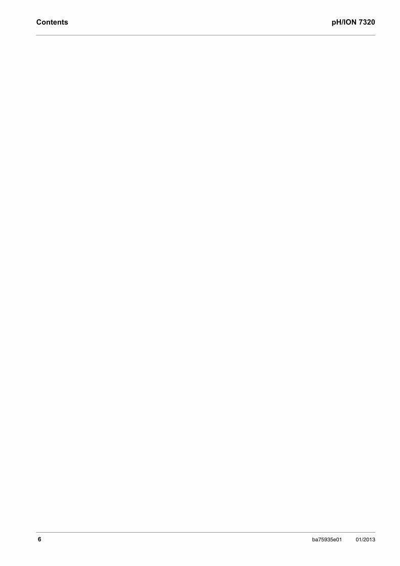
The compact precision pH meter pH/ION 7320 enables you to carry out pH measurements, ORP measurements and ion selective measurements quickly and reliably.
The pH/ION 7320 provides the maximum degree of operating comfort, reliabil-ity and measuring certainty for all applications.
The USB interface can be used for data transmission to a PC and for software updates of the meter.
1 Keypad
2 Display
3 Socket field
3
1
2
ba75935e01 01/2013 7
Overview pH/ION 7320
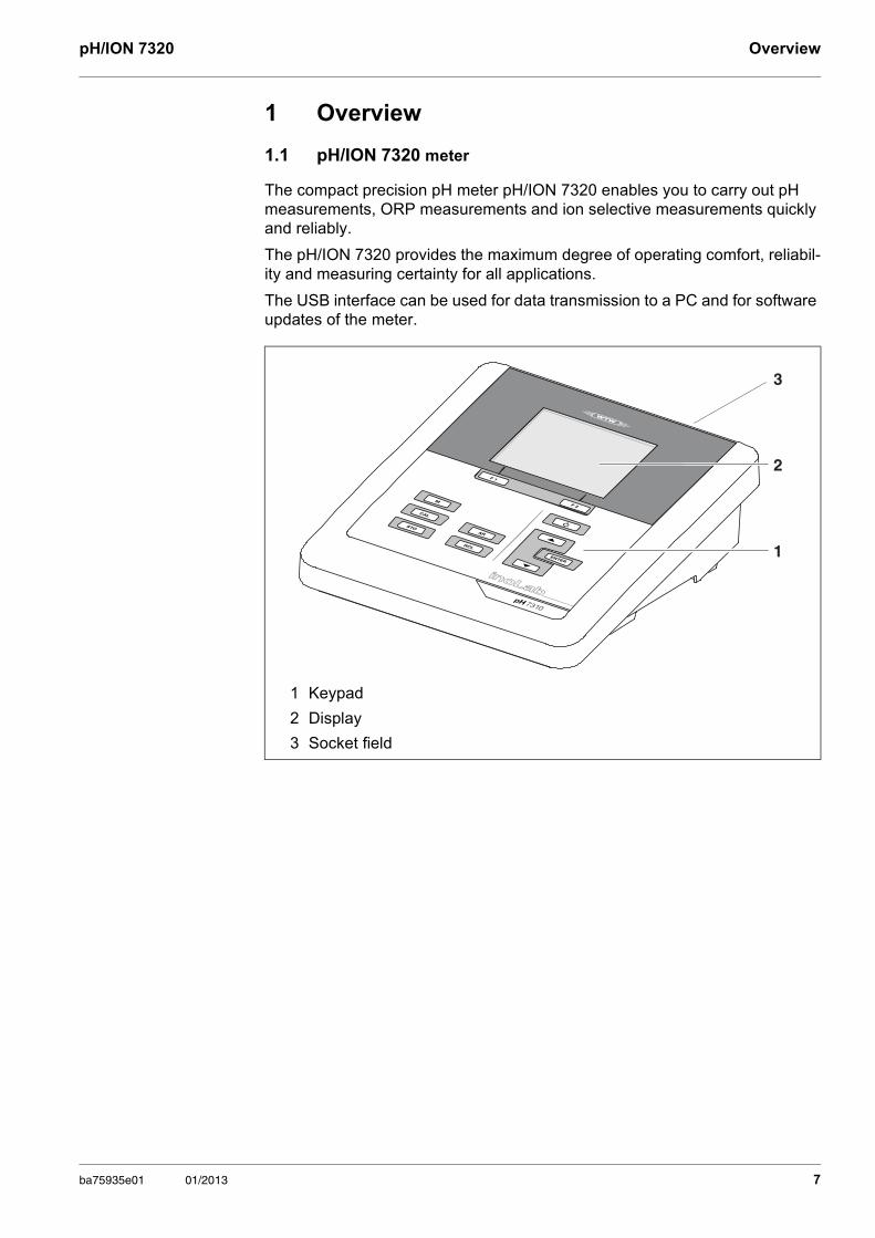
1.2 pH/ION 7320P meter
The integrated printer of the pH/ION 7320 P enables to document measure-ments according to GLP requirements.
1.3 Sensors
A measuring system ready to measure consists of the pH/ION 7320 meter and a suitable sensor.
Suitable sensors are pH electrodes, ORP electrodes and ion selective elec-trodes (ISE).
The information concerning the printer of the pH/ION 7320 P is given in a separate chapter (see section 4 PRINTER (ONLY PH/ION 7320 P), page 14).
1 Keypad
2 Display
3 Socket field
4 Printer
5 Control panel of the printer
Information on available sensors is given on the Internet and in the WTW catalog, "Laboratory and field instrumentation".
Printermodul
1
2
3
45
8 ba75935e01 01/2013
pH/ION 7320 Safety
2 Safety
2.1 Safety information
2.1.1 Safety information in the operating manual
This operating manual provides important information on the safe operation of the meter. Read this operating manual thoroughly and make yourself familiar with the meter before putting it into operation or working with it. The operating manual must be kept in the vicinity of the meter so you can always find the infor-mation you need.
Important safety instructions are highlighted in this operating manual. They are indicated by the warning symbol (triangle) in the left column. The signal word (e.g. "Caution") indicates the level of danger:
NOTE indicates a possibly dangerous situation where goods might be damaged if the actions mentioned are not taken.
2.1.2 Safety signs on the meter
Note all labels, information signs and safety symbols on the meter and in the battery compartment. A warning symbol (triangle) without text refers to safety information in this operating manual.
2.1.3 Further documents providing safety information
The following documents provide additional information, which you should observe for your safety when working with the measuring system:
• Operating manuals of sensors and other accessories
• Safety datasheets of calibration or maintenance accessories (such as buffer solutions, electrolyte solutions, etc.)
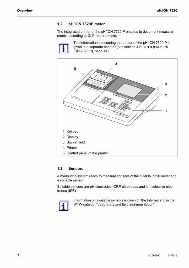
WARNINGindicates a possibly dangerous situation that can lead to seri-ous (irreversible) injury or death if the safety instruction is not followed.
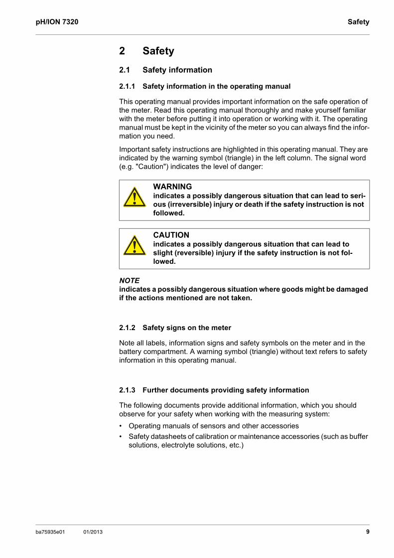
CAUTIONindicates a possibly dangerous situation that can lead to slight (reversible) injury if the safety instruction is not fol-lowed.
ba75935e01 01/2013 9
Safety pH/ION 7320
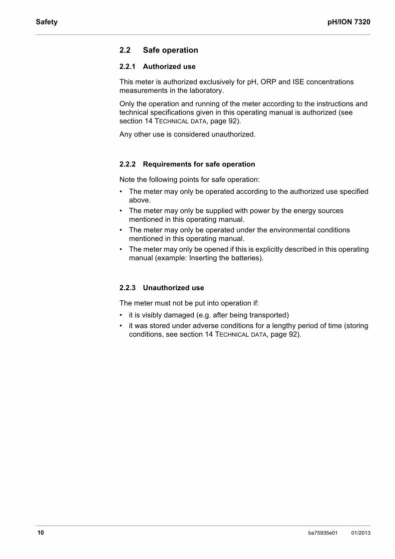
2.2 Safe operation
2.2.1 Authorized use
This meter is authorized exclusively for pH, ORP and ISE concentrations measurements in the laboratory.
Only the operation and running of the meter according to the instructions and technical specifications given in this operating manual is authorized (see section 14 TECHNICAL DATA, page 92).
Any other use is considered unauthorized.
2.2.2 Requirements for safe operation
Note the following points for safe operation:
• The meter may only be operated according to the authorized use specified above.
• The meter may only be supplied with power by the energy sources mentioned in this operating manual.
• The meter may only be operated under the environmental conditions mentioned in this operating manual.
• The meter may only be opened if this is explicitly described in this operating manual (example: Inserting the batteries).
2.2.3 Unauthorized use
The meter must not be put into operation if:
• it is visibly damaged (e.g. after being transported)
• it was stored under adverse conditions for a lengthy period of time (storing conditions, see section 14 TECHNICAL DATA, page 92).
10 ba75935e01 01/2013
pH/ION 7320 Commissioning
3 Commissioning
3.1 Scope of delivery
pH meter pH/ION 7320
4 batteries 1.5 V Mignon type AA
Power pack
USB cable (A plug on mini B plug)
Stand
Stand holder
Comprehensive operating manual
Short instructions
CD-ROM with
– USB drivers
– detailed operating manual
– Software MultiLab Importer
3.2 Power supply
The pH/ION 7320 is supplied with power in the following ways:
Mains operation with the supplied power pack
Battery operation (4 x alkaline manganese batteries, type AA)
USB operation via a connected USB-B cable
3.3 Initial commissioning
Perform the following activities:
Insert the supplied batteries
For mains operation: Connect the power pack
If necessary, mount a stand
Switch on the meter (see section 5.2 SWITCHING ON THE METER, page 19)
Set the date and time (see section 5.4.6 EXAMPLE 2 ON NAVIGATION: SETTING THE DATE AND TIME, page 25)
ba75935e01 01/2013 11
Commissioning pH/ION 7320
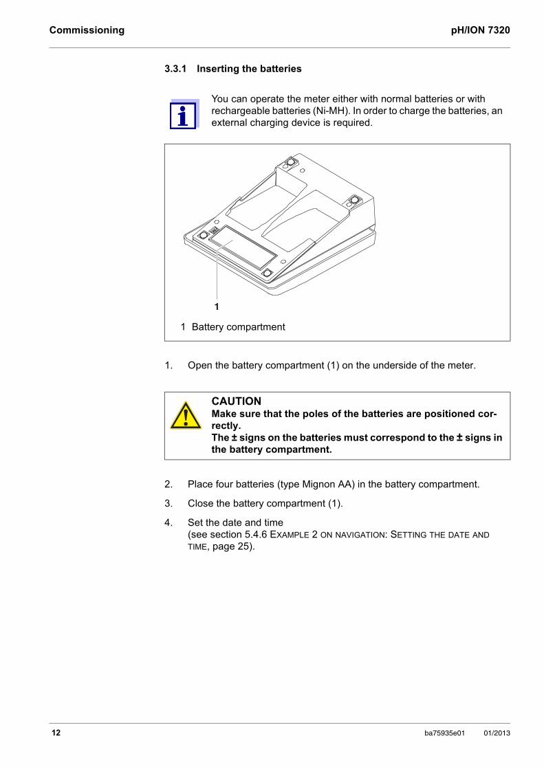
3.3.1 Inserting the batteries
You can operate the meter either with normal batteries or with rechargeable batteries (Ni-MH). In order to charge the batteries, an external charging device is required.
1 Battery compartment
1. Open the battery compartment (1) on the underside of the meter.
CAUTIONMake sure that the poles of the batteries are positioned cor-rectly. The ± signs on the batteries must correspond to the ± signs in the battery compartment.
2. Place four batteries (type Mignon AA) in the battery compartment.
3. Close the battery compartment (1).
4. Set the date and time (see section 5.4.6 EXAMPLE 2 ON NAVIGATION: SETTING THE DATE AND TIME, page 25).
1
12 ba75935e01 01/2013
pH/ION 7320 Commissioning
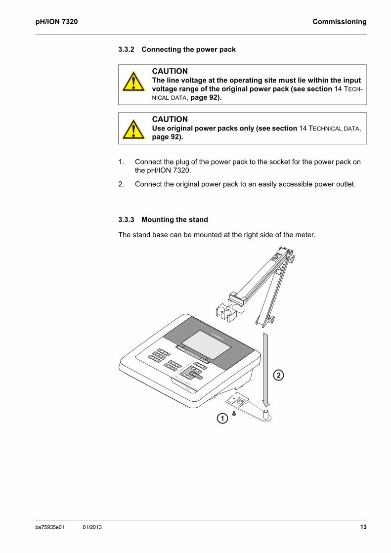
3.3.2 Connecting the power pack
3.3.3 Mounting the stand
The stand base can be mounted at the right side of the meter.
CAUTIONThe line voltage at the operating site must lie within the input voltage range of the original power pack (see section 14 TECH-NICAL DATA, page 92).
CAUTIONUse original power packs only (see section 14 TECHNICAL DATA, page 92).
1. Connect the plug of the power pack to the socket for the power pack on the pH/ION 7320.
2. Connect the original power pack to an easily accessible power outlet.
1
2
ba75935e01 01/2013 13
Printer (only pH/ION 7320 P) pH/ION 7320
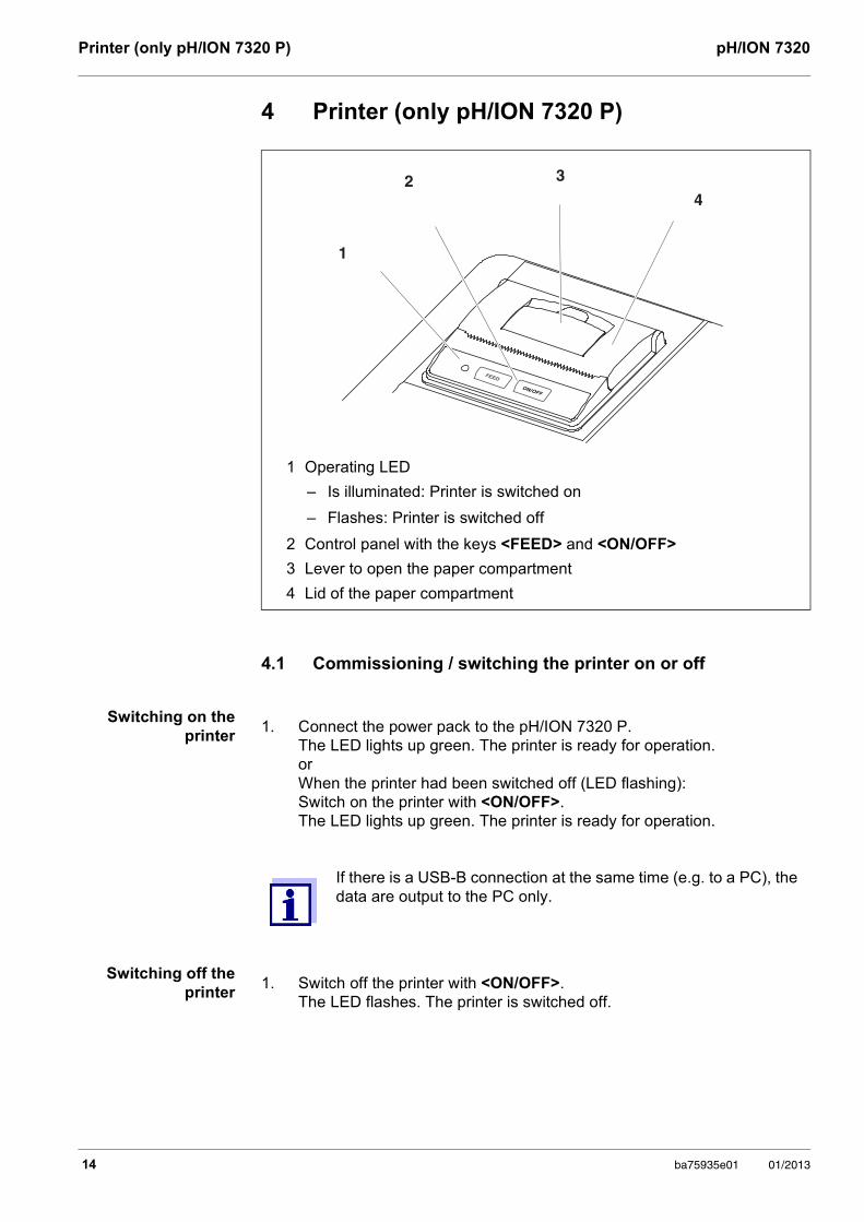
4 Printer (only pH/ION 7320 P)
4.1 Commissioning / switching the printer on or off
Switching on the printer
Switching off the printer
1 Operating LED
– Is illuminated: Printer is switched on
– Flashes: Printer is switched off
2 Control panel with the keys <FEED> and <ON/OFF>
3 Lever to open the paper compartment
4 Lid of the paper compartment
2
1
3
4
1. Connect the power pack to the pH/ION 7320 P.The LED lights up green. The printer is ready for operation.orWhen the printer had been switched off (LED flashing):Switch on the printer with <ON/OFF>.The LED lights up green. The printer is ready for operation.
If there is a USB-B connection at the same time (e.g. to a PC), the data are output to the PC only.
1. Switch off the printer with <ON/OFF>.The LED flashes. The printer is switched off.
14 ba75935e01 01/2013
pH/ION 7320 Printer (only pH/ION 7320 P)
4.2 Operation / printing
Data are only output to the printer if the following requirements are met
Data are transmitted manually or automatically (see section 11.1 OPTIONS FOR DATA TRANSMISSION, page 84)
The printer is switched on (LED illuminated)
There is no USB connection.
4.3 Printer settings
To open the Storage & config menu, press the <ENTER_> key in the measured value display. After completing the settings, switch to the measured value dis-play with <M>.
Default settings are printed in bold.
4.4 Maintenance
4.4.1 Changing the roll of paper
Menu item Possible set-ting
Description
System / Printer / Font size
12x208x167x16
Select the font size for the printer
A print sample (font of the printer) to view the available font sizes can be output with <ON/OFF_>.
System / Printer / Print test page
- The printer prints the meter informa-tion from the menu, System / Ser-vice information. The current printer settings are used for the printout.
1. Pull the lever (3) until the lid (4) of the paper compartment opens.
2. If necessary, remove any remains of the old roll of paper.
3. Insert the new roll of paper. The start of the paper should poke out of the paper compartment.
4. Close the lid (4) of the paper compartment so that it clicks into place.
5. If necessary, move the printer paper forward with <FEED>.
ba75935e01 01/2013 15
Printer (only pH/ION 7320 P) pH/ION 7320
4.5 What to do if... / printer
Integrated printer does not print
Printer operating - paper not being
printed
Integrated printer prints automatically
Use original WTW rolls of paper only.
You will find information on this in the WTW catalog LABORATORY AND FIELD INFORMATION or on the Internet.
The thermal paper will remain legible for at least 7 years if stored appropriately.
Cause Remedy
– Printer switched off (LED flashing)
– Switch on the printer (LED illuminated)
– No power pack connected – Connect the power pack
– USB cable connected – Disconnect the USB cable from the meter
– Function "store automatically at intervals" with long intervals is switched on
– Switch off the function (see section 10.2 AUTOMATIC DATA STORAGE AT INTERVALS, page 79)
– No paper available – Insert a roll of paper
Cause Remedy
– Paper inserted the wrong way up – Turn the roll of paper around and insert it with the other side upwards
Cause Remedy
– The function "store automatically at intervals" or "transmit data automatically at intervals" is switched on
– Switch off the functions (see sec-tion 10.2 AUTOMATIC DATA STORAGE AT INTERVALS, page 79 or section 11.1 OPTIONS FOR DATA TRANSMISSION, page 84)
16 ba75935e01 01/2013
pH/ION 7320 Operation
5 Operation
5.1 General operating principles
5.1.1 Keypad
In this operating manual, keys are indicated by brackets <..> . The key symbol (e.g. <ENTER>) generally indicates a short keystroke (under 2 sec) in this operating manual. A long keystroke (approx. 2 sec) is indicated by the underscore behind the key symbol (e.g. <ENTER_>).
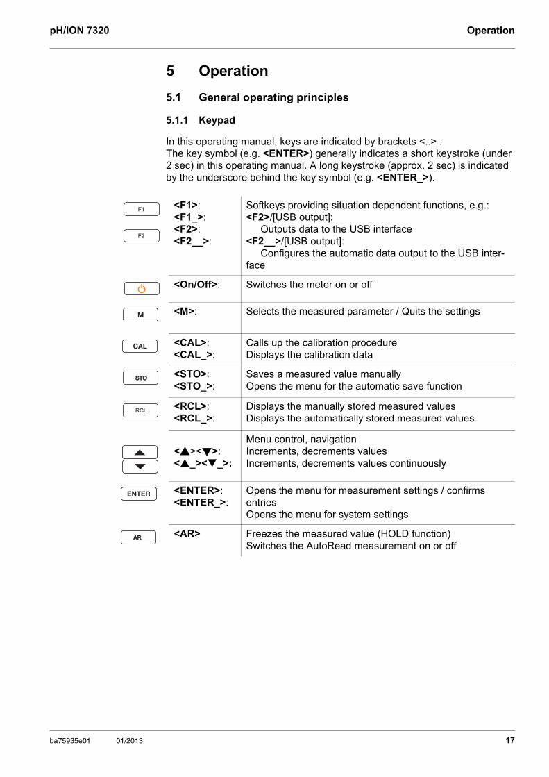
<F1>:<F1_>:<F2>:<F2__>:
Softkeys providing situation dependent functions, e.g.: <F2>/[USB output]:
Outputs data to the USB interface<F2__>/[USB output]:
Configures the automatic data output to the USB inter-face
<On/Off>: Switches the meter on or off
<M>: Selects the measured parameter / Quits the settings
<CAL>: <CAL_>:
Calls up the calibration procedure Displays the calibration data
<STO>:<STO_>:
Saves a measured value manuallyOpens the menu for the automatic save function
<RCL>: <RCL_>:
Displays the manually stored measured valuesDisplays the automatically stored measured values
<><>: <_><_>:
Menu control, navigationIncrements, decrements valuesIncrements, decrements values continuously
<ENTER>: <ENTER_>:
Opens the menu for measurement settings / confirms entriesOpens the menu for system settings
<AR> Freezes the measured value (HOLD function)Switches the AutoRead measurement on or off
F1
F2
STOSTO
RCL
ARAR
ba75935e01 01/2013 17
Operation pH/ION 7320
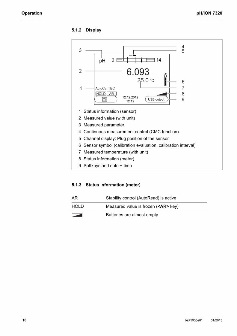
5.1.2 Display
5.1.3 Status information (meter)
1 Status information (sensor)
2 Measured value (with unit)
3 Measured parameter
4 Continuous measurement control (CMC function)
5 Channel display: Plug position of the sensor
6 Sensor symbol (calibration evaluation, calibration interval)
7 Measured temperature (with unit)
8 Status information (meter)
9 Softkeys and date + time
AR Stability control (AutoRead) is active
HOLD Measured value is frozen (<AR> key)
Batteries are almost empty
HOLD AR
25.0
6.093
pH
°C
43
2
6
7
8
9
1 AutoCal TEC
5
12.12.201212:12
USB output
18 ba75935e01 01/2013
pH/ION 7320 Operation
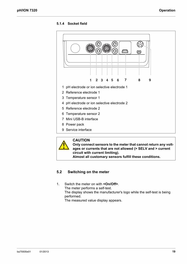
5.1.4 Socket field
5.2 Switching on the meter
1 pH electrode or ion selective electrode 1
2 Reference electrode 1
3 Temperature sensor 1
4 pH electrode or ion selective electrode 2
5 Reference electrode 2
6 Temperature sensor 2
7 Mini USB-B interface
8 Power pack
9 Service interface
CAUTIONOnly connect sensors to the meter that cannot return any volt-ages or currents that are not allowed (> SELV and > current circuit with current limiting). Almost all customary sensors fulfill these conditions.
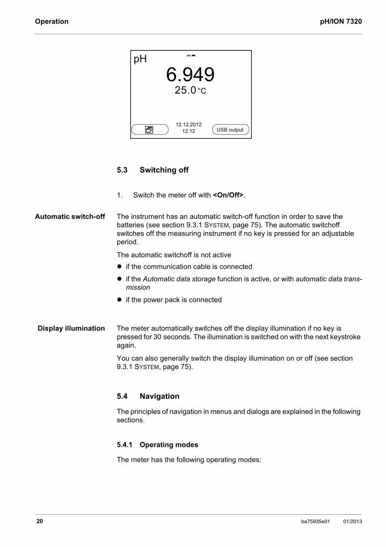
1. Switch the meter on with <On/Off>.The meter performs a self-test. The display shows the manufacturer's logo while the self-test is being performed. The measured value display appears.
1 2 3 7 8 94 5 6
ba75935e01 01/2013 19
Operation pH/ION 7320
5.3 Switching off
Automatic switch-off The instrument has an automatic switch-off function in order to save the batteries (see section 9.3.1 SYSTEM, page 75). The automatic switchoff switches off the measuring instrument if no key is pressed for an adjustable period.
The automatic switchoff is not active
if the communication cable is connected
if the Automatic data storage function is active, or with automatic data trans-mission
if the power pack is connected
Display illumination The meter automatically switches off the display illumination if no key is pressed for 30 seconds. The illumination is switched on with the next keystroke again.
You can also generally switch the display illumination on or off (see section 9.3.1 SYSTEM, page 75).
5.4 Navigation
The principles of navigation in menus and dialogs are explained in the following sections.
5.4.1 Operating modes
The meter has the following operating modes:
1. Switch the meter off with <On/Off>.
pH
6.94925.0 °C
12.12.201212:12 USB output
20 ba75935e01 01/2013
pH/ION 7320 Operation
Only those displays and functions are available in the active operating mode that are currently being required.
5.4.2 Measured value display
In the measured value display, open the setting menus with <ENTER>. The current functions of the softkeys are shown on the display.
Use <ENTER> (short pressure) to open the menu for calibration and mea-surement settings for the displayed measured parameter.
Use <ENTER_> (long keystroke (approx. 2 s) to open the Storage & config menu with the sensor-independent settings.
Use the keys of the keypad to carry out further functions such as storage or cali-bration (see section 5.1.1 KEYPAD, page 17). These functions are not available in other operating situations.
5.4.3 Menus and dialogs
The menus for settings and dialogs in procedures contain further submenus.
To select a subelement, use the <><> keys. The current selection is dis-played with a frame.
To make further settings, switch to the next higher menu level with <F1>[Back].
Use <M> to return to the measured value display.
5.4.4 Elements in menus and dialogs
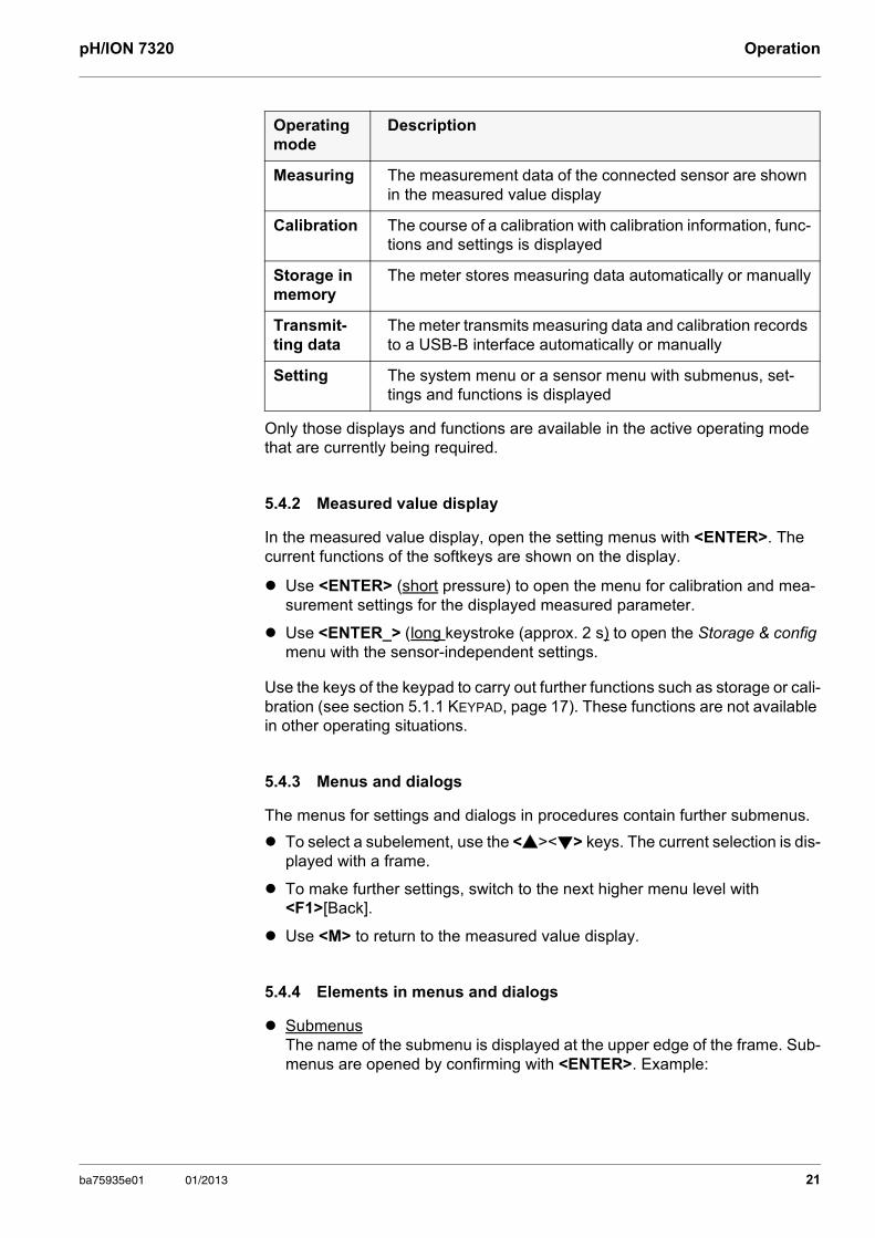
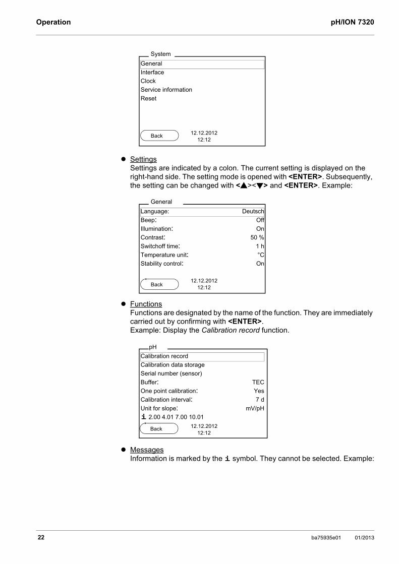
Submenus The name of the submenu is displayed at the upper edge of the frame. Sub-menus are opened by confirming with <ENTER>. Example:
Operating mode
Description
Measuring The measurement data of the connected sensor are shown in the measured value display
Calibration The course of a calibration with calibration information, func-tions and settings is displayed
Storage in memory
The meter stores measuring data automatically or manually
Transmit-ting data
The meter transmits measuring data and calibration records to a USB-B interface automatically or manually
Setting The system menu or a sensor menu with submenus, set-tings and functions is displayed
ba75935e01 01/2013 21
Operation pH/ION 7320
Settings Settings are indicated by a colon. The current setting is displayed on the right-hand side. The setting mode is opened with <ENTER>. Subsequently, the setting can be changed with <><> and <ENTER>. Example:
Functions Functions are designated by the name of the function. They are immediately carried out by confirming with <ENTER>. Example: Display the Calibration record function.
Messages Information is marked by the i symbol. They cannot be selected. Example:
General
Interface
Clock
Service information
Reset
System
12.12.201212:12
Back
Language: Deutsch
Beep: Off Illumination: On
Contrast: 50 %
Switchoff time: 1 h
Temperature unit: °C
Stability control: On
General
12.12.201212:12Back
Calibration record
Calibration data storage
Serial number (sensor)
Buffer: TEC
One point calibration: Yes
Calibration interval: 7 d
Unit for slope: mV/pH
i 2.00 4.01 7.00 10.01
pH
12.12.201212:12
Back
22 ba75935e01 01/2013
pH/ION 7320 Operation
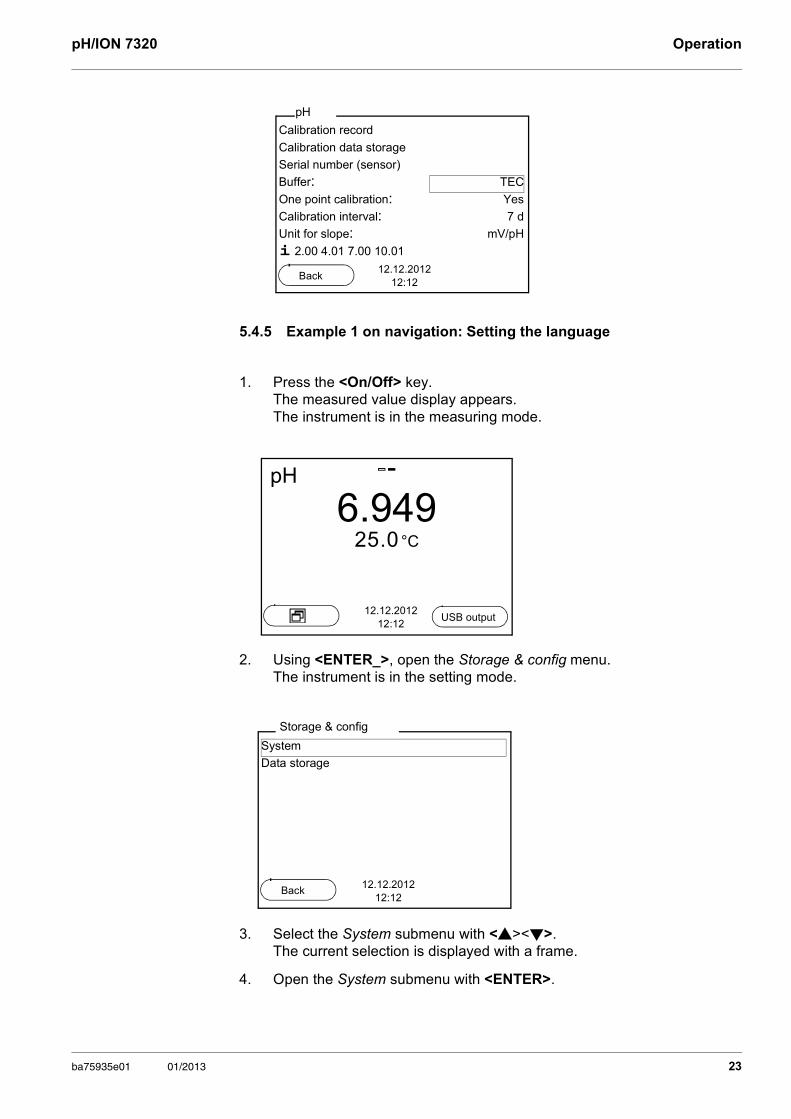
5.4.5 Example 1 on navigation: Setting the language
1. Press the <On/Off> key. The measured value display appears.The instrument is in the measuring mode.
2. Using <ENTER_>, open the Storage & config menu.The instrument is in the setting mode.
3. Select the System submenu with <><>. The current selection is displayed with a frame.
4. Open the System submenu with <ENTER>.
Calibration record
Calibration data storage
Serial number (sensor)
Buffer: TEC
One point calibration: Yes
Calibration interval: 7 d
Unit for slope: mV/pH
i 2.00 4.01 7.00 10.01
pH
12.12.201212:12
Back
pH
6.94925.0 °C
12.12.201212:12
USB output
System
Data storage
Storage & config
12.12.201212:12
Back
ba75935e01 01/2013 23
Operation pH/ION 7320
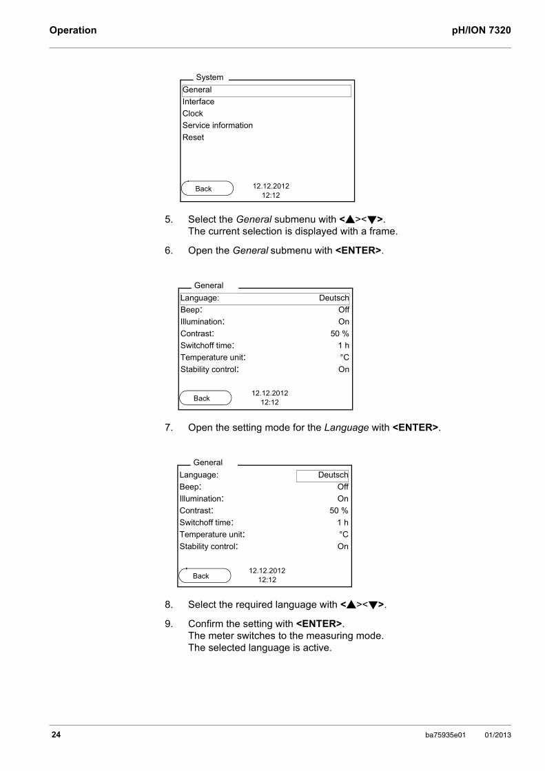
5. Select the General submenu with <><>. The current selection is displayed with a frame.
6. Open the General submenu with <ENTER>.
7. Open the setting mode for the Language with <ENTER>.
8. Select the required language with <><>.
9. Confirm the setting with <ENTER>. The meter switches to the measuring mode.The selected language is active.
General
Interface
Clock
Service information
Reset
System
12.12.201212:12
Back
Language: Deutsch
Beep: Off
Illumination: On
Contrast: 50 %
Switchoff time: 1 h
Temperature unit: °C
Stability control: On
General
12.12.201212:12Back
Language: Deutsch
Beep: Off
Illumination: On
Contrast: 50 %
Switchoff time: 1 h
Temperature unit: °C
Stability control: On
General
12.12.201212:12Back
24 ba75935e01 01/2013
pH/ION 7320 Operation
5.4.6 Example 2 on navigation: Setting the date and time
The measuring instrument has a clock with a date function. The date and time are shown in the measured value display. When storing measured values and calibrating, the current date and time are automatically stored as well.
The correct setting of the date and time and date format is important for the fol-lowing functions and displays:
Current date and time
Calibration date
Identification of stored measured values.
Therefore, check the time at regular intervals.
The date format can be switched from the display of day, month, year (dd.mm.yyyy) to the display of month, day, year (mm/dd/yyyy or mm.dd.yyyy).
After a fall of the supply voltage (empty batteries), the date and time are reset to 01.01.2011 00, 00:00 hours.
1. In the measured value display:Using <ENTER_>, open the Storage & config menu.The instrument is in the setting mode.
2. Select and confirm the System / Clock menu with <><> and <ENTER>.The setting menu for the date and time opens up.
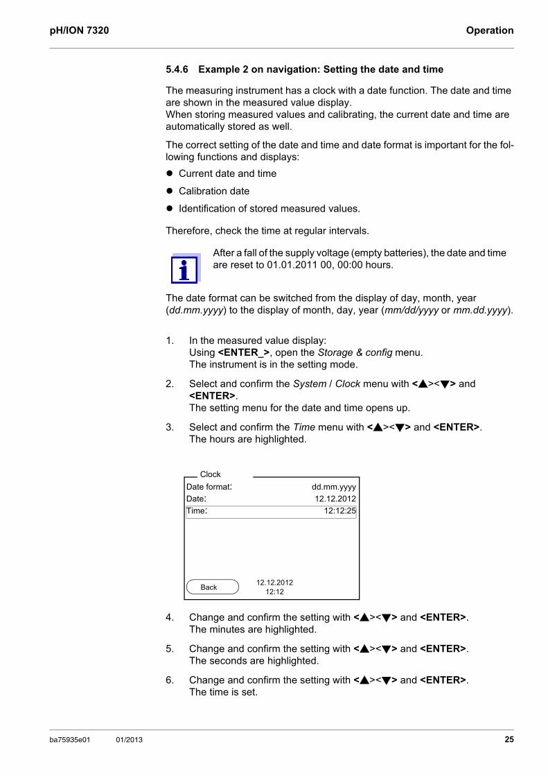
3. Select and confirm the Time menu with <><> and <ENTER>.The hours are highlighted.
4. Change and confirm the setting with <><> and <ENTER>.The minutes are highlighted.
5. Change and confirm the setting with <><> and <ENTER>.The seconds are highlighted.
6. Change and confirm the setting with <><> and <ENTER>.The time is set.
Date format: dd.mm.yyyy
Date: 12.12.2012
Time: 12:12:25
Clock
12.12.201212:12
Back
ba75935e01 01/2013 25
Operation pH/ION 7320
7. If necessary, set the Date and Date format. The setting is made similarly to that of the time.
8. To make further settings, switch to the next higher menu level with [Back]<F1>.orSwitch to the measured value display with <M>. The instrument is in the measuring mode.
26 ba75935e01 01/2013
pH/ION 7320 Operation
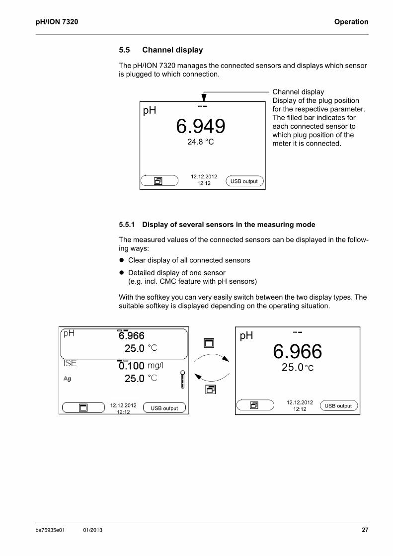
5.5 Channel display
The pH/ION 7320 manages the connected sensors and displays which sensor is plugged to which connection.
5.5.1 Display of several sensors in the measuring mode
The measured values of the connected sensors can be displayed in the follow-ing ways:
Clear display of all connected sensors
Detailed display of one sensor (e.g. incl. CMC feature with pH sensors)
With the softkey you can very easily switch between the two display types. The suitable softkey is displayed depending on the operating situation.
Channel displayDisplay of the plug positionfor the respective parameter.The filled bar indicates for each connected sensor to which plug position of the meter it is connected.
pH
6.94924.8 °C
12.12.201212:12 USB output
12.12.201212:12
USB output
pH
6.96625.0 °C
12.12.201212:12
USB output
ba75935e01 01/2013 27
pH value pH/ION 7320
6 pH value
6.1 Measuring
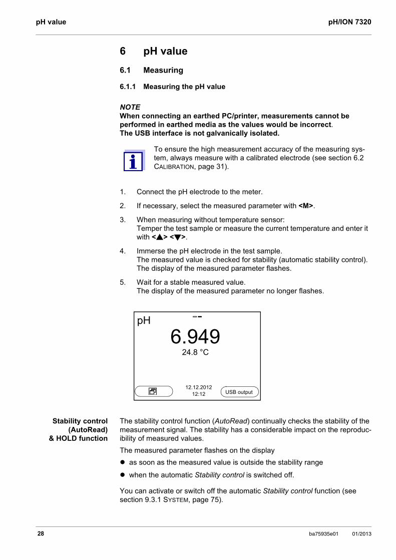
6.1.1 Measuring the pH value
NOTE When connecting an earthed PC/printer, measurements cannot be performed in earthed media as the values would be incorrect. The USB interface is not galvanically isolated.
Stability control (AutoRead)
& HOLD function
The stability control function (AutoRead) continually checks the stability of the measurement signal. The stability has a considerable impact on the reproduc-ibility of measured values.
The measured parameter flashes on the display
as soon as the measured value is outside the stability range
when the automatic Stability control is switched off.
You can activate or switch off the automatic Stability control function (see section 9.3.1 SYSTEM, page 75).
To ensure the high measurement accuracy of the measuring sys-tem, always measure with a calibrated electrode (see section 6.2 CALIBRATION, page 31).
1. Connect the pH electrode to the meter.
2. If necessary, select the measured parameter with <M>.
3. When measuring without temperature sensor: Temper the test sample or measure the current temperature and enter it with <> <>.
4. Immerse the pH electrode in the test sample.The measured value is checked for stability (automatic stability control). The display of the measured parameter flashes.
5. Wait for a stable measured value.The display of the measured parameter no longer flashes.
pH
6.94924.8 °C
12.12.201212:12 USB output
28 ba75935e01 01/2013
pH/ION 7320 pH value
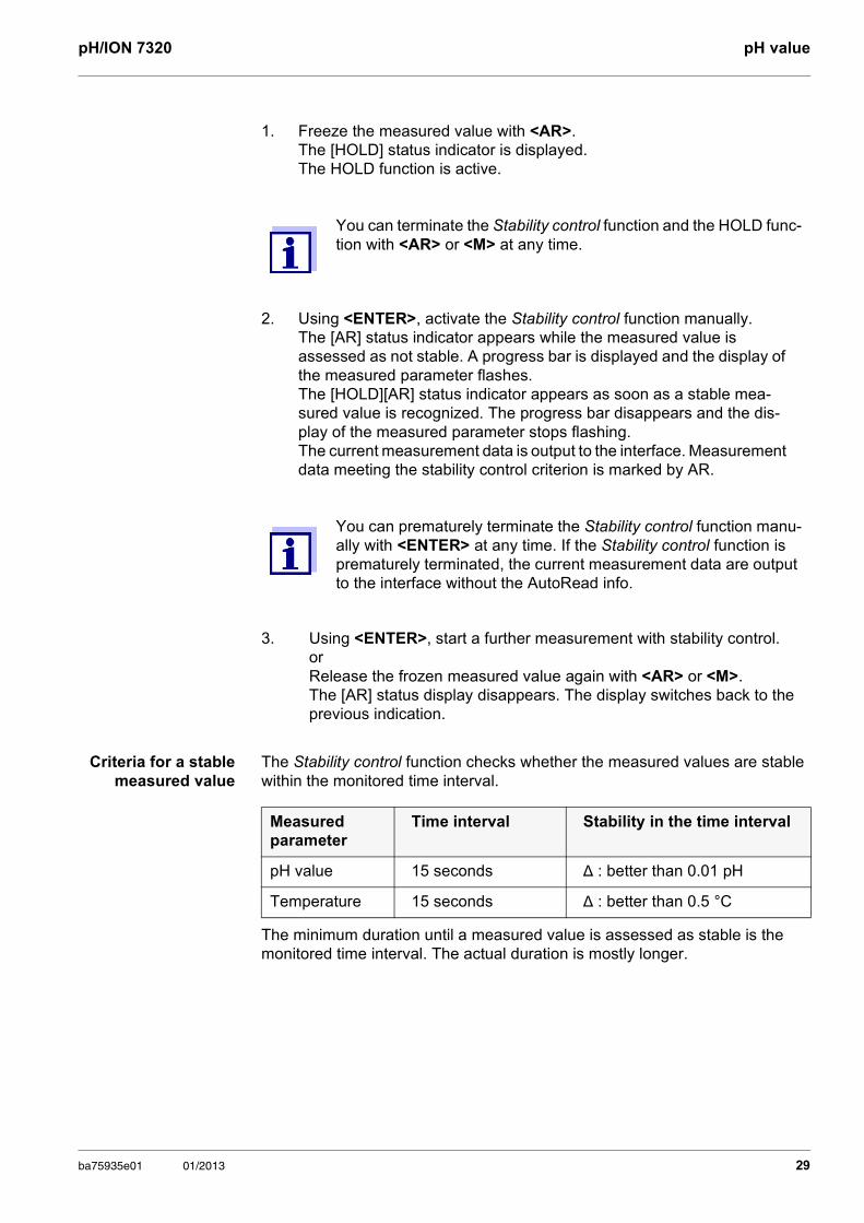
Criteria for a stable measured value
The Stability control function checks whether the measured values are stable within the monitored time interval.
The minimum duration until a measured value is assessed as stable is the monitored time interval. The actual duration is mostly longer.
1. Freeze the measured value with <AR>.The [HOLD] status indicator is displayed. The HOLD function is active.
You can terminate the Stability control function and the HOLD func-tion with <AR> or <M> at any time.
2. Using <ENTER>, activate the Stability control function manually.The [AR] status indicator appears while the measured value is assessed as not stable. A progress bar is displayed and the display of the measured parameter flashes.The [HOLD][AR] status indicator appears as soon as a stable mea-sured value is recognized. The progress bar disappears and the dis-play of the measured parameter stops flashing. The current measurement data is output to the interface. Measurement data meeting the stability control criterion is marked by AR.
You can prematurely terminate the Stability control function manu-ally with <ENTER> at any time. If the Stability control function is prematurely terminated, the current measurement data are output to the interface without the AutoRead info.
3. Using <ENTER>, start a further measurement with stability control.orRelease the frozen measured value again with <AR> or <M>.The [AR] status display disappears. The display switches back to the previous indication.
Measured parameter
Time interval Stability in the time interval
pH value 15 seconds Δ : better than 0.01 pH
Temperature 15 seconds Δ : better than 0.5 °C
ba75935e01 01/2013 29
pH value pH/ION 7320
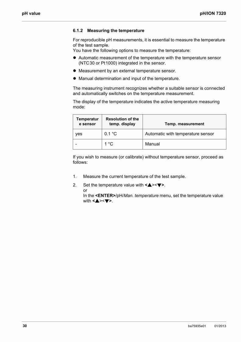
6.1.2 Measuring the temperature
For reproducible pH measurements, it is essential to measure the temperature of the test sample. You have the following options to measure the temperature:
Automatic measurement of the temperature with the temperature sensor (NTC 30 or Pt 1000) integrated in the sensor.
Measurement by an external temperature sensor.
Manual determination and input of the temperature.
The measuring instrument recognizes whether a suitable sensor is connected and automatically switches on the temperature measurement.
The display of the temperature indicates the active temperature measuring mode:
If you wish to measure (or calibrate) without temperature sensor, proceed as follows:
Temperature sensor
Resolution of the temp. display Temp. measurement
yes 0.1 °C Automatic with temperature sensor
- 1 °C Manual
1. Measure the current temperature of the test sample.
2. Set the temperature value with <><>.orIn the <ENTER>/pH/Man. temperature menu, set the temperature value with <><>.
30 ba75935e01 01/2013
pH/ION 7320 pH value
6.2 Calibration
6.2.1 Why calibrate?
pH electrodes age. This changes the zero point (asymmetry) and slope of the pH electrode. As a result, an inexact measured value is displayed. Calibration determines and stores the current values of the zero point and slope of the electrode. Thus, you should calibrate at regular intervals.
6.2.2 When do you have to calibrate?
After connecting a sensor
Routinely within the framework of the company quality assurance
When the calibration interval has expired
6.2.3 Automatic calibration (AutoCal)
Make sure that in the sensor menu, Buffer menu, the buffer set is correctly selected (see 9.1.1 SETTINGS FOR PH MEASUREMENTS, PAGE 66).
Use any one to five buffer solutions of the selected buffer set in ascending or descending order.
Below, calibration with Technical buffers (TEC) is described. When other buffer sets are used, other nominal buffer values are displayed. Apart from that, the procedure is identical.
If single-point calibration was set in the menu, the calibration proce-dure is automatically finished with the measurement of buffer solu-tion 1 and the calibration record is displayed.
1. Connect the pH electrode to the meter.
2. Keep the buffer solutions ready. When measuring without temperature sensor: Temper the buffer solutions or measure the current temperature.
3. In the measured value display, select the measured parameter pH or mV with <M>.
4. Start the calibration with <CAL>.The calibration display for the first buffer appears (voltage display).
ba75935e01 01/2013 31
pH value pH/ION 7320
Continuing with two-point calibration
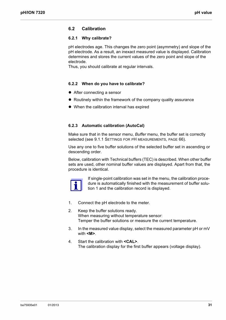
5. Thoroughly rinse the electrode with deionized water.
6. Immerse the electrode in the first buffer solution.
7. When measuring without temperature sensor:Enter the temperature of the buffer with <><>.
8. Start the measurement with <ENTER>.The measured value is checked for stability (stability control). The [AR] status indicator is displayed. A progress bar is displayed and the display of the measured parameter flashes.
9. Wait for the end of the measurement with stability control or accept the calibration value with <ENTER>. The calibration display for the next buffer appears (voltage display).
10. If necessary, finish the calibration procedure as a single-point calibration with <M>.The calibration record is displayed.
For single-point calibration, the instrument uses the Nernst slope (-59.2 mV/pH at 25 °C) and determines the zero point of the elec-trode.
pH 1
-180.024.8 °C
AutoCal TEC
12.12.201212:12
Buffer
mV
pH
-180.024.8 °C
AutoCal TEC
10.011
12.12.201212:12
AR
Buffer
mV
11. Thoroughly rinse the electrode with deionized water.
12. Immerse the electrode in the second buffer solution.
13. When measuring without temperature sensor:Enter the temperature of the buffer with <><>.
32 ba75935e01 01/2013
pH/ION 7320 pH value
Continuing with three- to five-point
calibration
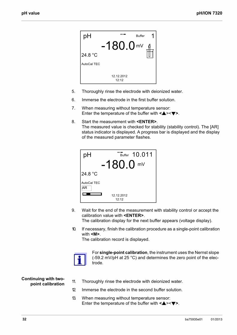
14. Start the measurement with <ENTER>.The measured value is checked for stability (stability control). The [AR] status indicator is displayed. A progress bar is displayed and the display of the measured parameter flashes.
15. Wait for the measurement with stability control to be completed or termi-nate the stability control and take over the calibration value with <ENTER>. The calibration display for the next buffer appears (voltage display).
16. If necessary, finish the calibration procedure as a two-point calibration with <M>.The calibration record is displayed.
pH
0.024.8 °C
AutoCal TEC
7.000
12.12.201212:12
AR
Buffer
mV
17. Thoroughly rinse the electrode with deionized water.
18. Immerse the electrode in the next buffer solution.
19. When measuring without temperature sensor:Enter the temperature of the buffer with <><>.
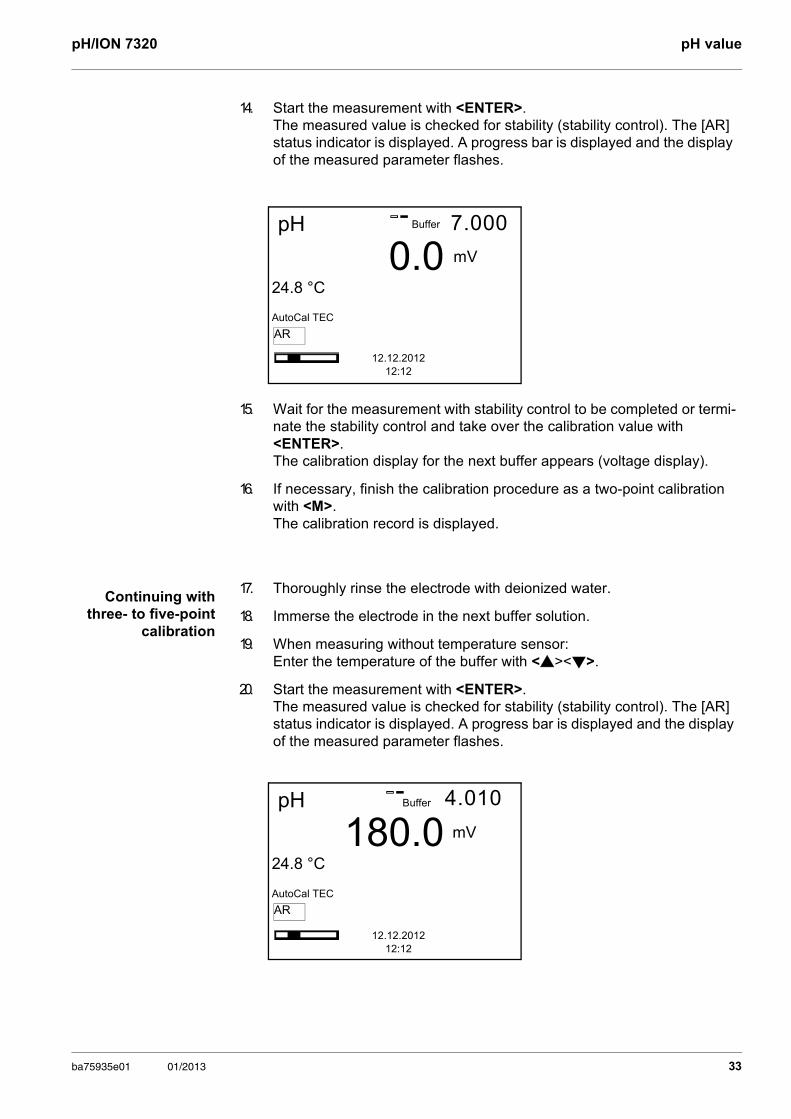
20. Start the measurement with <ENTER>.The measured value is checked for stability (stability control). The [AR] status indicator is displayed. A progress bar is displayed and the display of the measured parameter flashes.
pH
180.024.8 °C
AutoCal TEC
4.010
12.12.201212:12
AR
Buffer
mV
ba75935e01 01/2013 33
pH value pH/ION 7320
6.2.4 Manual calibration (ConCal)
Make sure that in the sensor menu, Buffer menu, the ConCal buffer set is selected (see section 9.1.1 SETTINGS FOR PH MEASUREMENTS, page 66).
Use any one to five buffer solutions in ascending or descending order.
21. Wait for the measurement with stability control to be completed or termi-nate the stability control and take over the calibration value with <ENTER>. The calibration display for the next buffer appears (voltage display).
22. If necessary, use <M> to finish calibration or Continue calibrating using the next buffer with <ENTER>.
Calibration is automatically completed after the last buffer of a buf-fer set has been measured. Then the calibration record is dis-played.
The calibration line is determined by linear regression.
If single-point calibration was set in the menu, the calibration proce-dure is automatically finished with the measurement of buffer solu-tion 1 and the calibration record is displayed.
1. Connect the pH electrode to the meter.The pH measuring window is displayed.
2. Keep the buffer solutions ready. When measuring without temperature sensor: Temper the buffer solutions or measure the current temperature.
3. In the measured value display, select the measured parameter pH or mV with <M>.
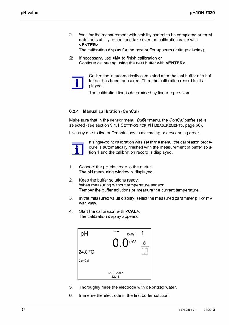
4. Start the calibration with <CAL>. The calibration display appears.
5. Thoroughly rinse the electrode with deionized water.
6. Immerse the electrode in the first buffer solution.
pH
0.024.8 °C
ConCal
1
12.12.201212:12
Buffer
mV
34 ba75935e01 01/2013
pH/ION 7320 pH value
Continuing with two-point calibration
7. When measuring without temperature sensor:Enter the temperature of the buffer with <><>.
8. Start the measurement with <ENTER>.The measured value is checked for stability (stability control). The [AR] status indicator is displayed. A progress bar is displayed and the display of the measured parameter flashes.
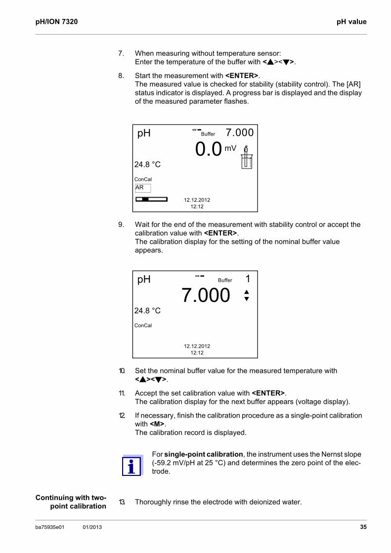
9. Wait for the end of the measurement with stability control or accept the calibration value with <ENTER>. The calibration display for the setting of the nominal buffer value appears.
10. Set the nominal buffer value for the measured temperature with <><>.
11. Accept the set calibration value with <ENTER>. The calibration display for the next buffer appears (voltage display).
12. If necessary, finish the calibration procedure as a single-point calibration with <M>.The calibration record is displayed.
For single-point calibration, the instrument uses the Nernst slope (-59.2 mV/pH at 25 °C) and determines the zero point of the elec-trode.
pH
0.024.8 °C
ConCal
7.000
12.12.201212:12
Buffer
mV
AR
pH
7.00024.8 °C
ConCal
1
12.12.201212:12
Buffer
13. Thoroughly rinse the electrode with deionized water.
ba75935e01 01/2013 35
pH value pH/ION 7320
Continuing with three- to five-point
calibration
14. Immerse the electrode in the second buffer solution.
15. When measuring without temperature sensor:Enter the temperature of the buffer with <><>.
16. Start the measurement with <ENTER>.The measured value is checked for stability (stability control). The [AR] status indicator is displayed. A progress bar is displayed and the display of the measured parameter flashes.
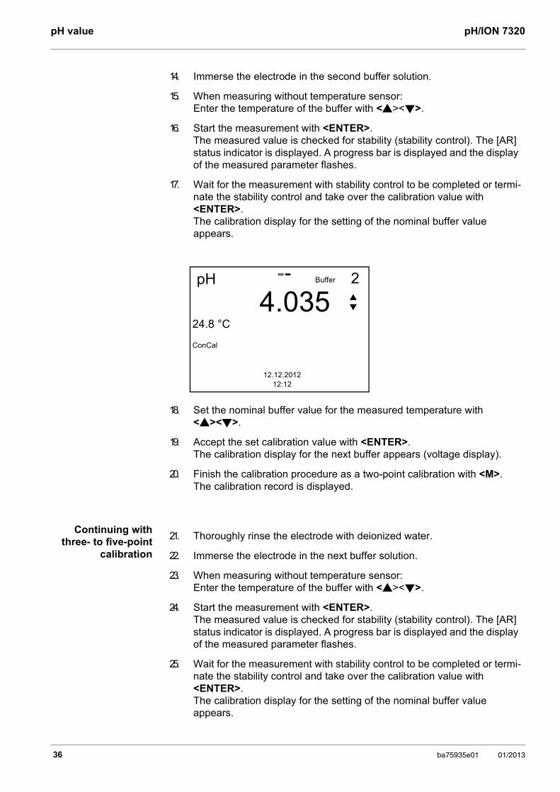
17. Wait for the measurement with stability control to be completed or termi-nate the stability control and take over the calibration value with <ENTER>. The calibration display for the setting of the nominal buffer value appears.
18. Set the nominal buffer value for the measured temperature with <><>.
19. Accept the set calibration value with <ENTER>. The calibration display for the next buffer appears (voltage display).
20. Finish the calibration procedure as a two-point calibration with <M>.The calibration record is displayed.
pH
4.03524.8 °C
ConCal
2
12.12.201212:12
Buffer
21. Thoroughly rinse the electrode with deionized water.
22. Immerse the electrode in the next buffer solution.
23. When measuring without temperature sensor:Enter the temperature of the buffer with <><>.
24. Start the measurement with <ENTER>.The measured value is checked for stability (stability control). The [AR] status indicator is displayed. A progress bar is displayed and the display of the measured parameter flashes.
25. Wait for the measurement with stability control to be completed or termi-nate the stability control and take over the calibration value with <ENTER>. The calibration display for the setting of the nominal buffer value appears.
36 ba75935e01 01/2013
pH/ION 7320 pH value
6.2.5 Calibration points
Calibration can be performed using one to five buffer solutions in any order (single-point to five-point calibration). The meter determines the following values and calculates the calibration line as follows:
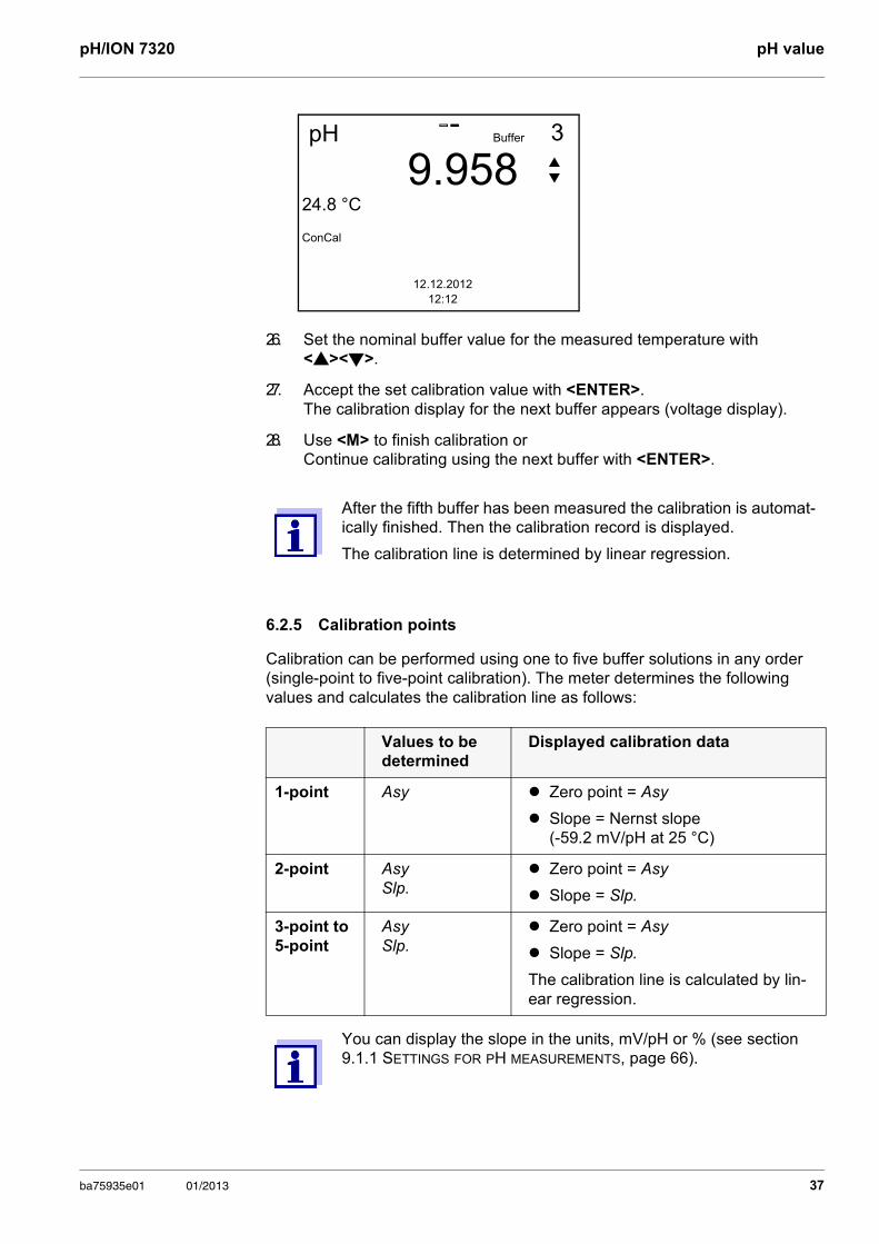
26. Set the nominal buffer value for the measured temperature with <><>.
27. Accept the set calibration value with <ENTER>. The calibration display for the next buffer appears (voltage display).
28. Use <M> to finish calibration or Continue calibrating using the next buffer with <ENTER>.
After the fifth buffer has been measured the calibration is automat-ically finished. Then the calibration record is displayed.
The calibration line is determined by linear regression.
Values to be determined
Displayed calibration data
1-point Asy Zero point = Asy
Slope = Nernst slope (-59.2 mV/pH at 25 °C)
2-point AsySlp.
Zero point = Asy
Slope = Slp.
3-point to 5-point
AsySlp.
Zero point = Asy
Slope = Slp.
The calibration line is calculated by lin-ear regression.
You can display the slope in the units, mV/pH or % (see section 9.1.1 SETTINGS FOR PH MEASUREMENTS, page 66).
pH
9.95824.8 °C
ConCal
3
12.12.201212:12
Buffer
ba75935e01 01/2013 37
pH value pH/ION 7320
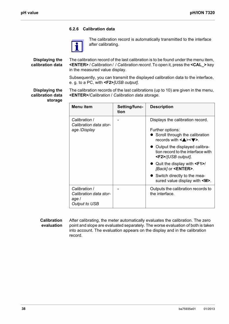
6.2.6 Calibration data
Displaying the calibration data
The calibration record of the last calibration is to be found under the menu item, <ENTER> / Calibration / / Calibration record. To open it, press the <CAL_> key in the measured value display.
Subsequently, you can transmit the displayed calibration data to the interface, e. g. to a PC, with <F2>[USB output].
Displaying thecalibration data
storage
The calibration records of the last calibrations (up to 10) are given in the menu, <ENTER>/Calibration / Calibration data storage.
Calibration evaluation
After calibrating, the meter automatically evaluates the calibration. The zero point and slope are evaluated separately. The worse evaluation of both is taken into account. The evaluation appears on the display and in the calibration record.
The calibration record is automatically transmitted to the interface after calibrating.
Menu item Setting/func-tion
Description
Calibration / Calibration data stor-age /Display
- Displays the calibration record.
Further options: Scroll through the calibration
records with <><>.
Output the displayed calibra-tion record to the interface with <F2>/[USB output].
Quit the display with <F1>/[Back] or <ENTER>.
Switch directly to the mea-sured value display with <M>.
Calibration / Calibration data stor-age / Output to USB
- Outputs the calibration records to the interface.
38 ba75935e01 01/2013
pH/ION 7320 pH value
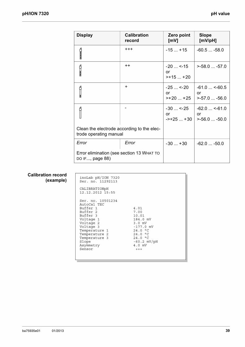
Calibration record (example)
Display Calibration record
Zero point [mV]
Slope [mV/pH]
+++ - 15 ... + 15 -60.5 ... -58.0
++ - 20 ... <-15or>+15 ... + 20
>-58.0 ... -57.0
+ - 25 ... <- 20or>+ 20 ... + 25
-61.0 ... <-60.5or>-57.0 ... -56.0
- - 30 ... <- 25or->+25 ... + 30
-62.0 ... <-61.0or>-56.0 ... -50.0
Clean the electrode according to the elec-trode operating manual
Error Error - 30 ... + 30 -62.0 ... -50.0
Error elimination (see section 13 WHAT TO DO IF..., page 88)
inoLab pH/ION 7320Ser. no. 11292113
CALIBRATIONpH12.12.2012 15:55
Ser. no. 10501234AutoCal TECBuffer 1 4.01Buffer 2 7.00Buffer 3 10.01Voltage 1 184.0 mV Voltage 2 3.0 mVVoltage 3 -177.0 mVTemperature 1 24.0 °CTemperature 2 24.0 °CTemperature 3 24.0 °CSlope -60.2 mV/pHAsymmetry 4.0 mVSensor +++
ba75935e01 01/2013 39
pH value pH/ION 7320
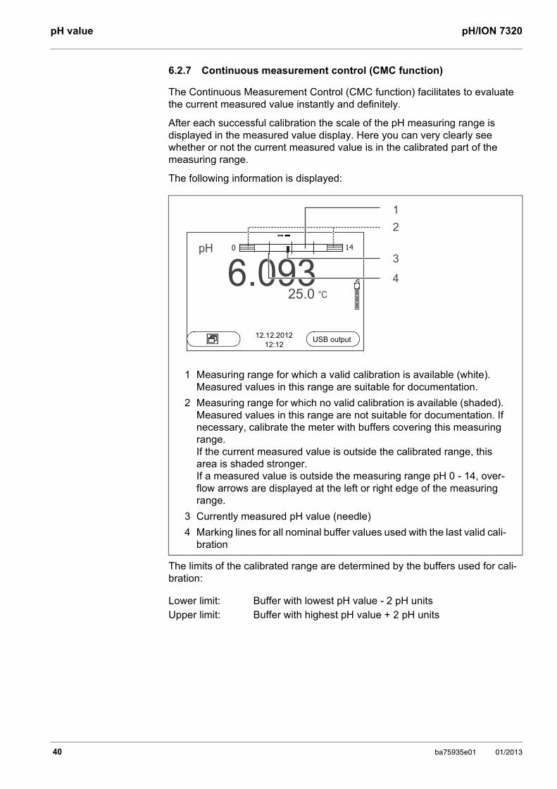
6.2.7 Continuous measurement control (CMC function)
The Continuous Measurement Control (CMC function) facilitates to evaluate the current measured value instantly and definitely.
After each successful calibration the scale of the pH measuring range is displayed in the measured value display. Here you can very clearly see whether or not the current measured value is in the calibrated part of the measuring range.
The following information is displayed:
The limits of the calibrated range are determined by the buffers used for cali-bration:
1 Measuring range for which a valid calibration is available (white). Measured values in this range are suitable for documentation.
2 Measuring range for which no valid calibration is available (shaded). Measured values in this range are not suitable for documentation. If necessary, calibrate the meter with buffers covering this measuring range. If the current measured value is outside the calibrated range, this area is shaded stronger. If a measured value is outside the measuring range pH 0 - 14, over-flow arrows are displayed at the left or right edge of the measuring range.
3 Currently measured pH value (needle)
4 Marking lines for all nominal buffer values used with the last valid cali-bration
Lower limit: Buffer with lowest pH value - 2 pH units Upper limit: Buffer with highest pH value + 2 pH units
25.06.093
1
2
3
4
pH
°C
0 14
12.12.201212:12
USB output
40 ba75935e01 01/2013
pH/ION 7320 ORP voltage
7 ORP voltage
7.1 Measuring
7.1.1 Measuring the ORP
NOTE When connecting an earthed PC/printer, measurements cannot be performed in earthed media as the values would be incorrect. The USB interface is not galvanically isolated.
Stability control (AutoRead )
The stability control function (AutoRead) continually checks the stability of the measurement signal. The stability has a considerable impact on the reproduc-ibility of measured values.
You can activate or switch off the automatic Stability control function (see section 9.3.1 SYSTEM, page 75).
The measured parameter flashes on the display
as soon as the measured value is outside the stability range
when you switch over between the measured parameters with <M>.
when the automatic Stability control is switched off.
Criteria for a stable measured value
The Stability control function checks whether the measured values are stable within the monitored time interval.
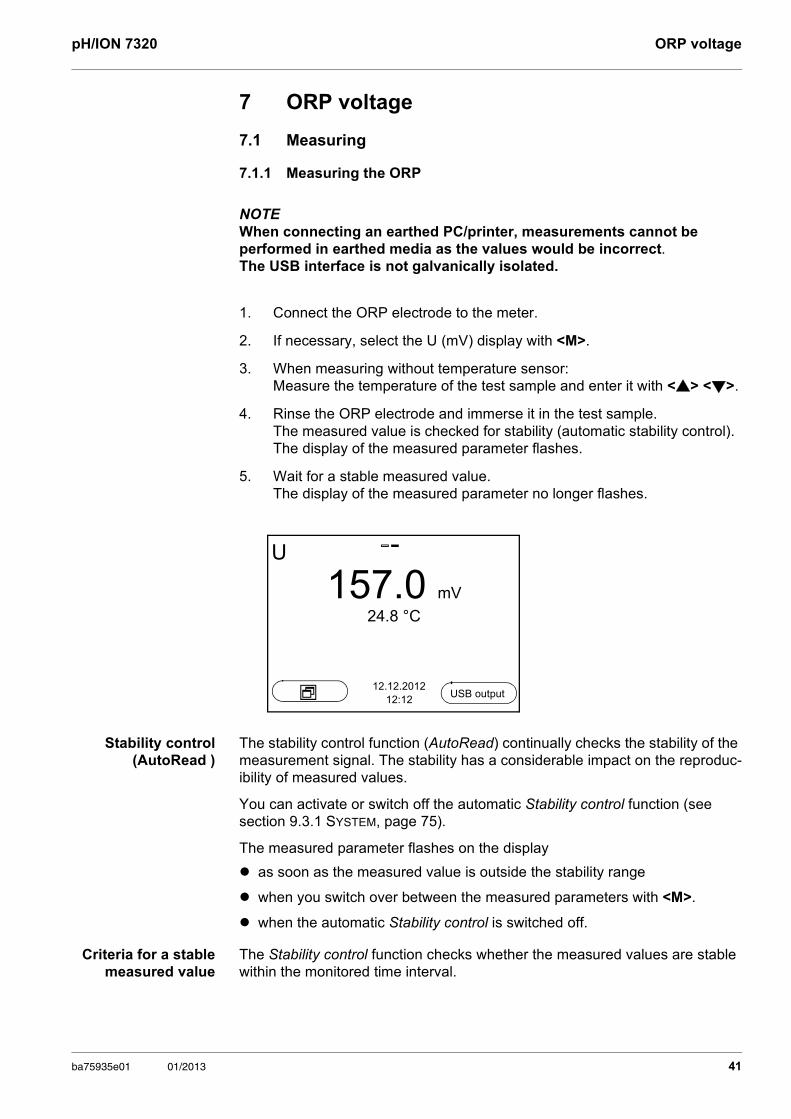
1. Connect the ORP electrode to the meter.
2. If necessary, select the U (mV) display with <M>.
3. When measuring without temperature sensor: Measure the temperature of the test sample and enter it with <> <>.
4. Rinse the ORP electrode and immerse it in the test sample.The measured value is checked for stability (automatic stability control). The display of the measured parameter flashes.
5. Wait for a stable measured value.The display of the measured parameter no longer flashes.
U
157.0 mV
24.8 °C
12.12.201212:12
USB output
ba75935e01 01/2013 41
ORP voltage pH/ION 7320
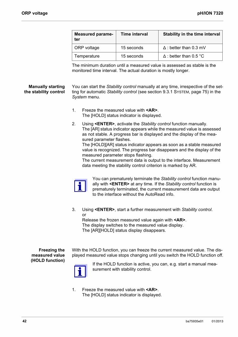
The minimum duration until a measured value is assessed as stable is the monitored time interval. The actual duration is mostly longer.
Manually starting the stability control
You can start the Stability control manually at any time, irrespective of the set-ting for automatic Stability control (see section 9.3.1 SYSTEM, page 75) in the System menu.
Freezing the measured value (HOLD function)
With the HOLD function, you can freeze the current measured value. The dis-played measured value stops changing until you switch the HOLD function off.
Measured parame-ter
Time interval Stability in the time interval
ORP voltage 15 seconds Δ : better than 0.3 mV
Temperature 15 seconds Δ : better than 0.5 °C
1. Freeze the measured value with <AR>.The [HOLD] status indicator is displayed.
2. Using <ENTER>, activate the Stability control function manually.The [AR] status indicator appears while the measured value is assessed as not stable. A progress bar is displayed and the display of the mea-sured parameter flashes.The [HOLD][AR] status indicator appears as soon as a stable measured value is recognized. The progress bar disappears and the display of the measured parameter stops flashing. The current measurement data is output to the interface. Measurement data meeting the stability control criterion is marked by AR.
You can prematurely terminate the Stability control function manu-ally with <ENTER> at any time. If the Stability control function is prematurely terminated, the current measurement data are output to the interface without the AutoRead info.
3. Using <ENTER>, start a further measurement with Stability control.orRelease the frozen measured value again with <AR>.The display switches to the measured value display. The [AR][HOLD] status display disappears.
If the HOLD function is active, you can, e.g. start a manual mea-surement with stability control.
1. Freeze the measured value with <AR>.The [HOLD] status indicator is displayed.
42 ba75935e01 01/2013
pH/ION 7320 ORP voltage
7.1.2 Measuring the relative ORP
To measure the difference of the ORPs of two solutions, you have to define the ORP of one solution as the zero point first.
AutoRead The Stability control function checks whether the measured values are stable within the monitored time interval.
2. Release the frozen measured value again with <AR>.The HOLD function is switched off.The [HOLD] status display disappears.
pH and ORP electrodes can be used to determine the relative ORP.
1. Connect the ORP electrode to the meter.
2. Prepare the reference solution for the determination of the reference point.
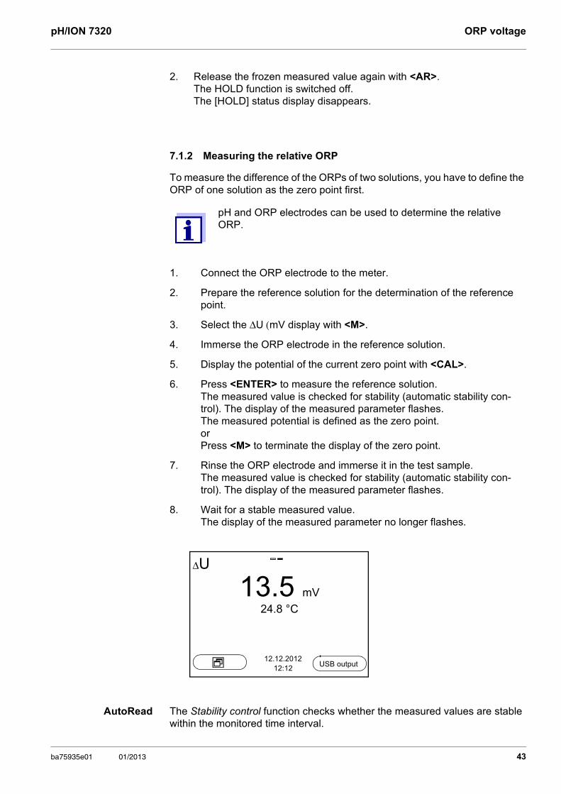
3. Select the ΔU (mV display with <M>.
4. Immerse the ORP electrode in the reference solution.
5. Display the potential of the current zero point with <CAL>.
6. Press <ENTER> to measure the reference solution. The measured value is checked for stability (automatic stability con-trol). The display of the measured parameter flashes.The measured potential is defined as the zero point.orPress <M> to terminate the display of the zero point.
7. Rinse the ORP electrode and immerse it in the test sample.The measured value is checked for stability (automatic stability con-trol). The display of the measured parameter flashes.
8. Wait for a stable measured value.The display of the measured parameter no longer flashes.
ΔU
13.5 mV
24.8 °C
12.12.201212:12
USB output
ba75935e01 01/2013 43
ORP voltage pH/ION 7320
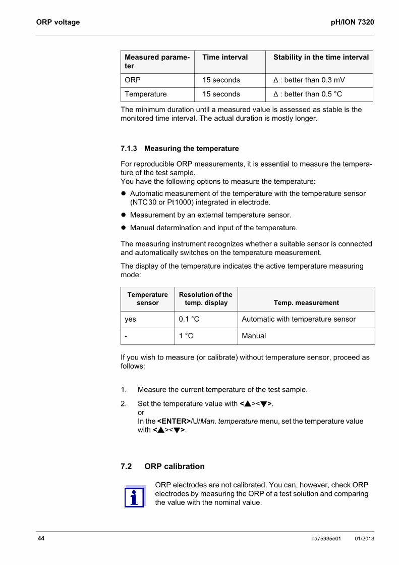
The minimum duration until a measured value is assessed as stable is the monitored time interval. The actual duration is mostly longer.
7.1.3 Measuring the temperature
For reproducible ORP measurements, it is essential to measure the tempera-ture of the test sample. You have the following options to measure the temperature:
Automatic measurement of the temperature with the temperature sensor (NTC 30 or Pt 1000) integrated in electrode.
Measurement by an external temperature sensor.
Manual determination and input of the temperature.
The measuring instrument recognizes whether a suitable sensor is connected and automatically switches on the temperature measurement.
The display of the temperature indicates the active temperature measuring mode:
If you wish to measure (or calibrate) without temperature sensor, proceed as follows:
7.2 ORP calibration
Measured parame-ter
Time interval Stability in the time interval
ORP 15 seconds Δ : better than 0.3 mV
Temperature 15 seconds Δ : better than 0.5 °C
Temperature sensor
Resolution of the temp. display Temp. measurement
yes 0.1 °C Automatic with temperature sensor
- 1 °C Manual
1. Measure the current temperature of the test sample.
2. Set the temperature value with <><>.orIn the <ENTER>/U/Man. temperature menu, set the temperature value with <><>.
ORP electrodes are not calibrated. You can, however, check ORP electrodes by measuring the ORP of a test solution and comparing the value with the nominal value.
44 ba75935e01 01/2013
pH/ION 7320 Ion concentration
8 Ion concentration
8.1 Measuring
8.1.1 Measuring the ion concentration
NOTE When connecting an earthed PC/printer, measurements cannot be performed in earthed media as the values would be incorrect. The USB interface is not galvanically isolated.
Stability control (AutoRead)
& HOLD function
The stability control function (AutoRead) continually checks the stability of the measurement signal. The stability has a considerable impact on the reproduc-ibility of measured values.
The measured parameter flashes on the display
Incorrect calibration of ion selective electrodes will result in incor-rect measured values. Calibrate regularly before measuring.
For precise ISE measurements the temperature difference between measurement and calibration should not be greater that 2 K. Therefore, adjust the temperature of the standard and measuring solutions accordingly. If the temperature difference is greater the [TpErr] warning appears in the measured value display.
1. Connect the ISE combination electrode to the meter.The pH/ISE measuring window is displayed.
2. If necessary, select the ISE display (unit, mg/l) with <M>.
3. If necessary, measure the temperature of the test sample with a ther-mometer.
4. Calibrate or check the meter with the electrode.
While no valid calibration is available, e.g. in the delivery condition, "Error" appears in the measured value display.
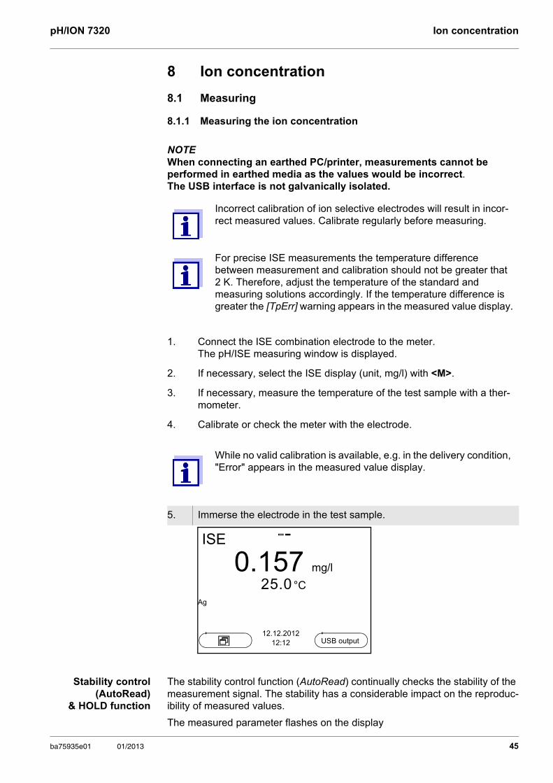
5. Immerse the electrode in the test sample.
ISE
0.157 mg/l
25.0 °CAg
12.12.201212:12 USB output
ba75935e01 01/2013 45
Ion concentration pH/ION 7320
as soon as the measured value is outside the stability range
when the automatic Stability control is switched off.
You can activate or switch off the automatic Stability control function (see section 9.1.1 SETTINGS FOR PH MEASUREMENTS, page 66).
Criteria The AutoRead criteria affect the reproducibility of the measured values. The following criteria can be adjusted:
high: highest reproducibility
medium: medium reproducibility
low: lowest reproducibility
1. Freeze the measured value with <AR>.The [HOLD] status indicator is displayed. The HOLD function is active.
You can terminate the Stability control function and the HOLD func-tion with <AR> or <M> at any time.
2. Using <ENTER>, activate the Stability control function manually.The [AR] status indicator appears while the measured value is assessed as not stable. A progress bar is displayed and the display of the measured parameter flashes.The [HOLD][AR] status indicator appears as soon as a stable mea-sured value is recognized. The progress bar disappears and the dis-play of the measured parameter stops flashing. The current measurement data is output to the interface. Measurement data meeting the stability control criterion is marked by AR.
You can prematurely terminate the Stability control function manu-ally with <ENTER> at any time. If the Stability control function is prematurely terminated, the current measurement data are output to the interface without the AutoRead info.
3. Using <ENTER>, start a further measurement with stability control.orRelease the frozen measured value again with <AR> or <M>.The [AR] status display disappears. The display switches back to the previous indication.
Increasing reproducibility also causes the response time to increase until a measured value is evaluated as stable.
46 ba75935e01 01/2013
pH/ION 7320 Ion concentration
8.1.2 Measuring the temperature
For reproducible ion-selective measurements, it is essential to measure the temperature of the test sample. You have the following options to measure the temperature:
Measurement by an external temperature sensor.
Manual determination and input of the temperature.
The measuring instrument recognizes whether a suitable sensor is connected and automatically switches on the temperature measurement.
The display of the temperature indicates the active temperature measuring mode:
If you wish to measure (or calibrate) without temperature sensor, proceed as follows:
Temperature sensor
Resolution of the temp. display Temp. measurement
yes 0.1 °C Automatic with temperature sensor
- 1 °C Manual
1. Measure the current temperature of the test sample.
2. Set the temperature value with <><>.orIn the <ENTER>/ISE/Man. temperature menu, set the temperature value with <><>.
ba75935e01 01/2013 47
Ion concentration pH/ION 7320
8.2 Calibration
8.2.1 Why calibrate?
Ion-selective electrodes age and are temperature-dependent. This changes the slope. As a result, an inexact measured value is displayed. Calibration determines the calibration line of the electrode and stores this value in the meter. Thus, you should calibrate before each measurement and at regular intervals.
8.2.2 When to calibrate?
Before any measurement if possible
After connecting another ISE electrode
When the sensor symbol flashes, e.g. after a voltage interruption (empty batteries)
8.2.3 Calibration (ISE Cal)
ISE Cal is the conventional two-point to seven-point calibration procedure that uses 2 to 7 freely selectable standard solutions. The concentration expected for the measurement determines the concentration of the calibration standards.
1. Connect the ISE combination electrode to the meter.The pH/mV/ISE measuring window is displayed.
2. Keep the standard solutions ready.
3. If necessary, measure the temperature of the standard solutions with a thermometer.
4. If necessary, change the unit of the measurement result and calibration standards in the ISE setup/Unit menu.
5. In the measured value display, select the ISE measuring window with <> <> and <M>.
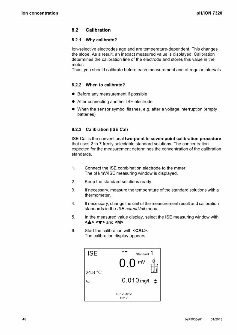
6. Start the calibration with <CAL>. The calibration display appears.
ISE
0.024.8 °C
Ag 0.010 mg/l
1
12.12.201212:12
Standard
mV
48 ba75935e01 01/2013
pH/ION 7320 Ion concentration
Continuing with two-point calibration
7. Thoroughly rinse the electrode with distilled water.
8. Immerse the electrode in standard solution 1.
9. When calibrating without temperature sensor: Measure the temperature of the standard solution using a thermom-
eter.
Use <F2>/[ T ⇅ C ] to select the setting of the temperature.
Use <> <> to set the temperature.
Use <F2>/[ T ⇅ C ] to select the setting of the concentration.
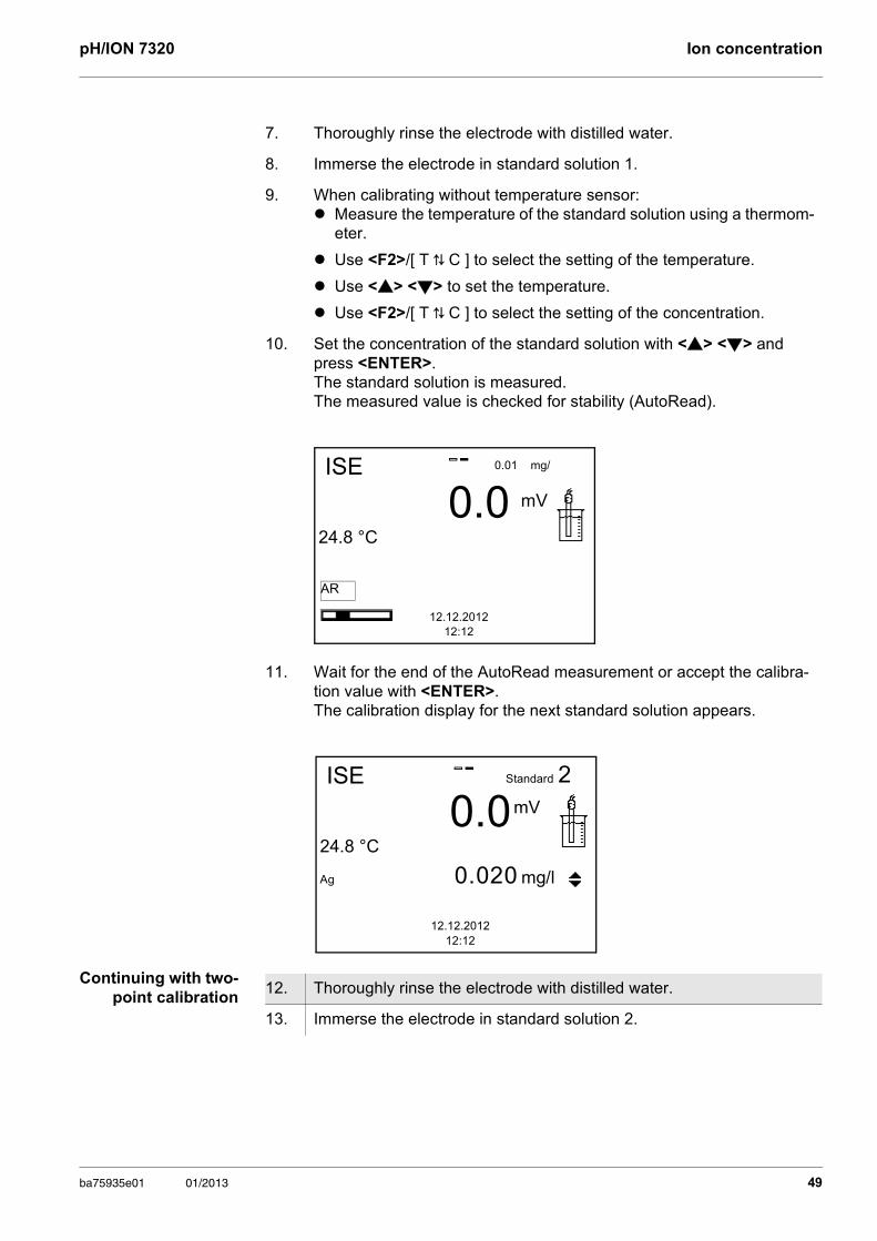
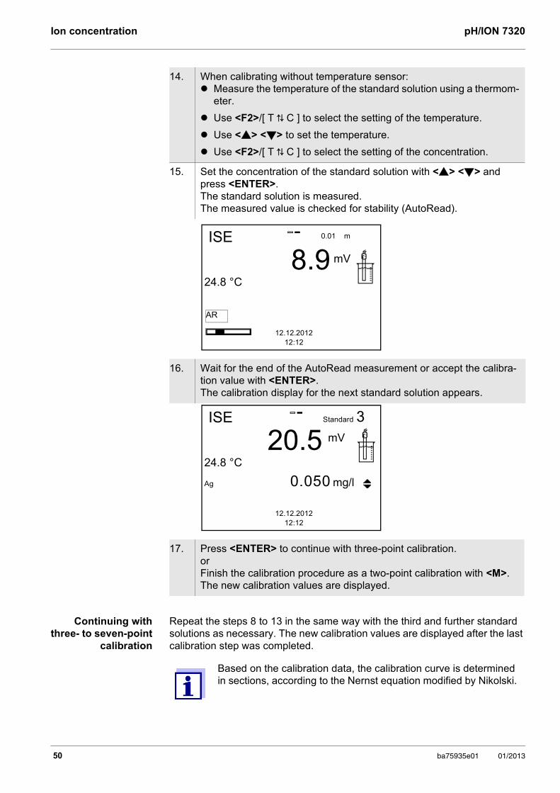
10. Set the concentration of the standard solution with <> <> and press <ENTER>. The standard solution is measured. The measured value is checked for stability (AutoRead).
11. Wait for the end of the AutoRead measurement or accept the calibra-tion value with <ENTER>. The calibration display for the next standard solution appears.
ISE
0.024.8 °C
12.12.201212:12
0.01 mg/
mV
AR
ISE
0.024.8 °C
Ag 0.020 mg/l
2
12.12.201212:12
Standard
mV
12. Thoroughly rinse the electrode with distilled water.
13. Immerse the electrode in standard solution 2.
ba75935e01 01/2013 49
Ion concentration pH/ION 7320
Continuing with three- to seven-point
calibration
Repeat the steps 8 to 13 in the same way with the third and further standard solutions as necessary. The new calibration values are displayed after the last calibration step was completed.
14. When calibrating without temperature sensor: Measure the temperature of the standard solution using a thermom-
eter.
Use <F2>/[ T ⇅ C ] to select the setting of the temperature.
Use <> <> to set the temperature.
Use <F2>/[ T ⇅ C ] to select the setting of the concentration.
15. Set the concentration of the standard solution with <> <> and press <ENTER>. The standard solution is measured. The measured value is checked for stability (AutoRead).
16. Wait for the end of the AutoRead measurement or accept the calibra-tion value with <ENTER>. The calibration display for the next standard solution appears.
17. Press <ENTER> to continue with three-point calibration.orFinish the calibration procedure as a two-point calibration with <M>. The new calibration values are displayed.
ISE
8.924.8 °C
12.12.201212:12
0.01 m
mV
AR
ISE
20.524.8 °C
Ag 0.050 mg/l
3
12.12.201212:12
Standard
mV
Based on the calibration data, the calibration curve is determined in sections, according to the Nernst equation modified by Nikolski.
50 ba75935e01 01/2013
pH/ION 7320 Ion concentration
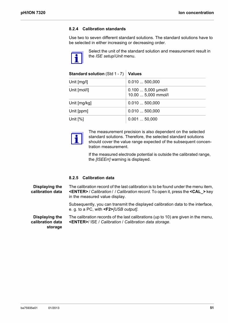
8.2.4 Calibration standards
Use two to seven different standard solutions. The standard solutions have to be selected in either increasing or decreasing order.
8.2.5 Calibration data
Displaying the calibration data
The calibration record of the last calibration is to be found under the menu item, <ENTER> / Calibration / / Calibration record. To open it, press the <CAL_> key in the measured value display.
Subsequently, you can transmit the displayed calibration data to the interface, e. g. to a PC, with <F2>[USB output].
Displaying thecalibration data
storage
The calibration records of the last calibrations (up to 10) are given in the menu, <ENTER>/ ISE / Calibration / Calibration data storage.
Select the unit of the standard solution and measurement result in the ISE setup/Unit menu.
Standard solution (Std 1 - 7) Values
Unit [mg/l] 0.010 ... 500,000
Unit [mol/l] 0.100 ... 5,000 µmol/l10.00 ... 5,000 mmol/l
Unit [mg/kg] 0.010 ... 500,000
Unit [ppm] 0.010 ... 500,000
Unit [%] 0.001 ... 50,000
The measurement precision is also dependent on the selected standard solutions. Therefore, the selected standard solutions should cover the value range expected of the subsequent concen-tration measurement.
If the measured electrode potential is outside the calibrated range, the [ISEErr] warning is displayed.
ba75935e01 01/2013 51
Ion concentration pH/ION 7320
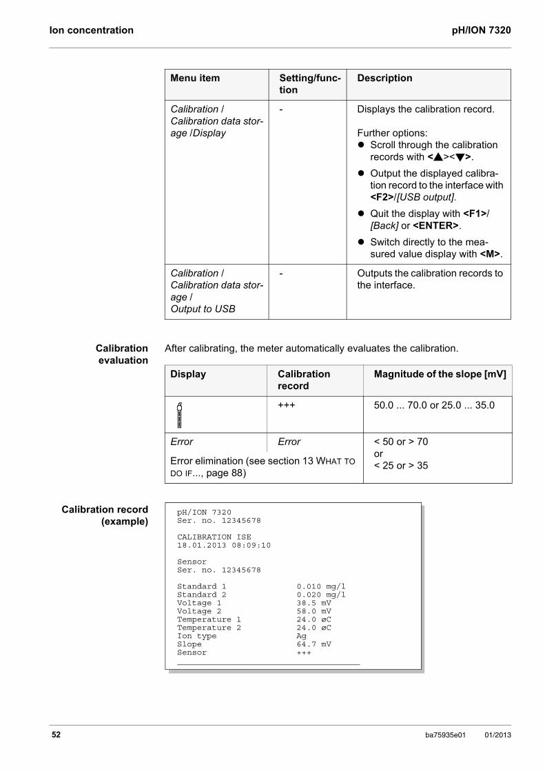
Calibration evaluation
After calibrating, the meter automatically evaluates the calibration.
Calibration record (example)
Menu item Setting/func-tion
Description
Calibration / Calibration data stor-age /Display
- Displays the calibration record.
Further options: Scroll through the calibration
records with <><>.
Output the displayed calibra-tion record to the interface with <F2>/[USB output].
Quit the display with <F1>/[Back] or <ENTER>.
Switch directly to the mea-sured value display with <M>.
Calibration / Calibration data stor-age / Output to USB
- Outputs the calibration records to the interface.
Display Calibration record
Magnitude of the slope [mV]
+++ 50.0 ... 70.0 or 25.0 ... 35.0
Error Error < 50 or > 70or < 25 or > 35Error elimination (see section 13 WHAT TO
DO IF..., page 88)
pH/ION 7320Ser. no. 12345678
CALIBRATION ISE18.01.2013 08:09:10
SensorSer. no. 12345678
Standard 1 0.010 mg/lStandard 2 0.020 mg/lVoltage 1 38.5 mVVoltage 2 58.0 mVTemperature 1 24.0 øCTemperature 2 24.0 øCIon type AgSlope 64.7 mVSensor +++_____________________________________
52 ba75935e01 01/2013
pH/ION 7320 Ion concentration
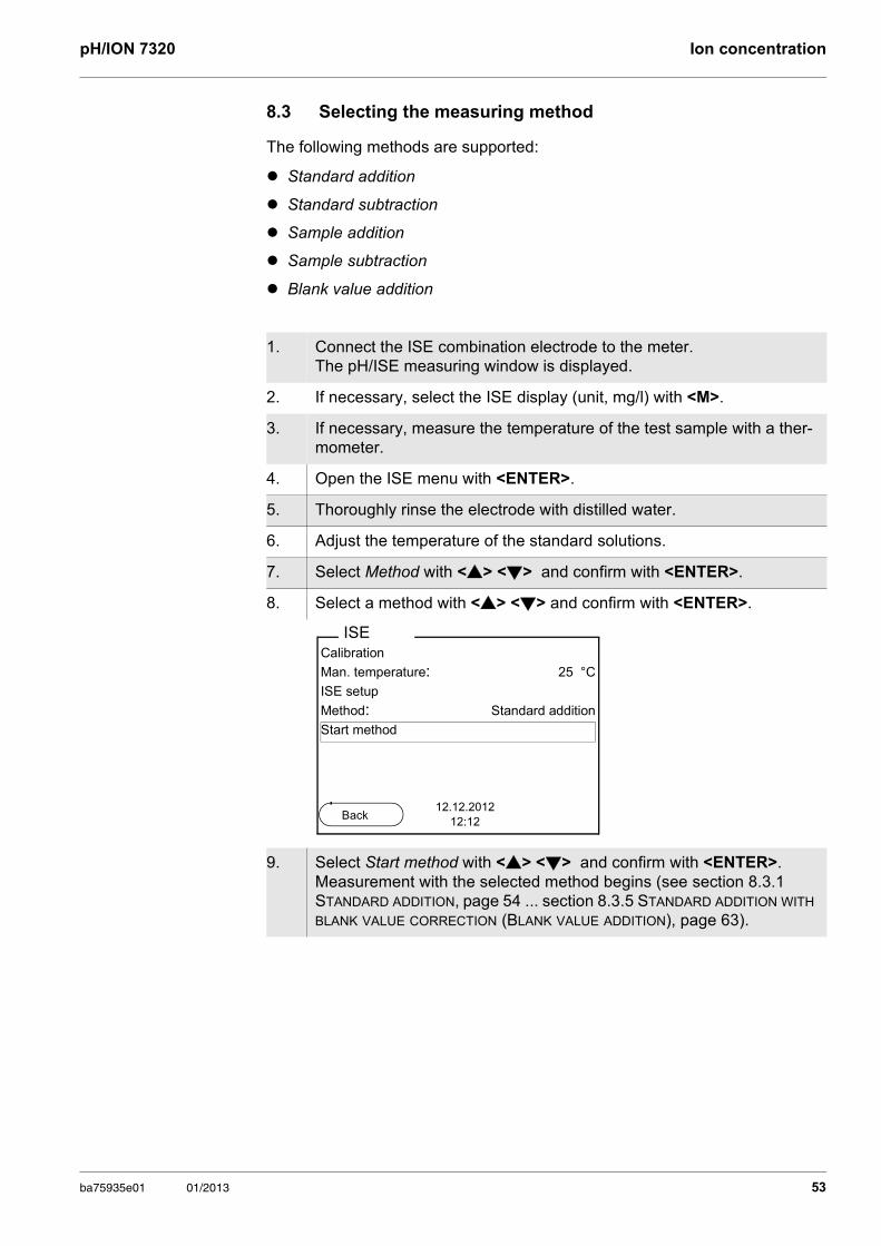
8.3 Selecting the measuring method
The following methods are supported:
Standard addition
Standard subtraction
Sample addition
Sample subtraction
Blank value addition
1. Connect the ISE combination electrode to the meter.The pH/ISE measuring window is displayed.
2. If necessary, select the ISE display (unit, mg/l) with <M>.
3. If necessary, measure the temperature of the test sample with a ther-mometer.
4. Open the ISE menu with <ENTER>.
5. Thoroughly rinse the electrode with distilled water.
6. Adjust the temperature of the standard solutions.
7. Select Method with <> <> and confirm with <ENTER>.
8. Select a method with <> <> and confirm with <ENTER>.
9. Select Start method with <> <> and confirm with <ENTER>. Measurement with the selected method begins (see section 8.3.1 STANDARD ADDITION, page 54 ... section 8.3.5 STANDARD ADDITION WITH BLANK VALUE CORRECTION (BLANK VALUE ADDITION), page 63).
Calibration
Man. temperature: 25 °C
ISE setup
Method: Standard addition
Start method
ISE
12.12.201212:12Back
ba75935e01 01/2013 53
Ion concentration pH/ION 7320
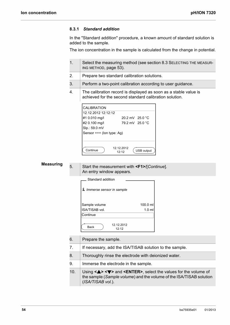
8.3.1 Standard addition
In the "Standard addition" procedure, a known amount of standard solution is added to the sample.
The ion concentration in the sample is calculated from the change in potential.
Measuring
1. Select the measuring method (see section 8.3 SELECTING THE MEASUR-ING METHOD, page 53).
2. Prepare two standard calibration solutions.
3. Perform a two-point calibration according to user guidance.
4. The calibration record is displayed as soon as a stable value is achieved for the second standard calibration solution.
CALIBRATION
12.12.2012 12:12:12
#1 0.010 mg/l 20.2 mV 25.0 °C
#2 0.100 mg/l 79.2 mV 25.0 °C
Slp.: 59.0 mV
Sensor +++ (Ion type: Ag)
12.12.201212:12Continue USB output
5. Start the measurement with <F1>/[Continue]. An entry window appears.
6. Prepare the sample.
7. If necessary, add the ISA/TISAB solution to the sample.
8. Thoroughly rinse the electrode with deionized water.
9. Immerse the electrode in the sample.
10. Using <> <> and <ENTER>, select the values for the volume of the sample (Sample volume) and the volume of the ISA/TISAB solution (ISA/TISAB vol.).
i Immerse sensor in sample
Sample volume 100.0 ml
ISA/TISAB vol. 1.0 ml
Continue
Standard addition
12.12.201212:12
Back
54 ba75935e01 01/2013
pH/ION 7320 Ion concentration
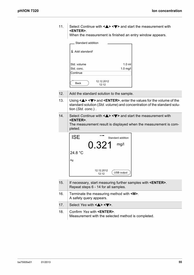
11. Select Continue with <> <> and start the measurement with <ENTER>. When the measurement is finished an entry window appears.
12. Add the standard solution to the sample.
13. Using <> <> and <ENTER>, enter the values for the volume of the standard solution (Std. volume) and concentration of the standard solu-tion (Std. conc.) .
14. Select Continue with <> <> and start the measurement with <ENTER>. The measurement result is displayed when the measurement is com-pleted.
15. If necessary, start measuring further samples with <ENTER>. Repeat steps 6 - 14 for all samples.
16. Terminate the measuring method with <M>. A safety query appears.
17. Select Yes with <> <>.
18. Confirm Yes with <ENTER>. Measurement with the selected method is completed.
i Add standard!
Std. volume 1.0 ml
Std. conc. 1.0 mg/l
Continue
Standard addition
12.12.201212:12
Back
ISE
0.32124.8 °C
Ag
12.12.201212:12
Standard addition
mg/l
USB output
ba75935e01 01/2013 55
Ion concentration pH/ION 7320
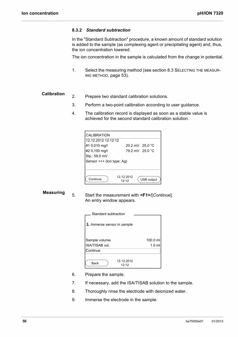
8.3.2 Standard subtraction
In the "Standard Subtraction" procedure, a known amount of standard solution is added to the sample (as complexing agent or precipitating agent) and, thus, the ion concentration lowered.
The ion concentration in the sample is calculated from the change in potential.
Calibration
Measuring
1. Select the measuring method (see section 8.3 SELECTING THE MEASUR-ING METHOD, page 53).
2. Prepare two standard calibration solutions.
3. Perform a two-point calibration according to user guidance.
4. The calibration record is displayed as soon as a stable value is achieved for the second standard calibration solution.
CALIBRATION
12.12.2012 12:12:12
#1 0.010 mg/l 20.2 mV 25.0 °C
#2 0.100 mg/l 79.2 mV 25.0 °C
Slp.: 59.0 mV
Sensor +++ (Ion type: Ag)
12.12.201212:12Continue USB output
5. Start the measurement with <F1>/[Continue]. An entry window appears.
6. Prepare the sample.
7. If necessary, add the ISA/TISAB solution to the sample.
8. Thoroughly rinse the electrode with deionized water.
9. Immerse the electrode in the sample.
i Immerse sensor in sample
Sample volume 100.0 ml
ISA/TISAB vol. 1.0 ml
Continue
Standard subtraction
12.12.201212:12Back
56 ba75935e01 01/2013
pH/ION 7320 Ion concentration
10. Using <> <> and <ENTER>, select the values for the volume of the sample (Sample volume) and the volume of the ISA/TISAB solution (ISA/TISAB vol.).
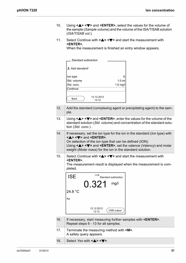
11. Select Continue with <> <> and start the measurement with <ENTER>. When the measurement is finished an entry window appears.
12. Add the standard (complexing agent or precipitating agent) to the sam-ple.
13. Using <> <> and <ENTER>, enter the values for the volume of the standard solution (Std. volume) and concentration of the standard solu-tion (Std. conc.) .
14. If necessary, set the ion type for the ion in the standard (Ion type) with <> <> and <ENTER>. On selection of the ion type that can be defined (ION): Using <> <> and <ENTER>, set the valence (Valency) and molar weight (Molar mass) for the ion in the standard solution.
15. Select Continue with <> <> and start the measurement with <ENTER>. The measurement result is displayed when the measurement is com-pleted.
16. If necessary, start measuring further samples with <ENTER>. Repeat steps 6 - 13 for all samples.
17. Terminate the measuring method with <M>. A safety query appears.
18. Select Yes with <> <>.
i Add standard!
Ion type S
Std. volume 1.0 ml
Std. conc. 1.0 mg/l
Continue
Standard subtraction
12.12.201212:12Back
ISE
0.32124.8 °C
Ag
12.12.201212:12
Standard subtraction
mg/l
USB output
ba75935e01 01/2013 57
Ion concentration pH/ION 7320
19. Confirm Yes with <ENTER>. Measurement with the selected method is completed.
58 ba75935e01 01/2013
pH/ION 7320 Ion concentration
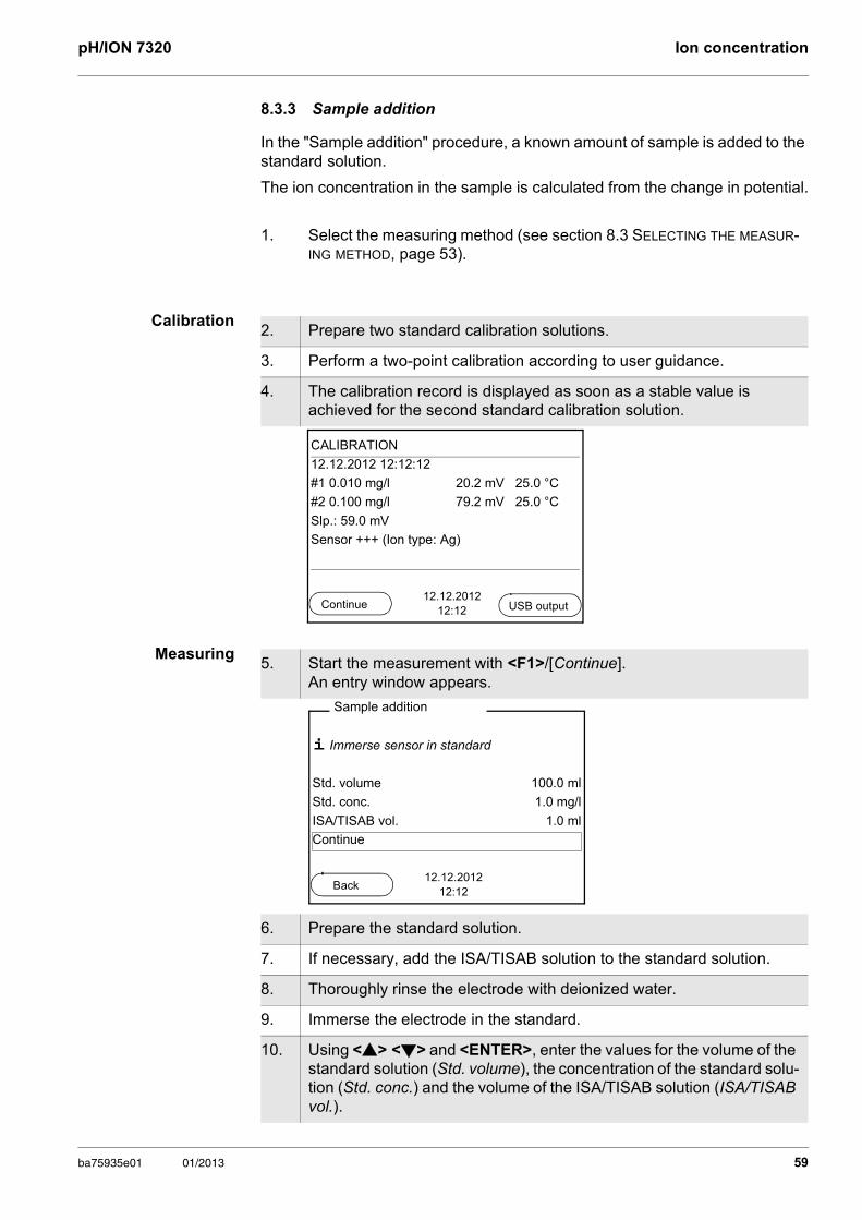
8.3.3 Sample addition
In the "Sample addition" procedure, a known amount of sample is added to the standard solution.
The ion concentration in the sample is calculated from the change in potential.
Calibration
Measuring
1. Select the measuring method (see section 8.3 SELECTING THE MEASUR-ING METHOD, page 53).
2. Prepare two standard calibration solutions.
3. Perform a two-point calibration according to user guidance.
4. The calibration record is displayed as soon as a stable value is achieved for the second standard calibration solution.
CALIBRATION
12.12.2012 12:12:12
#1 0.010 mg/l 20.2 mV 25.0 °C
#2 0.100 mg/l 79.2 mV 25.0 °C
Slp.: 59.0 mV
Sensor +++ (Ion type: Ag)
12.12.201212:12Continue USB output
5. Start the measurement with <F1>/[Continue]. An entry window appears.
6. Prepare the standard solution.
7. If necessary, add the ISA/TISAB solution to the standard solution.
8. Thoroughly rinse the electrode with deionized water.
9. Immerse the electrode in the standard.
10. Using <> <> and <ENTER>, enter the values for the volume of the standard solution (Std. volume), the concentration of the standard solu-tion (Std. conc.) and the volume of the ISA/TISAB solution (ISA/TISAB vol.).
i Immerse sensor in standard
Std. volume 100.0 ml
Std. conc. 1.0 mg/l
ISA/TISAB vol. 1.0 ml
Continue
Sample addition
12.12.201212:12
Back
ba75935e01 01/2013 59
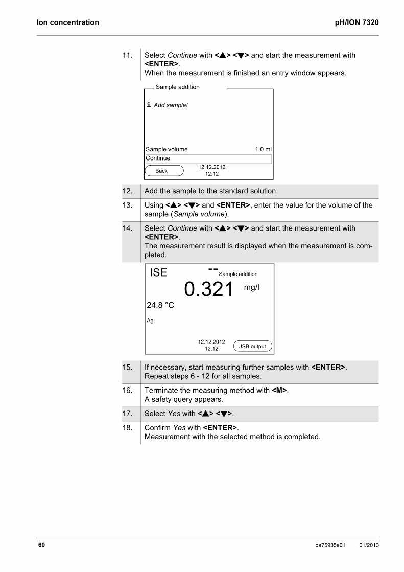
Ion concentration pH/ION 7320
11. Select Continue with <> <> and start the measurement with <ENTER>. When the measurement is finished an entry window appears.
12. Add the sample to the standard solution.
13. Using <> <> and <ENTER>, enter the value for the volume of the sample (Sample volume).
14. Select Continue with <> <> and start the measurement with <ENTER>. The measurement result is displayed when the measurement is com-pleted.
15. If necessary, start measuring further samples with <ENTER>. Repeat steps 6 - 12 for all samples.
16. Terminate the measuring method with <M>. A safety query appears.
17. Select Yes with <> <>.
18. Confirm Yes with <ENTER>. Measurement with the selected method is completed.
i Add sample!
Sample volume 1.0 ml
Continue
Sample addition
12.12.201212:12
Back
ISE
0.32124.8 °C
Ag
12.12.201212:12
Sample addition
mg/l
USB output
60 ba75935e01 01/2013
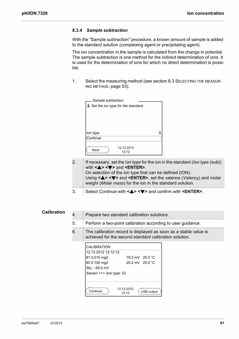
pH/ION 7320 Ion concentration
8.3.4 Sample subtraction
With the "Sample subtraction" procedure, a known amount of sample is added to the standard solution (complexing agent or precipitating agent).
The ion concentration in the sample is calculated from the change in potential. The sample subtraction is one method for the indirect determination of ions. It is used for the determination of ions for which no direct determination is possi-ble.
Calibration
1. Select the measuring method (see section 8.3 SELECTING THE MEASUR-ING METHOD, page 53).
2. If necessary, set the ion type for the ion in the standard (Ion type (sub)) with <> <> and <ENTER>. On selection of the ion type that can be defined (ION): Using <> <> and <ENTER>, set the valence (Valency) and molar weight (Molar mass) for the ion in the standard solution.
3. Select Continue with <> <> and confirm with <ENTER>.
i Set the ion type for the standard.
Ion type S
Continue
Sample subtraction
12.12.201212:12
Back
4. Prepare two standard calibration solutions.
5. Perform a two-point calibration according to user guidance.
6. The calibration record is displayed as soon as a stable value is achieved for the second standard calibration solution.
CALIBRATION
12.12.2012 12:12:12
#1 0.010 mg/l 79.2 mV 25.0 °C
#2 0.100 mg/l 20.2 mV 25.0 °C
Slp.: -59.0 mV
Sensor +++ (Ion type: S)
12.12.201212:12
Continue USB output
ba75935e01 01/2013 61
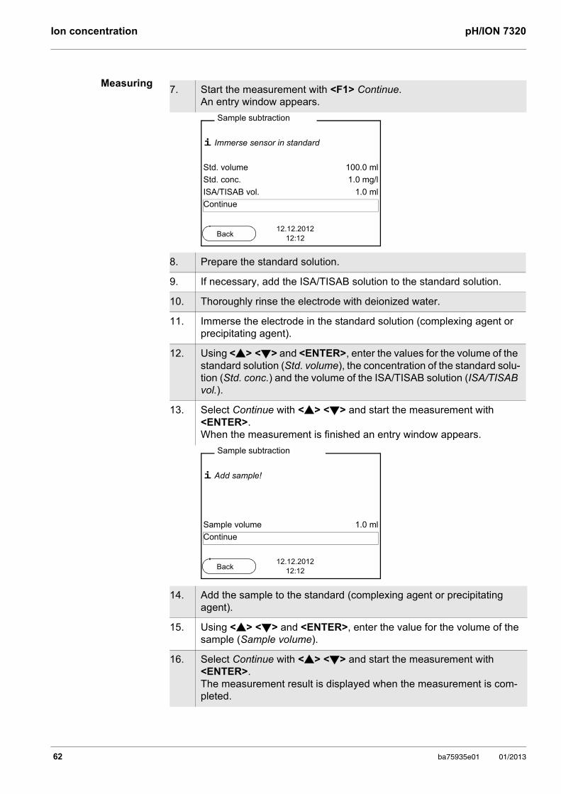
Ion concentration pH/ION 7320
Measuring7. Start the measurement with <F1> Continue.
An entry window appears.
8. Prepare the standard solution.
9. If necessary, add the ISA/TISAB solution to the standard solution.
10. Thoroughly rinse the electrode with deionized water.
11. Immerse the electrode in the standard solution (complexing agent or precipitating agent).
12. Using <> <> and <ENTER>, enter the values for the volume of the standard solution (Std. volume), the concentration of the standard solu-tion (Std. conc.) and the volume of the ISA/TISAB solution (ISA/TISAB vol.).
13. Select Continue with <> <> and start the measurement with <ENTER>. When the measurement is finished an entry window appears.
14. Add the sample to the standard (complexing agent or precipitating agent).
15. Using <> <> and <ENTER>, enter the value for the volume of the sample (Sample volume).
16. Select Continue with <> <> and start the measurement with <ENTER>. The measurement result is displayed when the measurement is com-pleted.
i Immerse sensor in standard
Std. volume 100.0 ml
Std. conc. 1.0 mg/l
ISA/TISAB vol. 1.0 ml
Continue
Sample subtraction
12.12.201212:12
Back
i Add sample!
Sample volume 1.0 ml
Continue
Sample subtraction
12.12.201212:12
Back
62 ba75935e01 01/2013
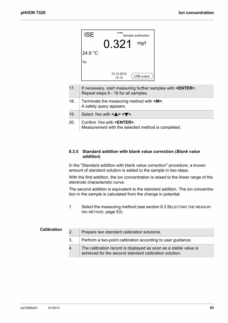
pH/ION 7320 Ion concentration
8.3.5 Standard addition with blank value correction (Blank value addition)
In the "Standard addition with blank value correction" procedure, a known amount of standard solution is added to the sample in two steps.
With the first addition, the ion concentration is raised to the linear range of the electrode characteristic curve.
The second addition is equivalent to the standard addition. The ion concentra-tion in the sample is calculated from the change in potential.
Calibration
17. If necessary, start measuring further samples with <ENTER>. Repeat steps 8 - 16 for all samples.
18. Terminate the measuring method with <M>. A safety query appears.
19. Select Yes with <> <>.
20. Confirm Yes with <ENTER>. Measurement with the selected method is completed.
1. Select the measuring method (see section 8.3 SELECTING THE MEASUR-ING METHOD, page 53).
ISE
0.32124.8 °C
Ag
12.12.201212:12
Sample subtraction
mg/l
USB output
2. Prepare two standard calibration solutions.
3. Perform a two-point calibration according to user guidance.
4. The calibration record is displayed as soon as a stable value is achieved for the second standard calibration solution.
ba75935e01 01/2013 63
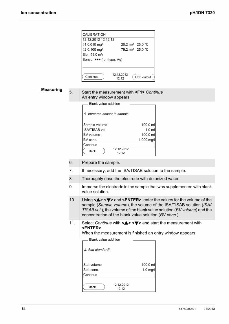
Ion concentration pH/ION 7320
Measuring
CALIBRATION
12.12.2012 12:12:12
#1 0.010 mg/l 20.2 mV 25.0 °C
#2 0.100 mg/l 79.2 mV 25.0 °C
Slp.: 59.0 mV
Sensor +++ (Ion type: Ag)
12.12.201212:12Continue USB output
5. Start the measurement with <F1> Continue An entry window appears.
6. Prepare the sample.
7. If necessary, add the ISA/TISAB solution to the sample.
8. Thoroughly rinse the electrode with deionized water.
9. Immerse the electrode in the sample that was supplemented with blank value solution.
10. Using <> <> and <ENTER>, enter the values for the volume of the sample (Sample volume), the volume of the ISA/TISAB solution (ISA/TISAB vol.), the volume of the blank value solution (BV volume) and the concentration of the blank value solution (BV conc.).
11. Select Continue with <> <> and start the measurement with <ENTER>. When the measurement is finished an entry window appears.
i Immerse sensor in sample
Sample volume 100.0 ml
ISA/TISAB vol. 1.0 ml
BV volume 100.0 ml
BV conc. 1.000 mg/l
Continue
Blank value addition
12.12.201212:12
Back
i Add standard!
Std. volume 100.0 ml
Std. conc. 1.0 mg/l
Continue
Blank value addition
12.12.201212:12
Back
64 ba75935e01 01/2013
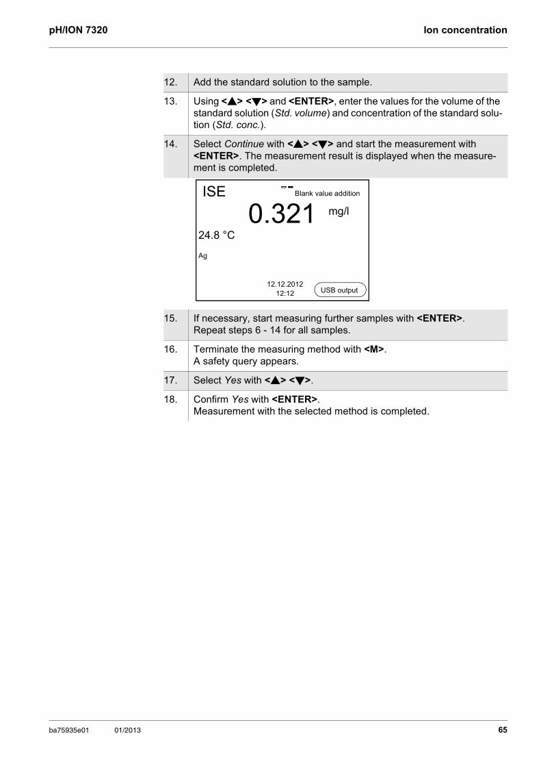
pH/ION 7320 Ion concentration
12. Add the standard solution to the sample.
13. Using <> <> and <ENTER>, enter the values for the volume of the standard solution (Std. volume) and concentration of the standard solu-tion (Std. conc.).
14. Select Continue with <> <> and start the measurement with <ENTER>. The measurement result is displayed when the measure-ment is completed.
15. If necessary, start measuring further samples with <ENTER>. Repeat steps 6 - 14 for all samples.
16. Terminate the measuring method with <M>. A safety query appears.
17. Select Yes with <> <>.
18. Confirm Yes with <ENTER>. Measurement with the selected method is completed.
ISE
0.32124.8 °C
Ag
12.12.201212:12
Blank value addition
mg/l
USB output
ba75935e01 01/2013 65
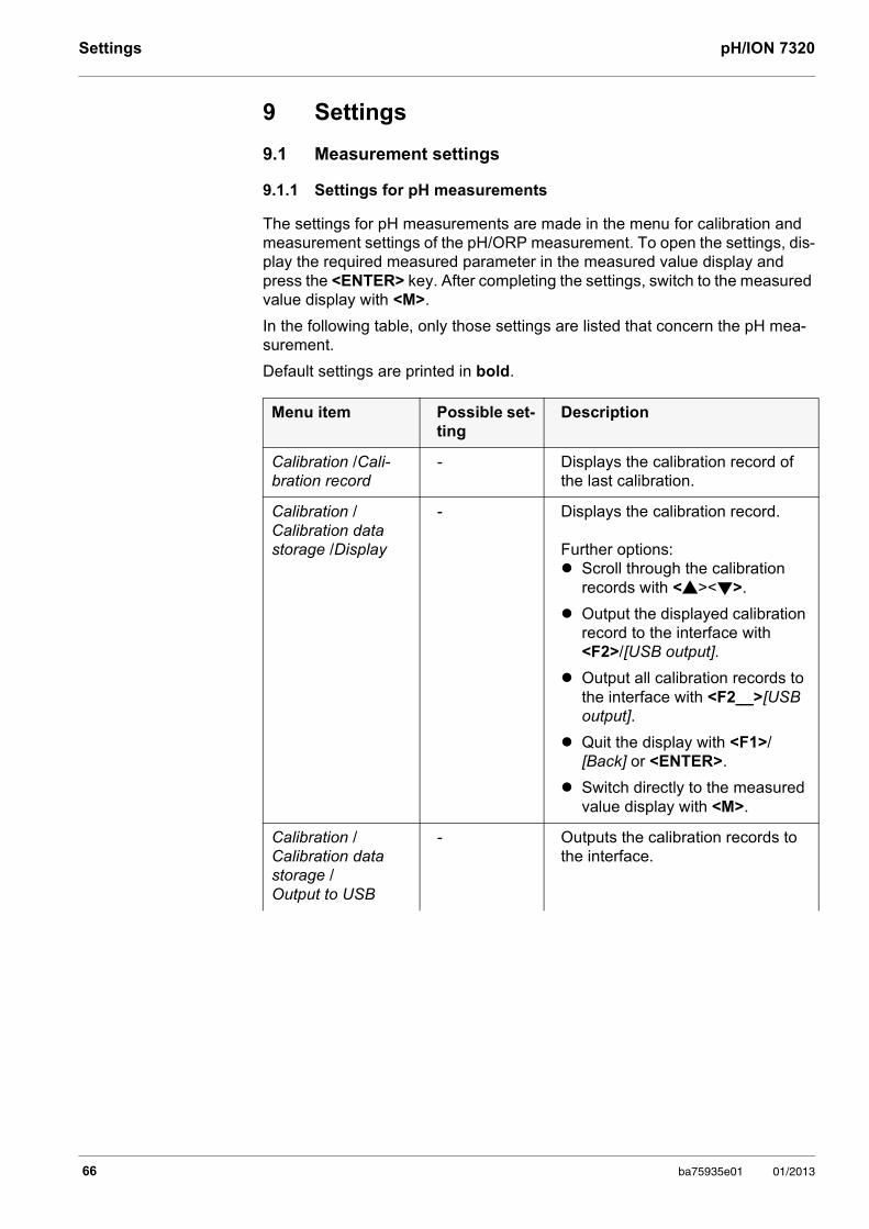
Settings pH/ION 7320
9 Settings
9.1 Measurement settings
9.1.1 Settings for pH measurements
The settings for pH measurements are made in the menu for calibration and measurement settings of the pH/ORP measurement. To open the settings, dis-play the required measured parameter in the measured value display and press the <ENTER> key. After completing the settings, switch to the measured value display with <M>.
In the following table, only those settings are listed that concern the pH mea-surement.
Default settings are printed in bold.
Menu item Possible set-ting
Description
Calibration /Cali-bration record
- Displays the calibration record of the last calibration.
Calibration / Calibration data storage /Display
- Displays the calibration record.
Further options: Scroll through the calibration
records with <><>.
Output the displayed calibration record to the interface with <F2>/[USB output].
Output all calibration records to the interface with <F2__>[USB output].
Quit the display with <F1>/[Back] or <ENTER>.
Switch directly to the measured value display with <M>.
Calibration / Calibration data storage / Output to USB
- Outputs the calibration records to the interface.
66 ba75935e01 01/2013
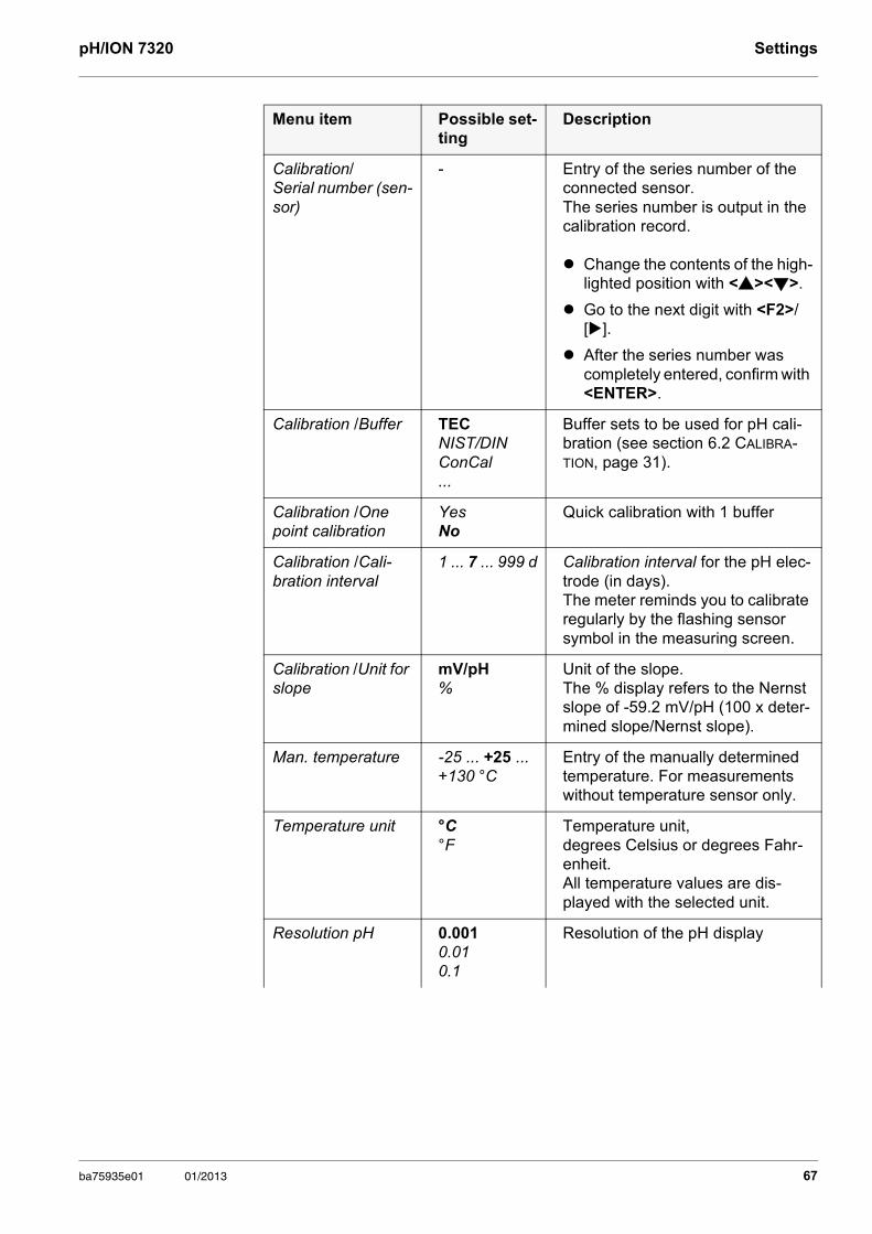
pH/ION 7320 Settings
Calibration/ Serial number (sen-sor)
- Entry of the series number of the connected sensor. The series number is output in the calibration record.
Change the contents of the high-lighted position with <><>.
Go to the next digit with <F2>/[].
After theseries number was completely entered, confirm with <ENTER>.
Calibration /Buffer TECNIST/DIN ConCal...
Buffer sets to be used for pH cali-bration (see section 6.2 CALIBRA-TION, page 31).
Calibration /One point calibration
YesNo
Quick calibration with 1 buffer
Calibration /Cali-bration interval
1 ... 7 ... 999 d Calibration interval for the pH elec-trode (in days).The meter reminds you to calibrate regularly by the flashing sensor symbol in the measuring screen.
Calibration /Unit for slope
mV/pH%
Unit of the slope.The % display refers to the Nernst slope of -59.2 mV/pH (100 x deter-mined slope/Nernst slope).
Man. temperature -25 ... +25 ... +130 °C
Entry of the manually determined temperature. For measurements without temperature sensor only.
Temperature unit °C °F
Temperature unit, degrees Celsius or degrees Fahr-enheit.All temperature values are dis-played with the selected unit.
Resolution pH 0.0010.010.1
Resolution of the pH display
Menu item Possible set-ting
Description
ba75935e01 01/2013 67
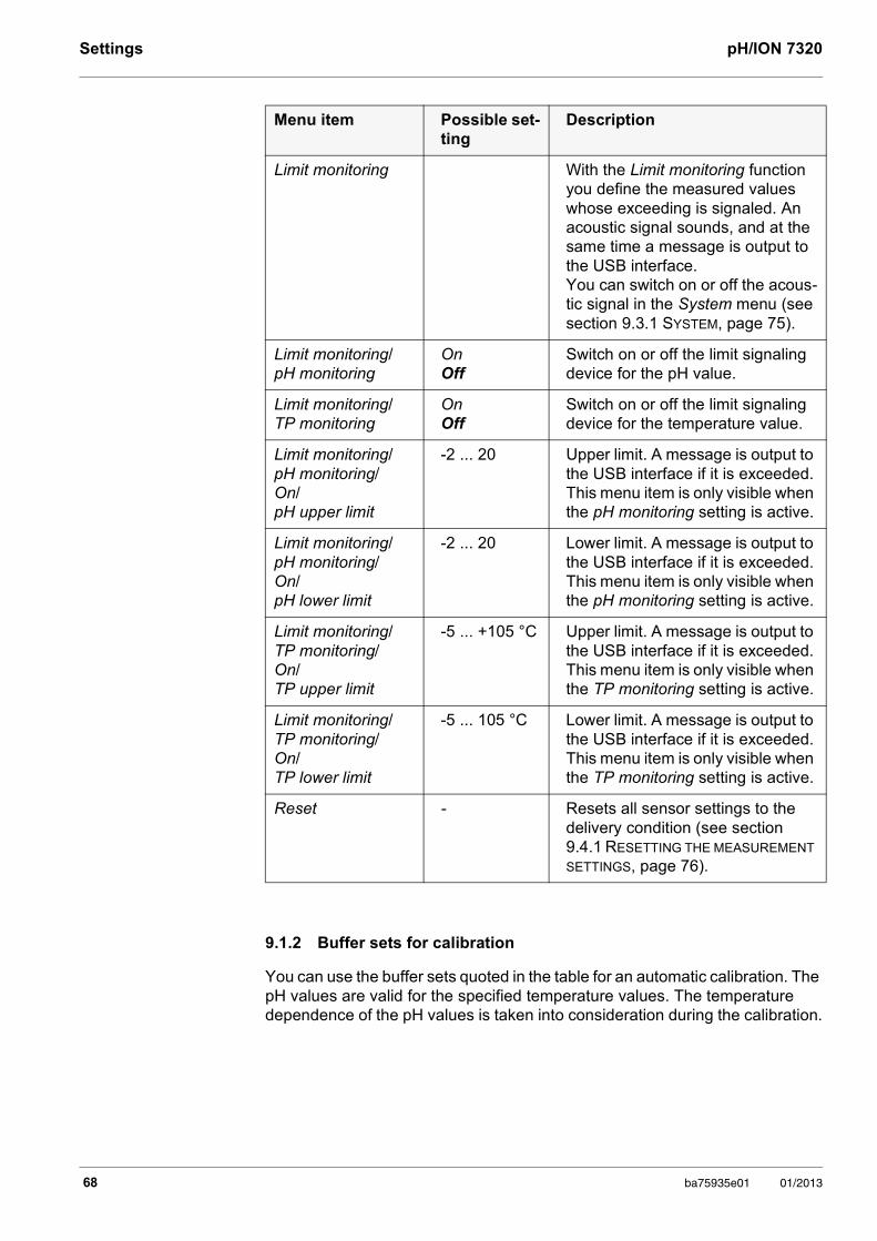
Settings pH/ION 7320
9.1.2 Buffer sets for calibration
You can use the buffer sets quoted in the table for an automatic calibration. The pH values are valid for the specified temperature values. The temperature dependence of the pH values is taken into consideration during the calibration.
Limit monitoring With the Limit monitoring function you define the measured values whose exceeding is signaled. An acoustic signal sounds, and at the same time a message is output to the USB interface.You can switch on or off the acous-tic signal in the System menu (see section 9.3.1 SYSTEM, page 75).
Limit monitoring/ pH monitoring
OnOff
Switch on or off the limit signaling device for the pH value.
Limit monitoring/ TP monitoring
OnOff
Switch on or off the limit signaling device for the temperature value.
Limit monitoring/pH monitoring/On/pH upper limit
-2 ... 20 Upper limit. A message is output to the USB interface if it is exceeded. This menu item is only visible when the pH monitoring setting is active.
Limit monitoring/pH monitoring/On/pH lower limit
-2 ... 20 Lower limit. A message is output to the USB interface if it is exceeded. This menu item is only visible when the pH monitoring setting is active.
Limit monitoring/TP monitoring/On/TP upper limit
-5 ... +105 °C Upper limit. A message is output to the USB interface if it is exceeded. This menu item is only visible when the TP monitoring setting is active.
Limit monitoring/TP monitoring/On/TP lower limit
-5 ... 105 °C Lower limit. A message is output to the USB interface if it is exceeded. This menu item is only visible when the TP monitoring setting is active.
Reset - Resets all sensor settings to the delivery condition (see section 9.4.1 RESETTING THE MEASUREMENT SETTINGS, page 76).
Menu item Possible set-ting
Description
68 ba75935e01 01/2013
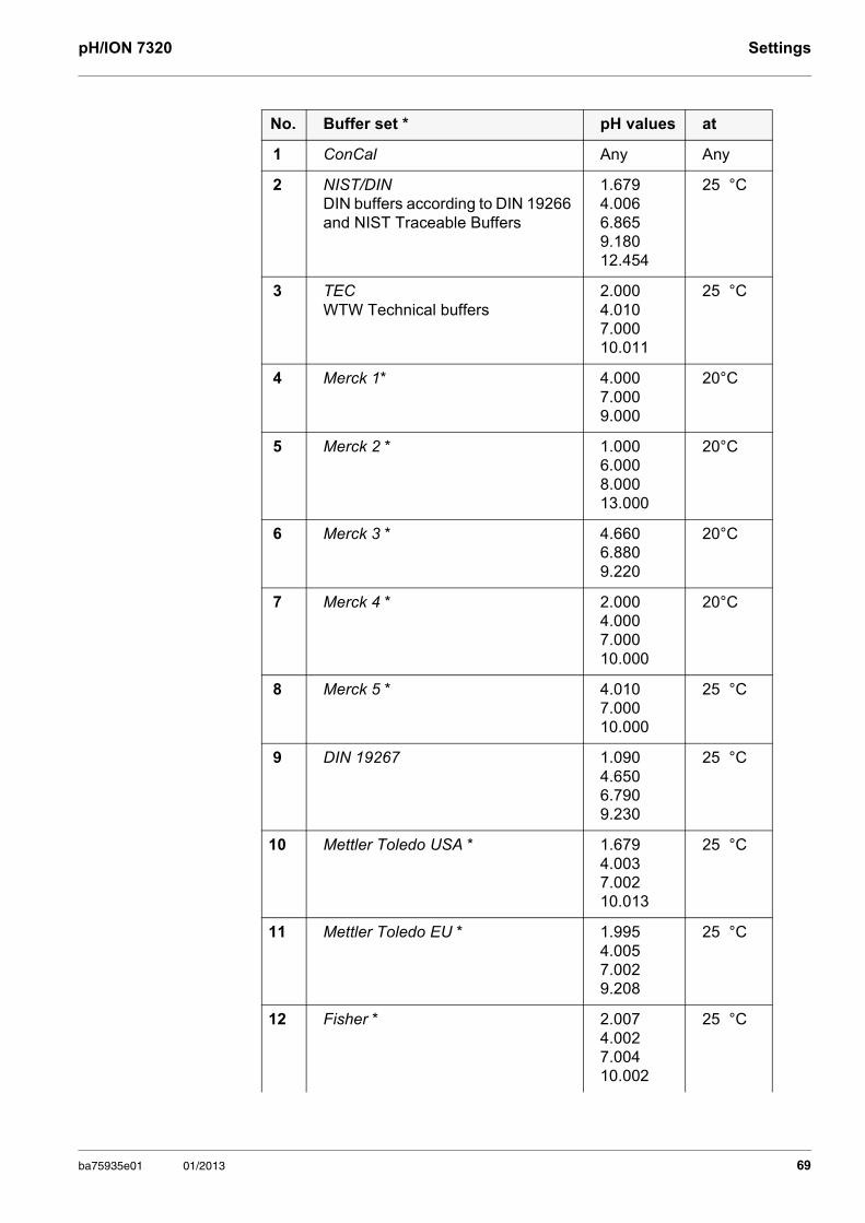
pH/ION 7320 Settings
No. Buffer set * pH values at
1 ConCal Any Any
2 NIST/DINDIN buffers according to DIN 19266 and NIST Traceable Buffers
1.6794.0066.8659.18012.454
25 °C
3 TECWTW Technical buffers
2.0004.0107.00010.011
25 °C
4 Merck 1* 4.0007.0009.000
20°C
5 Merck 2 * 1.0006.0008.00013.000
20°C
6 Merck 3 * 4.6606.8809.220
20°C
7 Merck 4 * 2.0004.0007.00010.000
20°C
8 Merck 5 * 4.0107.00010.000
25 °C
9 DIN 19267 1.0904.6506.7909.230
25 °C
10 Mettler Toledo USA * 1.6794.0037.00210.013
25 °C
11 Mettler Toledo EU * 1.9954.0057.0029.208
25 °C
12 Fisher * 2.0074.0027.00410.002
25 °C
ba75935e01 01/2013 69
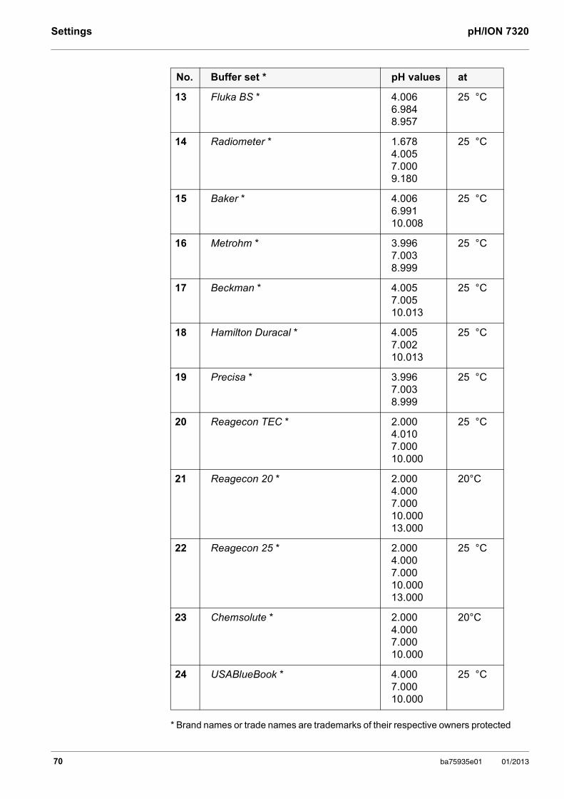
Settings pH/ION 7320
* Brand names or trade names are trademarks of their respective owners protected
13 Fluka BS * 4.0066.9848.957
25 °C
14 Radiometer * 1.6784.0057.0009.180
25 °C
15 Baker * 4.0066.99110.008
25 °C
16 Metrohm * 3.9967.0038.999
25 °C
17 Beckman * 4.0057.00510.013
25 °C
18 Hamilton Duracal * 4.0057.00210.013
25 °C
19 Precisa * 3.9967.0038.999
25 °C
20 Reagecon TEC * 2.0004.0107.00010.000
25 °C
21 Reagecon 20 * 2.0004.0007.00010.00013.000
20°C
22 Reagecon 25 * 2.0004.0007.00010.00013.000
25 °C
23 Chemsolute * 2.0004.0007.00010.000
20°C
24 USABlueBook * 4.0007.00010.000
25 °C
No. Buffer set * pH values at
70 ba75935e01 01/2013
pH/ION 7320 Settings
by law.
9.1.3 Calibration interval
The calibration evaluation is displayed as a sensor symbol.
The sensor symbol flashes after the adjusted calibration interval has expired. It is still possible to measure.
Setting the calibration interval
The calibration interval is set to 7 days in the factory. You can change the interval (1 ... 999 days):
The buffers are selected in the menu, pH / <ENTER> / Calibration / Buffer (see 9.1.1 SETTINGS FOR PH MEASUREMENTS, PAGE 66).
To ensure the high measuring accuracy of the measuring system, calibrate after the calibration interval has expired.
1. Open the menu for measurement settings with <ENTER>.
2. In the Calibration / Calibration interval menu, set the calibration interval with <><>.
3. Confirm the setting with <ENTER>.
4. Quit the menu with <M>.
ba75935e01 01/2013 71
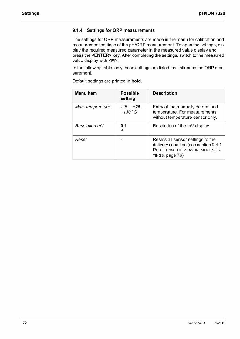
Settings pH/ION 7320
9.1.4 Settings for ORP measurements
The settings for ORP measurements are made in the menu for calibration and measurement settings of the pH/ORP measurement. To open the settings, dis-play the required measured parameter in the measured value display and press the <ENTER> key. After completing the settings, switch to the measured value display with <M>.
In the following table, only those settings are listed that influence the ORP mea-surement.
Default settings are printed in bold.
Menu item Possible setting
Description
Man. temperature -25 ... +25 ... +130 °C
Entry of the manually determined temperature. For measurements without temperature sensor only.
Resolution mV 0.11
Resolution of the mV display
Reset - Resets all sensor settings to the delivery condition (see section 9.4.1 RESETTING THE MEASUREMENT SET-TINGS, page 76).
72 ba75935e01 01/2013
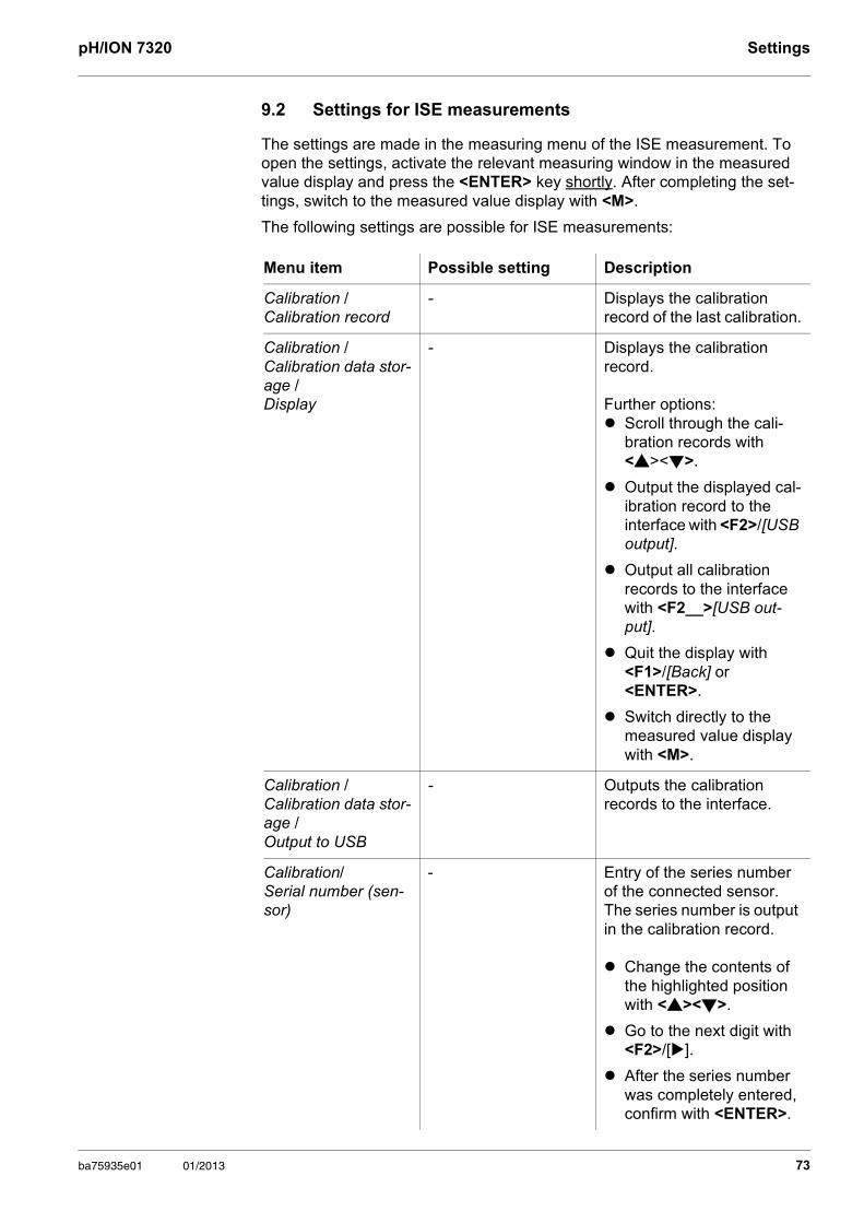
pH/ION 7320 Settings
9.2 Settings for ISE measurements
The settings are made in the measuring menu of the ISE measurement. To open the settings, activate the relevant measuring window in the measured value display and press the <ENTER> key shortly. After completing the set-tings, switch to the measured value display with <M>.
The following settings are possible for ISE measurements:
Menu item Possible setting Description
Calibration / Calibration record
- Displays the calibration record of the last calibration.
Calibration / Calibration data stor-age /Display
- Displays the calibration record.
Further options: Scroll through the cali-
bration records with <><>.
Output the displayed cal-ibration record to the interface with <F2>/[USB output].
Output all calibration records to the interface with <F2__>[USB out-put].
Quit the display with <F1>/[Back] or <ENTER>.
Switch directly to the measured value display with <M>.
Calibration / Calibration data stor-age /Output to USB
- Outputs the calibration records to the interface.
Calibration/ Serial number (sen-sor)
- Entry of the series number of the connected sensor. The series number is output in the calibration record.
Change the contents of the highlighted position with <><>.
Go to the next digit with <F2>/[].
After theseries number was completely entered, confirm with <ENTER>.
ba75935e01 01/2013 73
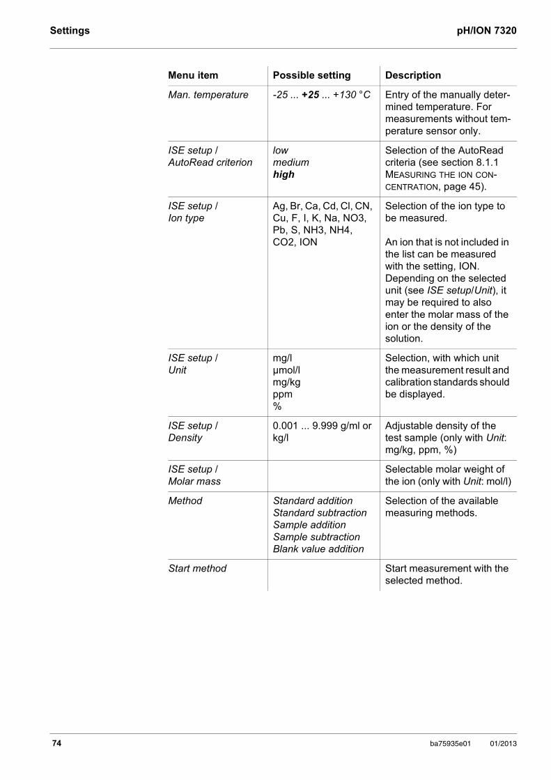
Settings pH/ION 7320
Man. temperature -25 ... +25 ... +130 °C Entry of the manually deter-mined temperature. For measurements without tem-perature sensor only.
ISE setup /AutoRead criterion
lowmediumhigh
Selection of the AutoRead criteria (see section 8.1.1 MEASURING THE ION CON-CENTRATION, page 45).
ISE setup /Ion type
Ag, Br, Ca, Cd, Cl, CN, Cu, F, I, K, Na, NO3, Pb, S, NH3, NH4, CO2, ION
Selection of the ion type to be measured.
An ion that is not included in the list can be measured with the setting, ION. Depending on the selected unit (see ISE setup/Unit), it may be required to also enter the molar mass of the ion or the density of the solution.
ISE setup /Unit
mg/lµmol/lmg/kgppm%
Selection, with which unit the measurement result and calibration standards should be displayed.
ISE setup /Density
0.001 ... 9.999 g/ml or kg/l
Adjustable density of the test sample (only with Unit: mg/kg, ppm, %)
ISE setup /Molar mass
Selectable molar weight of the ion (only with Unit: mol/l)
Method Standard additionStandard subtractionSample additionSample subtractionBlank value addition
Selection of the available measuring methods.
Start method Start measurement with the selected method.
Menu item Possible setting Description
74 ba75935e01 01/2013
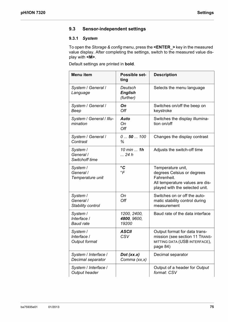
pH/ION 7320 Settings
9.3 Sensor-independent settings
9.3.1 System
To open the Storage & config menu, press the <ENTER_> key in the measured value display. After completing the settings, switch to the measured value dis-play with <M>.
Default settings are printed in bold.
Menu item Possible set-ting
Description
System / General / Language
DeutschEnglish(further)
Selects the menu language
System / General / Beep
OnOff
Switches on/off the beep on keystroke
System / General / Illu-mination
AutoOnOff
Switches the display illumina-tion on/off
System / General / Contrast
0 ... 50 ... 100 %
Changes the display contrast
System / General / Switchoff time
10 min ... 1h ... 24 h
Adjusts the switch-off time
System / General / Temperature unit
°C °F
Temperature unit, degrees Celsius or degrees Fahrenheit.All temperature values are dis-played with the selected unit.
System / General / Stability control
On Off
Switches on or off the auto-matic stability control during measurement
System / Interface / Baud rate
1200, 2400, 4800, 9600, 19200
Baud rate of the data interface
System / Interface / Output format
ASCIICSV
Output format for data trans-mission (see section 11 TRANS-MITTING DATA (USB INTERFACE), page 84)
System / Interface / Decimal separator
Dot (xx.x)Comma (xx,x)
Decimal separator
System / Interface / Output header
Output of a header for Output format: CSV
ba75935e01 01/2013 75
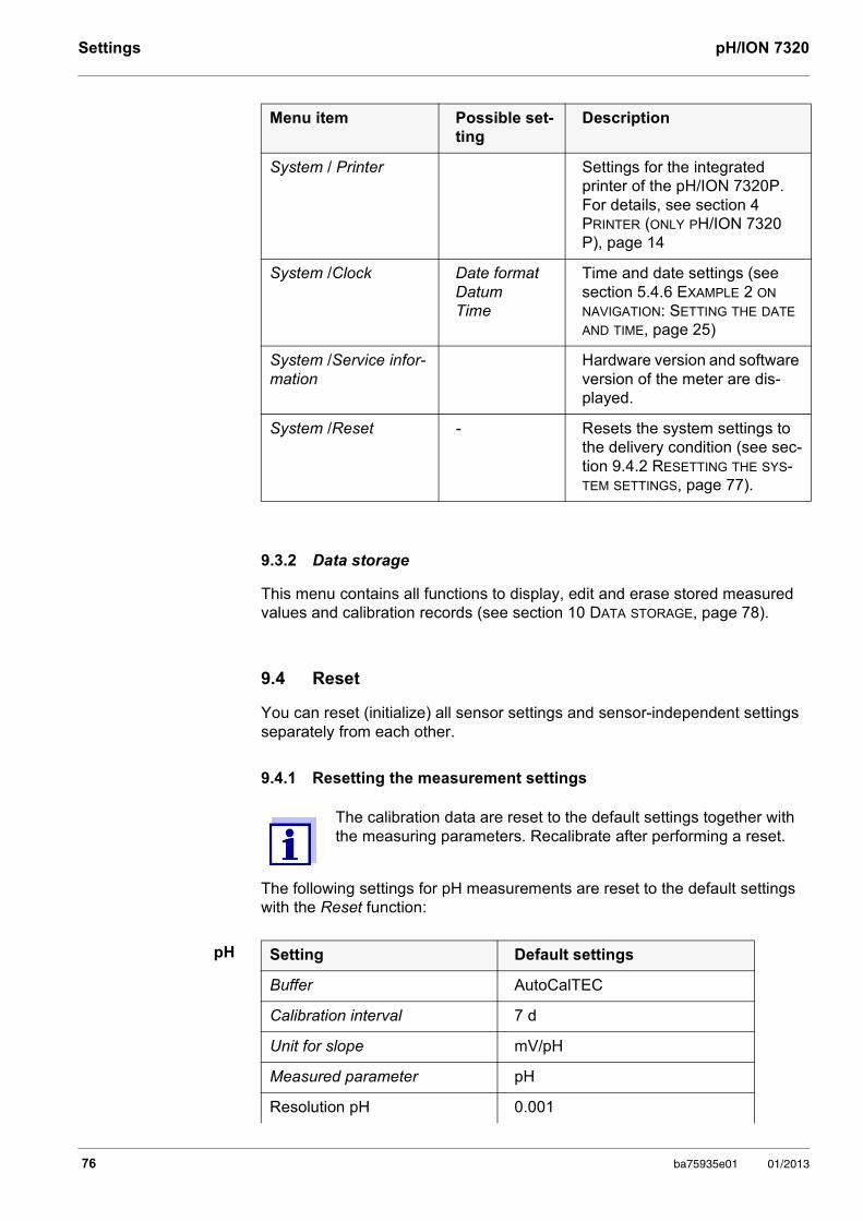
Settings pH/ION 7320
9.3.2 Data storage
This menu contains all functions to display, edit and erase stored measured values and calibration records (see section 10 DATA STORAGE, page 78).
9.4 Reset
You can reset (initialize) all sensor settings and sensor-independent settings separately from each other.
9.4.1 Resetting the measurement settings
The following settings for pH measurements are reset to the default settings with the Reset function:
pH
System / Printer Settings for the integrated printer of the pH/ION 7320P. For details, see section 4 PRINTER (ONLY PH/ION 7320 P), page 14
System /Clock Date formatDatumTime
Time and date settings (see section 5.4.6 EXAMPLE 2 ON NAVIGATION: SETTING THE DATE AND TIME, page 25)
System /Service infor-mation
Hardware version and software version of the meter are dis-played.
System /Reset - Resets the system settings to the delivery condition (see sec-tion 9.4.2 RESETTING THE SYS-TEM SETTINGS, page 77).
The calibration data are reset to the default settings together with the measuring parameters. Recalibrate after performing a reset.
Menu item Possible set-ting
Description
Setting Default settings
Buffer AutoCalTEC
Calibration interval 7 d
Unit for slope mV/pH
Measured parameter pH
Resolution pH 0.001
76 ba75935e01 01/2013
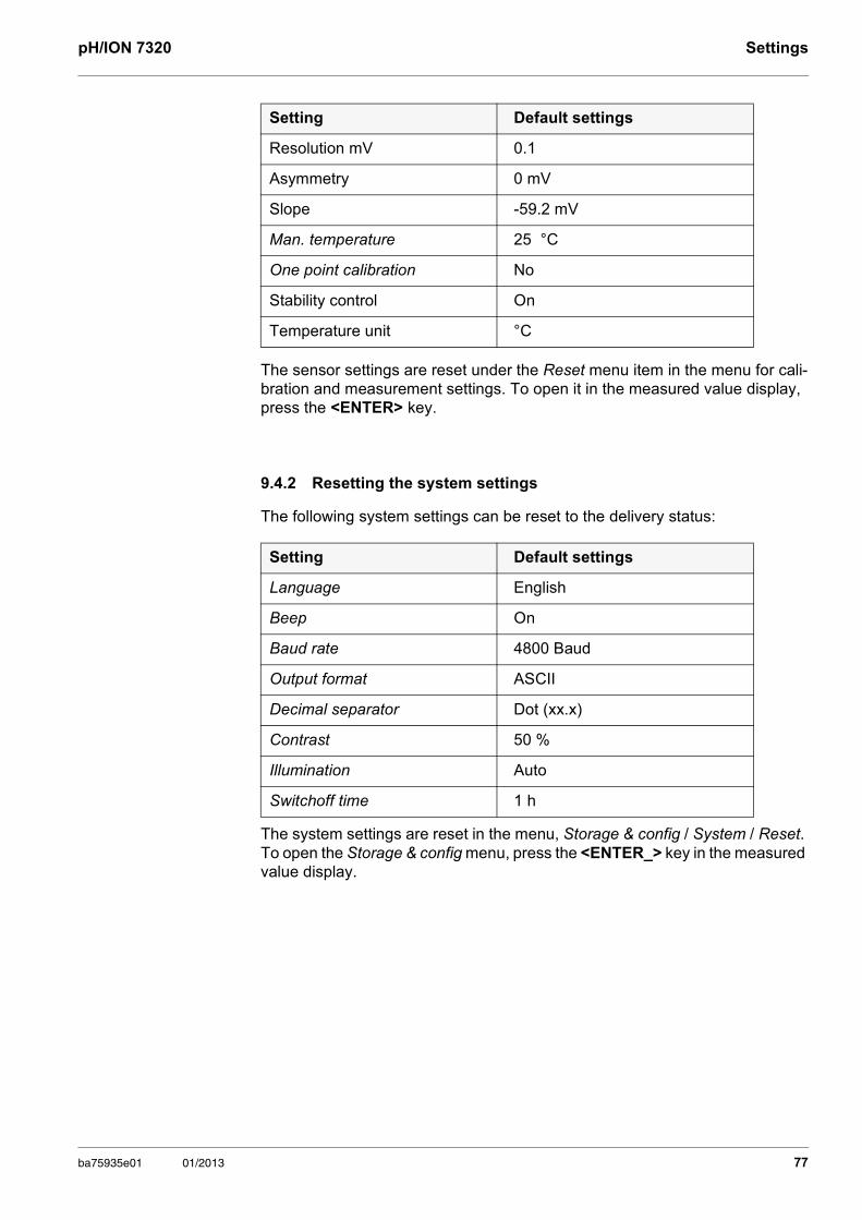
pH/ION 7320 Settings
The sensor settings are reset under the Reset menu item in the menu for cali-bration and measurement settings. To open it in the measured value display, press the <ENTER> key.
9.4.2 Resetting the system settings
The following system settings can be reset to the delivery status:
The system settings are reset in the menu, Storage & config / System / Reset. To open the Storage & config menu, press the <ENTER_> key in the measured value display.
Resolution mV 0.1
Asymmetry 0 mV
Slope -59.2 mV
Man. temperature 25 °C
One point calibration No
Stability control On
Temperature unit °C
Setting Default settings
Language English
Beep On
Baud rate 4800 Baud
Output format ASCII
Decimal separator Dot (xx.x)
Contrast 50 %
Illumination Auto
Switchoff time 1 h
Setting Default settings
ba75935e01 01/2013 77
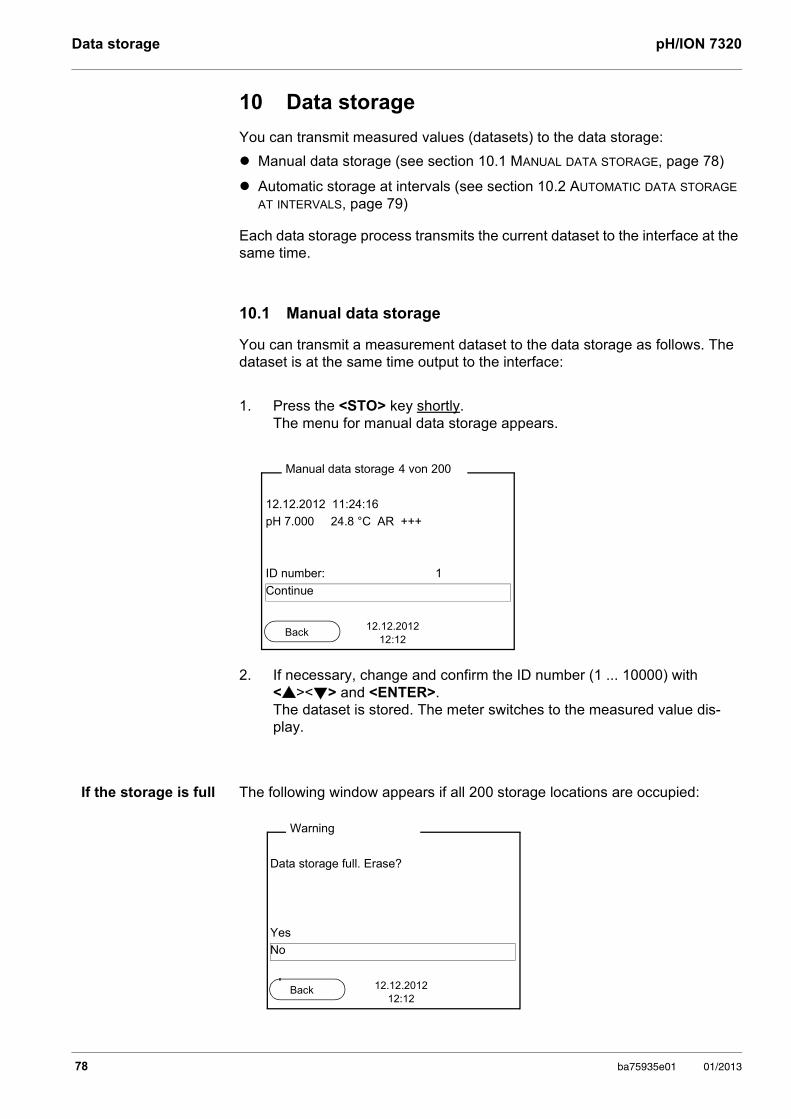
Data storage pH/ION 7320
10 Data storage
You can transmit measured values (datasets) to the data storage:
Manual data storage (see section 10.1 MANUAL DATA STORAGE, page 78)
Automatic storage at intervals (see section 10.2 AUTOMATIC DATA STORAGE AT INTERVALS, page 79)
Each data storage process transmits the current dataset to the interface at the same time.
10.1 Manual data storage
You can transmit a measurement dataset to the data storage as follows. The dataset is at the same time output to the interface:
If the storage is full The following window appears if all 200 storage locations are occupied:
1. Press the <STO> key shortly. The menu for manual data storage appears.
2. If necessary, change and confirm the ID number (1 ... 10000) with <><> and <ENTER>.The dataset is stored. The meter switches to the measured value dis-play.
12.12.2012 11:24:16
pH 7.000 24.8 °C AR +++
ID number: 1
Continue
Manual data storage 4 von 200
12.12.201212:12
Back
Data storage full. Erase?
Yes
No
Warning
12.12.201212:12
Back
78 ba75935e01 01/2013
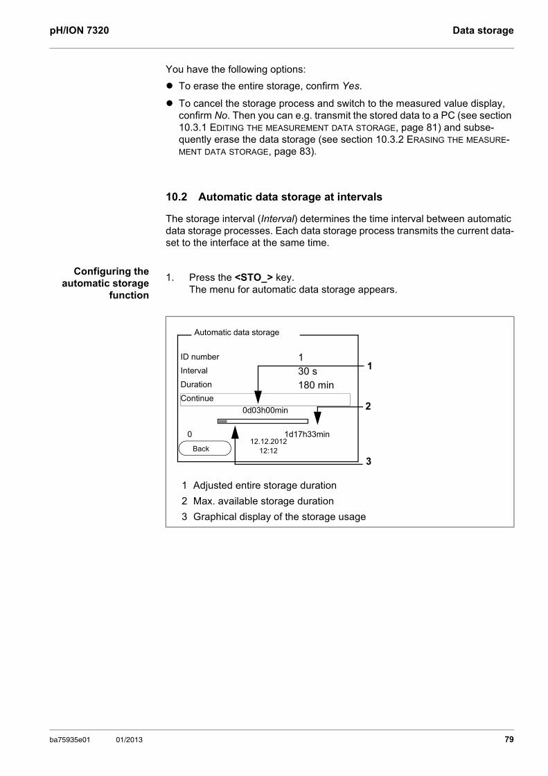
pH/ION 7320 Data storage
You have the following options:
To erase the entire storage, confirm Yes.
To cancel the storage process and switch to the measured value display, confirm No. Then you can e.g. transmit the stored data to a PC (see section 10.3.1 EDITING THE MEASUREMENT DATA STORAGE, page 81) and subse-quently erase the data storage (see section 10.3.2 ERASING THE MEASURE-MENT DATA STORAGE, page 83).
10.2 Automatic data storage at intervals
The storage interval (Interval) determines the time interval between automatic data storage processes. Each data storage process transmits the current data-set to the interface at the same time.
Configuring the automatic storage
function
1. Press the <STO_> key.The menu for automatic data storage appears.
1 Adjusted entire storage duration
2 Max. available storage duration
3 Graphical display of the storage usage
1ID number 1Interval 30 sDuration 180 minContinue
0d03h00min
0 1d17h33min
Automatic data storage
12.12.201212:12
2
3Back
ba75935e01 01/2013 79
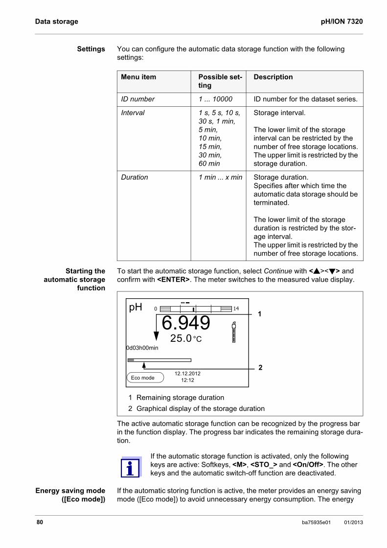
Data storage pH/ION 7320
Settings You can configure the automatic data storage function with the following settings:
Starting the automatic storage
function
To start the automatic storage function, select Continue with <><> and confirm with <ENTER>. The meter switches to the measured value display.
The active automatic storage function can be recognized by the progress bar in the function display. The progress bar indicates the remaining storage dura-tion.
Energy saving mode ([Eco mode])
If the automatic storing function is active, the meter provides an energy saving mode ([Eco mode]) to avoid unnecessary energy consumption. The energy
Menu item Possible set-ting
Description
ID number 1 ... 10000 ID number for the dataset series.
Interval 1 s, 5 s, 10 s, 30 s, 1 min, 5 min, 10 min, 15 min, 30 min, 60 min
Storage interval.
The lower limit of the storage interval can be restricted by the number of free storage locations.The upper limit is restricted by the storage duration.
Duration 1 min ... x min Storage duration.Specifies after which time the automatic data storage should be terminated.
The lower limit of the storage duration is restricted by the stor-age interval.The upper limit is restricted by the number of free storage locations.
1 Remaining storage duration
2 Graphical display of the storage duration
If the automatic storage function is activated, only the following keys are active: Softkeys, <M>, <STO_> and <On/Off>. The other keys and the automatic switch-off function are deactivated.
1
2
pH
6.94925.0 °C
0d03h00min
12.12.201212:12
0 14
Eco mode
80 ba75935e01 01/2013
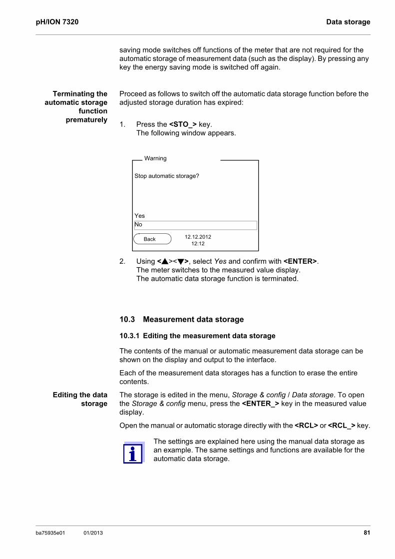
pH/ION 7320 Data storage
saving mode switches off functions of the meter that are not required for the automatic storage of measurement data (such as the display). By pressing any key the energy saving mode is switched off again.
Terminating the automatic storage
function prematurely
Proceed as follows to switch off the automatic data storage function before the adjusted storage duration has expired:
10.3 Measurement data storage
10.3.1 Editing the measurement data storage
The contents of the manual or automatic measurement data storage can be shown on the display and output to the interface.
Each of the measurement data storages has a function to erase the entire contents.
Editing the data storage
The storage is edited in the menu, Storage & config / Data storage. To open the Storage & config menu, press the <ENTER_> key in the measured value display.
Open the manual or automatic storage directly with the <RCL> or <RCL_> key.
1. Press the <STO_> key.The following window appears.
2. Using <><>, select Yes and confirm with <ENTER>.The meter switches to the measured value display.The automatic data storage function is terminated.
Stop automatic storage?
Yes
No
Warning
12.12.201212:12
Back
The settings are explained here using the manual data storage as an example. The same settings and functions are available for the automatic data storage.
ba75935e01 01/2013 81
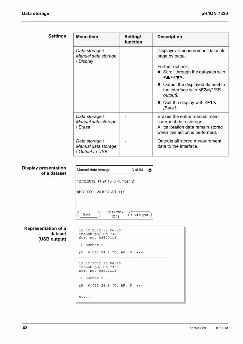
Data storage pH/ION 7320
Settings
Display presentation of a dataset
Representation of a dataset
(USB output)
Menu item Setting/function
Description
Data storage / Manual data storage / Display
- Displays all measurement datasets page by page.
Further options: Scroll through the datasets with
<><>.
Output the displayed dataset to the interface with <F2>/[USB output].
Quit the display with <F1>/[Back].
Data storage / Manual data storage / Erase
- Erases the entire manual mea-surement data storage.All calibration data remain stored when this action is performed.
Data storage / Manual data storage / Output to USB
- Outputs all stored measurement data to the interface.
Manual data storage 3 of 64
12.12.2012 11:24:16 ID number: 2
pH 7.000 24.8 °C AR +++
12.12.201212:12
Back USB output
12.12.2012 09:56:20inoLab pH/ION 7320 Ser. no. 08502113
ID number 2
pH 6.012 24.8 °C, AR, S: +++________________________________________
12.12.2012 10:56:20inoLab pH/ION 7320 Ser. no. 08502113
ID number 2
pH 6.012 24.8 °C, AR, S: +++________________________________________
etc...
82 ba75935e01 01/2013
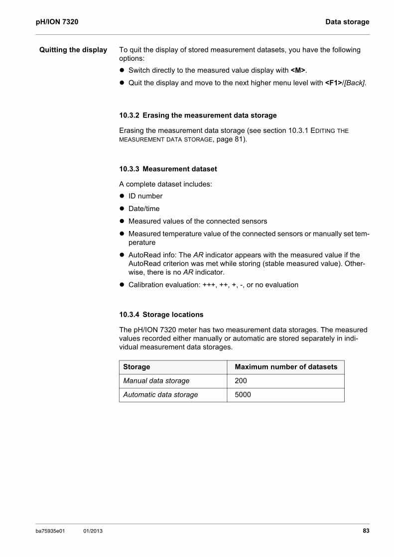
pH/ION 7320 Data storage
Quitting the display To quit the display of stored measurement datasets, you have the following options:
Switch directly to the measured value display with <M>.
Quit the display and move to the next higher menu level with <F1>/[Back].
10.3.2 Erasing the measurement data storage
Erasing the measurement data storage (see section 10.3.1 EDITING THE MEASUREMENT DATA STORAGE, page 81).
10.3.3 Measurement dataset
A complete dataset includes:
ID number
Date/time
Measured values of the connected sensors
Measured temperature value of the connected sensors or manually set tem-perature
AutoRead info: The AR indicator appears with the measured value if the AutoRead criterion was met while storing (stable measured value). Other-wise, there is no AR indicator.
Calibration evaluation: +++, ++, +, -, or no evaluation
10.3.4 Storage locations
The pH/ION 7320 meter has two measurement data storages. The measured values recorded either manually or automatic are stored separately in indi-vidual measurement data storages.
Storage Maximum number of datasets
Manual data storage 200
Automatic data storage 5000
ba75935e01 01/2013 83
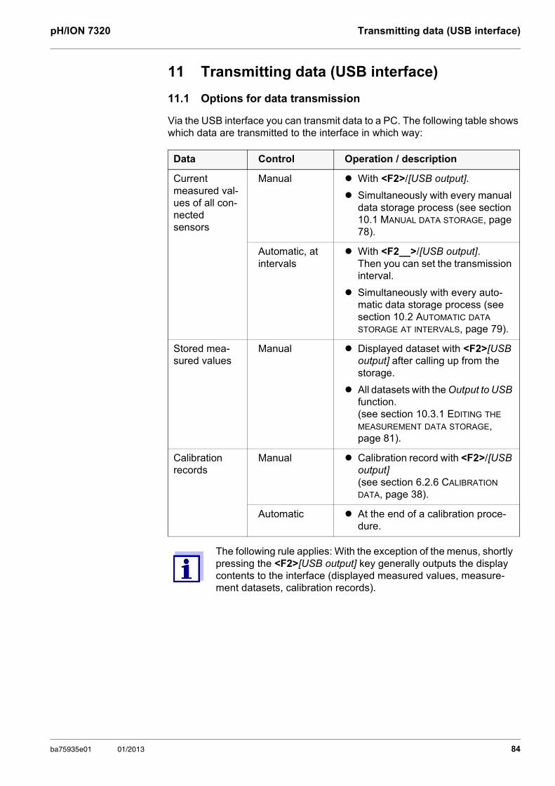
pH/ION 7320 Transmitting data (USB interface)
11 Transmitting data (USB interface)
11.1 Options for data transmission
Via the USB interface you can transmit data to a PC. The following table shows which data are transmitted to the interface in which way:
Data Control Operation / description
Current measured val-ues of all con-nected sensors
Manual With <F2>/[USB output].
Simultaneously with every manual data storage process (see section 10.1 MANUAL DATA STORAGE, page 78).
Automatic, at intervals
With <F2__>/[USB output]. Then you can set the transmission interval.
Simultaneously with every auto-matic data storage process (see section 10.2 AUTOMATIC DATA STORAGE AT INTERVALS, page 79).
Stored mea-sured values
Manual Displayed dataset with <F2>[USB output] after calling up from the storage.
All datasets with the Output to USB function. (see section 10.3.1 EDITING THE MEASUREMENT DATA STORAGE, page 81).
Calibration records
Manual Calibration record with <F2>/[USB output] (see section 6.2.6 CALIBRATION DATA, page 38).
Automatic At the end of a calibration proce-dure.
The following rule applies: With the exception of the menus, shortly pressing the <F2>[USB output] key generally outputs the display contents to the interface (displayed measured values, measure-ment datasets, calibration records).
ba75935e01 01/2013 84
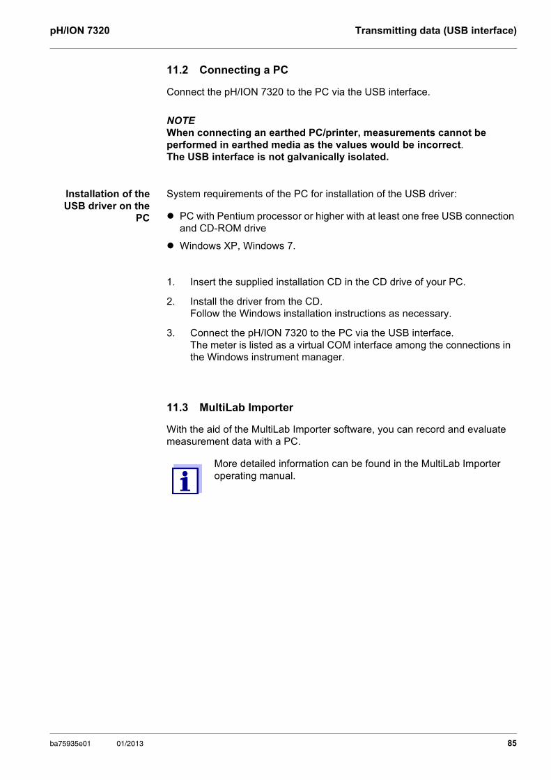
pH/ION 7320 Transmitting data (USB interface)
11.2 Connecting a PC
Connect the pH/ION 7320 to the PC via the USB interface.
NOTE When connecting an earthed PC/printer, measurements cannot be performed in earthed media as the values would be incorrect. The USB interface is not galvanically isolated.
Installation of the USB driver on the
PC
System requirements of the PC for installation of the USB driver:
PC with Pentium processor or higher with at least one free USB connection and CD-ROM drive
Windows XP, Windows 7.
11.3 MultiLab Importer
With the aid of the MultiLab Importer software, you can record and evaluate measurement data with a PC.
1. Insert the supplied installation CD in the CD drive of your PC.
2. Install the driver from the CD.Follow the Windows installation instructions as necessary.
3. Connect the pH/ION 7320 to the PC via the USB interface.The meter is listed as a virtual COM interface among the connections in the Windows instrument manager.
More detailed information can be found in the MultiLab Importer operating manual.
ba75935e01 01/2013 85
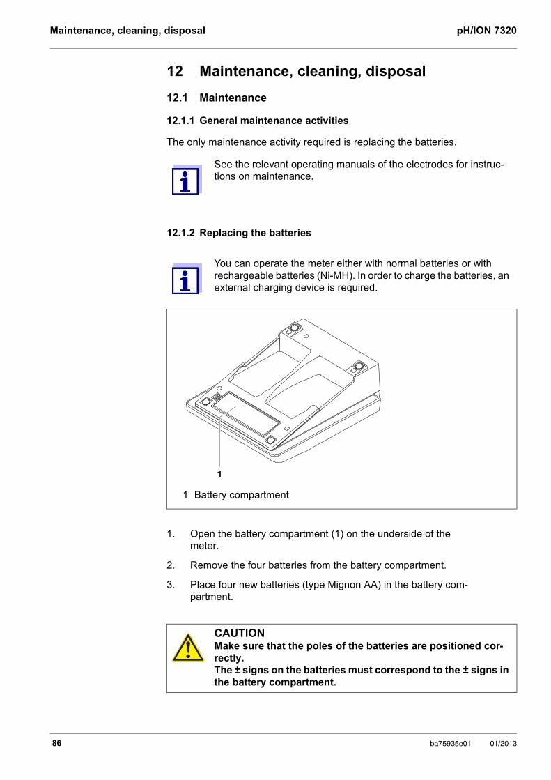
Maintenance, cleaning, disposal pH/ION 7320
12 Maintenance, cleaning, disposal
12.1 Maintenance
12.1.1 General maintenance activities
The only maintenance activity required is replacing the batteries.
12.1.2 Replacing the batteries
See the relevant operating manuals of the electrodes for instruc-tions on maintenance.
You can operate the meter either with normal batteries or with rechargeable batteries (Ni-MH). In order to charge the batteries, an external charging device is required.
1 Battery compartment
1. Open the battery compartment (1) on the underside of the meter.
2. Remove the four batteries from the battery compartment.
3. Place four new batteries (type Mignon AA) in the battery com-partment.
CAUTIONMake sure that the poles of the batteries are positioned cor-rectly. The ± signs on the batteries must correspond to the ± signs in the battery compartment.
1
86 ba75935e01 01/2013
pH/ION 7320 Maintenance, cleaning, disposal
12.2 Cleaning
Occasionally wipe the outside of the measuring instrument with a damp, lint-free cloth. Disinfect the housing with isopropanol as required.
12.3 Packing
This meter is sent out in a protective transport packing. We recommend: Keep the packing material. The original packing protects the meter against damage during transport.
12.4 Disposal
At the end of its operational lifetime, the meter must be returned to the disposal or return system statutory in your country. If you have any questions, please contact your supplier.
4. Close the battery compartment (1).
5. Set the date and time (see section 5.4.6 EXAMPLE 2 ON NAVIGATION: SETTING THE DATE AND TIME, page 25)
When the batteries are nearly discharged, the status indi-cator is displayed.
Dispose of used batteries according to the local regulations of your country.
End users within the European Union are obligated to return used batteries (even ecologically compatible ones) to a collection point set up for recycling purposes.
Batteries are marked with the crossed-out waste container symbol. Therefore, they may not be disposed with the domestic waste.
CAUTIONThe housing is made of synthetic material (ABS). Thus, avoid contact with acetone or similar detergents that contain sol-vents. Remove any splashes immediately.
ba75935e01 01/2013 87
What to do if... pH/ION 7320
13 What to do if...
13.1 pH/ORP
Error message OFL, UFL
The measured value is outside the measuring range.
Error message, Error
More information and instructions on cleaning and exchange of sensors are given in the documentation of your sensor.
Cause Remedy
pH electrode:
– Air bubble in front of the junction – Remove air bubble
– Air in the junction – Extract air or moisten junction
– Cable broken – Replace electrode
– Gel electrolyte dried out – Replace electrode
– Measured value outside the mea-suring range
– Use suitable electrode
Cause Remedy
pH electrode:
– The values determined for zero point and slope of the electrode are outside the allowed limits.
– Recalibrate
– Junction contaminated – Clean junction
– Electrode broken – Replace electrode
Buffer solutions:
– Wrong buffer solutions – Change calibration procedure
– Buffer solutions too old – Use only once. Note the shelf life
– Buffer solutions depleted – Change solutions
88 ba75935e01 01/2013
pH/ION 7320 What to do if...
No stable measured value
Obviously incorrect measured values
Cause Remedy
pH electrode:
– Junction contaminated – Clean the junction
– Membrane contaminated – Clean the membrane
Test sample:
– pH value not stable – Measure with air excluded if necessary
– Temperature not stable – Temper if necessary
Electrode + test sample:
– Conductivity too low – Use a suitable electrode
– Temperature too high – Use a suitable electrode
– Organic liquids – Use a suitable electrode
Cause Remedy
pH electrode:
– pH electrode unsuitable – Use a suitable electrode
– Temperature difference between buffer and test sample too great
– Adjust the temperature of buf-fer or sample solutions
– Measurement procedure not suit-able
– Follow a special procedure
ba75935e01 01/2013 89
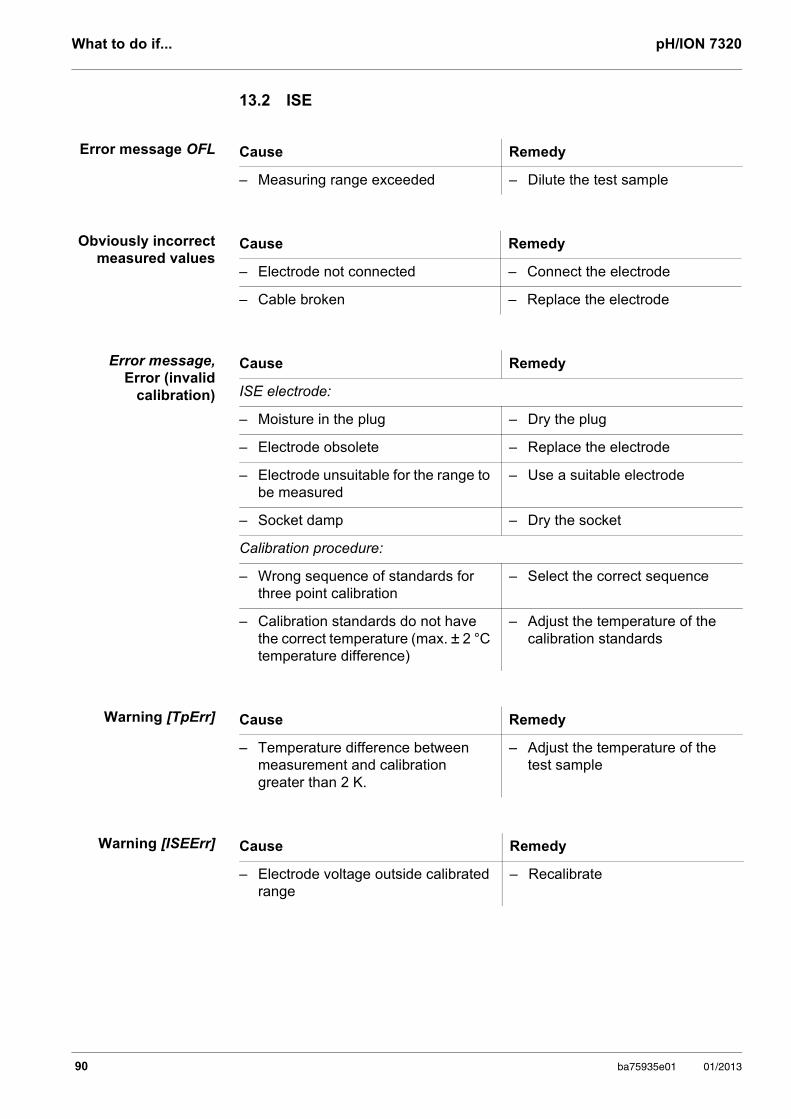
What to do if... pH/ION 7320
13.2 ISE
Error message OFL
Obviously incorrect measured values
Error message, Error (invalid
calibration)
Warning [TpErr]
Warning [ISEErr]
Cause Remedy
– Measuring range exceeded – Dilute the test sample
Cause Remedy
– Electrode not connected – Connect the electrode
– Cable broken – Replace the electrode
Cause Remedy
ISE electrode:
– Moisture in the plug – Dry the plug
– Electrode obsolete – Replace the electrode
– Electrode unsuitable for the range to be measured
– Use a suitable electrode
– Socket damp – Dry the socket
Calibration procedure:
– Wrong sequence of standards for three point calibration
– Select the correct sequence
– Calibration standards do not have the correct temperature (max. ± 2 °C temperature difference)
– Adjust the temperature of the calibration standards
Cause Remedy
– Temperature difference between measurement and calibration greater than 2 K.
– Adjust the temperature of the test sample
Cause Remedy
– Electrode voltage outside calibrated range
– Recalibrate
90 ba75935e01 01/2013
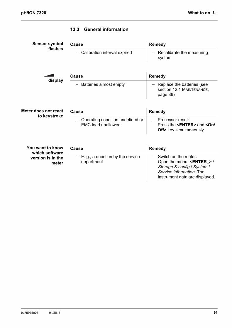
pH/ION 7320 What to do if...
13.3 General information
Sensor symbol flashes
display
Meter does not react to keystroke
You want to know which software
version is in the meter
Cause Remedy
– Calibration interval expired – Recalibrate the measuring system
Cause Remedy
– Batteries almost empty – Replace the batteries (see section 12.1 MAINTENANCE, page 86)
Cause Remedy
– Operating condition undefined or EMC load unallowed
– Processor reset: Press the <ENTER> and <On/Off> key simultaneously
Cause Remedy
– E. g., a question by the service department
– Switch on the meter. Open the menu, <ENTER_> / Storage & config / System / Service information. The instrument data are displayed.
ba75935e01 01/2013 91
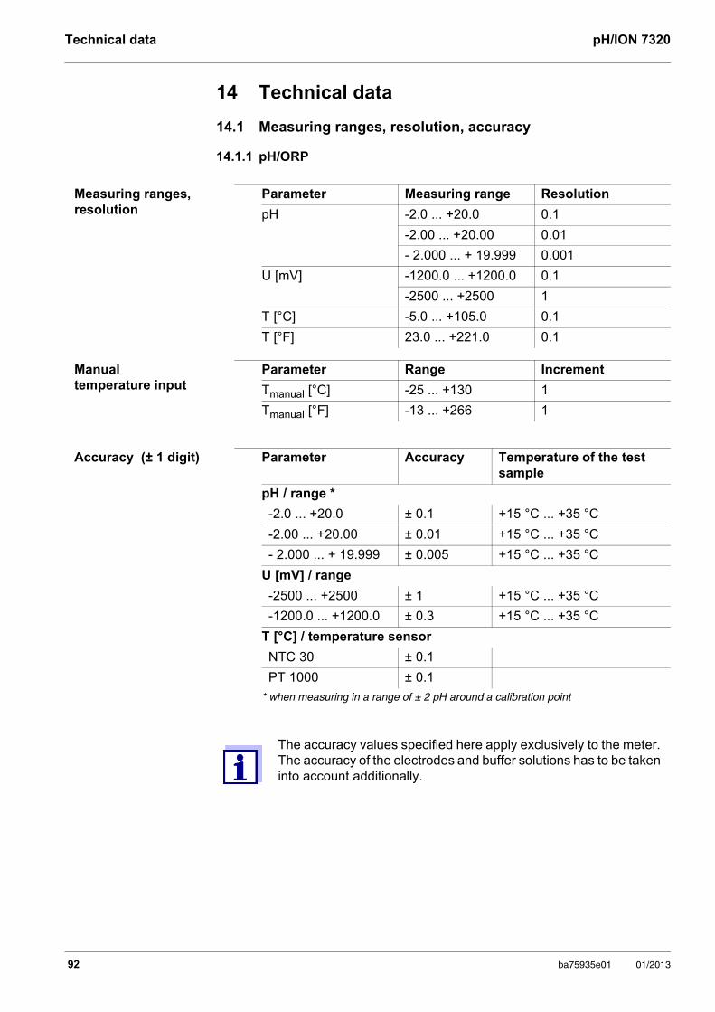
Technical data pH/ION 7320
14 Technical data
14.1 Measuring ranges, resolution, accuracy
14.1.1 pH/ORP
Measuring ranges, resolution
Parameter Measuring range Resolution
pH -2.0 ... +20.0 0.1
-2.00 ... +20.00 0.01
- 2.000 ... + 19.999 0.001
U [mV] -1200.0 ... +1200.0 0.1
-2500 ... +2500 1
T [°C] -5.0 ... +105.0 0.1
T [°F] 23.0 ... +221.0 0.1
Manual temperature input
Parameter Range Increment
Tmanual [°C] -25 ... +130 1
Tmanual [°F] -13 ... +266 1
Accuracy (± 1 digit) Parameter Accuracy Temperature of the test sample
pH / range *
-2.0 ... +20.0 ± 0.1 +15 °C ... +35 °C
-2.00 ... +20.00 ± 0.01 +15 °C ... +35 °C
- 2.000 ... + 19.999 ± 0.005 +15 °C ... +35 °C
U [mV] / range
-2500 ... +2500 ± 1 +15 °C ... +35 °C
-1200.0 ... +1200.0 ± 0.3 +15 °C ... +35 °C
T [°C] / temperature sensor
NTC 30 ± 0.1
PT 1000 ± 0.1
* when measuring in a range of ± 2 pH around a calibration point
The accuracy values specified here apply exclusively to the meter. The accuracy of the electrodes and buffer solutions has to be taken into account additionally.
92 ba75935e01 01/2013
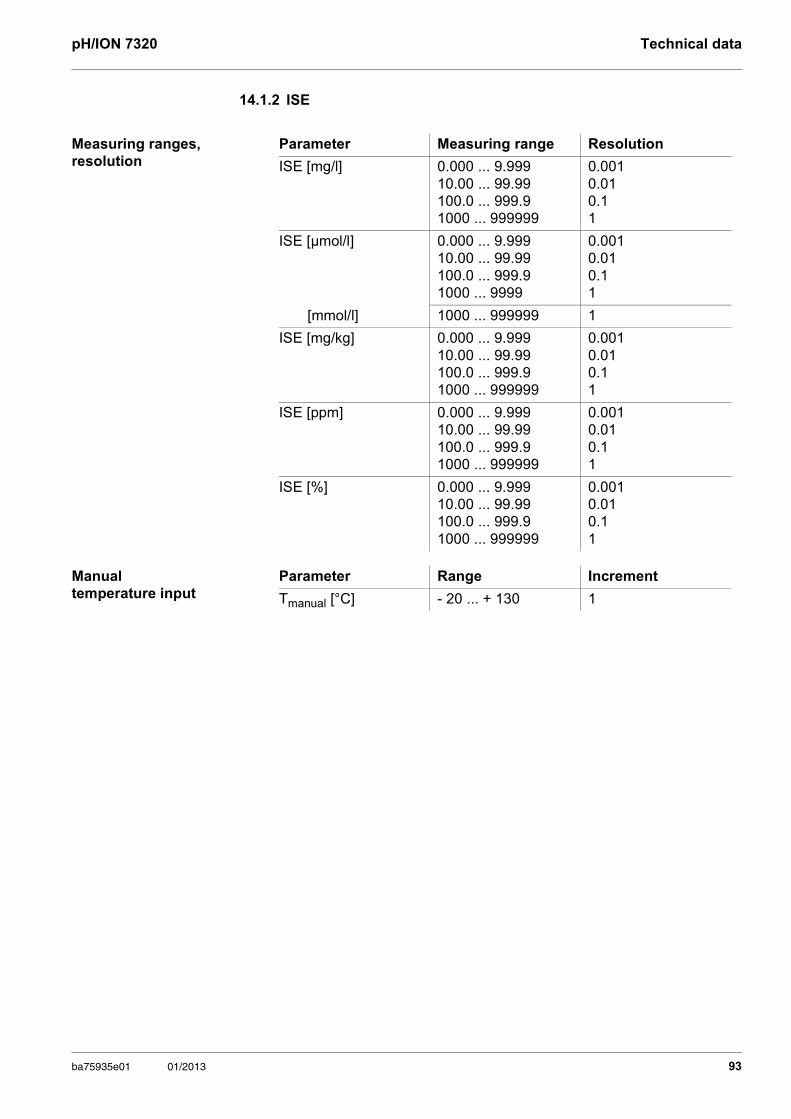
pH/ION 7320 Technical data
14.1.2 ISE
Measuring ranges, resolution
Parameter Measuring range Resolution
ISE [mg/l] 0.000 ... 9.99910.00 ... 99.99100.0 ... 999.91000 ... 999999
0.0010.010.11
ISE [µmol/l] 0.000 ... 9.99910.00 ... 99.99100.0 ... 999.91000 ... 9999
0.0010.010.11
[mmol/l] 1000 ... 999999 1
ISE [mg/kg] 0.000 ... 9.99910.00 ... 99.99100.0 ... 999.91000 ... 999999
0.0010.010.11
ISE [ppm] 0.000 ... 9.99910.00 ... 99.99100.0 ... 999.91000 ... 999999
0.0010.010.11
ISE [%] 0.000 ... 9.99910.00 ... 99.99100.0 ... 999.91000 ... 999999
0.0010.010.11
Manual temperature input
Parameter Range Increment
Tmanual [°C] - 20 ... + 130 1
ba75935e01 01/2013 93
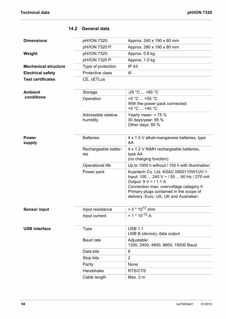
Technical data pH/ION 7320
14.2 General data
Dimensions pH/ION 7320: Approx. 240 x 190 x 80 mm
pH/ION 7320 P: Approx. 290 x 190 x 80 mm
Weight pH/ION 7320: Approx. 0.8 kg
pH/ION 7320 P: Approx. 1.0 kg
Mechanical structure Type of protection IP 43
Electrical safety Protective class III
Test certificates CE, cETLus
Ambient conditions
Storage -25 °C ... +65 °C
Operation +5 °C ... +55 °CWith the power pack connected: +5 °C ... +40 °C
Admissible relative humidity
Yearly mean: < 75 %30 days/year: 95 %Other days: 85 %
Power supply
Batteries 4 x 1.5 V alkali-manganese batteries, type AA
Rechargeable batter-ies
4 x 1.2 V NiMH rechargeable batteries, type AA (no charging function)
Operational life Up to 1000 h without / 150 h with illumination
Power pack Kuantech Co. Ltd. KSAC 0900110W1UV-1 Input: 100 ... 240 V ~ / 50 ... 60 Hz / 270 mA Output: 9 V = / 1.1 A Connection max. overvoltage category IIPrimary plugs contained in the scope of delivery: Euro, US, UK and Australian.
Sensor input Input resistance > 5 * 1012 ohm
Input current < 1 * 10-12 A
USB interface Type USB 1.1USB B (device), data output
Baud rate Adjustable: 1200, 2400, 4800, 9600, 19200 Baud
Data bits 8
Stop bits 2
Parity None
Handshake RTS/CTS
Cable length Max. 3 m
94 ba75935e01 01/2013
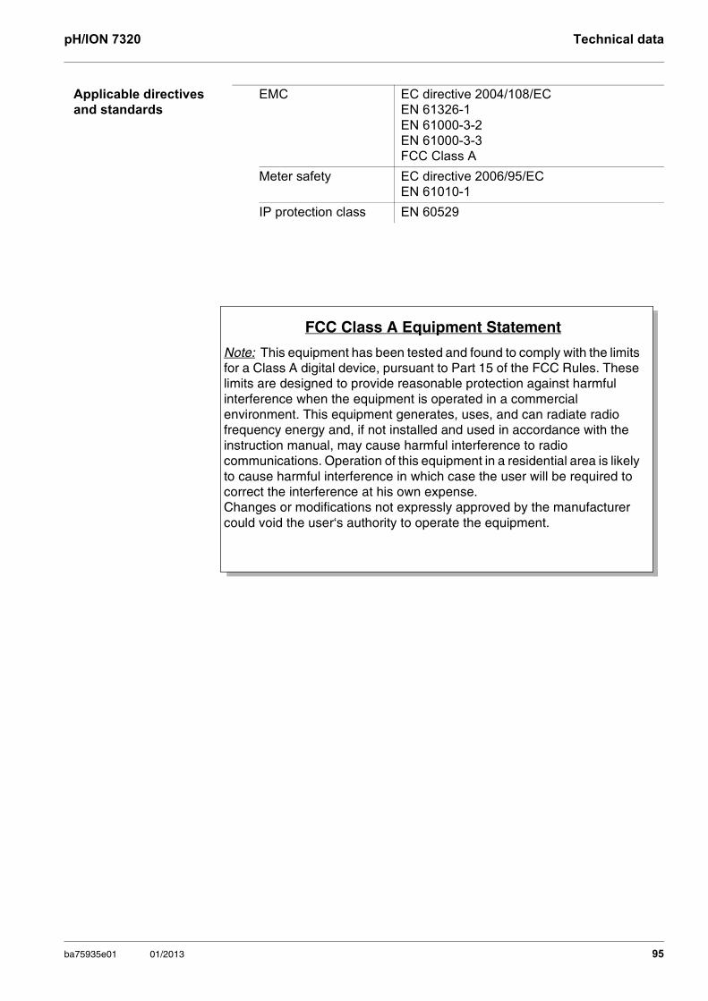
pH/ION 7320 Technical data
Applicable directives and standards
EMC EC directive 2004/108/ECEN 61326-1EN 61000-3-2EN 61000-3-3FCC Class A
Meter safety EC directive 2006/95/ECEN 61010-1
IP protection class EN 60529
FCC Class A Equipment Statement
Note: This equipment has been tested and found to comply with the limits for a Class A digital device, pursuant to Part 15 of the FCC Rules. These limits are designed to provide reasonable protection against harmful interference when the equipment is operated in a commercial environment. This equipment generates, uses, and can radiate radio frequency energy and, if not installed and used in accordance with the instruction manual, may cause harmful interference to radio communications. Operation of this equipment in a residential area is likely to cause harmful interference in which case the user will be required to correct the interference at his own expense.Changes or modifications not expressly approved by the manufacturer could void the user‘s authority to operate the equipment.
ba75935e01 01/2013 95
Firmware update pH/ION 7320
96 ba75935e01 01/2013
15 Firmware update
Available firmware updates are provided on the Internet. With the firmware update program and a PC you can update the firmware of the pH/ION 7320 to the newest version.
For the update you have to connect the meter to a PC.
For the update via the USB interface, the following is required:
a free USB interface (virtual COM port) on the PC
the driver for the USB interface (on the enclosed CD-ROM)
the USB cable (included in the scope of delivery of the pH/ION 7320).
After switching the meter off and on you can check whether the meter has taken over the new software version (see YOU WANT TO KNOW WHICH SOFTWARE VERSION IS IN THE METER, PAGE 91).
1. Install the downloaded firmware update on a PC.An update folder is created in the Windows start menu. If an update folder already exists for the meter (or meter type), the new data is displayed there.
2. In the windows start menu, open the update folder and start the firmware update program.
3. Using the USB interface cable, connect the pH/ION 7320 to a USB inter-face (virtual COM port) of the PC.
4. Switch on the pH/ION 7320.
5. In the firmware update program, start the update process with OK.
6. Follow the instructions of the firmware update program.During the programming process, a corresponding message and a progress bar (in %) are displayed. The programming process takes approx. three minutes. A terminatory message is displayed after a successful programming process. The firmware update is completed.
7. Disconnect the pH/ION 7320 from the PC. The pH/ION 7320 is ready for operation again.
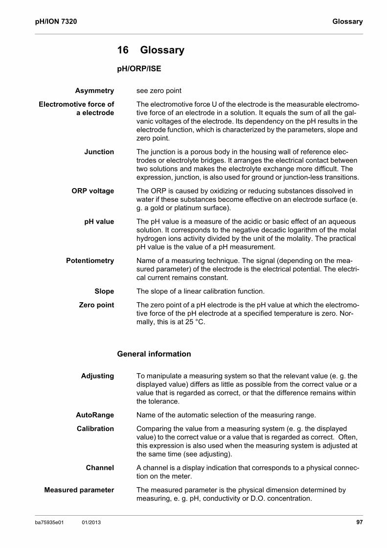
pH/ION 7320 Glossary
16 Glossary
pH/ORP/ISE
General information
Asymmetry see zero point
Electromotive force of a electrode
The electromotive force U of the electrode is the measurable electromo-tive force of an electrode in a solution. It equals the sum of all the gal-vanic voltages of the electrode. Its dependency on the pH results in the electrode function, which is characterized by the parameters, slope and zero point.
Junction The junction is a porous body in the housing wall of reference elec-trodes or electrolyte bridges. It arranges the electrical contact between two solutions and makes the electrolyte exchange more difficult. The expression, junction, is also used for ground or junction-less transitions.
ORP voltage The ORP is caused by oxidizing or reducing substances dissolved in water if these substances become effective on an electrode surface (e. g. a gold or platinum surface).
pH value The pH value is a measure of the acidic or basic effect of an aqueous solution. It corresponds to the negative decadic logarithm of the molal hydrogen ions activity divided by the unit of the molality. The practical pH value is the value of a pH measurement.
Potentiometry Name of a measuring technique. The signal (depending on the mea-sured parameter) of the electrode is the electrical potential. The electri-cal current remains constant.
Slope The slope of a linear calibration function.
Zero point The zero point of a pH electrode is the pH value at which the electromo-tive force of the pH electrode at a specified temperature is zero. Nor-mally, this is at 25 °C.
Adjusting To manipulate a measuring system so that the relevant value (e. g. the displayed value) differs as little as possible from the correct value or a value that is regarded as correct, or that the difference remains within the tolerance.
AutoRange Name of the automatic selection of the measuring range.
Calibration Comparing the value from a measuring system (e. g. the displayed value) to the correct value or a value that is regarded as correct. Often, this expression is also used when the measuring system is adjusted at the same time (see adjusting).
Channel A channel is a display indication that corresponds to a physical connec-tion on the meter.
Measured parameter The measured parameter is the physical dimension determined by measuring, e. g. pH, conductivity or D.O. concentration.
ba75935e01 01/2013 97
Glossary pH/ION 7320
Measured value The measured value is the special value of a measured parameter to be determined. It is given as a combination of the numerical value and unit (e. g. 3 m; 0.5 s; 5.2 A; 373.15 K).
Molality Molality is the quantity (in Mol) of a dissolved substance in 1000 g sol-vent.
Reset Restoring the original condition of all settings of a measuring system.
Resolution Smallest difference between two measured values that can be dis-played by a meter.
Stability control (Au-toRead )
Function to control the measured value stability.
Standard solution The standard solution is a solution where the measured value is known by definition. It is used to calibrate a measuring system.
Temperature function Name of a mathematical function expressing the temperature behavior of a test sample, a sensor or part of a sensor.
Test sample Designation of the test sample ready to be measured. Normally, a test sample is made by processing the original sample. The test sample and original sample are identical if the test sample was not processed.
98 ba75935e01 01/2013
pH/ION 7320 Index
17 Index
AAutomatic switch-off . . . . . . . . . . . . . . . . . . 20AutoRead
ORP . . . . . . . . . . . . . . . . . . . . . . . . 41, 43pH . . . . . . . . . . . . . . . . . . . . . . . . . 28, 45
BBattery compartment . . . . . . . . . . . . . . 12, 86Blank value addition . . . . . . . . . . . . . . . . . . 63
CCalibration
ISE . . . . . . . . . . . . . . . . . . . . . . . . . . . . 48pH . . . . . . . . . . . . . . . . . . . . . . . . . 31, 44
Calibration evaluationISE . . . . . . . . . . . . . . . . . . . . . . . . . . . . 52pH . . . . . . . . . . . . . . . . . . . . . . . . . . . . 38
Calibration interval . . . . . . . . . . . . . . . . . . . 71Calibration points
pH . . . . . . . . . . . . . . . . . . . . . . . . . . . . 37Connecting a PC . . . . . . . . . . . . . . . . . . . . 85
DDataset . . . . . . . . . . . . . . . . . . . . . . . . . . . . 83Date and time . . . . . . . . . . . . . . . . . . . . . . . 25Default settings
Measured parameter . . . . . . . . . . . . . . 76System settings . . . . . . . . . . . . . . . . . . 77
Display . . . . . . . . . . . . . . . . . . . . . . . . . . . . 18
EEnergy saving mode . . . . . . . . . . . . . . . . . 80
FFirmware update . . . . . . . . . . . . . . . . . . . . 96
IInitial commissioning . . . . . . . . . . . . . . . . . 11Initialize . . . . . . . . . . . . . . . . . . . . . . . . . . . 76Interval for calibration . . . . . . . . . . . . . . . . . 71
KKeys . . . . . . . . . . . . . . . . . . . . . . . . . . . . . . 17
MMeasured value display . . . . . . . . . . . . . . . 21Measurement accuracy . . . . . . . . . . . . . . . 71
Measurement data storageEdit . . . . . . . . . . . . . . . . . . . . . . . . . . . 81Erase . . . . . . . . . . . . . . . . . . . . . . . . . . 81Storage locations . . . . . . . . . . . . . . . . 83
Measurement dataset . . . . . . . . . . . . . . . . 83Measuring
ISE . . . . . . . . . . . . . . . . . . . . . . . . . . . 45ORP . . . . . . . . . . . . . . . . . . . . . . . . . . 43ORP voltage . . . . . . . . . . . . . . . . . . . . 41pH . . . . . . . . . . . . . . . . . . . . . . . . . . . . 28
Measuring method . . . . . . . . . . . . . . . . . . 53Blank value addition . . . . . . . . . . . . . . 63Sample addition . . . . . . . . . . . . . . . . . 59Sample subtraction . . . . . . . . . . . . . . . 61Standard addition . . . . . . . . . . . . . . . . 54Standard subtraction . . . . . . . . . . . . . . 56
Menus (navigation) . . . . . . . . . . . . . . . . . . 21Messages . . . . . . . . . . . . . . . . . . . . . . . . . 22
PpH buffer sets . . . . . . . . . . . . . . . . . . . . . . 68Print . . . . . . . . . . . . . . . . . . . . . . . . . . . . . . 84Printer (only pH 7320P) . . . . . . . . . . . . . . . 14
RReset . . . . . . . . . . . . . . . . . . . . . . . . . . . . . 76
SSample addition . . . . . . . . . . . . . . . . . . . . 59Sample subtraction . . . . . . . . . . . . . . . . . . 61Scope of delivery . . . . . . . . . . . . . . . . . . . . 11Single-point calibration
pH . . . . . . . . . . . . . . . . . . . . . . . . . 32, 35Slope
ISE . . . . . . . . . . . . . . . . . . . . . . . . . . . 48pH . . . . . . . . . . . . . . . . . . . . . . . . . . . . 31
Socket field . . . . . . . . . . . . . . . . . . . . . . . . 19Standard addition . . . . . . . . . . . . . . . . . . . 54Standard addition with blank
value correction . . . . . . . . . . . . . . . 63Standard subtraction . . . . . . . . . . . . . . . . . 56Storage interval . . . . . . . . . . . . . . . . . . . . . 79Storing in memory . . . . . . . . . . . . . . . . . . . 78
Automatic . . . . . . . . . . . . . . . . . . . . . . 79Manual . . . . . . . . . . . . . . . . . . . . . . . . 78
ba75935e01 01/2013 99
Index pH/ION 7320
TTemperature measurement
ISE . . . . . . . . . . . . . . . . . . . . . . . . . . . .47pH . . . . . . . . . . . . . . . . . . . . . . . . . .30, 44
Three-point calibrationISE . . . . . . . . . . . . . . . . . . . . . . . . . . . .50pH . . . . . . . . . . . . . . . . . . . . . . . . . .33, 36
Transmitting data . . . . . . . . . . . . . . . . . . . .84Automatic . . . . . . . . . . . . . . . . . . . . . . .84Manual . . . . . . . . . . . . . . . . . . . . . . . . .84
Transmitting measured values . . . . . . . . . .84Two-point calibration
ISE . . . . . . . . . . . . . . . . . . . . . . . . . . . .49pH . . . . . . . . . . . . . . . . . . . . . . . . . .32, 35
ZZero point of pH combination electrode . . .31
100 ba75935e01 01/2013


Wissenschaftlich-Technische Werkstätten GmbH
Dr.-Karl-Slevogt-Straße 1D-82362 Weilheim
Germany
Tel: +49 (0) 881 183-0+49 (0) 881 183-100
Fax: +49 (0) 881 183-420E-Mail: [email protected]: http://www.WTW.com


![A table for converting pH to hydrogen ion concentration ... · Title: A table for converting pH to hydrogen ion concentration [H+] over the range 5-9 Author: Fiorica V Keywords: PH](https://static.documents.pub/doc/80x56/5e602fc7fd14e55da05c6be4/a-table-for-converting-ph-to-hydrogen-ion-concentration-title-a-table-for-converting.jpg)


