37
Welcome
Welcome

Active Waste Treatment Systems

What is an Active Waste Treatment System?
An active waste system is a system that treats waste based on real time pH feed back via the controlled inject of acid and caustic reagents.
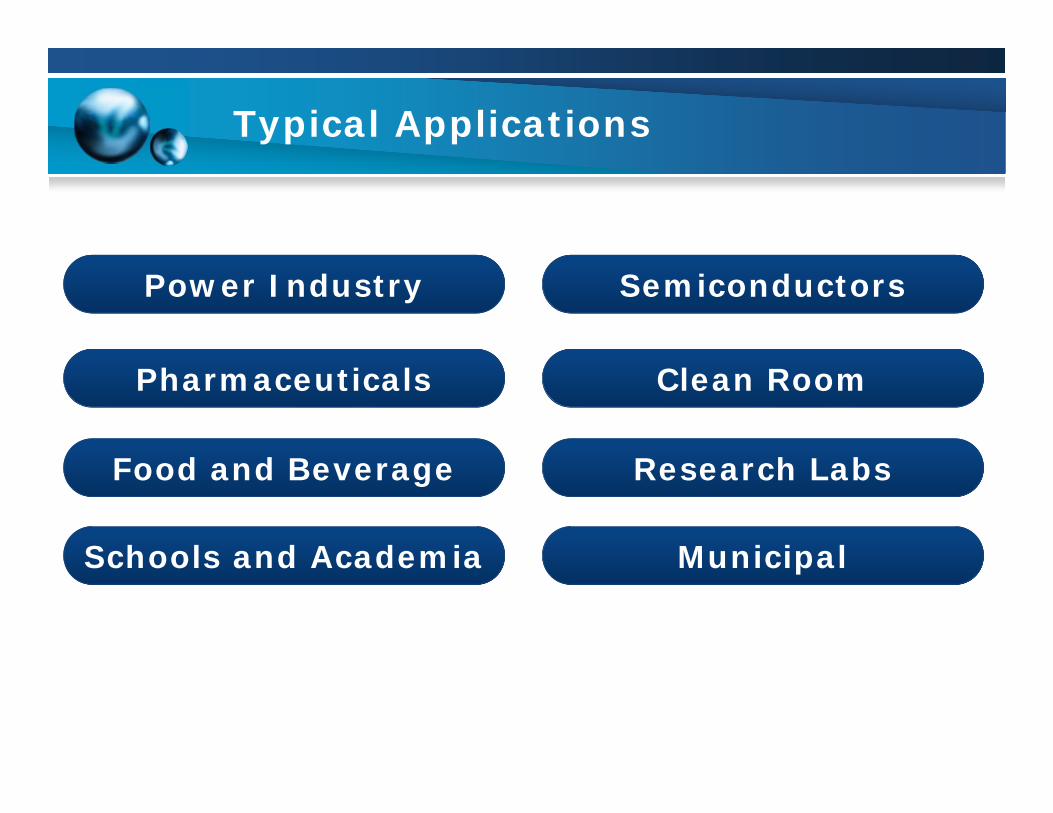
Typical Applications
SemiconductorsPower Industry
Food and Beverage Research Labs
Schools and Academia
Clean RoomPharmaceuticals
Municipal
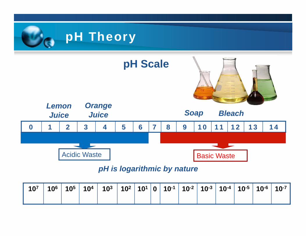
pH Theory
0 1 2 3 4 5 6 7 8 9 10 11 12 13 14
pH Scale
Basic WasteAcidic Waste
pH is logarithmic by nature
107 106 105 104 103 102 101 0 10-1 10-2 10-3 10-4 10-5 10-6 10-7
BleachOrange Juice
Lemon Juice Soap
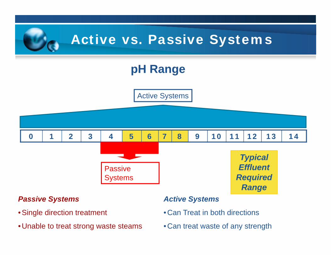
Active vs. Passive Systems
0 1 2 3 4 5 6 7 8 9 10 11 12 13 14
pH Range
Active Systems
Passive Systems
Passive Systems
•Single direction treatment
•Unable to treat strong waste steams
Active Systems
•Can Treat in both directions
•Can treat waste of any strength
Typical Effluent
Required Range

pH System Designs
There are three main styles of pH adjustment systems
•Flow through systems
•Batch treatment systems
•Hybrid flow/batch systems
pH System Design Flow Through Systems
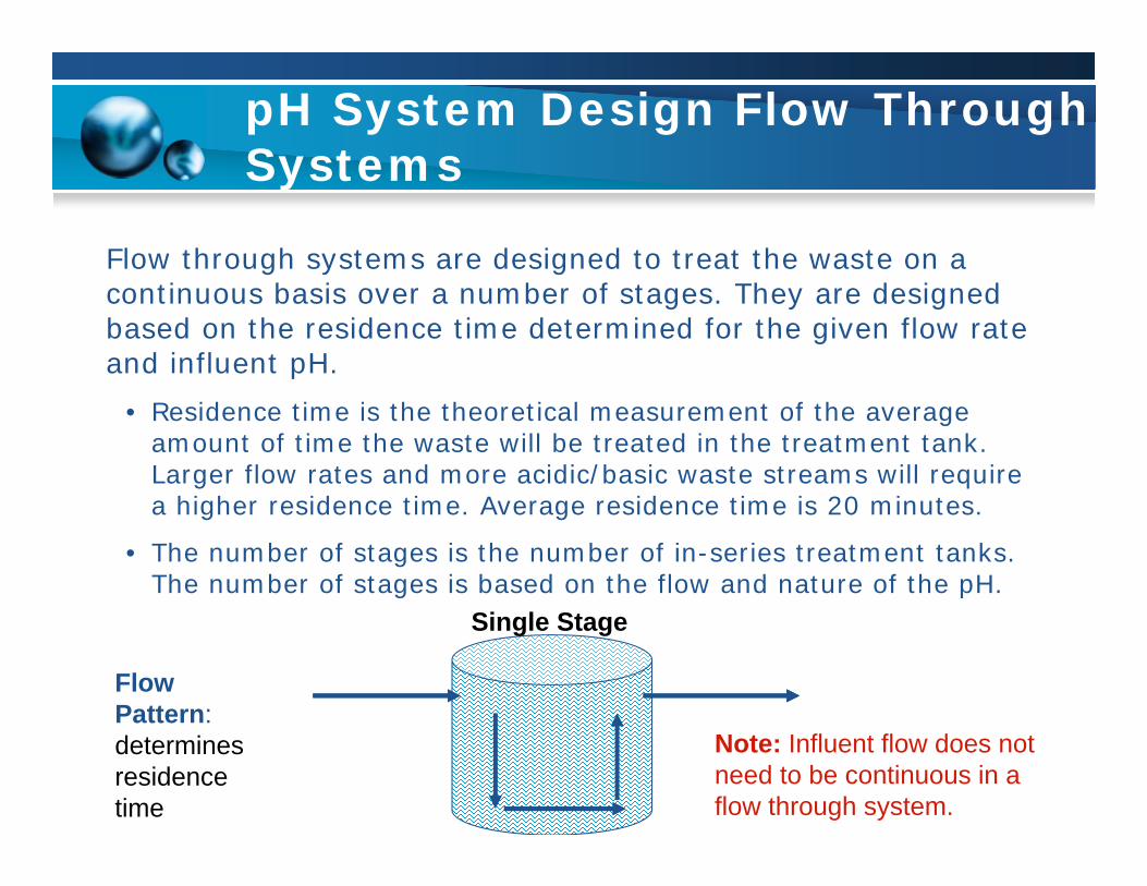
Flow through systems are designed to treat the waste on a continuous basis over a number of stages. They are designed based on the residence time determined for the given flow rate and influent pH.
• Residence time is the theoretical measurement of the average amount of time the waste will be treated in the treatment tank. Larger flow rates and more acidic/basic waste streams will require a higher residence time. Average residence time is 20 minutes.
• The number of stages is the number of in-series treatment tanks. The number of stages is based on the flow and nature of the pH.
Flow Pattern: determines residence time
Single Stage
Note: Influent flow does not need to be continuous in a flow through system.

pH System Design Flow Through

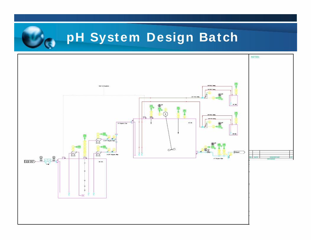
pH System Design Batch Systems
Batch systems are designed to treat a volume of waste until neutralized at which point the current batch is discharged and another batch volume is added to the system. Residence time is not a factor as the bath system treats the waste for as along as necessary.
• Batch systems have the advantage of being able to handle waste of essentially any pH. They also have no risk of producing out of compliance waste.
• Their primary disadvantage is they reduce throughput of the system.
Flow Inlet
Batch flow Pattern
Volume Held
Flow Transfer after treatment
pH System Design Batch

pH System Design Hybrid Systems (ACS)
Hybrid systems employ the benefits of the throughput capability of the flow through systems with the additional residence time and compliance control of batch systems. This is referred to as the Assured Compliance System (ACS).
The ACS provides an actuated valve on the discharge of the system.This valve will close if the effluent pH nears the discharge limits. The tanknormally only runs at partial capacity so when the discharge valve closes, itallows the system to operate for five minutes in a batch mode. Once the pHreturns to a normal range, the discharge valve will re-open and the system willcontinue to operate as a continuous flow through system. Should the pH notreturn to the desired range in time, an overflow at the top of the tank will bypassto drain or an optional recirculation or collection tank to prevent flooding of thesystem.

pH System Design Hybrid Systems (ACS)
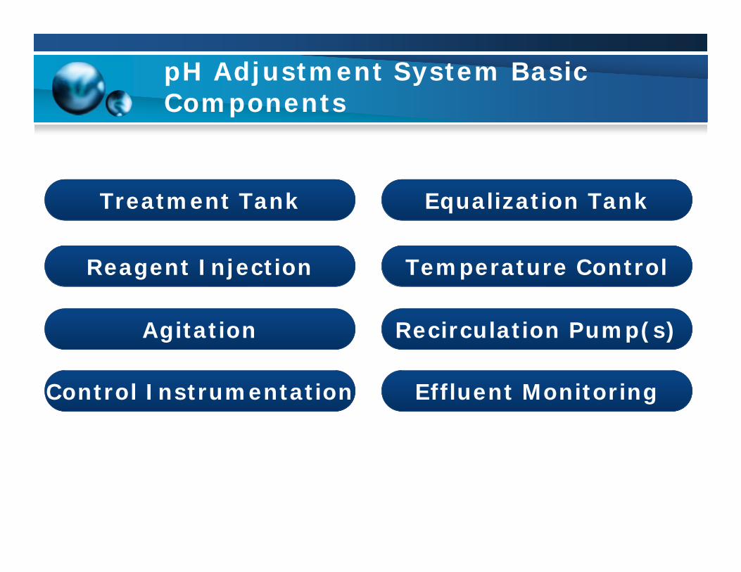
pH Adjustment System Basic Components
Equalization TankTreatment Tank
Agitation Recirculation Pump(s)
Control InstrumentationControl Instrumentation
Temperature ControlReagent Injection
Effluent Monitoring
pH Adjustment System Components Treatment Tanks/Agitation
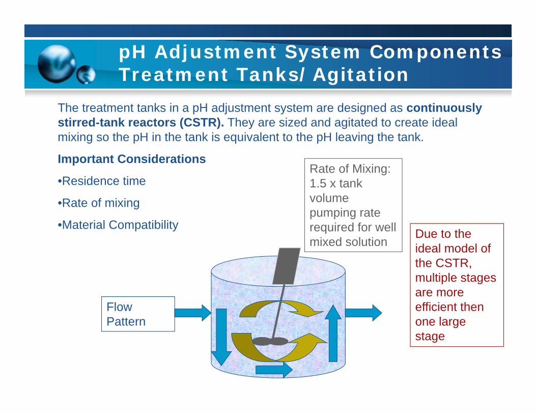
The treatment tanks in a pH adjustment system are designed as continuously stirred-tank reactors (CSTR). They are sized and agitated to create ideal mixing so the pH in the tank is equivalent to the pH leaving the tank.
Important Considerations
•Residence time
•Rate of mixing
•Material Compatibility
Flow Pattern
Rate of Mixing: 1.5 x tank volume pumping rate required for well mixed solution
Due to the ideal model of the CSTR, multiple stages are more efficient then one large stage

pH Adjustment System Components, chemical injection
Since a CSTR model allows for uniform pH across the treatment tank, reagent injection must be properly injected into the mixer wash and controlled to avoid swings in pH. The most common reagents for pH adjustment are sulfuric acid and sodium hydroxide. Additionally, carbon dioxide gas can be used.
Important Considerations
•Turn down for reagent injection proportional to logarithmic pH scale
•Careful not to oversize to avoid instability in controlling pH.
Standard Reagent assembly
Reagent injection
Mixer
pH Adjustment System Components, Instrumentation and Controls
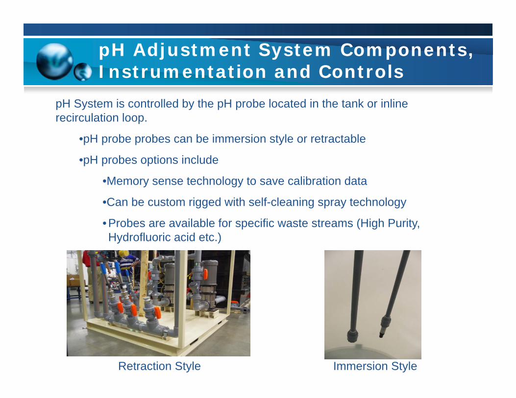
pH System is controlled by the pH probe located in the tank or inline recirculation loop.
•pH probe probes can be immersion style or retractable
•pH probes options include
•Memory sense technology to save calibration data
•Can be custom rigged with self-cleaning spray technology
•Probes are available for specific waste streams (High Purity, Hydrofluoric acid etc.)
Retraction Style Immersion Style
pH Adjustment System Components, Equalization Tanks
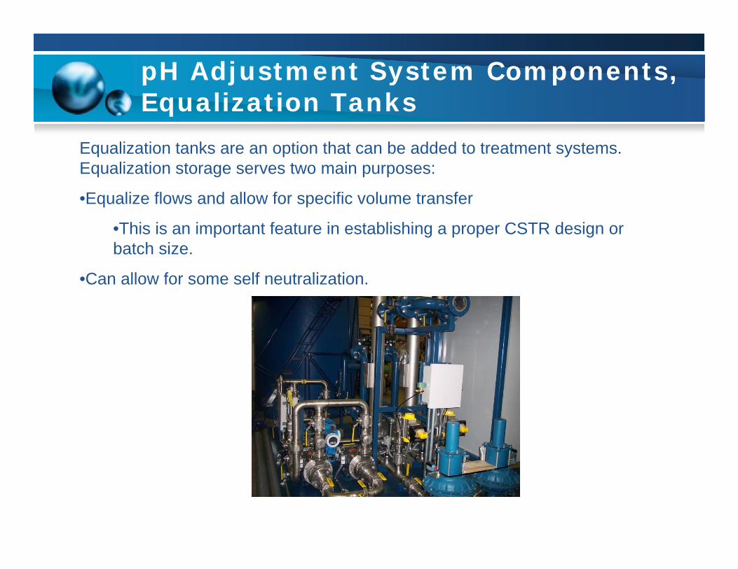
Equalization tanks are an option that can be added to treatment systems. Equalization storage serves two main purposes:
•Equalize flows and allow for specific volume transfer
•This is an important feature in establishing a proper CSTR design or batch size.
•Can allow for some self neutralization.

pH Adjustment System Components, Recirculation Pumps
Recirculation pumps are an option that can be added to treatment systems. Recirculation pumps serve three main purposes:
• They allow for use of retraction style pH probes which can be mounted at a more ergonomic level.
• The reagents can be injected inline, allowing for dilution and direct mixing into the mixer backwash.
• They can supplement mixing (but cannot be used in place of a mixer).

pH Design Considerations Influent pH
0 1 2 3 4 5 6 7 8 9 10 11 12 13 14
Influent pH dictates the number of stages for flow through systems and batch times for batch systems.
Reagent Grade Waste.
Reagent Grade Waste
Standard Acidic Waste Streams
Standard Basic Waste Streams
Reagent Grade Waste
•Waste Stream 1%+ acid/caustic
•Generally batch treatment only
•Requires in process temperature control to mitigate heat from neutralization reaction
•Treatment time is very long, residence time not applicable. Limiting temperature build-up dictates treatment time.
Standard Grade Waste
•Waste Stream 2-6 pH range
•Flow through, batch and hybrid systems applicable
•Residence time and number of stages based on flow rate and pH

pH Design Considerations Alkalinity
Alkalinity is a measure of buffering capability or the ability to neutralize acid and bases in a solution.
•Alkalinity is a major problem in high purity waste water (WFI, RODI etc.)
•Buffer injection will cut down on chemical use and treatment time
Buffering Range
1
7
14 Treatment Time
7
14
1
Treatment Time

pH System Control Schemes
There are two types of control schemes used in pH systems:
•Proportional control
•Titration based control
Proportional control is the more versatile of the control schemes. It is based on the logarithmic nature of pH and adjusts the chemical addition proportionally to the pH reading.
0 1 2 3 4 5 6 7 8 9 10 11 12 13 14
Caustic Pump Speed
Acid Pump
Speed
pH Scale
pH System Control Schemes Continued
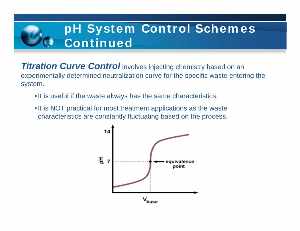
Titration Curve Control involves injecting chemistry based on an experimentally determined neutralization curve for the specific waste entering the system.
• It is useful if the waste always has the same characteristics.
• It is NOT practical for most treatment applications as the waste characteristics are constantly fluctuating based on the process.
pH System Sizing Flow through Systems
Assumptions:Lab Sink = 1 GPM
Cup Sink = 0.5 GPM
Fume Hood = 0.25 GPM
Actual Usage is 20% to 30% (Diversity)
Cage Washer, Autoclaves, and Dishwashers are assumed to operate at there maximum flow rates and are outside of normal diversity factors.
15 to 20 Minute Retention Time (in some cases more time is required).

pH System Sizing Flow through Systems Continued
Sample Calculation:
50 Lab Sinks X 1.0 GPM = 50 GPM
50 Cup Sinks X 0.5GPM = 25 GPM
20 Fume Hoods X 0.25 = 5 GPM
80 Total GPM X 25% Actual Usage = 20 GPM
2 Cage Washers at 10 GPM each. The diversity would assume only one is in operation at a time.
TOTAL System Flow: 30 GPM
30 GPM X 20 Minute Retention Time = 600 Treatment Tank ( (2) 300 gal. Tanks) Required.

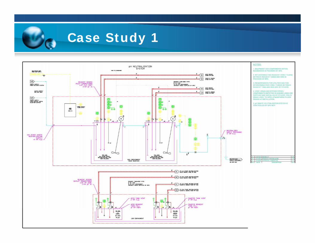
Case Study 1
Type: pH Adjustment System for College Biology Building.
Details:The system accepts waste from a 7 floor labbuilding. Total number of sinks and fumehoods are 105 and 20 respectively and (2)cage washers. The System is designed totreat 40gpm.
Unit Features:1. Dual stage pH system to account for aggressive waste streams.2. Two way pH control to treat both acid and alkaline waste.3. Effluent flow and pH monitoring.
Case Study 1

Case Study 2
Type: pH Adjustment System for Criminology Lab.
Details:The system accepts waste directly from thelab processes. Waste constituents include30% nitric acid, 10% hydrochloric acid, and10% hydrofluoric acid. The system isdesigned for safe treatment of thesechemistries using caustic reagent control andtemperature control with safety interlocks.The system is completely automated and user adjustable.The unit features:
1. All PVDF and PTFE wetted materials including adjustment tank and mixer coating2. Memory programmed pH holders that store calibration data between probe replacements3. Temperature safety interlocks4. Full PLC control with owner remote access and monitoring

Case Study 2
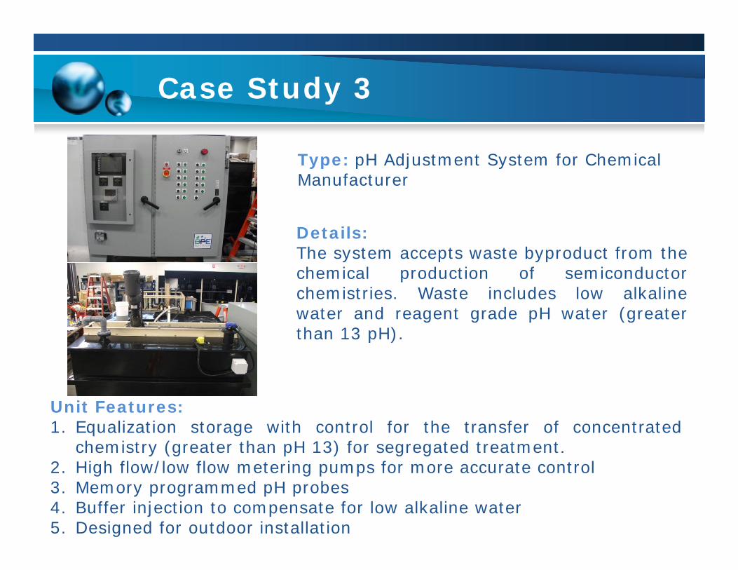
Case Study 3
Type: pH Adjustment System for Chemical Manufacturer
Details:The system accepts waste byproduct from thechemical production of semiconductorchemistries. Waste includes low alkalinewater and reagent grade pH water (greaterthan 13 pH).
Unit Features:1. Equalization storage with control for the transfer of concentrated
chemistry (greater than pH 13) for segregated treatment.2. High flow/low flow metering pumps for more accurate control3. Memory programmed pH probes4. Buffer injection to compensate for low alkaline water5. Designed for outdoor installation

Case Study 3

Case Study 3

Case Study 4
Type: Waste Treatment System for semi-conductor lab.
Details:The system treats semiconductor labwaste. The waste water is initially treatedfor particulate matter, organics, and thenmetals removal utilizing resin prior to pHadjustment.
Unit Features:1. Particulate filtration and organics removal2. Metals removal utilizing resin3. Buffer injection for low alkaline water4. Hybrid batch technology pH adjustment system

Case Study 4

Case Study 4

pH Adjustment System Questionnaire Burt Process Equipment
Determine water waste characteristics
Determine waste volume
Select type of system based on quantity and waste characteristics of water to be treated
pH System Selection Criteria
DateCompany Name
Contact NamePhone
Fax
Address
Additional Contact Info. Solution InformationChemical Composition
Temperature Range (°F)Solids in Suspension (PPM)?
Specific GravityOil and Grease Present
(PPM)?Available Utilities
Electrical (Voltage, Frequency, phase)
Compressed air (psig, SCFM)
Service Conditions (Batch Treatment Only)Total Accumulated
Flow/batch (gallons)Batch Frequency (#
batches/day or week)
Service Conditions (Continuous Treatment Only)Average Flowrate (gpm)
Maximum Flowrate (gpm)pH Range of Influent (min-
max)Desired Effluent pH Range
(min-max)
Service Conditions (Batch Treatment Only)-continued
List Any Concentrated Dumps to the SystemChemical Composition
Concentration (%)Volume (gallons)
Frequency of dumps (dumps/day, week, month)

Thank you
Questions?


![Wetted Mobile Packed Bed [Compatibility Mode]](https://static.documents.pub/doc/80x56/577c77921a28abe0548ca292/wetted-mobile-packed-bed-compatibility-mode.jpg)


