The phase shifts in external dielectric reflection were analyzed as a function of the incident angle. Thecontrast of the interference fringes formed between the incident and the reflected beams was considered. Forthe parallel mode the phase shift disappears between 450 and the Brewster angle. Experimental results areshown which demonstrate the contrast inversion in this region.
1. Introduction
In the description of interferometers by amplitudedivision, the light reflected from an optically densermedium is considered to undergo a phase shift of halfof a wavelength. As empirical grounds for this,Lloyd's experiment in the case of grazing incidenceand Newton's rings in the case of normal incidence areusually given. The theoretical explanation is given byFresnel's relations, which are obtained by solving theboundary conditions that must be satisfied by theelectric and magnetic fields at the surface of disconti-nuity. The deduction of these relations is treated inmany books on classical optics, such as Sommerfeld, 1
Born and Wolf,2 and Hecht and Zajac.3However, the treatment of this subject there is in-
complete if one wishes to calculate the contrast and thewidth of the fringes produced by the interference be-tween the reflected beam and the incident beam. Theproblem appears in the parallel mode, i.e., when theelectric field vector is parallel to the incident plane. Inthis case, one of the components suffers a phase shift ofhalf of a wavelength while the other does not, whichleads to an inversion of the sign of the reflection coeffi-cient in the Brewster angle.
In this work, the reflection coefficient is obtainedtaking these problems into account, and when thefringe contrast is then calculated it is found that forcertain values of the incident angle the phase shift
The authors are with University of Buenos Aires, Physics Depart-ment, 1428 Buenos Aires, Argentina.
observed under normal and grazing incidence is ab-sent. This result is confirmed by an experimentwhereby a photograph is obtained showing the shift ofa half-period in the fringe systems of the perpendicularand parallel modes for the same incident angle.
II. Fringe Systems from Interference Between Reflectedand Incident Beams
To describe the interference fringe system that isformed when the incident and reflected beams aresuperimposed, it is necessary to know the relative in-tensities and phases of the two beams. These areobtained by solving the boundary conditions for theelectric and magnetic fields. For this calculation, thecoordinate system of Fig. 1 was used. In this work welimit ourselves to the case in which the light passesfrom a less dense medium of index n to a more denseone of index n'. As is well known, the problem ofreflection and refraction of a plane wave may be sepa-rated into two modes of polarization, so we treat eachmode separately.
A. Perpendicular Mode
In this mode the electric field intensity vector () isperpendicular to the incident plane, and therefore themagnetic field intensity vector (f) is parallel to thatplane. Figure 1 shows the vectors corresponding tothe three waves: incident, reflected, and refracted.The components of the electric and magnetic fieldsare, therefore,
and where E and e' are the dielectric constants of theless dense and more dense media, respectively, and gand As' are the respective magnetic permeabilities; X isthe wavelength; w is the angular frequency; and N, N',and N'R are the unit vectors normal to the incident,refracted, and reflected wavefronts, respectively.
The boundary conditions that ensue from the conti-nuity of the tangential components of the vectors and I in the discontinuity plane may be written as
6,(X = ) + 6 RZ(X = 0) = 6,(X = 0),
W(X = 0) + Ry(X = ) = Wy(X = ).
(5)
(6)
Substituting the expressions for and I given inEqs. (1), (2), and (3) into these equations, the conditionof equality of the phases at the surface of discontinuityis found. From this condition the law of reflection andSnell's law are obtained. The boundary conditions forthe fields are then reduced to the following expres-sions:
A1 + C1 = B 1,
-E A 1 cosa + < C± cosa = - BjB cosf.
(7)
(8)
From the solution of this system the relationshipbetween the amplitudes of the incident and reflectedwaves is obtained:
Cl - sin(13-a)Al sin(# + a)
., R_- (c)
\\ ~~YAVi no n
Fig. 1. Vectors representing incident, reflected, and refracted lightin the incident plane: (a) postulated perpendicular mode; (b) pos-tulated parallel mode; (c) results for the parallel mode for angles
greater than and less than the Brewster angle.
that the reflected wave is 180° out of phase with re-spect to the incident wave.
With Snell's law and some trigonometric relations,the reflection coefficientR 1 may be written in terms ofthe angle a and the refractive indices in the followingform:
R = 2
n cosa + n 2 - n2 sin2a(11)
In Fig. 2 we showR 1 as a function of a for n = 1 and n'= 1.755. From this curve it may be observed that R increases in absolute value as a grows. In particular,
R = +~ , if a = 0°,ni + ni'
(9)
where RI is the reflection coefficient for the perpen-dicular mode.
From Snell's law, which links the angles a and i,n sina = n' sinfl, (10)
it may be seen that f: < a if n' > n, which is the case thatwe are analyzing; then RI is negative. This means
RI= -1 if a = 90°.
The parameters characterizing the fringe systemthat is formed in the (xy) plane by interference of theincident wave with the reflected wave are the coordi-nates of the light maxima and minima, fringe width,and contrast.
To calculate them we write the electric fields of thetwo waves taking into account the relationships be-
tween the amplitudes and phases in the (xy) plane,which are
27r'p = n-x Cosa - wt,
2irPR = -n x cosa - wt.
The corresponding electric fields are therefore
6 = A 1 exp (in- x cosa) exp(-iwt),
&R = R1 exp (-in X x cosa) exp(-iwt).
(12)
(13)
(14)
(15)
The electric field that results from their superimpo-sition is
61 z + ORz,
a = A 1 [exp (in 2 x cosa)
+ R 1 exp (-in 2 x cosa)] exp(-iwt),
and the light intensity obtained as the product of 6 with its complex conjugate is given by
I = 2(1 + 2) + 2A 2RI cos (n x cosa).
Calling Xmax and Xmin the coordinates where the inten-sity is maximum and minimum, respectively, we find
where
I,(xma.) = A (1 + R 2)-2A 2RI,
I±(Xmin) = A2 (1 + R' 1) + 2A R,
Xmax (21 + 1)A4n cosa
21X4n cosa
(16)
Fig. 2. Reflection coefficients as functions of the incident angle.
(17)
(18)
(19)
(20)
(21)
with I = 0,1,2,3 ....The width of the fringes, i.e., the distance between
maxima or minima, isFig. 3. Variation of the distance between fringes with the incident
angle in the (x,z) plane.
Figure 3 shows the curve that gives the width of thefringes on the (x,z) plane as a function of the incidentangle for the light from a He-Ne laser, i.e., with X =6328 A and n = 1. From this curve it may be seen thatfor normal incidence A = 0.32 ,um, which is far belowthe limit of visual resolution. Increasing the angle ofincidence the width of the fringes increases and tendsto infinity for a = 900. However, for values slightlybelow 900, the width of the fringes decreases rapidlyreaching a value of A = 0.52gm for a = 53°, which is thelimit of visual resolution.
We calculate the fringe contrast by the relation= Ij (Xma.) I (Xmin)
- Xma. + I(Xmin) (3
Replacing Il (xrx) and Ij (Xmin) by their expressionsgiven in Eqs. (18) and (19), one finds that
2RI
~1 1 + R2(24)
With the expression for R 1 given in Eq. (11), onefinally obtains
l = + 2 2flI n 2 + fl2 - 2n 2 sin'a (25)
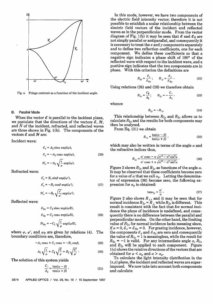
The variation of -y± with the incident angle a for n = 1and n' = 1.755 may be seen in Fig. 4.
Fig. 4. Fringe contrast as a function of the incident angle.
B. Parallel Mode
When the vector 6 is parallel to the incident plane,we postulate that the directions of the vectors , ,and N of the incident, refracted, and reflected wavesare those shown in Fig. 1(b). The components of thevectors 6 and I are:
Incident wave:
& = All sina exp(i'p),
= -A,, cosa exp(iO), (26)
= -All I exp(ip).
Refracted wave:
&x = B,, sin# exp(ip'),
6y = -Bl cos exp(io'), (27)
Kf = -B,, exp(ip').
Reflected wave:
&Rx = C sina exp(ipR),
6Ry = C cosa exp(ioR), (28)
WRz = -C11 F exp(i,R),
where s, so', and PR are given by relations (4). Theboundary conditions are, therefore,
-All cosa + C cosa = -BII cosfl, (29)
All + Cl 6 = B 4 * (30)
The solution of this system yieldsCii tan(a-A) (31)
All tan(a + 3)
In this mode, however, we have two components ofthe electric field intensity vector; therefore it is notpossible to establish a scalar relationship between theelectric field vectors of the incident and reflectedwaves as in the perpendicular mode. From the vectordiagram of Fig. 1(b) it may be seen that 6 and 6' R arenot simply parallel or antiparallel, and consequently itis necessary to treat the x and y components separatelyand to define two reflection coefficients, one for eachcomponent. We define these coefficients so that anegative sign indicates a phase shift of 180° of thereflected wave with respect to the incident wave, and apositive sign indicates that the two components are inphase. With this criterion the definitions are
Rl II = '6R; Rlly = 6R
Using relations (26) and (28) we therefore obtain
C11 i R - C1RlX=All; Ry=All'
whence
Rlly= -Rllx
(32)
(33)
(34)
This relationship between RI1y and RIIx allows us tocalculate RIIx and the results for both components maythen be analyzed.
From Eq. (31) we obtain
- tan(a -)tan(a + ) (35)
which may also be written in terms of the angle a andthe refractive indices thus,
RIIx n' cosa-fn VW'2 -2 n2a
n' cosa + n Vn 2 -nsia(36)
Figure 2 shows RIx and Rily as functions of the angle a.It may be observed that these coefficients become zerofor a value of a that we call ap. Letting the denomina-tor of expression (36) become zero, the following ex-pression for ap is obtained:
n/tanap =--fi (37)
Figure 2 also shows RI, and it may be seen that fornormal incidence RIly = R 1 while RIIx is different. Thisresult is consistent with the fact that for normal inci-dence the plane of incidence is undefined, and conse-quently there is no difference between the parallel andperpendicular modes. On the other hand, the limitingvalue of RIIx for normal incidence lacks meaning since,if a = 0, 6 x = 6 Rx = 0. For grazing incidence, however,the components 6 y and &Ry are zero and consequentlythe value of R Iy = 1 is meaningless, while the result forRI1, = -1 is valid. For any intermediate angle ax, RXand R11y will be applied to each component. Figure1(c) shows the relative directions of the vectors that areobtained for c < axp and a > cap.
To calculate the light intensity distribution in the(x,z) plane, the incident and reflected waves are super-imposed. We now take into account both componentsand calculate
With the help of relations (4), (26), (28), and (32) weobtain
l = All sina [exp (in Av x cosa)
+ RIIx exp (in 2A x cosa)] exp(-iwt),
011Y = -All cosa exp (in A x cosa)
7/2
5/2
3/2 A
1/2 8=
(40)
(a)
1 ~ ~~~~~~~~ AE
A+~~~~~~~~Z 3^
X _Iz
(b)
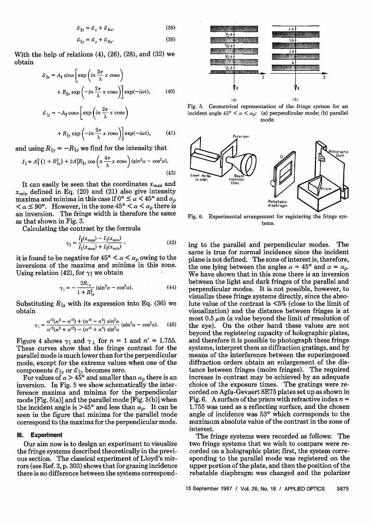
Fig. 5. Geometrical representation of the fringe system for anincident angle 450 < a < as,: (a) perpendicular mode; (b) parallel
mode.
+ RIIY exp -in Av x cosa)] exp(-iwt),
and using Rily = -Rx we find for the intensity that
III = Aj2 (1 + Rift) + 2Ai2lR ii cos (n A x cosa) (sin 2a - cos2 a).
(42)
It can easily be seen that the coordinates Xmax andXmin defined in Eq. (20) and (21) also give intensitymaxima and minima in this case if 00 < cx < 450 and cap< a < 900. However, in the zone 450 < a < cxp there isan inversion. The fringe width is therefore the sameas that shown in Fig. 3.
Calculating the contrast by the formulaIII(Xmax) - III(Xmin) (43)
IYII = (Xm.) + III (Xmin)
it is found to be negative for 450 < a < cap owing to theinversions of the maxima and minima in this zone.Using relation (42), for yl we obtain
7Il - 12R (sin2a - COS2 a). (44)1+ Rlax
Substituting Rijx with its expression into Eq. (36) weobtain
Figure 4 shows yj1 and -y for n = 1 and n' = 1.755.These curves show that the fringe contrast for theparallel mode is much lower than for the perpendicularmode, except for the extreme values when one of thecomponents g lx or &Ily becomes zero.
For values of cx > 450 and smaller than Cap there is aninversion. In Fig. 5 we show schematically the inter-ference maxima and minima for the perpendicularmode [Fig. 5(a)] and the parallel mode [Fig. 5(b)] whenthe incident angle is >450 and less than cxp. It can beseen in the figure that minima for the parallel modecorrespond to the maxima for the perpendicular mode.
11. Experiment
Our aim now is to design an experiment to visualize*the fringe systems described theoretically in the previ-ous section. The classical experiment of Lloyd's mir-rors (see Ref. 3, p. 303) shows that for grazing incidencethere is no difference between the systems correspond-
oH ogaphicD 142. 'O IO ~p Ia te
Laser He e (4 mW) expander <;I> I IIfilter U > F I
Rebaabtediaphragm
Fig. 6. Experimental arrangement for registering the fringe sys-tems.
ing to the parallel and perpendicular modes. Thesame is true for normal incidence since the incidentplane is not defined. The zone of interest is, therefore,the one lying between the angles cx = 450 and cx = cxp.We have shown that in this zone there is an inversionbetween the light and dark fringes of the parallel andperpendicular modes. It is not possible, however, tovisualize these fringe systems directly, since the abso-lute value of the contrast is <5% (close to the limit ofvisualization) and the distance between fringes is atmost 0.5 gm (a value beyond the limit of resolution ofthe eye). On the other hand these values are notbeyond the registering capacity of holographic plates,and therefore it is possible to photograph these fringesystems, interpret them as diffraction gratings, and bymeans of the interference between the superimposeddiffraction orders obtain an enlargement of the dis-tance between fringes (moire fringes). The requiredincrease in contrast may be achieved by an adequatechoice of the exposure times. The gratings were re-corded on Agfa-Gevaert 8E75 plates set up as shown inFig. 6. A surface of the prism with refractive index n =1.755 was used as a reflecting surface, and the chosenangle of incidence was 530 which corresponds to themaximum absolute value of the contrast in the zone ofinterest.
The fringe systems were recorded as follows: Thetwo fringe systems that we wish to compare were re-corded on a holographic plate; first, the system corre-sponding to the parallel mode was registered on theupper portion of the plate, and then the position of therebatable diaphragm was changed and the polarizer
Fig. 7. Experimental arrangement for photographing the moirefringe systems.
Holographicplate
WavefrontFig. 8. Diffraction of light in the plates where the fringe systems are
registered, giving rise to moire fringe systems.
was rotated to expose the lower portion with lightpolarized perpendicular to the incident plane. Thusthe two fringe systems are adjacent to each other,allowing them to be easily compared. The rebatablediaphragm was then removed, and another gratingwith polarization perpendicular to the incident planewas registered on another holographic plate. Thisgrating provided the reference beam allowing thefringe systems registered on the first plate to be com-pared.
To obtain a photograph allowing the two fringe sys-tems registered on the first plate to be visualized, theexperimental arrangement shown in Fig. 7 was used.The parallel beam, leaving the beam expander, incidedon the plate containing the fringe systems to be visual-ized. Since the fringe systems registered on the platesbehave as diffraction gratings, the light transmitted bythese gratings gives diffraction orders such that thezero order lies in the same direction as the incidentbeam, and the first order, lying in a different direction,is formed by two adjacent beams, one for each grating.There is a phase difference of half of a wavelengthbetween these two beams. Part of the parallel beamwhich is not diffracted in the first grating (zero order)will be diffracted in the grating registered on the sec-
F1iflfl1I11{1IH51Fig. 9. Photograph of the moire fringe systems corresponding tothe parallel mode (above) and the perpendicular mode (below) for
a = 53°.
ond plate which lies immediately behind the first (Fig.8). Thus another beam diffracted to first order isobtained, which, unless fine adjustments are made,will not be exactly parallel to the first-order beamsfrom the first plate. The interference between thefirst order from the first plate and from the secondplate will give two systems of interference fringes, onefor the parallel mode and the other for the perpendicu-lar mode. These fringe systems will be parallel to eachother and displaced by half of the distance betweenfringes. By adjusting the relative position of theplates, which is carried out by rotating them in theirown plane and varying the paper strips that are placedbetween them, they may be oriented and the spacingbetween them may be adjusted. This was the proce-dure used to obtain Fig. 9 where the shift between thetwo systems calculated in the previous section may beappreciated.
IV. Conclusions
When a plane wave is reflected by a dielectric sur-face the electric field intensity vectors of the incidentand reflected waves are related by a tensor. Owing tothe symmetry conditions this tensor is diagonal, andtwo of its elements differ only in their sign. Thesediagonal elements are the reflection coefficients RIR i1, and R11y, with R ii = -R 11y. The calculations andthe experiment presented here show that in amplitudedivision interferometers that make use of dielectricreflection on an optically denser medium suffer aphase shift of half of a wavelength for incident angles<450 and greater than the Brewster angle. For inci-dent angles between 450 and the Brewster angle thephase shift of half of a wavelength is produced only forlight polarized perpendicular to the incident plane,while the light polarized parallel to the incident planedoes not undergo a phase shift. The opposed behaviorof the two components of the electric vector introducesa decrease in the contrast, but the maxima and minimaof the fringe systems are such that a shift by half of a
period is observed between the parallel and perpendic-ular modes, which indicates that in the parallel mode,the reflected light does not suffer a phase shift forangles between 450 and the Brewster angle.
The authors are indebted to Ricardo Banilis whoprovided the prism, to Marta Pedernera for the draw-ings, and to Ricardo Dato for copying the photographs.
This work was supported by CONICET and by agrant from the University of Buenos Aires.
References1. A. Sommerfeld, Vorlesungen uber Theorestische Physik, Band 4.
"Optik" (Akademische Verlagsgesellschaft, Leipzig, 1959).2. M. Born and E. Wolf, Principles of Optics (Pergamon, Oxford,
1975).3. E. Hecht and A. Zajac, Optics (Addison-Wesley, Reading, MA,
1974).
OSAANNUALMEETING
SeattleSome participants from
the University ofRochester
G. M. Morris Carlos R. Stroud, Jr.
M. G. Rymer J. H. Eberly
photos:W. J. TomlinsonBell Communications Research