Phase transitions in ferroelectric-paraelectric superlatticesA. P. Levanyuk and I. B. Misirlioglu Citation: J. Appl. Phys. 110, 114109 (2011); doi: 10.1063/1.3662197 View online: http://dx.doi.org/10.1063/1.3662197 View Table of Contents: http://jap.aip.org/resource/1/JAPIAU/v110/i11 Published by the American Institute of Physics. Related ArticlesModeling the switching kinetics in ferroelectrics J. Appl. Phys. 110, 114106 (2011) Ferroelectric phase transition and low-temperature dielectric relaxations in Sr4(La1xSmx)2Ti4Nb6O30 ceramics J. Appl. Phys. 110, 114101 (2011) Poling temperature tuned electric-field-induced ferroelectric to antiferroelectric phase transition in0.89Bi0.5Na0.5TiO3-0.06BaTiO3-0.05K0.5Na0.5NbO3 ceramics J. Appl. Phys. 110, 094109 (2011) Structural transitions and enhanced ferroelectricity in Ca and Mn co-doped BiFeO3 thin films J. Appl. Phys. 110, 094106 (2011) Measurements and ab initio molecular dynamics simulations of the high temperature ferroelectric transition inhexagonal RMnO3 J. Appl. Phys. 110, 084116 (2011) Additional information on J. Appl. Phys.Journal Homepage: http://jap.aip.org/ Journal Information: http://jap.aip.org/about/about_the_journal Top downloads: http://jap.aip.org/features/most_downloaded Information for Authors: http://jap.aip.org/authors
Downloaded 05 Dec 2011 to 193.255.135.1. Redistribution subject to AIP license or copyright; see http://jap.aip.org/about/rights_and_permissions
Phase transitions in ferroelectric-paraelectric superlattices
A. P. Levanyuk1,2,3 and I. B. Misirlioglu1,a)
1Faculty of Engineering and Natural Sciences, Sabanci University, Tuzla/Orhanli, 34956, Istanbul, Turkey2Moscow Institute of Radioengineering, Electronics and Automation, Moscow 117454, Russia3Departamento de Fisica de la Materia Condensada, C-III, Universidad Autonoma de Madrid, 28049 Madrid,Spain
(Received 26 May 2011; accepted 19 October 2011; published online 5 December 2011)
Within the phenomenological Landau–Ginzburg–Devonshire theory, we discuss the paraelectric-
ferrolectric transition in superstructures consisting of ferroelectric and paraelectric layers of equal
thickness. The polar axis of the ferroelectric is perpendicular to the layer plane as expected in fully
strained BaTiO3/SrTiO3 superstructures on SrTiO3 substrates with pseudomorphic electrodes. We
concentrate on the electrostatic effects and do not take into account the boundary conditions other
than the electrostatic ones. We find that when the ferroelectric phase transition in the superstructures
is into a multidomain state, both its temperature and its character, i. e., the profile of the polarization
appearing at the phase transition is strongly influenced by the nature of the near-electrode region.
This is also the case for the layer thickness separating the single-and multidomain regimes of the
transition. Such a finding makes us question the idea that these superstructures can be thought of
as infinite systems, i.e., periodic superstructures similar to a crystal. The irrelevance of this idea in
certain conditions is demonstrated by comparing the phase transitions in two different superstructures
consisting of ferroelectric and paraelectric layers of the same thickness. In one of them, the
ferroelectric layer is in immediate contact with an ideal metallic electrode, whereas at the other
boundary, it is the paraelectric layer that is in contact with the electrode. In another superstructure,
one paraelectric layer is split in two equal parts which are placed as the first and last layer between
the electrodes and the ferroelectric layers which are closest to the electrodes. We show (with some
formal reservations) that the phase transition temperature in the first superstructure can be over
100 �C more than in the second one if the material parameters of BaTiO3/SrTiO3 are used for the
estimations. Moreover, the profile of the polarization arising at the phase transition is inhomogeneous
along the superstructure and has the maximum amplitude in the ferroelectric layer contacting the
electrode. We argue that this situation is general and results in smearing of the phase transition
anomalies for the layer thicknesses corresponding to multidomain transitions. The work is mainly
analyical but numerical methods have been used to support some statements that have been put
forward as hypotheses. VC 2011 American Institute of Physics. [doi:10.1063/1.3662197]
I. INTRODUCTION
Currently there is a lot of attention devoted to
ferroelectric-paraelectric superlattices.1–8 However, the phe-
nomenological theory of phase transitions in these systems is
still far from being complete and consistent. This may seem
surprising because the theory of these systems started9–12
well before the first experimental realization of the superlatti-
ces.13,14 Earlier theoretical works were based on the consider-
ation that the ferroelectric polarization was parallel to the
plane of the structure. This was both natural and correct
because the authors considered superlattices consisting of
layers of cubic ferroelectrics with the layer plane perpendicu-
lar to a cubic axis. It was correct to expect that the ferroelec-
tic polarization would be directed along a cubic axis parallel
to the layer plane because there was no depolarizing field in
this configuration. Multilayers in experimental studies do not,
however, usually consist of cubic ferroelectric materials [see
Refs. 1–8; because of the misfit strains, the cubic paraelectric
phase transforms into (at least) a tetragonal state either with
the polar axis perpendicular to the layer plane (uniaxial
ferroelectric) or with two polar axes parallel to the plane
(two-axial ferroelectric]. In this paper, we are focusing on the
former, uniaxial case, which seems to be the main interest for
experimental works. Because the ferroelectric polarization is
perpendicular to the interface, the depolarizing field deter-
mines both the temperature and the character of the ferroelec-
tric phase transition. Thus the non-electrostatic effects at the
interface (“short-range interlayer interaction”), which was
the main emphasis in Refs. 9–12, become of secondary
importance. This reasonable idea was pursued in Refs. 15 and
16 in which the authors discussed one aspect of the depolariz-
ing field: Lowering of the temperature of the ferroelectric
phase transition into the single domain state, which is an
effect known, in principle, since the work of Batra et al.17 In
other words, the authors took for granted that the ferroelectric
phase transition was into a single domain state. There is,
however, another possibility: That this transition could be
into a multidomain state. It should be noted that the interplay
between single- and multidomain transitions in a ferroelectric
slab between metallic electrodes with two dielectric layers
between the ferroelectric and the electrodes has beena)Electronic mail: [email protected].
0021-8979/2011/110(11)/114109/14/$30.00 VC 2011 American Institute of Physics110, 114109-1
JOURNAL OF APPLIED PHYSICS 110, 114109 (2011)
Downloaded 05 Dec 2011 to 193.255.135.1. Redistribution subject to AIP license or copyright; see http://jap.aip.org/about/rights_and_permissions
discussed in some detail by Chensky and Tarasenko (ChT)18
in their 1982 paper. The very same approach of ChT has been
used by Stephanovich et al.19 to discuss the ferroelectric
phase transitions in multilayers of the type we are analyzing.
In their work, they supposed that the spatial distribution of
the ferroelectric polarization appearing as a result of the
phase transition is periodic along the superstructure. This
analogy with ordinary crystals looks quite natural, and it is
not surprising that other research groups have adopted this
assumption.19,20 In our work, using the same approach as in
Ref. 19, we show that the periodicity assumption along the
out-of-plane direction is not justified. We consider two spe-
cific cases of superstructures. For one of them, we explicitly
show that assuming periodicity may not hold regardless of
the system size. For another special case, the assumption of
periodicity seems to be, hypothetically, correct but this sys-
tem is a very specific case.
The physical reason prohibiting the periodicity assump-
tion is that the superstructure is never sufficiently thick to con-
sider it as an analog of a periodic crystal. Experimentally, the
lateral sizes of the electrode or external surface are always
much larger than the total thickness of the superstructure.
Theoretically, this corresponds to the supposition that the
layers are laterally infinite. Therefore, no point or region
inside of the superstructure is “sufficiently far” from the boun-
daries. At the same time, the structure of the boundary layers
strongly influences how the depolarizing field is compensated,
and this impacts the whole system. To show this, we compare
the phase transitions in two different superstructures consist-
ing of ferroelectric and paraelectric layers of the same thick-
ness. One of these structures has the ferroelectric layer in
immediate contact with an ideal metallic electrode, while at
the other boundary, it is a paraelectric layer that is in contact
with the electrode. We name such a stack of layers a system
consisting of bilayer cells. In the other superstructure, one
paraelectric layer is split in two equal parts that are situated
between the electrodes and ferroelectric layers. We also name
such a stack of layers starting with half a paraelectric layer
contacting one electrode and ending again with half a para-
electric layer before the other electrode a system consisting of
ChT cells. We were unable to rigorously analyze the phase
transitions in the two systems. However, we were able to
show that the phase transitions are very different both in terms
of the transition temperatures and the profile of the space dis-
tribution of ferroelectric polarization arising at the transition.
The sensitivity of the phase transition to the characteris-
tics of the near-electrode region forces us to be cautious about
comparison of the experimental data with theoretical formulae
for idealized models. That is why we do not try to make this
comparison, although, for the sake of illustration, we use in
our plots the physical parameters of BaTiO3-SrTiO3 super-
structures. To be able to produce results comparable to experi-
ments, the theory should consider further developments, and
we see our paper as no more than a step in this direction.
Throughout the paper we shall not take into account the
non-electrostatic boundary conditions at the ferroelectric-
paraelectric interfaces, similar to ChT18 and unlike Stephano-
vich et al. 19 There is no doubt that for a realistic comparison
with experiments, these conditions should be taken into
account. But this paper is devoted mainly to conceptual prob-
lems, which, as we have already mentioned, prove to be fairly
difficult by themselves. That is why we prefer not to divert
the reader’s attention from these conceptual problems. The
only parameter that we shall try to calculate in this paper is
the phase transition temperature for different total thicknesses
of the pair of the layers in the superstructures. We shall also
analyze the form of the polarization profile setting in at the
phase transition.
The paper is organized as follows: In Sec. II, we con-
sider small systems consisting of either two or three ferro-
electric/paraelectric layers. We begin this part by describing
the ChT results relevant to what is considered in this paper.
Also, we apply their approach to other three or two layer sys-
tems as a preparation to analyze the systems given in the
next section. In Sec. III, we try to understand what happens
in large systems, considering first doubled “small systems”
and then generalizing some of the results to systems of
arbitrary length. The physical conclusions we arrive at using
the obtained results are discussed in Sec. IV. In Sec. V, we
summarize the results of our paper.
II. SMALL SYSTEMS
A. The Chensky and Tarasenko approach
The system ChT studied is illustrated in Fig. 1. Upon
cooling, the ferroelectric phase transition in this system may
be either into single or multidomain states. Naturally, when
the thickness of the paraelectric (“dead”) layers is suffi-
ciently small, the transition will be into single domain state.
ChT calculated the maximum dead layer thickness (dc) for
this phase transition. They studied in detail only the case
where the dead layer thickness is much smaller than the film
thickness. For this case, dc proved to be independent of the
ferroelectric slab thickness but depended on ferroelectric ma-
terial constants and the dielectric constant of the paraelectric
layer.21 We are interested in the case where the two thick-
nesses are comparable. Nevertheless, some general formulae
of ChT are relevant to our case also, and the phenomena in
the cases of thin and thick dead layers for similar systems
prove to be qualitatively similar. That is why it makes sense
to discuss some of the ChT results and describe their proce-
dure to some extent.
Note that for d> dc where the phase transition is into a
multidomain state, they found that two types of domain struc-
tures appear. If d� dc< dc, the period of the domain structure
is larger than the thickness of the ferroelectric slab (“wide
FIG. 1. (Color online) Schematic of the ferroelectric layer with thin dead
layers having thickness d/2 between the ferroelectric and the electrode. This
was the system that was investigated in Ref. 18.
114109-2 A. P. Levanyuk and I. B. Misirlioglu J. Appl. Phys. 110, 114109 (2011)
Downloaded 05 Dec 2011 to 193.255.135.1. Redistribution subject to AIP license or copyright; see http://jap.aip.org/about/rights_and_permissions
domains,” WD); for d� dc> dc, this period is less than the
thickness (“narrow domains,” ND). In Ref. 19, these two
regimes were called “strong coupling” and “weak coupling”
regimes. In this work, we will show that in the case of suffi-
ciently large dielectric constant of the paraelectric layer, one
has to distinguish between the two different ND regimes.
To find the phase transition temperature, ChT studied
stability of the paraelectric phase. The mathematical indica-
tion of a loss of stability of a state (phase) was obtained by
studying solutions of an appropriate system of linear differ-
ential equations along with relevant boundary conditions.
This method dates back to a paper by Suhl,22 who used it in
another problem. The paraelectric phase is stable when the
only possible solution is zero (trivial). Appearance of non-
zero (non-trivial) solutions indicates a way of loss of stability
of the phase, and specifically this loss is with respect to a
form of the ferroelectric polarization distribution that is rep-
resented by the solution. Within this approach, such a formu-
lation of the problem results in infinite number of ways of
stability loss represented by an infinite set of the polarization
profiles. Of course, they are not real and are virtual possibil-
ities of the stability loss. The loss of stability of the paraelec-
tric phase, corresponding to the theoretically found phase
transition, occurs with respect to a single form chosen from
these infinite number of virtual solutions. The criterion of the
choice is that the loss of stability of the paraelectric phase
with respect to this solution occurs earliest, i.e., it corre-
sponds to the highest temperature.
Similar to ChT we shall suppose that both the ferroelec-
tric and paraelectric layers are isotropic in the x-y plane.
Then the nontrivial inhomogeneous solutions at the stability
loss appear simultaneously for all the directions in this plane.
That is why it is sufficient to consider inhomogeneities along
one direction only, which we identify as the x axis. Thus the
problem is reduced to solving the equations in the x-z plane.
The system of linear differential equations mentioned here
includes the linearized constituent equation for the ferroelec-
tric polarization (Pz)
APz � g@2Pz
@x2� g
@2Pz
@z2¼ Ez; (1)
where Ez is the electric field along z axis. Other equations
should also be included to account for an (indirect) influence
of Pz on other degrees of freedom. The most important of
them is the polarization along x (nonferroelectric) axis.
Because Ez (x) implies the presence of Ex via the electrostatic
equation curlE¼ 0, one has to take into account the Ex com-
ponent together with the polarization, which we shall implic-
itly include by introducing the dielectric constant e? along
the plane of the structure. The electric field due to the
ferroelectric polarization exists, of course, also in the para-
electric, which we consider as isotropic with the dielectric
constant ep. The system of equations become complete by
adding div D¼ 0, where D¼ e0epE in the paraelectric and
D ¼ e0e?Ex; 0; e0ebEz þ Pzð Þ in the ferroelectric layer. In the
latter formula, we have introduced the so-called “base” or
“background” dielectric constant, eb, which is assumed to
reflect the fact that Pz is not the total z component of the
polarization but is only the “soft part,” which corresponds to
the order parameter.23 In this way, we take into account
more non-ferroelectric degrees of freedom.
Because we are considering an infinite slab, we can
present the x dependence of all the functions in form of a
Fourier series: Pz(x, z)¼RkPzk(z) cos kx and u(x, z)¼Rkuk(z) cos kx to allow the system of the partial differential
equations to be reduced to systems of ordinary differential
equations. We work with the electrostatic potential u(x, z) as
it is convenient to use this instead of the electric field. In
addition, following ChT, we put g¼ 0 in Eq. (1); this consid-
erably simplifies the mathematics and makes it possible to
take into account the electrostatic boundary conditions only,
which we have already commented on in Sec. I. Inserting the
Fourier form of the polarization and the electrostatic poten-
tial into Eq. (1), we obtain an algebraic equation:
Aþ gk2� �
Pzk ¼ �duk
dz(2)
and for a given k the electrostatic equation div D¼ 0
acquires now the form
ek
d2ufk
dz2� e?k2ufk ¼ 0; (3)
where
ek ¼ eb þ 1=e0 Aþ gk2� �
(4)
for the ferroelectric and subscript f implies the ferroelectric
layer. For the paraelectric layer, we have
d2upk
dz2� k2upk ¼ 0 (5)
where p implies the paraelectric layer.
Because of the symmetry of the system, we establish
that there are two families of solutions: symmetric and anti-
symmetric with respect to reflection in the mirror plane at
z¼ 0. ChT considered antisymmetric solutions only guided
by physical arguments. We shall consider both families of
solutions to illustrate our treatment of larger systems where
these two solutions can, in principle, compete in terms of the
earlier stability loss. In both cases, one can use the boundary
conditions at two of the four interfaces, e.g., at z¼ l/2 and
z¼ (lþ d)/2:
uk lþ dð Þ=2ð Þ ¼ 0; (6)
uk l=2þ 0ð Þ ¼ uk l=2� 0ð Þ; (7)
ekduk
dzl=2� 0ð Þ ¼ ep
duk
dzl=2þ 0ð Þ: (8)
One can show that for ek> 0 no nontrivial solution of either
family is possible, i.e., the nonpolar phase is stable. For
ek< 0, we begin with the antisymmetrical case looking for
solutions in the form ufk (z)¼C sin qz, where
q ¼ kffiffiffiffiffiffiffiffiffiffiffiffiffiffie?=jekj
p(9)
114109-3 A. P. Levanyuk and I. B. Misirlioglu J. Appl. Phys. 110, 114109 (2011)
Downloaded 05 Dec 2011 to 193.255.135.1. Redistribution subject to AIP license or copyright; see http://jap.aip.org/about/rights_and_permissions
for the ferroelectric and upk (z)¼F sinh k (z� (lþ d)/2) for
the paraelectric. Equations (7) and (8) attain the form
C sin ql=2þ F sinh kd=2 ¼ 0; (10a)
Cekq cos ql=2� Fepk cosh kd=2 ¼ 0: (10b)
Non-trivial solutions for Equations (10a) and (10b) exist if
tan ql=2 ¼ffiffiffiffiffiffiffiffiffiffiffijekje?
p=ep
� �tanh kd=2: (11)
In the limit of d !1, this formula becomes
tan ql=2 ¼ffiffiffiffiffiffiffiffiffiffiffijekje?
p=ep; (12)
which is relevant to phase transition into multidomain state
in a non-electroded slab in an infinite medium with the
dielectric constant ep. We shall repeatedly revisit this for-
mula throughout this paper.
For the symmetrical case instead of Eq. (11), we start
from ufk (z)¼C cos qz. Then instead of Eqs. (10a) and
(10b), we have
C cos ql=2þ F sinh kd=2 ¼ 0; (13a)
Cekq sin ql=2þ Fepk cosh kd=2 ¼ 0; (13b)
from where the condition of nontrivial solution is obtained
as
tan ql=2 ¼ � ep=ffiffiffiffiffiffiffiffiffiffiffijekje?
p� �coth kd=2: (14)
Because the rhs (right hand side) of this equation is negative,
the argument of the tangent should be more than p/2 unlike
to Eq. (11). Therefore, for the same value of k, the value of qof the symmetric family is larger than of the antisymmetric
family, i.e., jekj is less in the symmetric case than in the anti-
symmetric one. From Eq. (4), one sees that this corresponds
to larger jAj, i.e., to a lower temperature of the stability loss
than for the solution with the same k of the antisymmetric
family. Physically, this is quite natural: A symmetric poten-
tial in the ferroelectric layer means that both the electric field
and the ferroelectric polarization [see Eq. (4)] are zero at the
central plane of the slab, and this is energetically less profita-
ble than to have the polarization of the same sign for all the
values of z. Therefore, one has to discuss Eq. (11) to find the
function Als (k), which defines the limit of stability of the
nonpolar phase with respect to the appearance of the
“polarization wave” with a given k. As we have already men-
tioned, to find the real limit of the stability, one has to find
the “weakest point,” i.e., the value of k that corresponds to
the maximum value of Als (k) where the “first” stability loss
corresponding to the highest temperature occurs.
B. The Chensky-Tarasenko cell with thick dead layer
It is easy to find the function Als (k) for small k and large
k regions. ChT found it for the case of very thin dead layer,
but it is just as straightforward not to make this assumption
and consider dead or paraelectric layers of thickness compa-
rable to that of the ferroelectric. The cell studied in this
section is displayed in Fig. 2. To avoid overloading the paper
with formulae, we shall not consider the general case but
only that of d¼ l, i.e., we have:
tan ql=2 ¼ffiffiffiffiffiffiffiffiffiffiffijekje?
p=ep
� �tanh kl=2: (15)
For the small k region, one can expand both sides of Eq. (15)
in terms of k and q taking first into account the first two
terms only:ffiffiffiffiffiffiffiffiffi1
jekjls
s1þ e?k2l2
12jekjls
� �¼
ffiffiffiffiffiffiffiffiffijekjls
pep
1� k2l2
12
� �: (16)
Putting in this equation k¼ 0 and also differentiating it with
respect to k2 and then putting k¼ 0, we find two first terms in
the Taylor expansion for jekjls in terms of k2.
jekjls ¼ ep þk2l2 ep þ e?� �
12: (17)
Using Eq. (4), one obtains
Als ¼ �1
e0 eb þ ep
� �þ l2 ep þ e?� �
12e0 eb þ ep
� �2� g
!k2 þ ::: (18)
The first term corresponds to the loss of stability with respect
to a single domain state. Depending on the sign of the coeffi-
cient at k2, the loss of stability with respect to a “polarization
wave” with k= 0 corresponds to larger or smaller values of
A, i.e., to an “earlier” or to a “later” event. Because the
“later” stability loss is of no interest, the phase transition is
into a multidomain state if the coefficient is positive and is to
a single domain state if the coefficient is negative. Zero value
of the coefficient at k2 in Eq. (18) defines the “critical” value
of l (lc), which separates the phase transitions into single and
multi-domain states. For l< lc, the function Als (k) has maxi-
mum at k¼ 0. One can thus see that
l2c ¼ 12e0g eb þ ep
� �2= ep þ e?� �
’ 12e0ge2p= ep þ e?� �
; (19)
where we have supposed that ep � eb, which is usually the
case for systems of experimental interest. We shall restrict
ourselves to this case only. Because e0g ’ 1A2
(see, e.g.,
Ref. 24) for the case e?� ep one finds from Eq. (19) that lcis less than unit cell distance, meaning no phase transition
into single domain state is possible. If, on the contrary,
ep>e?, which is what one has for BaTiO3-SrTiO3 super-
structure, the lc can be considerably larger than the unit cell
FIG. 2. (Color online) ChT cell with thick dead layers where each paraelec-
tric layer is l/2.
114109-4 A. P. Levanyuk and I. B. Misirlioglu J. Appl. Phys. 110, 114109 (2011)
Downloaded 05 Dec 2011 to 193.255.135.1. Redistribution subject to AIP license or copyright; see http://jap.aip.org/about/rights_and_permissions
distance and our use of a continuous medium theory to con-
sider interplay between single- and multidomain formation
at the phase transition is quite consistent and valid. We shall
keep our focus on this case.
Proceeding further with the analysis of Eq. (15), we
begin focus on the small k (WD) region by finding the next,
k4, term in Eq. (18). One has to take into account the next
terms in expansions of the tan and tanh in Eq. (15) to obtain:ffiffiffiffiffiffiffiffiffi1
jekjls
s1þ e?k2l2
12jekjlsþ e2
?k4l4
120jekj2ls
!
¼ffiffiffiffiffiffiffiffiffijekjls
pep
1� k2l2
12þ k4l4
120
� �: (20)
In addition to the preceding operations, we differentiate this
equation with respect to k2 two times and put k¼ 0 to find
jekjls ¼ ep þ k2l2 ep þ e?� �
=12þ k4l4 e2? � e2
p
� �= 720ep
� �;
(21)
e0Als ¼ �1
epþ
l2 � l2c
� �ep þ e?� �
12e2p
k2
�e? þ ep
� �3ep þ 2e?� �
k4l4
360e3p
: (22)
For l> lc, the value of k corresponding to the maximum of
function Als (k) and, therefore, to the phase transition is
k2 ¼ k2c ¼
15 l2 � l2c� �
ep þ e?� �
l4 3ep þ 2e?� � ’
5 l2 � l2c� �
l4; (23)
where once more we have assumed that ep > e?: We see
from this formula that the WD regime (kl< 1) is possible
only at, approximately,
l� lc< lc=3; (24)
i.e., the range of l corresponding to WD is fairly small. The
phase transition temperature is determined by
e0Als kcð Þ ¼ �1
ep1�
5 l� lcð Þ2 ep þ e?� �
2l2c 3ep þ 2e?� �
!; (25)
where Eq. (24) is taken into account. Before making sure
that Eq. (25) is valid in the region defined by Eq. (24), we
have to check if the condition related to the possibility to
expand the tan function in Eq. (15), i.e., qcl< 1, is also satis-
fied. One sees from Eq. (25) that at the boundary of the WD
regime, i.e., at l� lc ’ lc=3, the value of Als (kc) is nearly the
same as for l¼ lc, meaning jekjls ’ ep. Taking into account
Eq. (9), we see that at the boundary of the WD regime
qcl ’ffiffiffiffiffiffiffiffiffiffiffie?=ep
p�1.
The preceding finding would also mean that if ep� e?there exists a narrow domain (ND) regime (kl> 1) with
small changes of the values (electric field, polarization)
across the ferroelectric layer (ql< 1). We shall call it the
NDS regime. Because within this regime qcl< 1 while
kcl> 1, Eq. (15) can be approximated as
ql=2 ¼ffiffiffiffiffiffiffiffiffiffiffijekje?
p=ep (26)
or
jekj ¼ epkl=2: (27)
Using Eq. (4) one then obtains
Als kð Þ ¼ �2 e0epkl� ��1�gk2: (28)
The maximum of this function corresponds to
k ¼ kc ¼ e0epgl� ��1=3
; (29)
and the expected phase transition temperature is defined by
Als kcð Þ ¼ �2 e0epgl� �1=3
e0epl� ��1�g e0epgl
� ��2=3
¼ �3g1=3 e0ep
� ��2=3l�2=3: (30)
The NDS regime, which evidently begins at l ’ 1:5� 2ð Þlc,
ends when qcl approaches unity. Using Eqs. (26), (27), and
(29), one finds that this happens around
l ’ l� ¼ ep=e?� �3=2
lc: (31)
One sees that if ep� e?, the NDS regime corresponds to a
broad interval of l.At l> l�, one has tan ql/2�1 (NDL regime with large
change of values across the thickness of the layer) or
q ’ p=l; (32)
i.e., this is the case well studied by ChT, who showed (see
also Ref. 19) that for the phase transition and the period of
the sinusoidal domain structure one has:
Als kcð Þ ¼ �2pg1=2 e0e?ð Þ�1=2l�1 (33)
k2c ¼ p e0e?gð Þ�1=2l�1: (34)
We see that here the phase transition point as well as the
period of the domain structure does not depend on ep. We
illustrate the results in Fig. 3 using Eq. (22) for the small lregime and Eq. (30) for the large l regime in comparison
with the numerical solution of Eq. (15) for a maximum l of
20 nm.
C. Bilayer
Figure 4 illustrates the system we now want to discuss.
It is straightforward to do so within the ChT approach sum-
marized in the previous subsection. The solutions for uk(z)
are now uk(z)¼C sin qz for the ferroelectric layer and
uk(z)¼F sinh k (z� 2l) for the paraelectric one. The bound-
ary conditions at z¼ l are:
C sin qlþ F sinh kl ¼ 0; (35)
Cekq cos ql� Fepk cosh kl ¼ 0: (36)
114109-5 A. P. Levanyuk and I. B. Misirlioglu J. Appl. Phys. 110, 114109 (2011)
Downloaded 05 Dec 2011 to 193.255.135.1. Redistribution subject to AIP license or copyright; see http://jap.aip.org/about/rights_and_permissions
Comparing this with Eqs. (10a) and (10b) for d¼ l, we see
that one has to substitute l for 2l in this equation to obtain
Eqs. (35) and (36) so that instead of Eq. (15) one has:
tan ql ¼ffiffiffiffiffiffiffiffiffiffiffijekje?
p=ep
� �tanh kl: (37)
In the same way, all the results from the previous subsection
can be transformed into the results for the bilayer. In particu-
lar, one sees that the critical value of l separating the single
domain, and the wide domain regimes is now two times less
than in the previous case. Furthermore, for very large ls, the
difference between the phase transition temperature and
the Curie temperature Tc (A (Tc)¼ 0) is two times smaller in
the case of the bilayer than in the ChT case of a symmetrical
trilayer. The transition temperatures and kc as a function of
layer thickness for three different values of ep are given in
Fig. 5.
D. Non-symmetrical trilayer
Without any algebra, one can expect the value of lc to be
larger than for the bilayer and smaller than for the symmetri-
cal trilayer. The system and the notations are presented in
Fig. 6. We write the solutions for the potential in the form:
uk zð Þ ¼ F1 sinh kz (38)
for 0< z< l1
uk zð Þ ¼ C sin q z� l1ð Þ þ D cos q z� l1ð Þ (39)
for l1< z< l1þ l and
uk zð Þ ¼ F2 sinh k z� 2lð Þ (40)
for l1þ l< z< 2l. The boundary conditions at z¼ l1 read:
C sinh kl1 ¼ D; (41)
epkF1 cosh kl1 ¼ �jekjqC (42)
and at z¼ l1þ l:
C sin qlþ D cos ql ¼ �F2 sinh k l� l1ð Þ; (43)
� jekjq C cos ql� D sin qlð Þ ¼ epkF2 cosh k l� l1ð Þ: (44)
With the help of Eqs. (41) and (42), it is easy to reduce the
system to two equations only:
FIG. 3. (Color online) Comparison between the analytical (thin line) and
the numerical (thick line) results of the transition temperature (in �C) in the
ChT cell for ep¼ 500. The thin curve reflect the small kl and the large kllimits as given in Eqs. (22) and (30). The material parameter values used
in the calculations are TC¼ 998 �C, Curie constant¼ 1.5� 105 �C,
g¼ 6.2� 10-10 m3/F, e?¼ 50.
FIG. 4. (Color online) Bilayer cell with ferroelectric and paraelectric layers
of equal thickness.
FIG. 5. (Color online) (a) Transition temperatures (in �C) as a function of
layer thickness for the bilayer cell for ep¼ 100 (hollow diamonds), ep¼ 500
(dark thick line), and ep¼ 1000 (gray triangles) and (b) Critical k as a func-
tion of layer thickness for the bilayer cell ep¼ 100 (solid line), ep¼ 500
(dashed line), and ep¼ 1000 (line with the smallest k values). The material
parameter values used in the calculations are TC¼ 998 �C, Curie
constant¼ 1.5� 105 �C, g¼ 6.2� 10�10 m3/F and e? ¼ 50.
FIG. 6. (Color online) Schematic of the non-symmetrical trilayer.
114109-6 A. P. Levanyuk and I. B. Misirlioglu J. Appl. Phys. 110, 114109 (2011)
Downloaded 05 Dec 2011 to 193.255.135.1. Redistribution subject to AIP license or copyright; see http://jap.aip.org/about/rights_and_permissions
F1 jekjq sinh kl1 cos ql� epk cosh kl1 sin ql� �þ F2jekjq sinh k l� l1ð Þ ¼ 0; (45)
C epk cosh kl1 cos qlþ jekjq sinh kl1 sin ql� �� F2epk cosh k l� l1ð Þ ¼ 0: (46)
The condition of existence of non-trivial solutions of this
system reads
epk� �2�jekj2q2 tanh kl1 tanh k l� l1ð Þh i
tan ql
¼ jekjqkep tanh k l� l1ð Þ þ tanh kl1½ �: (47)
To be specific, we shall assume that l1< l/2, i.e., l� l1> l/2.
For large ls, we expect that kl1�1 then also k (l� l1)�1. In
this case, both tanh kl1 and tanh k (l� l1)’ 1, and Eq. (47)
acquires the form
tan ql ¼ 2jekjqkep
epk� �2�a2q2
or
tan ql=2 ¼ jekjqepk¼
ffiffiffiffiffiffiffiffiffiffiffijekje?
pep
;
which coincides with Eq. (12).
We see that for sufficiently large ls, the system “forgets”
the absence of symmetry. For small l, the situation is, how-
ever, different. Let us find lc for this case. To realize this
aim, one has to expand tanh and tan functions in Eq. (47)
keeping the first two terms only. As a result one finds that
jekj ¼ ep 1þe? þ ep
� �k2
3epl2 � 3l1 l� l1ð Þ� �� �
(48)
Als kð Þ ¼ � 1
e0 eb þ ep
� �þ
e? þ ep
� �3e0 eb þ ep
� �2l2 1� 3
l1 l� l1ð Þl2
� �� g
!k2;
(49)
i.e., in this case
l2c ¼3ge0 eb þ ep
� �2
e?þep
� �1�3
l1 l�l1ð Þl2
� � : (50)
We see that at l1¼ l/2 Eq. (50) coincides with Eq. (19),
whereas at l1¼ 0, it provides lc, which is half of the previous
one. Figure 7 illustrates the dependencies of the phase transi-
tion temperature and of kc on l for all the cases (ChT cell,
bilayer cell and non-symmetrical trilayer) considered in the
preceding text. Note that in all three cases, the transition
temperature into the single domain state is the same.
III. LARGE SYSTEMS
We would now like to discuss systems with many layers.
The schematics of the two systems are given in Fig. 8. The
assumption about periodicity made in Refs. 19 and 20, i.e.,
about irrelevance of conditions at the boundaries of a very
large multilayer structure, can be questioned using simple
physical arguments. Let us consider the virtual loss of stabil-
ity of the paraelectric phase in a very large multilayer struc-
ture with respect to a single domain ferroelectric state
assuming the periodicity along the thickness of the structure.
The assumption of periodic boundary conditions is equiva-
lent to considering the ChT cell as a small system with short-
circuited electrodes. We have found out in the previous sec-
tion that the loss of stability of the paraelectric state to single
domain ferroelectric state occurs at
FIG. 7. (Color online) Comparison of (a) the numerical solutions for transi-
tion temperature for the bilayer cell (solid thick line), the non-symmetrical
cell with l/4, 3l/4 paraelectric layer partitioning (hollow squares) and the
ChT cell (hollow triangles); (b) the kc at the transition for the bilayer cell
(thick solid line), the asymmetrical cell (line starting at 3.7 nm along the
thickness axis), and the ChT cell (dashed line) for the BaTiO3—SrTiO3 sys-
tem. The values used for BaTiO3 fully strained on SrTiO3 in the calculations
are TC¼ 998 �C (computed using the constants given in Ref. 25, Curie
constant¼ 1.5� 105 �C, g¼ 6.2� 10�10 m3/F, e? ¼ 20, ep¼ 300 for SrTiO3
and, for the sake of convenience, is assumed to be constant over the entire
temperature range.
FIG. 8. (Color online) Schematic showing unit cells of the superstructure
consisting of (a) bilayers and (b) ChT cells.
114109-7 A. P. Levanyuk and I. B. Misirlioglu J. Appl. Phys. 110, 114109 (2011)
Downloaded 05 Dec 2011 to 193.255.135.1. Redistribution subject to AIP license or copyright; see http://jap.aip.org/about/rights_and_permissions
Als 0ð Þ ¼ �e�10 eb þ ep
� ��1(51)
(compare with Eqs. (18) and (49)). Let us show that this
result is not necessarily correct. Whether Eq. (51) is correct
or not depends on whether the multilayer system as whole is
supplied by metallic electrodes and whether these electrodes
are short-circuited. Imagine that there are no such electrodes.
Then the condition dDz/dz¼ 0 inside the superstructure and
D¼ 0 beyond the multilayer give us the result that D¼ 0 at
every point of the multilayer (recall that we consider a possi-
ble single domain state, i.e., there are no dependencies along
the x and y axes). As a result for a homogeneously polarized
state
Ez ¼ �Pz= ebe0ð Þ; (52)
and from Eq. (1) it follows that
Aþ e�10 e�1
b
� �Pz ¼ 0; (53)
meaning that the loss of stability of the paraelectric phase
with respect to a single domain state occurs at
Als ¼ �e�10 e�1
b ; (54)
which differs very substantially from Eq. (51). In other
words, the loss of stability of the paraelectric phase with
respect to appearance of a single domain ferrolectric state
depends on the conditions at the boundaries of the multi-
layer. Therefore the idea about an infinite multilayer cannot
be applied to this problem. Physically, this is quite natural
because both in this work and work of others,19,20 one con-
siders layers of infinite lateral sizes, i.e., the sizes of the
external electrodes or of a non-electroded external surface
are always larger than the full thickness of the multilayer
system. Experimentally, the ratio of the lateral sizes and the
thickness is never less than at least an order of magnitude.
Therefore, no point inside the multilayer system is “far
enough” from the surface. As to the transition into single do-
main state, we argue in Sec. IV that the case of complete ab-
sence of electrodes or any short circuiting is of a fairly
academic nature and the periodic boundary conditions are
acceptable almost irrespective of the presence or absence of
electrodes. This is not however necessarily so for the phase
transition into multidomain states.
To understand the basis of the latter statement, let us
consider a system of two bilayers (Fig. 9). One sees that the
conditions for screening of the stray electric field arising
when a domain structure is formed in the layer are different
for layers 1 and 2. For the layer 1, a stray field exists
mainly near one interface (ferroelectric-paraelectric inter-
face), whereas for the second layer, it exists near the two
interfaces. It is thus evident that the polarization profile at
the phase transition will be different in the two ferroelectric
layers. It is worthwhile considering this case in more detail
because the number of the ferroelectric-paraelectric interfa-
ces is still relatively small, and the treatment of this case can
be performed without too much algebra.
A. Two bilayers
The solutions for uk(z) we shall write in the form
uf1k (z)¼C1sin qz and uf 2k(z)¼C2sin q(z� 2l)þD2 cos q(z� 2l) for the two ferroelectric layers and up1k(z)¼F1 sinh
q(z� l)þG1 cosh q(z� l) and up2k(z)¼F2 sinh q(z� 4 l) for
the two paraelectric layers. The short-circuited electrodes are
taken into account in the first and in the last formulas.
It is convenient to introduce here dimensionless
parameters:
a ¼ jekj=ep; n ¼ ep=e?: (55)
Note that the loss of stability with respect to homogeneous
polarization corresponds to a¼ 1 and the values of a of inter-
est are larger than unity. From the boundary conditions at
z¼ l, one finds
G1 ¼ C1 sin ql; F1 ¼ �C1
ffiffiffiffiffiffiffiffia=n
pcos ql: (56)
Next, from the boundary conditions at z¼ 2l, we find
C2 ¼ C1 cos ql cosh kl�ffiffiffiffiffiffiffiffin=a
psin ql sinh kl
� �;
D2 ¼ C1 �ffiffiffiffiffiffiffiffia=n
pcos ql sinh klþ sin ql cosh kl
� � (57)
and from the conditions at z¼ 3l, two formulas for F2 are
F2 ¼ C1
ffiffiffiffiffiffiffiffin=a
psin2 qlþ
ffiffiffiffiffiffiffiffia=n
pcos2 ql� sin 2ql coth kl
h i(58)
and
F2 ¼ C1 2�1 sin 2ql tanh kl 1� a=nð Þ �ffiffiffiffiffiffiffiffia=n
pcos 2ql
h i:
(59)
The equivalence of these formulas gives us the condition of
the existence of non-trivial solutions, which can be written
as a quadratic equation for tan ql
ffiffiffiffiffiffiffiffin=a
p�
ffiffiffiffiffiffiffiffia=n
p� �tan2 ql
� 1� a=nð Þ tanh klþ 2 coth kl½ � tan qlþ 2ffiffiffiffiffiffiffiffia=n
p¼ 0;
(60)
the solutions of which are
tan qlð Þ1¼ffiffiffiffiffiffiffiffia=n
ptanh kl (61a)
tan qlð Þ2¼2 coth klffiffiffiffiffiffiffiffi
n=ap
�ffiffiffiffiffiffiffiffia=n
p : (61b)FIG. 9. (Color online) Two bilayer cell system mentioned in Sec. III A.
114109-8 A. P. Levanyuk and I. B. Misirlioglu J. Appl. Phys. 110, 114109 (2011)
Downloaded 05 Dec 2011 to 193.255.135.1. Redistribution subject to AIP license or copyright; see http://jap.aip.org/about/rights_and_permissions
Note that Eq. (61a) coincides with Eq. (37) for a bilayer, but
before concluding that the phase transition temperature in
the two-bilayer is the same as in a single-bilayer, one has to
study the possible stability losses that follow from Eq. (61b)
to figure out if these stability losses correspond to lower tem-
peratures than those following from Eq. (61a). At n� 1,
there is an interval for values of a: 1< a< n, which is both
of interest (a> 1) and corresponds to the positive sign of the
lhs of Eq. (61b). Because q ¼ kffiffiffiffiffiffiffiffiffiffi1=an
p< k, the solutions of
Eq. (61b) are possible for kl> 1, and coth kl can be replaced
by unity. Equation (61b) then reads
ql ¼ 2ffiffiffiffiffiffiffiffiffia=n;
p(62)
which coincides with Eq. (26) discussed before. We have
seen there that it is related to the loss of stability of the para-
electric phase in the ChT cell, which occurs at lower temper-
atures than in the bilayer system. This means that the
solution given by Eq. (61b) is irrelevant to our studies. We
shall discuss the physical reason for this irrelevance in
the following text where we explain physically why
Eq. (61b) corresponds to a “later” loss of stability compared
to Eq. (61a).
It is worthwhile discussing the profile of the polarization
arising at the phase transition. From Eqs. (57) and (61a) one
sees that D2¼ 0 and
C2 ¼ C1 cos ql= cosh kl; (63)
i.e., the polarization in the first and second ferroelectric layer
is
Pz f 1 ¼ C1jekj cos qz cos kx; (64a)
Pz f 2 ¼C1q cos ql
cosh kljekj cos q z�2lð Þ cos kx: (64b)
Note that the amplitude of the “polarization wave” is smaller
in the second ferroelectric layer than in the first one
(Eq. (38)), as we expected from the beginning, and becomes
exponentially small in the narrow domain regime. For the
paraelectric layers, we have
up1 ¼ �C1 sin ql
sinh klsinh k z�2lð Þ; (65a)
up2 ¼ �C1
cos ql sin ql
cosh ql sinh klsinh k z�4lð Þ: (65b)
Note that although there is no electrode between the first
paraelectric and the second ferroelectric layer (z¼ 2l), the
potential at this interface is zero.
Now we would like to find the polarization profile that
corresponds to the second option given by Eq. (61b). We
shall compare the amplitude of the “polarization wave” in
the two ferroelectric layers. To this end, we should use Eq.
(57) together with Eq. (61b). For the same conditions of the
parameters that are necessary for existence of solution of
Eq. (61b) (a< n, kl> 1), we find for the polarization in the
second ferroelectric layer
Pzf 2 ¼ �C1q cos ql cosh kljekj cos q z� 2lð Þ � 2 a=nð Þ3=2h i
:
(66)
We see that for this option the ferroelectric polarization in
the second layer is larger than in the first one (it is also in the
opposite direction). So it is quite natural that this latter
option is less profitable for the system and corresponds to a
loss of stability at a lower temperature.
B. Many bilayers
The calculations for a three-bilayer system are already
cumbersome. Instead of Eq. (60), one obtains a third-order
equation for tan ql with coefficients given by inconvenient
formulae. Although one of the three solutions is still given
by Eq. (61a), to analyze the stability loss corresponding to
two other possible families (in the case that the third order
equation has three real roots) seems to be beyond the present
work. Considering more bilayers presents an even more pro-
hibitive analysis. What we can easily show is that Eq. (61a)
applies to systems with any number of bilayers. It is tempt-
ing to conclude from this fact that the phase transition tem-
perature is the same for a short-circuited multilayer system
consisting of any number of bilayers. This seems physically
reasonable, but, unfortunately, we cannot show this mathe-
matically because to do so we are obliged to study loss of
stability with respect to solutions corresponding to all the
families of solutions and the number of the families seem to
increase concurrently with the number of ferroelectric layers
in the system. We have seen for the case of the two-bilayer
system that the second family cannot compete with the first
one corresponding to Eq. (61a). But we see no easy way to
show this for any number of the bilayers when the number of
the families could be equal or at least comparable with the
number of the bilayers. Thus we can only propose physical
arguments to elaborate on the earliest loss of stability. One
must note that the phase transition temperature in a single
bilayer system is higher than in what we called the ChT cell
with the same total thickness of the ferroelectric and the
paraelectric because the ferroelectric in the bilayer system is
in a “better position” for forming a multidomain system than
in the ChT one. This privilege of the first ferroelectric layer,
which is in contact with the electrode, is conserved in a sys-
tem with any number of the bilayers. It is therefore quite nat-
ural that the profile of the polarization amplitude of the
“polarization wave” appearing at the phase transition is
larger in the first layer than in other layers that have no direct
contact with an electrode. This is precisely what is given by
the solution of Eq. (61a) that we have seen for the case of a
two-bilayer system. We think that this property of solutions
such as Eq. (61a) is the reason that other solutions are irrele-
vant to the transition similar to the one given by Eq. (61b).
This is also supported by the results of our numerical simula-
tions as discussed in the following section.
Technically, to show that the option given by Eq. (61a)
exists, we first make a conjecture about the form of the solu-
tions that correspond to this option for a system with any
number of bilayers, and then we show that for this form the
114109-9 A. P. Levanyuk and I. B. Misirlioglu J. Appl. Phys. 110, 114109 (2011)
Downloaded 05 Dec 2011 to 193.255.135.1. Redistribution subject to AIP license or copyright; see http://jap.aip.org/about/rights_and_permissions
boundary conditions are satisfied if Eq. (61a) holds. The for-
mulation of the conjecture is based on the consideration of
three-and four-bilayer systems. With the assumption that
Eq. (61a) holds for three- and four-bilayer systems, the prob-
lem related to these systems is drastically simplified, and we
are able to satisfy the boundary conditions, rendering this
assumption valid. As a result we have conjectured that for
any number of bilayers, the solution is of the form
ufn ¼ C1
cosn�1 ql
coshn�1 klsin q z� 2 n� 1ð Þlð Þ (67)
for nth ferroelectric layer and
upn ¼ �C1
cosn�1 ql sin ql
coshn�1 kl sinh klsinh k z� 2nlð Þ (68)
for nth paraelectric layer.
Now we have to check whether Eqs. (61a), (67), and
(68) allow us to satisfy the boundary conditions at the two
interfaces of the nth ferroelectric layer. To check the bound-
ary conditions between the (n� 1)-th paraelectric layer layer
and the nth ferroelectric layer (z¼ 2 (n� 1) l), we first note
that
upn�1 ¼ �C1
cosn�2 ql sin ql
coshn�2 kl sinh klsinh k z� 2 n� 1ð Þlð Þ: (69)
Comparing Eqs. (67) and (68), we see that the continuity of
the potential is satisfied. The condition of continuity of the
normal component of the dielectric displacement reads
epkC1
sin ql
sinh kl¼ aqC1
cos ql
cosh kl(70)
and is satisfied if Eq. (61a) holds.
At the interface between the n-ferroelectric layer and the
n-th paraelectric layer (z¼ (2n� 1) l), the potential is non-
zero, but it is the same at the ferroelectric and at the para-
electric sides. The condition of continuity of the normal
component of the dielectric displacement now reads
aqC1 cos ql ¼ epkC1
sin ql
sinh klcosh kl (71)
and is once more satisfied if Eq. (61a) holds. Therefore, we
have proved that Eq. (61a) provides the condition of exis-
tence of non-trivial solutions given by Eqs. (67) and (68) for
a system consisting of any number of bilayers. Figure 10
presents dependence of the amplitude of the “polarization
wave” in ferroelectric and paraelectric layers appearing at
the loss of stability of the paraelectric phase computed using
Eqs. (67) and (68).
C. Two ChT cells
The system we consider in this subsection is presented
in Fig. 11. We can use its symmetry with respect to the mir-
ror plane at the middle of the central paraelectric layer to
find the possible solutions. Apart from antisymmetric solu-
tions of potential, which correspond to identical polarization
profiles in the two ChT cells, it is possible to have symmetric
solutions. It is evident that the condition of existence of
antisymmetric solutions is given by Eq. (15). Let us now find
the condition for existence of symmetrical solutions. For
the central paraelectric layer, such a solution can be only
of type up2¼G2 cosh kz and for the third layer, it is
up3¼F3 sinh k (z� 2l). For the second ferroelectric layer,
we shall take the solution in a general form: uf2¼C2 sin
qzþD2 cos qz, whereas for the first ferroelectric layer, it is
to be found using the symmetry. From the boundary condi-
tions at z¼ l/2 one finds that
C2 ¼ G2 sin ql=2 cosh kl=2�ffiffiffiffiffiffiffiffin=a
psinh kl=2 cos ql=2
� �(72)
and
D2 ¼ G2 cos ql=2 cosh kl=2þffiffiffiffiffiffiffiffin=a
psin ql=2 sinh kl=2
� �:
(73)
From the boundary conditions at z¼ 3l/2, we find
C2 ¼ �G3 sin q3l=2 sinh kl=2þffiffiffiffiffiffiffiffin=a
pcosh kl=2 cos q3l=2
� �(74)
and
FIG. 10. (Color online) Polarization profile at the temperature of loss of sta-
bility of the paraelectric phase in the superstructure consisting of 4 bilayers
(rapidly decaying curve from left to right with large period) and 8 bilayers
(slowly decaying curve from left to right with small period) with 5 nm and
2.5 nm layer thickness, respectively. Note that the total thickness of the sys-
tem in both cases is the same and fixed at 40 nm. The ferroelectric layers are
BaTiO3 and the paraelectric ones are SrTiO3. Critical thickness for single
domain state stabilization is 2.2 nm. The 5 nm layer has a much more rap-
idly decaying polarization along the thickness. The values used for BaTiO3
in the calculations are TC¼ 998 �C (computed using the constants given in
Ref. 25, Curie constant¼ 1.5� 105 �C, g¼ 6.2� 10�10 m3/F, e? ¼ 20,
ep¼ 300 for SrTiO3 and for the sake of convenience is assumed to be con-
stant over the entire temperature range.
FIG. 11. (Color online) Two ChT cell system mentioned in Sec. III C.
114109-10 A. P. Levanyuk and I. B. Misirlioglu J. Appl. Phys. 110, 114109 (2011)
Downloaded 05 Dec 2011 to 193.255.135.1. Redistribution subject to AIP license or copyright; see http://jap.aip.org/about/rights_and_permissions
D2 ¼ �G3 cos q3l=2 sinh kl=2�ffiffiffiffiffiffiffiffin=a
psin q3l=2 cosh kl=2
� �:
(75)
Equating then the two formulae for C2 and D2, we obtain a
system of two equations for G2 and G3 and find the condition
of existence of non-trivial solutions of this system. The latter
turns out to be given by Eq. (61b), which we have already
discussed considering two bilayers.
One should note that the importance of this family of
solutions is, however, quite different. For large n, there is an
interval of l where the two families of the solutions appear
practically at the same temperature (see Fig. 12). Recall that
a symmetrical solution means that the vectors of the ferro-
electric polarizations are of opposite directions in the two
ferroelectric layers. In a real, not exactly equilibrium situa-
tion, loss of stability may occur with respect to solutions of
the two families, i.e., the profile of the polarization arising at
the phase transition can consist of any linear combination of
these solutions. Physically this is quite natural and corre-
sponds to the situation that at large values of l the domain
structures form practically independently in the two ferro-
electric layers.
D. Many ChT cells
The same method that we applied to many bilayers can
also be applied to a multilayer consisting of integer number
of ChT cells the schematic of which is already given in
Fig. 8(b). Here there are no “privileged” ferroelectric layers,
and it is natural to expect that the profile of the polarization
will be the same in all the ferroelectric (paraelectric) layers.
Starting from Eqs. (10a) and (10b), we can express the
expected solution for this case as
ufnk ¼ C sin q z� 4n� 3
2l
� �; (76a)
upnk ¼ Csin ql=2
sinh kl=2sinh k z� 4n� 1
2l
� �: (76b)
One can easily check that the both boundary conditions are
satisfied at both interfaces (z¼ 2 (n� 1) l and z¼ (2n� 1) lof nth ferroelectric layer if Eq. (15) holds. The polarization
profile in the case of stability loss of the paraelectric phase to
a multidomain polar state (l¼ 5 nm and 8 nm) is given in
Fig. 13.
IV. DISCUSSION
We have considered two types of superstructures con-
sisting of either an arbitrary number of bilayers or what we
have called ChT cells. The two superstructures are different
only in the configuration of the layers neighboring the elec-
trodes. In the bilayer case, namely the first superstructure,
there is immediate contact between a ferroelectric layer and
the ideal metallic electrode while the other electrode is in
contact with a paraelectric layer. In the second case (second
superstructure), both layers contacting the electrodes are
paraelectric, having a thickness l/2. We have tried to calcu-
late the ferroelectric phase transition temperature and to
define the space distribution of ferroelectric polarization
appearing at the phase transition when the electrodes are
short-circuited. The method we have pursued is to study the
possible ways of stability loss of the nonpolar phase and to
identify the one that occurs first upon lowering the tempera-
ture. In this manner, one obtains both the phase transition
temperature and the profile of the space distribution of the
polarization just below the phase transition temperature.
The problem we attacked has proved to be too difficult
to be rigorously solved because it became clear that, in gen-
eral, in a large superstructure containing uniaxial ferroelec-
tric layers with polar axis perpendicular to the layer plane,
FIG. 12. Comparison of the transition temperatures (in �C) of the two-
bilayer cell (solid line), the two-ChT cell (hollow squares) and the secondary
solution (hollow triangles) of the two-bilayer and the two-ChT cell as a
function of layer thickness for ep¼ 100 (a) and (b) ep¼ 500. The material
parameter values used in the calculations are TC¼ 998 �C, Curie
constant¼ 1.5� 105 �C, g¼ 6.2� 10�10 m3/F, e? ¼ 50.
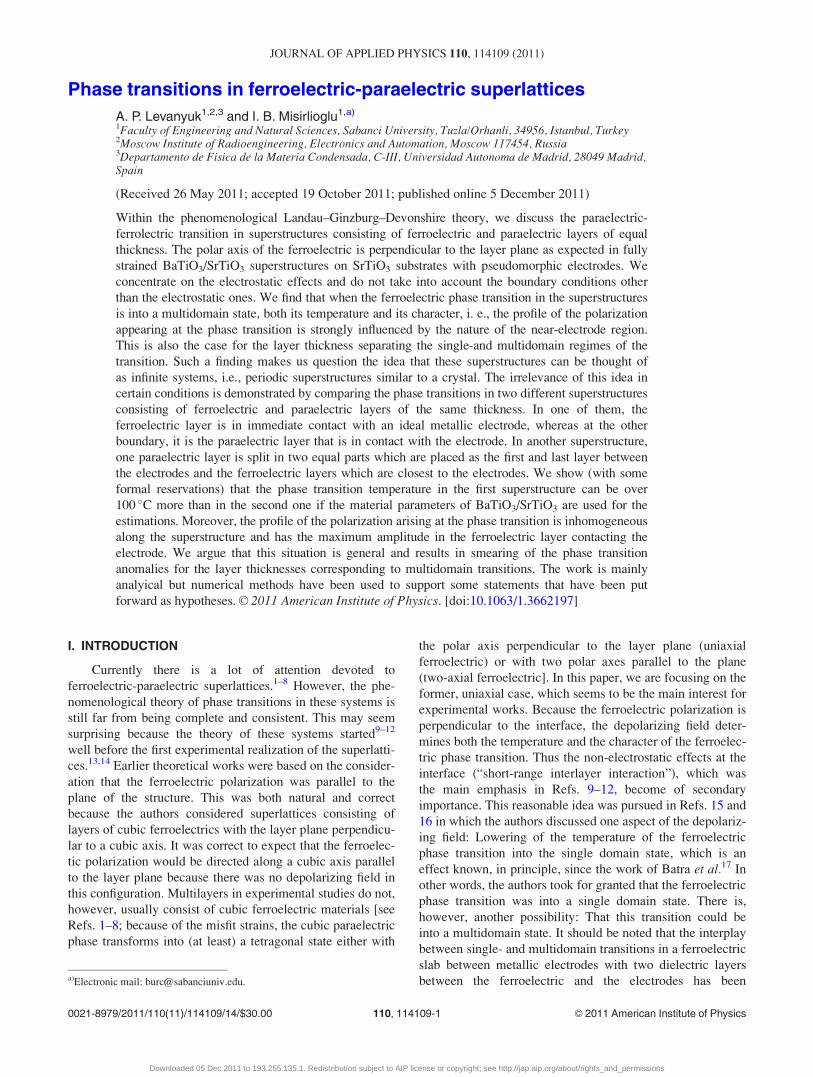
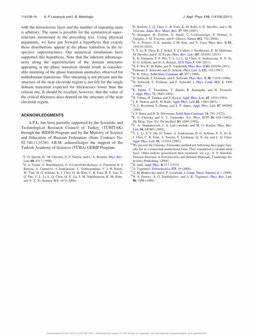
FIG. 13. (Color online) Polarization wave profile at the temperature of
loss of stability of the paraelectric phase in the superstructure consisting of
3 ChT cells, each layer having 8 nm thickness (curve with large period), and
4 ChT cells with each layer being 5 nm thick (curve with small period). Criti-
cal thickness for single domain state stabilization is 4.4 nm. The values used
for BaTiO3 in the calculations are TC¼ 998 �C, Curie constant¼ 1.5� 105 �C,
g¼ 6.2� 10�10 m3/F, and e? ¼ 20, ep¼ 300 for SrTiO3 and for the sake of
convenience is assumed to be constant over the entire temperature range.
114109-11 A. P. Levanyuk and I. B. Misirlioglu J. Appl. Phys. 110, 114109 (2011)
Downloaded 05 Dec 2011 to 193.255.135.1. Redistribution subject to AIP license or copyright; see http://jap.aip.org/about/rights_and_permissions
the ferroelectric polarization appearing at the phase transi-
tion is not periodic along the superstructure if the phase tran-
sition is into a multidomain state. This makes the number of
different types of the polarization profiles with respect to
which the nonpolar phase loses its stability comparable with
the number of unit cells in a given superstructure. We were
able to perform an exhaustive analysis of the loss of stability
of the nonpolar phase only in the two smallest “super-
structures” consisting of two bilayers or two ChT cells. We
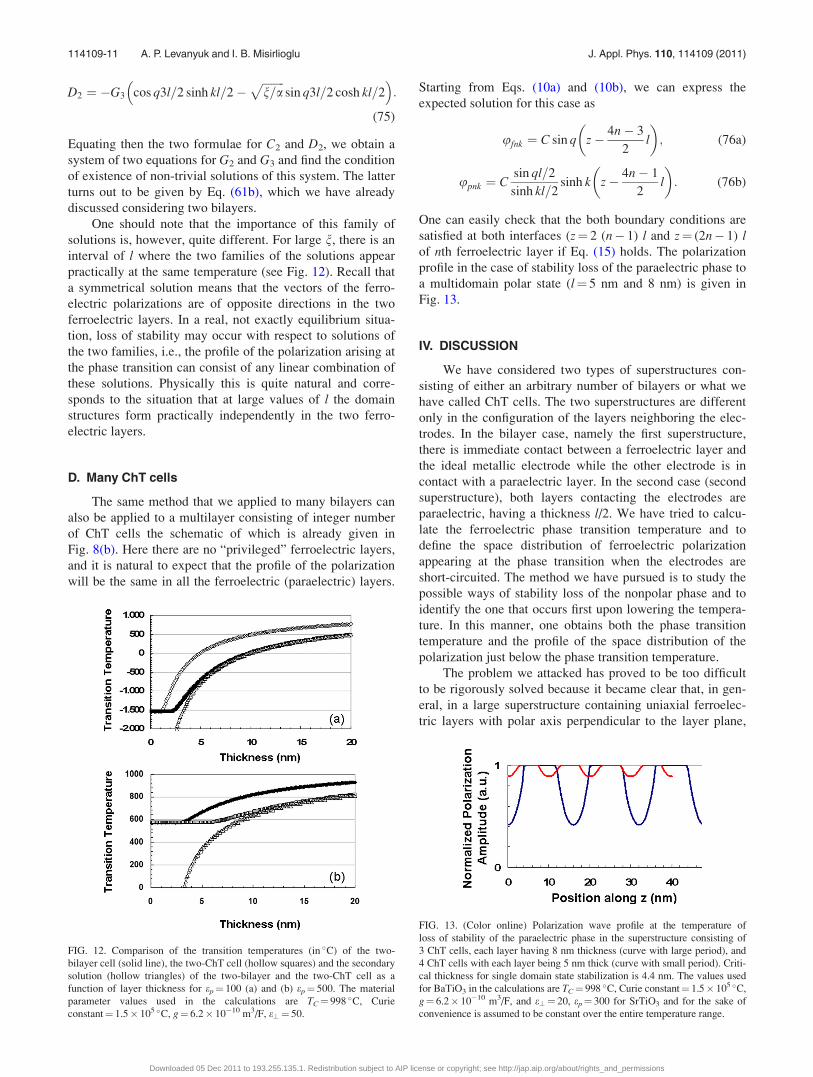
found two families of stability loss for every “small super-
structure.” A comparison of these families of solutions is
presented in Fig. 12. We have also shown that one of the
solution families for both systems, specifically, those that
correspond to the phase transitions in two-bilayer or in two-
ChT cell systems is present in systems of any number of
bilayers or ChT cells. We cannot prove mathematically that
these families of the stability loss correspond to the phase
transitions in very large superstructures as well, but we find
this feasible physically and we assume this as a hypothesis.
Therefore, when we mention “phase transition” in a super-
structure we mean, strictly speaking, a hypothetical phase
transition, which is also supported by our numerical simula-
tions (see Fig. 14).
We found that if the dielectric constant of the paraelec-
tric layer, ep, is larger than e?, there is an interval of ls for
which the ferroelectric phase transition is into a single do-
main state. This interval goes from formally zero l (physi-
cally, of course, not less than unit cell distance) to some lthat can be considerably larger than the unit cell size if ep is
sufficiently large. We focused our attention on this case,
where our continuous medium approach is well justified.
The maximum l that corresponds to the single domain re-
gime we call lc. Importantly, the value of lc for the second
superstructure (lc2) is two times that for the first one
(lc2¼ 2lc1). The physical reason for this is that in the first
superstructure consisting of bilayers, the ferroelectric layer
in immediate contact with the electrode is in a favorable
position for formation of the domain structure: A part of the
stray electric field associated with this structure is removed
by the electrode. This is why for l> lc1, the phase transition
temperature in the first superstucture is higher than in the
second one with the same material parameters and period of
the superstructure. The difference in the phase transition
temperatures can be considerable. For the superstructure
with the parameters of BaTiO3 � SrTiO3 system, this differ-
ence can be nearly 100 �C (see Fig. 7). Also note that the
phase transition temperature in either superstructure does not
depend on the number of unit cells comprising the super-
structure and is the same as the phase transition temperature
for a single bilayer or a single ChT cell.
Spectacularly, the polarization profile in the first super-
structure (consisting of bilayers) is very different from that
of the second superstructure (consisting of ChT cells) as
shown in Figs. 10 and 13. We see that it is incorrect to
assume periodicity along the out-of-plane direction of the
superstructure if this is the superstructure consisting of what
we call the bilayer cells. For the second superstructure, this
is possible, but this superstructure is very specific because it
is symmetric. The cause of the periodic nature of the profile
is this symmetry not the large number of the unit cells in the
superstructure. The first superstructure is not symmetric and
this is also the case for any real superstructure. In Sec. II, we
considered, as an example, a nonsymmetrical trilayer where
the thickness of a paraelectric layer neighboring one of the
electrodes is less than l/2 and the other paraelectric layer
neighboring the opposite electrode is thicker than l/2 with
the total thickness of these layers being l. We have seen that
the maximum value of l corresponding to the phase transition
into a single domain structure (lcn) falls between lc1 and lc2.
It proved to be algebraically too laborious to consider even a
structure of two nonsymmetrical trilayers not to mention
larger structures. It is of little doubt, however, that a super-
structure the paraelectric layers of which contacting the elec-
trodes with thickness different from l/2 behaves qualitatively
similarly to the first superstructure, i.e., the profile of the
polarization arising at the phase transition is not periodic
along the superstructure. To be fair, we should also mention
that at sufficiently large l the lack of symmetry becomes
FIG. 14. (Color online) Polarization maps obtained in our numerical simulations 5 �C below the phase transition for the BaTiO3-SrTiO3 system strained on a
thick electroded SrTiO3 substrate consisting of (a) 8 ChT cells and (b) 8 bilayers with each system having 80 nm total thickness. The system in (a) has a phase
transition temperature around 300 �C and the one in (b) 440 �C, which agrees well with analytical results. The perpendicular colorbar scales are for normalized
polarization. The values used for BaTiO3 in the calculations are TC¼ 998 �C, Curie Constant¼ 1.5 � 105 �C, g¼ 6.2� 10�10 m3/F, e? ¼ 20, ep¼ 300 for
SrTiO3 and for the sake of convenience is assumed to be constant over the entire temperature range.
114109-12 A. P. Levanyuk and I. B. Misirlioglu J. Appl. Phys. 110, 114109 (2011)
Downloaded 05 Dec 2011 to 193.255.135.1. Redistribution subject to AIP license or copyright; see http://jap.aip.org/about/rights_and_permissions
unimportant and the phase transition in a nonsymmetrical tri-
layer is quite similar to that in the symmetrical ChT cell.
This is quite natural and physically means that, at large l, for-
mation of the domain structure in the ferroelectric layers pro-
ceeds similarly to what occurs in a ferroelectric layer in an
infinite paraelectric medium. Clearly, the same phenomenon
is expected in superstructures with large ls where the neigh-
boring ferroelectric layers “do not feel each other” because
intermediate paraelectric layers are too thick. Everything
that we are discussing in this paper is of some real interest
for superstructures with small ls. Here we mean the ls that
are not very different from lc for a given superstructure,
which has to be calculated, of course, with a proper account
of all its specific features. These features include the non-
electrostatic effects at the interfaces and the configuration of
the near electrode region. The latter is what is emphasized in
this paper.
We should emphasize that the focus of our analysis in
the preceding text is on multidomain phase transitions. For
single domain states, however, the situation is quite different.
As an example, consider a hypothetical single domain transi-
tion in a system with real electrodes. A real electrode can be
modeled as an ideal metallic one with a dielectric “dead
layer” at its surface (see, e.g., Ref. 24). It is easy to show
that these parameters of the electrode do not influence the
phase transition temperature and its other characteristics.
Indeed, consider the superstructure presented in Fig. 15.
Because the electric displacement is the same through the
superstructure, one can see that the electric field is the same
(Ef) in all the ferroelectric layers and it is also the same (Ep)
in all the paraelectric ones. Therefore we have
� jef jEf ¼ epEp ¼ eeEd: (77)
The condition of the short-circuiting reads:
Edd þ Nlf Ef þ NlpEp ¼ 0: (78)
This system of three linear equations has non-trivial solu-
tions (point of the stabilitity loss of the paraelectric phase) if
ef ¼ �lf ep
lp 1þ dep
Nee
� � ’ lf ep
lp: (79)
For sufficiently large N, the last approximate equality is
almost exact even for very poor electrodes, i.e., those with
large d and small ee. Physically, this means that even the
presence or absence of the electrodes is not important for the
phase transition into a single domain state.
But to define conditions for a single domain transition
and to find the temperature and other characteristics of a
phase transition into a multidomain state, one has to take
into account the parameters of the electrodes as our paper
convincingly shows. This is not, unfortunately, an easy task
in realistic cases. It is also natural to expect that the differ-
ence between the first and second superstructures will be less
dramatic than we have found in this paper if these super-
structures are supplied with real electrodes. All in all, at the
moment, we do not propose to carry our work further and
take into account the real nature of the electrodes as we think
that this question deserves a separate study.
V. CONCLUSIONS
We considered the phase transition in superstructures
consisting of ferroelectric-paraelectric units having equal
layer thicknesses and the case where the polar axis is perpen-
dicular to the film plane. Our aim was to find the phase tran-
sition temperature and the profile of the polarization
appearing at the transition. To do so, we used the phenome-
nological Landau—Ginzburg–Devonshire theory together
with the equations of electrostatics. The effects of non-
electrostatic boundary conditions have been neglected. The
approach was general but to illustrate the results we referred
to the BaTiO3–SrTiO3 system. The ferroelectric phase tran-
sition in the superstructures is known to be into a multido-
main state if the thickness of the layers is larger than a
certain (“critical”) thickness. For such transitions, we
showed that the transition temperature and domain structures
appearing at the transition are very sensitive to the nature of
the near-electrode regions. Specifically, whether electrodes
are in contact with the ferroelectric layers or not has a promi-
nent impact on these characteristics as well as on the value
of the critical thickness. Moreover, the typical situation
proved to be that the amplitude of the appearing polarization
“waves” in the plane of a given layer is a function of the
layer position with respect to the electrodes. This is irrespec-
tive of the number of the units in the superstructure and,
therefore, the usual assumption about periodicity in super-
structures with sufficiently large number of units is not justi-
fied. The periodicity is possible in a special case only when
the near-electrode layers are paraelectric with half layer
thickness. This is once again valid irrespective of the number
of the units and is connected with a symmetry that the whole
structure has in this case. There are many types of inhomoge-
neous polarization distributions that should in principle be
considered as candidates for the polarization distribution
appearing at the phase transition. It proves unfeasible to find
all these distributions even for systems with a small number
of units, not to mention the general case. We were, however,
able to find a type of polarization distribution that should be
considered as the strongest candidate for the polarization at
the transition if one of the electrodes is in direct contact
FIG. 15. (Color online) Schematic of a superstructure with real electrodes
(denoted by the presence of dead layers at the oxide-electrode interfaces).
The electric field in the paraelectric (EP) and in the ferroelectric (EF) are in
opposite directions to satisfy D¼ constant in the system.
114109-13 A. P. Levanyuk and I. B. Misirlioglu J. Appl. Phys. 110, 114109 (2011)
Downloaded 05 Dec 2011 to 193.255.135.1. Redistribution subject to AIP license or copyright; see http://jap.aip.org/about/rights_and_permissions
with the ferroelectric layer and the number of repeating units
is arbitrary. The same is possible for the symmetrical super-
structure mentioned in the preceding text. Using physical
arguments, we have put forward a hypothesis that exactly
these distributions appear at the phase transition in the re-
spective superstructures. Our numerical simulations have
supported this hypothesis. Note that the inherent inhomoge-
neity along the superstructure of the domain structures
appearing at the phase transition should result in consider-
able smearing of the phase transition anomalies observed for
multidomain transitions. This smearing is not present and the
structure of the near electrode region is not felt for the single
domain transition expected for thicknesses lower than the
critical one. It should be recalled, however, that the value of
the critical thickness does depend on the structure of the near
electrode region.
ACKNOWLEDGMENTS
A.P.L. has been partially supported by the Scientific and
Technological Research Council of Turkey (TUB_ITAK)
through the B_IDEB Program and by the Ministry of Science
and Education of Russian Federation (State Contract No.
02.740.11.5156). I.B.M. acknowledges the support of the
Turkish Academy of Sciences (TUBA) GEB_IP Program.
1E. D. Specht, H. -M. Christen, D. P. Norton, and L. A. Boatner, Phys. Rev.
Lett. 80, 4317 (1998).2D. A. Tenne, A. Bruchhausen, N. D Lanzillotti-Kimura, A. Fainstein, R. S
Katiyar, A. Cantarero, A Soukiassian, V. Vaithyanathan, V. J. H. Haeni,
W. Tian, D. G. Schlom, K. J. Choi, D. M. Kim, C. B. Eom, H. P. Sun, X.
Q. Pan, Y. L. Li, L. Q. Chen, Q. X. Jia, S. M. Nakhmanson, K. M. Rabe,
and X. X. Xi, Science 313, 1614 (2006).
3D. Schlom, L. Q. Chen, C.-B. Eom, K. M. Rabe, S. K. Streiffer, and J.-M.
Triscone, Annu. Rev. Mater. Res. 37, 589 (2007).4E. Bousquet, M. Dawber, N. Stucki, C. Lichtensteiger, P. Hermet, S.
Gariglio, J.-M. Triscone, and P. Ghosez, Nature 452, 732 (2008).5N. A. Pertsev, P.-E. Janolin, J.-M. Kiat, and Y. Uesu, Phys. Rev. B 81,
144118 (2010).6J. Y. Jo, P. Chen, R. J. Sichel, S. J. Callori, J. Sinsheimer, E. M. Dufresne,
M. Dawber, and P. G. Evans, Phys. Rev. Lett. 107, 055501 (2011).7K. K. Galipeau, P. P. Wu, Y. L. Li, L. Q. Chen, A. Soukiassian, X. X. Xi,
D. G. Schlom, and D. A. Bonnel, ACS Nano 5, 640 (2011).8X. F. Wu, K. M. Rabe, and D. Vanderbilt, Phys. Rev. B 83, 020104 (2011).9Fishman, F. Schwabl, and D. Schenk, Phys. Lett. A 121, 192 (1987).
10D. R. Tilley, Solid State Commun. 65, 657 (1988).11D. Schwenk, F. Fishman, and F. Schwabl, Phys. Rev. B 38, 11618 (1988).12D. Schwenk, F. Fishman, and F. Schwabl, J. Phys. Cond. Mat. 2, 5409
(1990).13K. Iijima, T. Terashima, Y. Bando, K. Kamigaki, and H. Terauchi,
J. Appl. Phys. 72, 2840 (1992).14H. Tabata, H. Tanaka, and T. Kawai, Appl. Phys. Lett. 65, 1970 (1994).15J. B. Neaton and K. M. Rabe, Appl. Phys. Lett. 82, 1586 (2003).16A. L. Roytburd, S. Zhong, and S. P. Alpay, Appl. Phys. Lett. 87, 092902
(2005).17I. P. Batra and B. D. Silverman, Solid State Commun. 11, 291 (1972).18E. V. Chensky and V. V. Tarasenko, Sov. Phys. JETP 56, 618 (1982);
Zh. Eksp. Teor. Fiz. Pis’ma Red. 83, 1089 (1982).19V. A. Stephanovich, I. A. Luk’yanchuk, and M. G. Karkut, Phys. Rev.
Lett. 94, 047601 (2005).20Y. L. Li, S. Y. Hu, D. Tenne, A. Soukiassian, D. G. Schlom, X. X. Xi, K.
J. Choi, C. B. Eom, A. Saxena, T. Lookman, Q. X. Jia, and L. Q. Chen,
Appl. Phys. Lett. 91, 112914 (2007).21We present the Chensky–Tarasenko method not following their paper liter-
ally but in a somewhat modernized form. They considered a vacuum dead
layer. Other authors generalized their treatment, see e.g., A. S. Sidorkin,
Domain Structure in Ferroelectrics and Related Materials, Cambridge Int.
Science Publishing, (2006).22H. Suhl, Appl. Phys. 8, 217 (1975).23A. Tagantsev, Ferroelectrics 375, 19 (2008).24A. M. Bratkovsky and A. P. Levanyuk, J. Comp. Theor. Nanosci. 6, 1 (2009).25N. A. Pertsev, A. G. Zembilgotov, and A. K. Tagantsev, Phys. Rev. Lett.
80, 1988 (1998).
114109-14 A. P. Levanyuk and I. B. Misirlioglu J. Appl. Phys. 110, 114109 (2011)
Downloaded 05 Dec 2011 to 193.255.135.1. Redistribution subject to AIP license or copyright; see http://jap.aip.org/about/rights_and_permissions