Page 1
University of San DiegoDigital USD
Undergraduate Honors Theses Theses and Dissertations
Fall 12-19-2016
Phased Helical Antenna Array for CubeSatApplicationKameron LaCalliklacalli
Follow this and additional works at: http://digital.sandiego.edu/honors_theses
Part of the Electrical and Electronics Commons, Space Vehicles Commons, and the SystemsEngineering Commons
This Undergraduate Honors Thesis is brought to you for free and open access by the Theses and Dissertations at Digital USD. It has been accepted forinclusion in Undergraduate Honors Theses by an authorized administrator of Digital USD. For more information, please contact [email protected] .
Digital USD CitationLaCalli, Kameron, "Phased Helical Antenna Array for CubeSat Application" (2016). Undergraduate Honors Theses. 32.http://digital.sandiego.edu/honors_theses/32
Page 2
Phased Helical Antenna Array for CubeSat Application
______________________
A Thesis
Presented to
The Faculty and the Honors Program
Of the University of San Diego
______________________
By
Kameron James LaCalli
Electrical Engineering
2016
Page 3
1
Preface
This design is presented as completion of the Honors Program at University of San Diego under
advisorship of Dr. Kathleen Kramer and Dr. James Gilb. The work here, while done individually,
is done as contribution to the University of San Diego CubeSat Team, established in 2016, in
hopes of advancing CubeSat communications technology while still considering cost restraints.
The scope of this thesis only goes as far as a design, and due to time restrictions does not delve
into hardware development or physical testing. Focus will also primarily be on the RF (radio
frequency) elements of the phased array system, as there is much to be designed still constitute a
fully functioning space-ready CubeSat design.
Page 4
2
Contents Introduction ................................................................................................................................................... 4
Background ................................................................................................................................................... 4
CubeSats ................................................................................................................................................... 4
Phased Arrays ........................................................................................................................................... 5
General Design .............................................................................................................................................. 6
Limitations & Considerations ................................................................................................................... 6
Primary Concept ....................................................................................................................................... 7
Frequency & Protocol ........................................................................................................................... 8
Antenna ................................................................................................................................................. 8
Part Selection & Description..................................................................................................................... 9
CubeSat Parts ........................................................................................................................................ 9
Ground Station Parts ........................................................................................................................... 10
Power Budget ...................................................................................................................................... 10
RF Design ................................................................................................................................................... 11
Link Budget ............................................................................................................................................ 11
Losses .................................................................................................................................................. 12
Gains ................................................................................................................................................... 13
Summary ............................................................................................................................................. 13
Antenna Design ....................................................................................................................................... 14
Phased Array Modeling .......................................................................................................................... 16
Antenna Model .................................................................................................................................... 16
Array Model ........................................................................................................................................ 18
Wilkinson Power Divider ....................................................................................................................... 20
Conclusion .................................................................................................................................................. 24
Summary and Future Work ................................................................................................................. 24
Thanks ................................................................................................................................................. 25
Appendix ..................................................................................................................................................... 26
Supplementary Figures ........................................................................................................................... 26
References ............................................................................................................................................... 28
Page 5
3
List of Figures
Figure 1: Block Diagram of Overall Design ................................................................................... 7
Figure 2: Physical Layout ............................................................................................................... 8
Figure 3: Free Space Path Loss Illustration and Equation ............................................................ 12
Figure 4: Helical Antenna Design Equations and Physical Specifications ................................... 15
Figure 5: Scale Layout of Helical Antennas ................................................................................. 15
Figure 6: 4NEC2 Antenna Specification Page .............................................................................. 16
Figure 7: Polar Pattern from 4NEC2 Helical Antenna ................................................................. 17
Figure 8: 4NEC2 3D Model of Helical Antenna Radiation .......................................................... 17
Figure 9: Comparison of 4NEC2 Model and Matlab Immitation, Note Scale Differences .......... 18
Figure 10: Array Factor Equation ................................................................................................. 19
Figure 11: Array Factor Value at Various Degree Shifts ............................................................. 20
Figure 12: Final Phased Model with -40, 0, and 40 Degree Shifts ............................................... 20
Figure 13: Wilkinson Power Divider Design Specification ......................................................... 21
Figure 14: Lumped Element Divider Equivalent Schematic ........................................................ 22
Figure 15: 1 to 4 Wilkinson Microstrip ADS Design ................................................................... 22
Figure 16: S Paramters for Microstrip Design .............................................................................. 23
Figure 17: Microstrip Design Board Layout ................................................................................. 23
Figure 18:Example of Matlab Script for Phased Array Calculation ............................................. 26
Figure 19:Lumped Element LC Design in ADS ........................................................................... 26
Figure 20: S Parameters of LC Design ......................................................................................... 27
List of Tables
Table 1: Power Budget.................................................................................................................. 11
Table 2: Link Budget at 1000km .................................................................................................. 13
Table 3: Link Budget at 200km .................................................................................................... 14
Page 6
4
Introduction
Due to their size, CubeSats and other small satellites are severely limited in power and
communication capabilities. Small, sometimes non deployable solar panels restrict potential
transmission power, and physical layout limits space for higher gain antenna configurations, such
as parabolic dishes, reflective arrays, and horn antennas. These restrictions have had the
tendency to force CubeSat missions to have slower communications speeds, limiting the amount
of data that can be transferred per overhead pass. So far this limitation hasn’t been severely
restraining on missions, as smaller CubeSats typically acquire a relatively small amount of data
with only a few sensors. However, higher downlink speeds would allow for more data collection
as sensors continue to be manufactured smaller and cheaper, squeezing more capability into the
1000 cm2 CubeSat frame. A higher throughput standard for CubeSats would also allow for
innovative approaches to satellite networking and beyond low earth orbit capabilities.
The purposes of this study are to investigate and design the RF components of a phased array
antenna for 1U CubeSat application, to establish the feasibility of higher speed, lower power,
low cost CubeSat communication capabilities.
Background
CubeSats
CubeSats, a standardized form factor for small satellites, are rapidly disrupting the satellite
business. In the 1980’s and 1990’s, common research or surveillance satellites were large, heavy,
and required long term projects that cost tens or even hundreds of millions of dollars. As such,
designers ensured that these satellites would perform hundreds of tasks and have lifespans
upwards of 10+ years. Recent technologies however are allowing governments, businesses, and
universities to accomplish similar goals with cheap, lightweight, low power, electronics due
Page 7
5
largely in part to the recent surge of smartphone components. With computing power similar to
the processor found in a smartphone, small satellites can perform specific missions at a fraction
of the cost and timeframe. They may not be quite as capable as older larger satellites, but they
cost only tens or hundreds of thousands of dollars, and can be developed and launched
exponentially faster.
In an effort to bring the smallsat cost down even further, the CubeSat specification was
developed by a partnership between California Polytechnic University and Stanford University
in 1999, with the first successful mission in 2003 [8]. This specification defines a physical
standard for small satellites to adhere to, allowing companies to mass produce sub systems for
the satellite that any payload can easily integrate to (otherwise, a “design from scratch” approach
is required for all subsystems). This also simplifies the launch process, as anyone can design
around the CubeSat standard and know with certainty that it will integrate into and deploy
properly from the launch system, as previously, satellites required complicated custom
integration.
Phased Arrays
The other primary technical field this thesis delves into is phased array antenna technology. First
conceptualized in 1905 by Nobel laureate Karl Braun [6], phased array antenna radios use
multiple antennas in conjunction, varying the phase of each antenna’s signal to get the
propagation patterns of each to constructively interfere with each other in certain directions and
deconstructively interfere in others [7]. This creates a stronger signal at specific angles to the
antenna, allowing the radio to “target” where it sends the majority of its power, resulting in
further, clearer, higher speed transmission. Commonly used in military and radar applications,
phased arrays are seldom deployed in space applications, much less smallsats/CubeSats (though
Page 8
6
designs exist, documentation on deployed phased antenna is scarce) [2]. The 2011 launched
Messenger spacecraft is an early documented space-based application of a phased-array system.
This field encompasses a large number of classified missions, as well, where there are a
significant number of projects with documentation that is not publically available [12].
General Design
Limitations & Considerations
Being designed around a single unit CubeSat, space and power are severely limited. When
designing a phased array, the number of elements is critical to its successful operation and beam
forming capabilities. However, with only 1U there isn’t much space for a large array. Deploying
panels after launch and separation can increase effective area (and antenna aperture), though it
quickly increases mechanical complexity as well. Power must also be considered, as typical
CubeSat solar panel configurations only generate a few watts of power [1]. Other subsystems
rely on this power as well, restricting the power available to the transmitter. For purposes of this
design, the payload itself will be the phased array transmitter as a technology demonstration,
allowing more in the power budget for the phased array.
Additionally, reaction wheels can consume considerable amounts of power orienting the satellite,
though with the beam steering capabilities of a phased array physical orientation will be less
critical for successful data connection. Lower power magnetorquers will provide sufficient earth
facing orientation, with the beam steering handling the specific directionality of the high speed
telemetry.
Link frequency must also be chosen carefully, as higher frequency can allow for higher
throughput, though may also be inefficient for long range communication (due free space path
Page 9
7
loss). As one of the primary benefits to a CubeSat is cost, availability of low cost/low volume
parts at this specified frequency will be crucial for design feasibility. Apart from frequency
choice though, lower cost for materials and general components will be important to keep with
CubeSat convention.
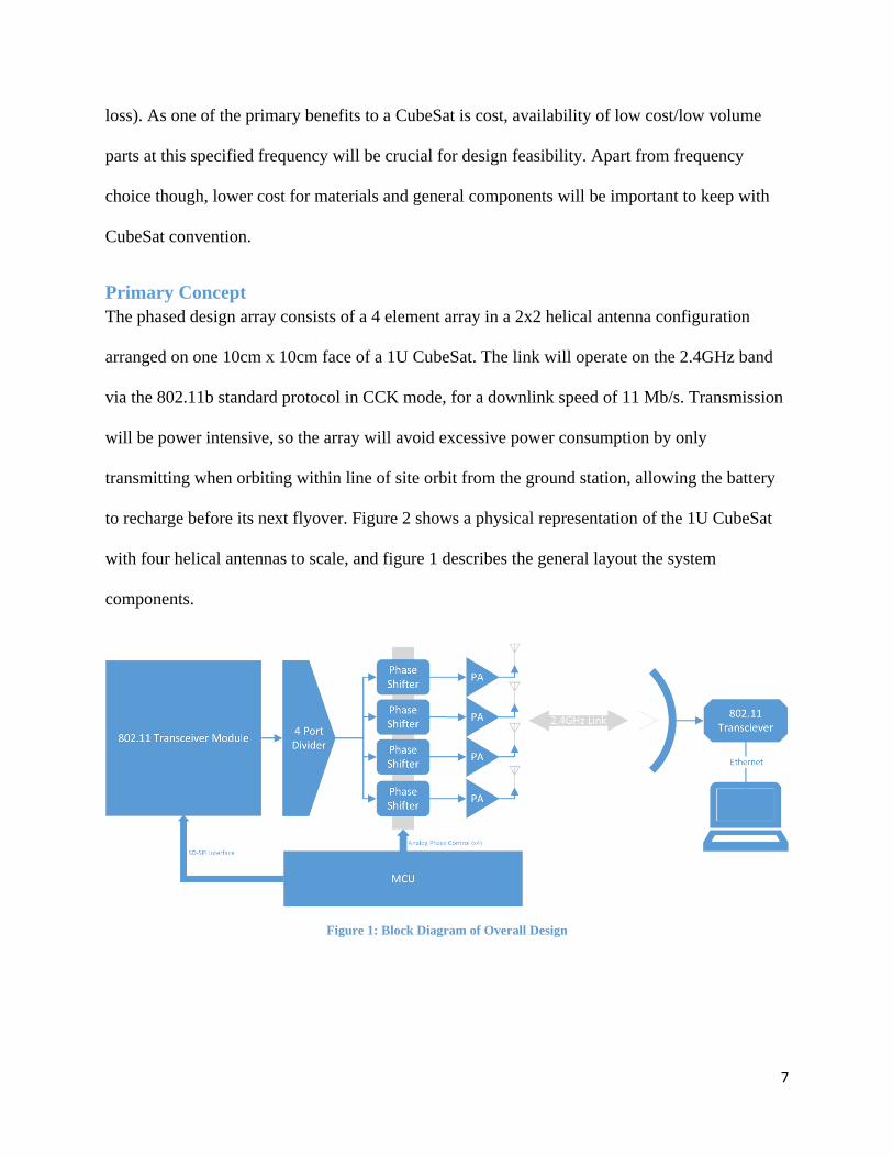
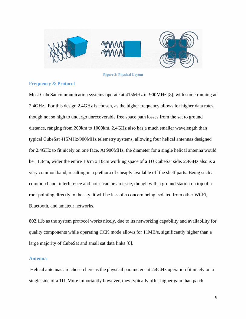
Primary Concept
The phased design array consists of a 4 element array in a 2x2 helical antenna configuration
arranged on one 10cm x 10cm face of a 1U CubeSat. The link will operate on the 2.4GHz band
via the 802.11b standard protocol in CCK mode, for a downlink speed of 11 Mb/s. Transmission
will be power intensive, so the array will avoid excessive power consumption by only
transmitting when orbiting within line of site orbit from the ground station, allowing the battery
to recharge before its next flyover. Figure 2 shows a physical representation of the 1U CubeSat
with four helical antennas to scale, and figure 1 describes the general layout the system
components.
Figure 1: Block Diagram of Overall Design
Page 10
8
Figure 2: Physical Layout
Frequency & Protocol
Most CubeSat communication systems operate at 415MHz or 900MHz [8], with some running at
2.4GHz. For this design 2.4GHz is chosen, as the higher frequency allows for higher data rates,
though not so high to undergo unrecoverable free space path losses from the sat to ground
distance, ranging from 200km to 1000km. 2.4GHz also has a much smaller wavelength than
typical CubeSat 415MHz/900MHz telemetry systems, allowing four helical antennas designed
for 2.4GHz to fit nicely on one face. At 900MHz, the diameter for a single helical antenna would
be 11.3cm, wider the entire 10cm x 10cm working space of a 1U CubeSat side. 2.4GHz also is a
very common band, resulting in a plethora of cheaply available off the shelf parts. Being such a
common band, interference and noise can be an issue, though with a ground station on top of a
roof pointing directly to the sky, it will be less of a concern being isolated from other Wi-Fi,
Bluetooth, and amateur networks.
802.11b as the system protocol works nicely, due to its networking capability and availability for
quality components while operating CCK mode allows for 11MB/s, significantly higher than a
large majority of CubeSat and small sat data links [8].
Antenna
Helical antennas are chosen here as the physical parameters at 2.4GHz operation fit nicely on a
single side of a 1U. More importantly however, they typically offer higher gain than patch
Page 11
9
antennas (commonly used in phased array configurations), ensuring a link connection with high
data rates. Relatively simple in design and construction, they also offer a sort of “self-deploying”
feature, in that the coil will have spring force capable of uncoiling itself [13]. Mechanical
restriction before deployment may involve nichrome wire to control release of the helical
antennas. More design will need to be done however to perfect the layout and deployment once
in orbit.
Part Selection & Description
Primary active RF components for both the CubeSat and the ground station were chosen
carefully with necessary requirements and power limitations in mind. Non-RF components
(power, MCU, etc.) extend beyond the purposes of this design, as they are heavily dependent on
other subsystems.
CubeSat Parts
Transceiver - The 802.11 capable transceiver needs to be low power and easily interfaced. High
power output is not needed as signal amplification is done later in the path with the power
amplifier, whereas there is actually an upper limit of signal power acceptable by the phase
shifter, so adjustable gain is necessary. CCK mode capability (11Mb/s), though common on
802.11 transceivers is still a necessary trait. The Microchip RN171 LAN module with high speed
SD-SPI interface, same interface used for writing to SD cards satisfies criteria nicely, with only
120mA current draw at 3.3V.
Phase Shifter - The Mini Circuits JSPHS phase shifter is actually one of very few small package,
low power options available for the 2.4GHz band. Less than 2dB insertion loss is plenty low, and
320° phase shift capability is much more than needed.
Page 12
10
Power Amp - For the power amplifier two viable options appear, one being lower power, the
other having satisfactory low power requirements with much higher power output. The
Skyworks SE2568U Wireless LAN PA is designed for the 802.11b standard, and provides up to
20 dBm output, while drawing 528 mW while amplifying. It also is relatively easy to use in only
an 8-pin package. The Qorvo TQP9224 Small Cell PA pulls almost double the power, but is
capable of putting out 24dBm and higher (nonlinear region) in a slightly more complicated 14
pin package. If power budget allows in conjunction with the rest of the CubeSat subsystems, this
option will help ensure link budget completion with its higher gain.
Ground Station Parts
Antenna - The ground antenna on the receiving end of the link needs to have a high gain, and the
L-Com 30dBi steel grid parabola provides just that. Being highly directional, it may require a
mechanically steerable base to “follow” the CubeSat at is orbits across the ski, though the phased
beam steering array on the CubeSat may be able to accommodate for that.
Receiver - Without power or size limitations on a ground station, a condensed and easy to use
package with high sensitivity is the best option for the receiver. Marketed for the somewhat now-
defunct “Wi-Max” venture, the Ubiquiti Bullet M provides a rugged weatherproof transceiver
with Ethernet LAN connection for easy PC integration and highly sensitive -97dBm receive
sensitivity. Software for easy control are included as well, and is available for approximately
$80.00 USD.
Power Budget
An in depth power budget is not needed for this study, as feasibility is the primary concern. As
such, as long as typical 1U CubeSat power capabilities can be adhered to, the system will be
Page 13
11
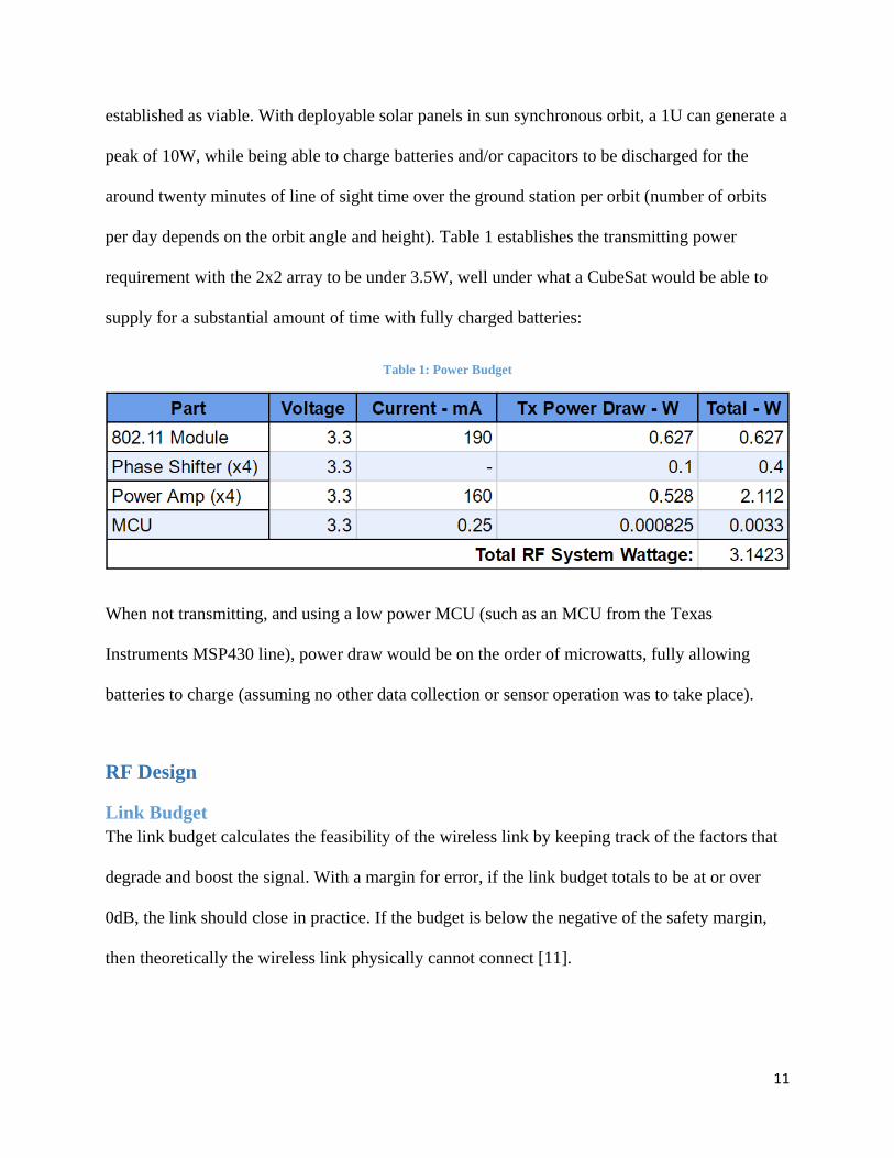
established as viable. With deployable solar panels in sun synchronous orbit, a 1U can generate a
peak of 10W, while being able to charge batteries and/or capacitors to be discharged for the
around twenty minutes of line of sight time over the ground station per orbit (number of orbits
per day depends on the orbit angle and height). Table 1 establishes the transmitting power
requirement with the 2x2 array to be under 3.5W, well under what a CubeSat would be able to
supply for a substantial amount of time with fully charged batteries:
Table 1: Power Budget
When not transmitting, and using a low power MCU (such as an MCU from the Texas
Instruments MSP430 line), power draw would be on the order of microwatts, fully allowing
batteries to charge (assuming no other data collection or sensor operation was to take place).
RF Design
Link Budget
The link budget calculates the feasibility of the wireless link by keeping track of the factors that
degrade and boost the signal. With a margin for error, if the link budget totals to be at or over
0dB, the link should close in practice. If the budget is below the negative of the safety margin,
then theoretically the wireless link physically cannot connect [11].
Page 14
12
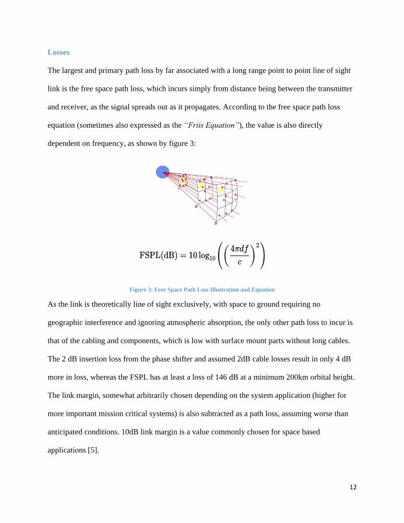
Losses
The largest and primary path loss by far associated with a long range point to point line of sight
link is the free space path loss, which incurs simply from distance being between the transmitter
and receiver, as the signal spreads out as it propagates. According to the free space path loss
equation (sometimes also expressed as the “Friis Equation”), the value is also directly
dependent on frequency, as shown by figure 3:
Figure 3: Free Space Path Loss Illustration and Equation
As the link is theoretically line of sight exclusively, with space to ground requiring no
geographic interference and ignoring atmospheric absorption, the only other path loss to incur is
that of the cabling and components, which is low with surface mount parts without long cables.
The 2 dB insertion loss from the phase shifter and assumed 2dB cable losses result in only 4 dB
more in loss, whereas the FSPL has at least a loss of 146 dB at a minimum 200km orbital height.
The link margin, somewhat arbitrarily chosen depending on the system application (higher for
more important mission critical systems) is also subtracted as a path loss, assuming worse than
anticipated conditions. 10dB link margin is a value commonly chosen for space based
applications [5].
Page 15
13
Gains
On the other end, the antenna gains and both transceiver power and receiver sensitivity provide a
gain in the link budget calculation. Values pulled from the data sheets and antenna design specs
provide for easy summation. The receiver sensitivity is subtracted as a negative number, as the
negative dBm value indicates how small a signal can be for the receiver to still reliably detect it,
and is thus subtracted from the equation resulting in net a positive [4]. This receiver sensitivity at
-97dBm provides the largest value of the link budget gains.
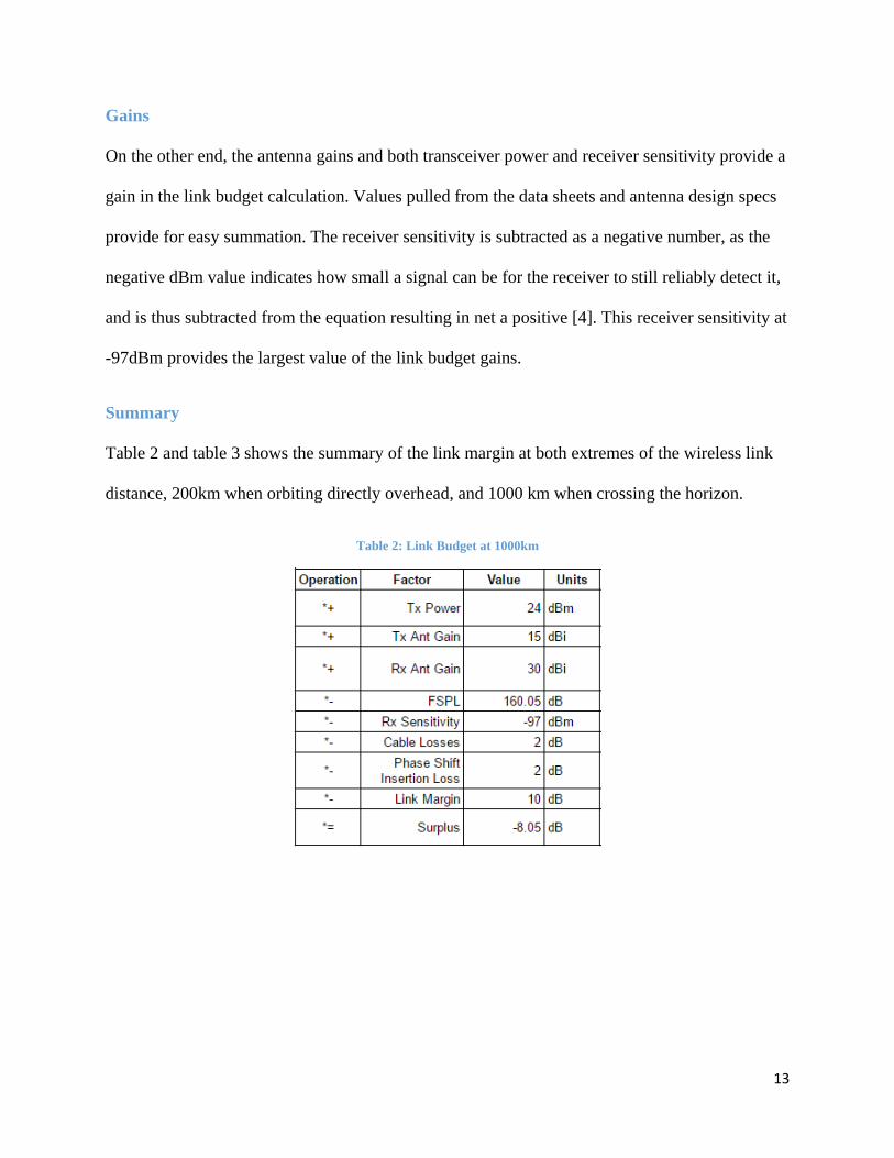
Summary
Table 2 and table 3 shows the summary of the link margin at both extremes of the wireless link
distance, 200km when orbiting directly overhead, and 1000 km when crossing the horizon.
Table 2: Link Budget at 1000km
Page 16
14
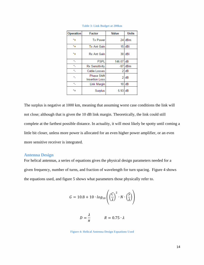
Table 3: Link Budget at 200km
The surplus is negative at 1000 km, meaning that assuming worst case conditions the link will
not close; although that is given the 10 dB link margin. Theoretically, the link could still
complete at the farthest possible distance. In actuality, it will most likely be spotty until coming a
little bit closer, unless more power is allocated for an even higher power amplifier, or an even
more sensitive receiver is integrated.
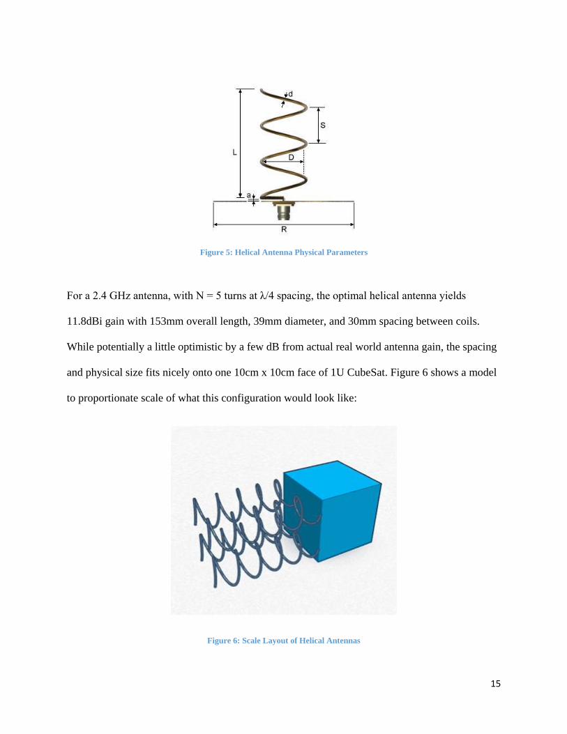
Antenna Design
For helical antennas, a series of equations gives the physical design parameters needed for a
given frequency, number of turns, and fraction of wavelength for turn spacing. Figure 4 shows
the equations used, and figure 5 shows what parameters those physically refer to.
𝐺 = 10.8 + 10 ∙ 𝑙𝑜𝑔10 ((𝐶
𝜆)
2
∙ 𝑁 ∙ (𝑆
𝜆))
𝐷 =𝜆
𝜋 𝑅 = 0.75 ∙ 𝜆
Figure 4: Helical Antenna Design Equations Used
Page 17
15
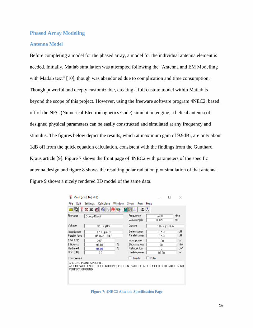
Figure 5: Helical Antenna Physical Parameters
For a 2.4 GHz antenna, with N = 5 turns at λ/4 spacing, the optimal helical antenna yields
11.8dBi gain with 153mm overall length, 39mm diameter, and 30mm spacing between coils.
While potentially a little optimistic by a few dB from actual real world antenna gain, the spacing
and physical size fits nicely onto one 10cm x 10cm face of 1U CubeSat. Figure 6 shows a model
to proportionate scale of what this configuration would look like:
Figure 6: Scale Layout of Helical Antennas
Page 18
16
Phased Array Modeling
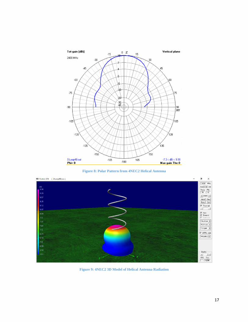
Antenna Model
Before completing a model for the phased array, a model for the individual antenna element is
needed. Initially, Matlab simulation was attempted following the “Antenna and EM Modelling
with Matlab text” [10], though was abandoned due to complication and time consumption.
Though powerful and deeply customizable, creating a full custom model within Matlab is
beyond the scope of this project. However, using the freeware software program 4NEC2, based
off of the NEC (Numerical Electromagnetics Code) simulation engine, a helical antenna of
designed physical parameters can be easily constructed and simulated at any frequency and
stimulus. The figures below depict the results, which at maximum gain of 9.9dBi, are only about
1dB off from the quick equation calculation, consistent with the findings from the Gunthard
Kraus article [9]. Figure 7 shows the front page of 4NEC2 with parameters of the specific
antenna design and figure 8 shows the resulting polar radiation plot simulation of that antenna.
Figure 9 shows a nicely rendered 3D model of the same data.
Figure 7: 4NEC2 Antenna Specification Page
Page 19
17
Figure 8: Polar Pattern from 4NEC2 Helical Antenna
Figure 9: 4NEC2 3D Model of Helical Antenna Radiation
Page 20
18
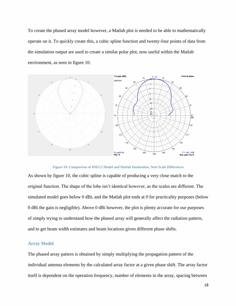
To create the phased array model however, a Matlab plot is needed to be able to mathematically
operate on it. To quickly create this, a cubic spline function and twenty-four points of data from
the simulation output are used to create a similar polar plot, now useful within the Matlab
environment, as seen in figure 10.
Figure 10: Comparison of 4NEC2 Model and Matlab Immitation, Note Scale Differences
As shown by figure 10, the cubic spline is capable of producing a very close match to the
original function. The shape of the lobe isn’t identical however, as the scales are different. The
simulated model goes below 0 dBi, and the Matlab plot ends at 0 for practicality purposes (below
0 dBi the gain is negligible). Above 0 dBi however, the plot is plenty accurate for our purposes
of simply trying to understand how the phased array will generally affect the radiation pattern,
and to get beam width estimates and beam locations given different phase shifts.
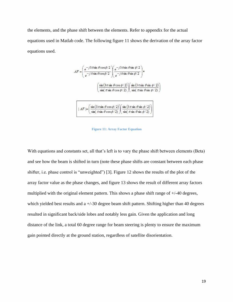
Array Model
The phased array pattern is obtained by simply multiplying the propagation pattern of the
individual antenna elements by the calculated array factor at a given phase shift. The array factor
itself is dependent on the operation frequency, number of elements in the array, spacing between
Page 21
19
the elements, and the phase shift between the elements. Refer to appendix for the actual
equations used in Matlab code. The following figure 11 shows the derivation of the array factor
equations used.
Figure 11: Array Factor Equation
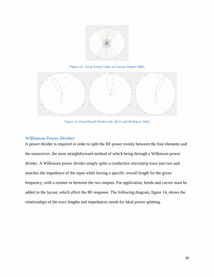
With equations and constants set, all that’s left is to vary the phase shift between elements (Beta)
and see how the beam is shifted in turn (note these phase shifts are constant between each phase
shifter, i.e. phase control is “unweighted”) [3]. Figure 12 shows the results of the plot of the
array factor value as the phase changes, and figure 13 shows the result of different array factors
multiplied with the original element pattern. This shows a phase shift range of +/-40 degrees,
which yielded best results and a +/-30 degree beam shift pattern. Shifting higher than 40 degrees
resulted in significant back/side lobes and notably less gain. Given the application and long
distance of the link, a total 60 degree range for beam steering is plenty to ensure the maximum
gain pointed directly at the ground station, regardless of satellite disorientation.
Page 22
20
Figure 12: Array Factor Value at Various Degree Shifts
Figure 13: Final Phased Model with -40, 0, and 40 Degree Shifts
Wilkinson Power Divider
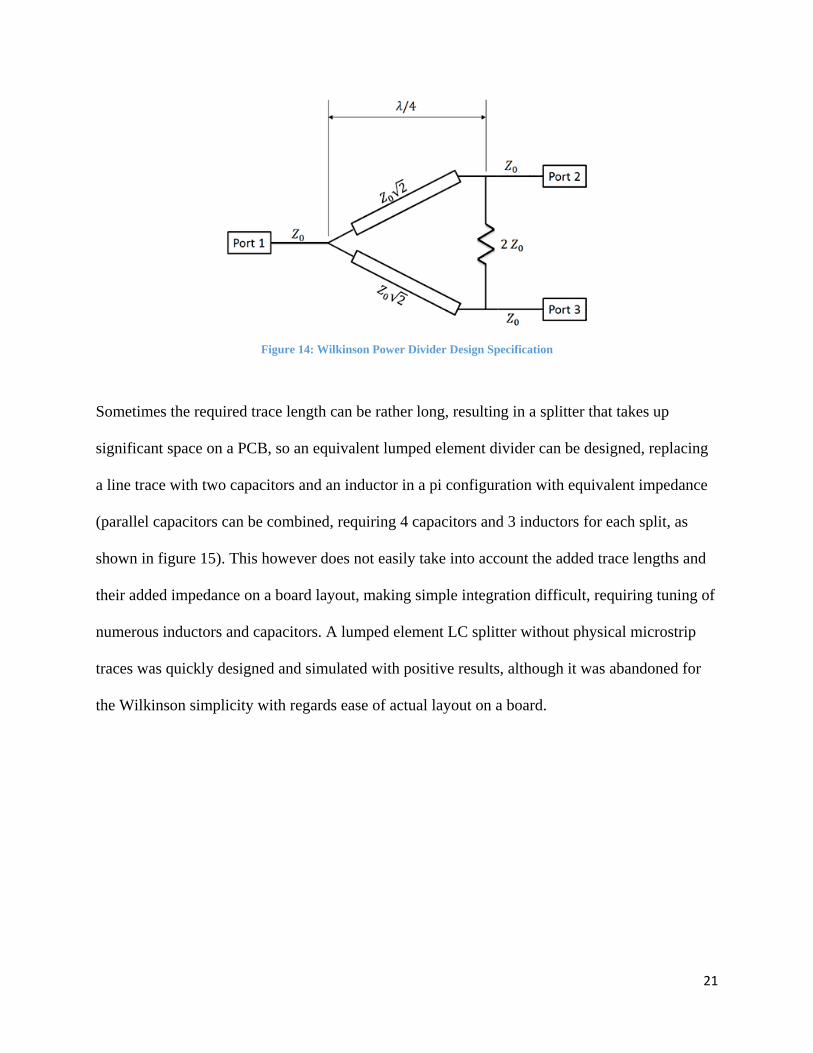
A power divider is required in order to split the RF power evenly between the four elements and
the transceiver, the most straightforward method of which being through a Wilkinson power
divider. A Wilkinson power divider simply splits a conductive microstrip trace into two and
matches the impedance of the input while having a specific overall length for the given
frequency, with a resistor in between the two outputs. For application, bends and curves must be
added to the layout, which affect the RF response. The following diagram, figure 14, shows the
relationships of the trace lengths and impedances needs for ideal power splitting.
Page 23
21
Figure 14: Wilkinson Power Divider Design Specification
Sometimes the required trace length can be rather long, resulting in a splitter that takes up
significant space on a PCB, so an equivalent lumped element divider can be designed, replacing
a line trace with two capacitors and an inductor in a pi configuration with equivalent impedance
(parallel capacitors can be combined, requiring 4 capacitors and 3 inductors for each split, as
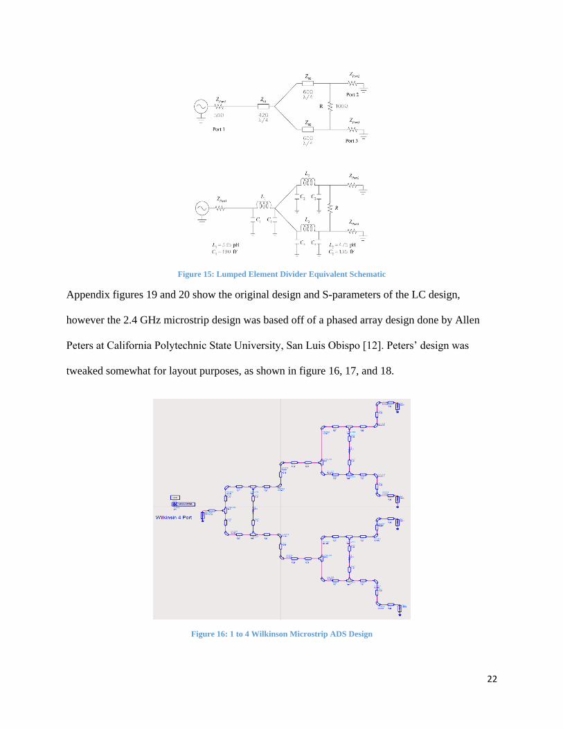
shown in figure 15). This however does not easily take into account the added trace lengths and
their added impedance on a board layout, making simple integration difficult, requiring tuning of
numerous inductors and capacitors. A lumped element LC splitter without physical microstrip
traces was quickly designed and simulated with positive results, although it was abandoned for
the Wilkinson simplicity with regards ease of actual layout on a board.
Page 24
22
Figure 15: Lumped Element Divider Equivalent Schematic
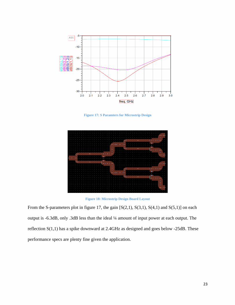
Appendix figures 19 and 20 show the original design and S-parameters of the LC design,
however the 2.4 GHz microstrip design was based off of a phased array design done by Allen
Peters at California Polytechnic State University, San Luis Obispo [12]. Peters’ design was
tweaked somewhat for layout purposes, as shown in figure 16, 17, and 18.
Figure 16: 1 to 4 Wilkinson Microstrip ADS Design
Page 25
23
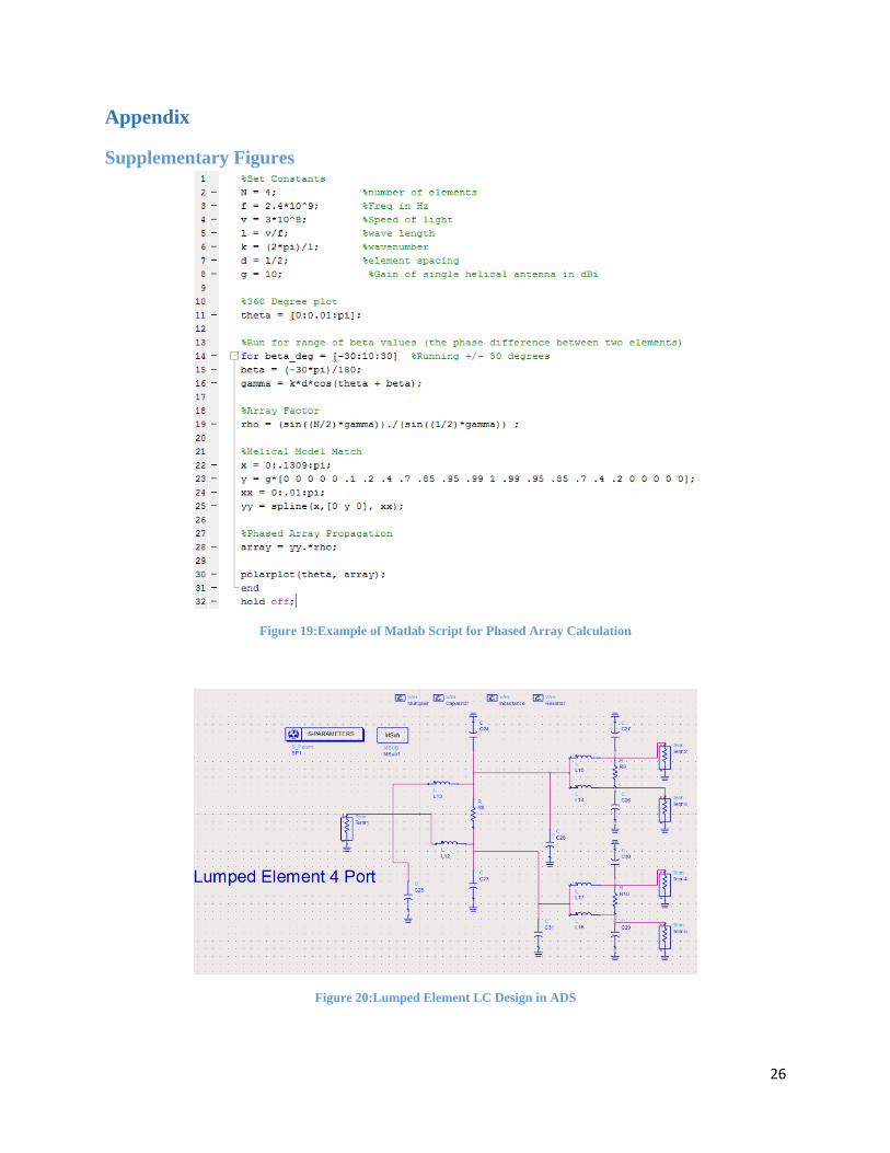
Figure 17: S Paramters for Microstrip Design
Figure 18: Microstrip Design Board Layout
From the S-parameters plot in figure 17, the gain [S(2,1), S(3,1), S(4,1) and S(5,1)] on each
output is -6.3dB, only .3dB less than the ideal ¼ amount of input power at each output. The
reflection S(1,1) has a spike downward at 2.4GHz as designed and goes below -25dB. These
performance specs are plenty fine given the application.
Page 26
24
Conclusion
Summary and Future Work
With the power budget totaling at just a few watts and link budget completion with low power
COTS parts, feasibility of a 4 element phased array downlink communication system has been
confirmed. The system theoretically is capable of sending downlink data faster than any
successfully deployed CubeSat at 11Mb/s [8], and will be able to run on low enough power to
provide power to other subsystems and sensors (though not much, provided there is ample
charging time with deployable solar panels). Aside from the high data rate, phased array
technology itself has not yet been successfully launched on a CubeSat (though there are designs
and work towards it), and potentially may have never been done on a small sat in general, being
that there is little documentation on space based phased arrays. Hopefully the work presented
here contributes to that push forward in small satellite communications technology.
Being only a theoretical thesis design, physical hardware testing obviously still needs to take
place to further confirm the feasibility of an 11Mb/s phased array CubeSat system. Even before
that, is still design work to be done, as this study focused only on the RF components needed.
With regards to the communication system, MCU control of the phase shifters, as well as MCU
interfacing to the transceiver, though not overtly complex, still requires work. An entire
schematic and board layout for all components selected is needed as well, with power supply
power, to simply run a connection test. From there mechanical and electrical integration with an
entire CubeSat bus will provide a fully working standalone system with the ground station.
Page 27
25
Thanks
I would like to thank Dr. Kathleen Kramer and Dr. James Gilb in the Electrical Engineering
Department at the University of San Diego for their help with this study, and for the extra time
they put in to help my project along. I would also like to thank the Honors Department at USD,
run by Dr. James Gump and Erin Prickett, for providing the Honors Thesis infrastructure, as well
as organizing the wonderful Honors classes I have taken over the course of my undergraduate
education.
Page 28
26
Appendix
Supplementary Figures
Figure 19:Example of Matlab Script for Phased Array Calculation
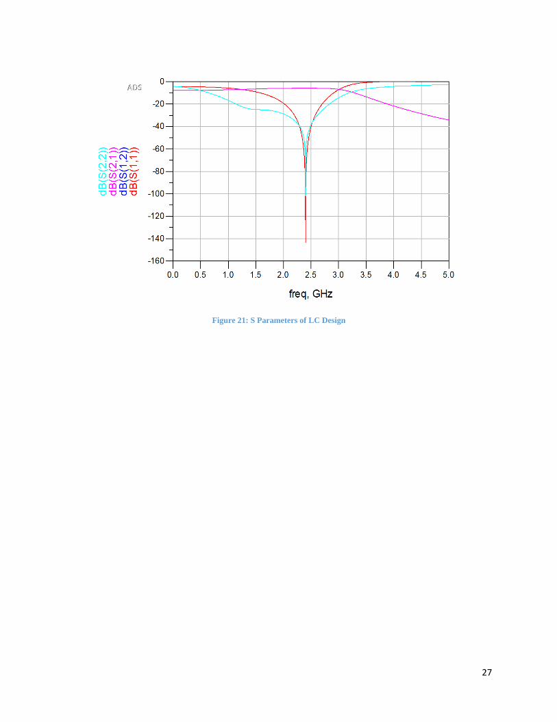
Figure 20:Lumped Element LC Design in ADS
Page 29
27
Figure 21: S Parameters of LC Design
Page 30
28
References
[1] Aragón, V., García, Á, Amaro, R., Martínez, C., & Sarmiento, F. (2011).Researching a
Robust Communication Link for CubeSats: OPTOS, a new Approach(Unpublished master's
thesis). National Institute of Aerospace Technology. Retrieved November 2, 2016, from
https://www.thinkmind.org/index.php?view=article&articleid=spacomm_2011_3_20_30059
[2] Balanis, C. A. (1997).Antenna Theory: Analysis and Design(2nd ed.). Hoboken, NJ: John
Wiley & Sons.
[3] Bevelacqua, P. J. (n.d.). Antenna Arrays. Retrieved October 5, 2016, from
http://www.antenna-theory.com/arrays/main.php
[4] Cantero Gómez, J. (2013).Communication link design at 437.5 MHz for a
nanosatellite(Unpublished master's thesis). Aalto University. Retrieved November 2, 2016, from
https://aaltodoc.aalto.fi/handle/123456789/11119
[5] Capela, C. (2012).Protocol of Communications for VORSAT Satellite - Link
Budget(Unpublished master's thesis). University of Porto. Retrieved September 15, 2016, from
http://paginas.fe.up.pt/~ee97054/Link%20Budget.pdf
[6] Dang, K. (2016).Phased Array Antenna Investigation for CubeSat Size
Satellites(Unpublished master's thesis). Morehead State University. Retrieved September 15,
2016, from
http://scholarworks.moreheadstate.edu/cgi/viewcontent.cgi?article=1003&context=msu_theses_d
issertations
[7] Klein, J., Hawkins, J., & Thorsen, D. (2014).Improving CubeSat Downlink Capacity with
Active Phased Array Antennas(Master's thesis, University of Alaska, Fairbanks, 2014). IEEE.
[8] Klofas, B. (n.d.). CubeSat Communication Systems: 2003-2016. Retrieved September 17,
2016, from https://www.klofas.com/comm-table/table.pdf
[9] Kraus, G. (2010). Simulation and construction of a Helix antenna for 2.45GHz using
4NEC2.VHF Communications,(2). Retrieved December 10, 2016, from http://www.gunthard-
kraus.de/Vortrag_Weinheim/4nec2_article.pdf
[10] Makarov, S. N. (2002).Antenna and EM modeling with Matlab. New York, NY: John Wiley
& Sons.
[11] Langton, C. (n.d.). Link Budgets. Retrieved October 1, 2016, from
http://complextoreal.com/wp-content/uploads/2013/01/linkbud.pdf
Page 31
29
[12] Peters, A., & Arakaki, D. Y. (2010).Phased array 802.11g antenna: a thesis(Unpublished
master's thesis). Retrieved September 15, 2016, from
http://digitalcommons.calpoly.edu/cgi/viewcontent.cgi?article=1359&context=theses
[13] Stilwell, R. K. (1991). Satellite Applications of the Bifilar Helix Antenna.Johns Hopkins
APL Technical Digest,12. Retrieved October 15, 2016, from
http://www.jhuapl.edu/techdigest/views/pdfs/V12_N1_1991/V12_N1_1991_Stilwell.pdf