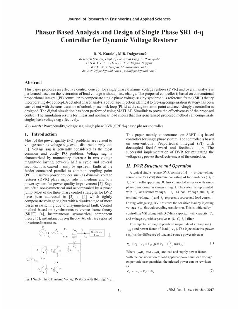
Journal of Research in Engineering and Applied Sciences JREAS, Vol. 2, Issue 01, Jan. 2017 18 Phasor Based Analysis and Design of Single Phase SRF d-q Controller for Dynamic Voltage Restorer Research Scholar, Dept. of Electrical Engg.1 Principal2 G.H.R..C.E 1 G.H.R.I.E.T. 2 Hingna, Nagpur R.T.M. N.U, Nagpur, Maharashtra, India [email protected] , [email protected]Abstract This paper proposes an effective control concept for single phase dynamic voltage restorer (DVR) and overall analysis is performed based on the restoration of load voltage without phase change. The proposed controller is based on conventional proportional integral (PI) controller to compensate single phase voltage sag by synchronous reference frame (SRF) theory incorporating d-q concept. A detailed phasor analysis of voltage injection identical to pre-sag compensation strategy has been carried out with the consideration of unlock phase lock loop (PLL) at the sag initiation point and accordingly a controller is designed. The digital simulation has been performed using MATLAB Simulink to prove the effectiveness of the proposed control. The simulation results for linear and nonlinear load shows that this generalized proposed method can compensate single phase voltage sag effectively. Key words : Power quality, voltage sag, single phase DVR, SRF d-q based phasor controller. D. N. Katole1, M.B. Daigavane2 1. Introduction Most of the power quality (PQ) problems are related to voltage such as voltage sag/swell, distorted supply etc. [1]. Voltage sag is generally considered as the most common and costly PQ problem. Voltage sag is characterized by momentary decrease in rms voltage magnitude lasting between half a cycle and several seconds. It is caused mainly by upstream faults at the feeder connected parallel to common coupling point (PCC). Custom power devices such as dynamic voltage restorer (DVR) plays major role in medium and low power system for power quality improvement [2]. Sags are often nonsymmetrical and accompanied by a phase jump. Most of the three phase control strategies for DVR have been addressed in [2] to [4] which tightly compensate voltage sag but with a disadvantage of more losses in switching due to unsymmetrical fault. Control method based on synchronous reference frame theory (SRFT) [4], instantaneous symmetrical component theory [5], instantaneous p-q theory [6], etc. are reported in various literatures. s i L i f C f L f L dc V dc C + _ s Z 1 S 2 S 3 S 4 S PCC Non-linear Load x y V s V t V L V inj Fig. 1 Single Phase Dynamic Voltage Restorer with H-Bridge VSI. This paper mainly concentrates on SRFT d-q based controller for single phase system. The controller is based on conventional Proportional integral (PI) with decoupled feed-forward and feedback loop. The successful implementation of DVR for mitigating the voltage sag proves the effectiveness of the controller. II. DVR Structure and Operation A typical single -phase DVR consist of H - bridge voltage source inverter (VSI) structure consisting of four switches ( 1 S to 4 S ) with self-supporting DC link connected in series with single phase transformer as shown in Fig. 1. The system is represented with s V as a source voltage, L V as load voltage and t V as terminal voltage, s i and L i represents source and load current. During voltage sag, DVR restores the sensitive load by injecting voltage inj V through coupling transformer. This is initiated by controlling VSI along with D C-link capacitor with capacity dc C and voltage dc V with a passive p (L f -C f -L f ) filter. This injected voltage depends on magnitude of voltage sag ( sag V ) and power factor of load ( L PF ). The injected active power ( inj P ) is the difference of load and source power given as ] cos ) ( [cos S L S L L L S L inj V V I V P P P q q- = - = (1) Where L q cos and s q cos are load and supply power factor. With the consideration of load apparent power and load voltage on per unit base quantities, the injected power can be rewritten as S S L inj V PF P q cos - = (2)
Transcript
Journal of Research in Engineering and Applied Sciences
JREAS, Vol. 2, Issue 01, Jan. 201718
Phasor Based Analysis and Design of Single Phase SRF d-q Controller for Dynamic Voltage Restorer
Research Scholar, Dept. of Electrical Engg.1 Principal2 G.H.R..C.E 1 G.H.R.I.E.T. 2 Hingna, Nagpur
This paper proposes an effective control concept for single phase dynamic voltage restorer (DVR) and overall analysis is performed based on the restoration of load voltage without phase change. The proposed controller is based on conventional proportional integral (PI) controller to compensate single phase voltage sag by synchronous reference frame (SRF) theory incorporating d-q concept. A detailed phasor analysis of voltage injection identical to pre-sag compensation strategy has been carried out with the consideration of unlock phase lock loop (PLL) at the sag initiation point and accordingly a controller is designed. The digital simulation has been performed using MATLAB Simulink to prove the effectiveness of the proposed control. The simulation results for linear and nonlinear load shows that this generalized proposed method can compensate single phase voltage sag effectively.
Key words : Power quality, voltage sag, single phase DVR, SRF d-q based phasor controller.
D. N. Katole1, M.B. Daigavane2
1. Introduction
Most of the power quality (PQ) problems are related to voltage such as voltage sag/swell, distorted supply etc. [1]. Voltage sag is generally considered as the most common and costly PQ problem. Voltage sag is characterized by momentary decrease in rms voltage magnitude lasting between half a cycle and several seconds. It is caused mainly by upstream faults at the feeder connected parallel to common coupling point (PCC). Custom power devices such as dynamic voltage restorer (DVR) plays major role in medium and low power system for power quality improvement [2]. Sags are often nonsymmetrical and accompanied by a phase jump. Most of the three phase control strategies for DVR have been addressed in [2] to [4] which tightly compensate voltage sag but with a disadvantage of more losses in switching due to unsymmetrical fault. Control method based on synchronous reference frame theory (SRFT) [4], instantaneous symmetrical component theory [5], instantaneous p-q theory [6], etc. are reported in various literatures.
si Li
fC
fL fL
dcVdcC
+
_
sZ
1S
2S
3S
4S
PCC
Non-linear Load
x
y
Vs Vt VLVinj
Fig. 1 Single Phase Dynamic Voltage Restorer with H-Bridge VSI.
This paper mainly concentrates on SRFT d-q based controller for single phase system. The controller is based on conventional Proportional integral (PI) with decoupled feed-forward and feedback loop. The successful implementation of DVR for mitigating the voltage sag proves the effectiveness of the controller.
II. DVR Structure and Operation
A typical single -phase DVR consist of H - bridge voltage
source inverter (VSI) structure consisting of four switches ( 1S to
4S ) with self-supporting DC link connected in series with single
phase transformer as shown in Fig. 1. The system is represented
with sV as a source voltage, LV
as load voltage and tV as
terminal voltage, si and Li
represents source and load current.
During voltage sag, DVR restores the sensitive load by injecting
voltage
injV
through coupling transformer. This is initiated by
controlling VSI along with D C-link capacitor with capacity dcC
and voltage dcV with a passive p
(Lf -Cf -Lf
) filter.
This injected voltage depends on magnitude of voltage sag (
sagV ) and power factor of load ( LPF ). The injected active power
( injP ) is the difference of load and source power given as
]cos)([cos S
L
SLLLSLinj
V
VIVPPP qq-=-= (1)
Where Lqcos and
sqcos are load and supply power factor.
With the consideration of load apparent power and load voltage
on per unit base
quantities, the injected power can be rewritten
as
SSLinj VPFP qcos-=
(2)
Journal of Research in Engineering and Applied Sciences
JREAS, Vol. 2, Issue 01, Jan. 201719
The injected power can be minimized by maintaining unity
power factor on supply side. 1cos =Sq (3)
The aim of DVR is to maintain load voltage magnitude to its
desired value say 1pu despite voltage sag ( sagV ) at supply end. It
gives
sagS VV -=1
(4)
Using (2), (3), and (4) the minimum injected active power can
be written as
)1(min
Lsaginj PFVP --=
(5)
From (5) it is clear that when )1( Lsag PFV -£ , load voltage
restoration is possible without active power injection.
Otherwise, it needs the support of active power to restore the load voltage. To handle power quality problems in single phase, several control strategies are available in case of shunt compensation without energy storage device like active power filter [6] but less reported in case of series compensation. The DVR effectively supply reactive power but active power is fulfilled by energy storage device [7]. In general, the active and reactive power flow are controlled by regulating the angle between injected voltage and the line current. The effective solution for maintaining exact magnitude of voltage at load without any phase change, as like a voltage before sag is pre-sag compensation method. This method leads to less distortion at the load side resulting in no transients and circulating currents. Most of the controllers earlier designed, are based on this method where locking of PLL is necessary at sag initiation point. Whereas in this paper a phasor analysis of pre-sag method has been done to obtain the magnitude and angle of injected voltage without locking the PLL. The proposed controller based on this analysis has been discussed below.
III.Proposed control system
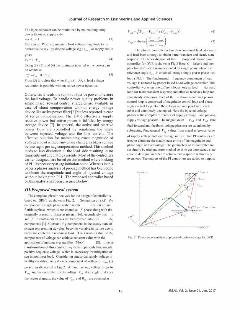
The complete phasor analysis for the design of controller is
based on SRFT
as shown in Fig. 2. Generation of SRF d-q
component in single phase system needs
creation of one
fictitious phase which is considered as â
phase along with the
originally present á
phase as given in [6]. Accordingly this á
and â
instantaneous values are transformed into SRF d-q
components [3]. Constant d-q
component in the steady state of
system representing
dc value, becomes variable in na ture due to
harmonic contents in nonlinear load.
The variable value
of d-q
components of voltage can achieve constant value with the
application of moving average filter (MAF)
[8]. Inverse
transformation of this constant d-q
value represents fundamental
positive sequence voltage
which is
necessary for mitigation of
sag in nonlinear load. Considering sinusoidal supply voltage in
healthy condition, only d -axis component of voltage ( dpreV ) is
present as illustrated in Fig. 2. At fault instant , voltage drops to
sagV and the controller injects voltage injV at an angle á. As per
the vector diagram, the value of 1injV and 1injq are obtained as
221 )()( qsagqpredsagdpreinj VVVVV -+-= (6)
÷÷
ø
ö
çç
è
æ
-
-=
dsagdpre
qsagqpre
injVV
VVArc tan1q
(7)
The phasor controller is based on combined feed -forward
and feed-back strategy to obtain better transient and steady state
response. The block diagram of the proposed phasor based
controller f or DVR is shown in Fig.3 Here, C larke’s and then
park transformation is implemented on single phase where the
reference angle preq
is obtained through single phase phase lock
loop ( PLL). The fundamental frequency component of load
voltage is restored by phasor based Load voltage controller. This
controller works on two different loops, one as feed -forward
loop for faster transient response and other as feedback loop for
zero steady state error. Each of th e above mentioned phasor
control loop is comprised of magnitude control loop and phase
angle control loop. Both these loops are independent of each
other and completely decoupled. Here the injected voltage
phasor is the complex difference of supply voltage
and pre-sag
supply voltage phasors. The magnitude of 1injV
and 2injV
(the
feed forward and feedback voltage phasors) are calculated by
subtracting fundamental dqV
values from actual reference value
of supply voltage and load voltage in SRF. Two PI controller are
used to eliminate the steady state errors of the magnitude and
phase angle of load voltage. The parameters of PI controller are
set simply by trial and error method so as to get zero steady state
error in dc signal in order to achieve fast response without any
overshoot. The outputs of the PI controllers are added to outputs
? pre? sag
?
? sag
V sag
a= ? pre+ ? inj1+ ? inj2
? pre
VLaxis
d pre( ref)
V dpre
V dsag
a (ref ) (R ea l)
q pre
ß(im aginary )
V dL Vq L
V L
Vqsa g
?in j1?
inj2
V inj
V ainj
V ßin j
Fig. 2 Phasor representation of proposed control strategy for DVR.
Journal of Research in Engineering and Applied Sciences
JREAS, Vol. 2, Issue 01, Jan. 201720
PLL
Vdqfundamental
extraction
Vdqref
Vdqref
V inj1
PI Controller Vinj2
1ph
dq
dq
1ph
Vs
VL
? PLL
? PLL
+ +
dq
1phfilter
Vdqfundamental
extraction
? inj1
? inj2PI
Controller
+ ++ +
wt
+
+_
_
sin? /cos?
VL-VsActual
Vinj(ref)
V inj
sin?
Conditional Switch
Sag Detection
PI Controller
+_
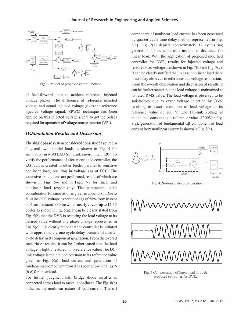
of feed-forward loop to achieve reference injected
voltage phasor. The difference of reference injected
voltage and actual injected voltage gives the reference
injected voltage signal. SPWM technique has been
applied on this injected voltage signal to get the pulses
required for operation of voltage source inverter (VSI).
Fig. 3. Model of proposed control method.
IV.Simulation Results and Discussion
The single phase system considered consists of a source, a
bus, and two parallel loads as shown in Fig. 4 for
simulation in MATLAB Simulink environment [20]. To
verify the performance of aforementioned controller, the
LG fault is created in other feeder parallel to sensitive
nonlinear load, resulting in voltage sag at PCC. The
extensive simulations are performed, results of which are
shown in Figs. 5-6 and in Figs. 7-8 for linear and
nonlinear load respectively. The parameters under
consideration for simulation is given in appendix I. Due to
fault the PCC voltage experience sag of 58% from instant
0.05sec to instant 0.30sec which nearly covers up to 12-13
cycles as shown in Fig. 5(a). It can be clearly stated from
Fig. 5(b) that the DVR is restoring the load voltage to its
desired value without any phase change represented in
Fig. 5(c). It is clearly noted that the controller is initiated
with approximately one cycle delay because of quarter
cycle delay in b component generation. From the overall
scenario of results, it can be further stated that the load
voltage is tightly restored to its reference value. The DC-
link voltage is maintained constant to its reference value
given in Fig. 6(a), load current and generation of
fundamental component from it has been shown in Figs. 6
(b-c) for linear load.
For further judgment half bridge diode rectifier is
connected across load to make it nonlinear. The Fig. 8(b)
indicates the nonlinear nature of load current. The ab
component of nonlinear load current has been generated
by quarter cycle time delay method represented in Fig.
8(c). Fig. 7(a) depicts approximately 12 cycles sag
generation for the same time instants as discussed for
linear load. With the application of proposed modified
controller for DVR, results for injected voltage and
restored load voltage are shown in Fig. 7(b) and Fig. 7(c).
It can be clearly notified that in case nonlinear load there
is no delay observed in reference load voltage restoration.
From the overall observation and discussion of results, it
can be further stated that the load voltage is maintained at
its rated RMS value. The load voltage is observed to be
satisfactory due to exact voltage injection by DVR
resulting in exact restoration of load voltage to its
reference value of 200 V. The DC-link voltage is
maintained constant to its reference value of 300V in Fig.
8(a), generation of fundamental ab component of load
current from nonlinear current is shown in Fig. 8(c).
Vinj
SensitiveLoad
VLZinj
V t
Rs Ls
PCCDVR
VS
Other Load
Fault
Fig. 4. System under consideration.
Fig. 5 Compensation of linear load through proposed controller for DVR.
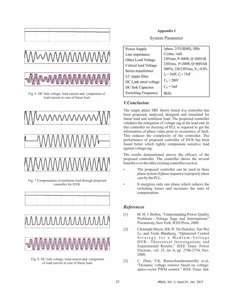
Fig. 6 DC-link voltage, load current and component of load current in case of linear load.
Fig. 7 Compensation of nonlinear load through proposed controller for DVR.
Fig. 8 DC-link voltage, load current and component of load current in case of linear load.
Appendix I
System Parameter
Power Supply
Line impedance
Other Load Voltage
Critical load Voltage
Series transformer
LC ripple filter
DC Link rated voltage
DC-link Capacitor
Switching Frequency
1phase, 215V(RMS), 50Hz
0.2ohm, 1mH
230Vrms, P=800W, Q=200VAR
230Vrms, P=200W, Q=800VAR
500VA, 230/230Vrms, X L=0.8%
Lf
= 2mH, Cf
= 15uF
Vdc
= 200V
Cdc
= 5mF
8KHz
V. Conclusion
The single phase SRF theory based d-q controller has been proposed, analyzed, designed and simulated for linear load and nonlinear load. The proposed controller validates the mitigation of voltage sag at the load end. In this controller no freezing of PLL is required to get the information of phase value prior to occurrence of fault. This reduces the complexity of the controller. The performance of proposed controller of DVR has been found better which tightly compensate sensitive load against voltage sag.
The results demonstrated proves the efficacy of the proposed controller. The controller shows the several benefits over the other existing controllers such as
• The proposed controller can be used in three phase system if phase sequence is properly taken care by the PLL.
• It energizes only one phase which reduces the switching losses and increases the time of compensation.
References
[1] M. H. J. Bollen, “Understanding Power Quality Problems—Voltage Sags and Interruptions” Piscataway, New York: IEEE Press, 2000.
[2] Christoph Meyer, Rik W. De Doncker, Yun Wei Li, and Frede Blaabjerg, “Optimized Control S t r a t e g y f o r a M e d i u m - Vo l t a g e DVR—Theoret ical Invest igat ions and Experimental Results,” IEEE Trans. Power Electron., vol. 23, no. 6, pp. 2746-2754, Nov. 2008.
[3] C. Zhan, V.K. Ramachandaramurthy et.al, “Dynamic voltage restorer based on voltage-space-vector PWM control.” IEEE Trans. Ind.
21 JREAS, Vol. 2, Issue 01, Jan. 2017
Applicat., vol. 37, no. 6, pp. 1855-1863, Nov. 2001.
[4] J. G. Nielsen, Michael Newman, Hans Nielsen, and Frede Blaabjerg,“ Control and Testing of a Dynamic Voltage Restorer (DVR) at Medium Voltage Level”, IEEE Trans. Power Electron., vol. 19, no. 3, pp. 806-813, May 2004.
[5] Mostafa I. Marei, Ehab F. El-Saadany,”A New Approach to Cont ro l DVR Based on Symmetrical components Estimation.” IEEE Trans. Power del., vol. 22, no. 4, pp. 2017-2024 Oct. 2007.
[6] V. Khadkikar, A. Chandra, B.N. Singh,” Generalised single-phase p-q theory for active power filtering: simulation and DSP-based experimental investigation” IET Power Electron., vol. 2, No. 1, pp. 67–78, 2009.
[7] Satish Samineni, B. K. Johnson “Modeling and Analysis of a Flywheel Energy Storage System for voltage Sag Correction”, IEEE Trans. Ind. Applicats., vol. 42, no. 1, pp 42-52, Jan/Feb. 2006.
[8] Sergio Augusto Oliveira da Silva, et.al., “A Compara t i ve Ana lys i s o f SRF-based Controllers Applied to Active Power Line Conditioners,” IEEE explorer, 2008.