Delft University of Technology Faculty of Electrical Engineering, Mathematics and Computer Science Master of Science Thesis Phasor Measurement Unit Testing by Nhi Nguyen Delft, The Netherlands August 2012 Copyright c 2012 by Nhi Nguyen. All rights reserved.
Prof. ir. Lou van der SluisDelft University of Technology, the Netherlands
Dr. ir. Marjan Popov (supervisor)Delft University of Technology, the Netherlands
Dr. ir. Dhiradj DjairamDelft University of Technology, the Netherlands
Dr. ir. Gert Rietveld (supervisor)VSL, the Netherlands
Preface
The thesis is the result of my 9 months working in the PMU project. Itincludes the study into PMU behavior and IEEE Synchrophasor standardsthrough simulation and measurements. Simulation is done on a softwareplatform whereas measurement is performed at a company, VSL, to test aPMU on its measurement quality.
First of all, I would like to express my special thanks to my supervisors, Dr.Marjan Popov and Dr. Gert Rietveld, for their enthusiastic guidance andvaluable suggestions and comments. I highly appreciate all their supevision,explanation, suggestions, and advice.
I also would like to thank all staff members of the EPE group for providingme with important and useful knowledge and skills throughout my two yearsof studying.
I wish to thank Alicja Lojowska, my officemate, for her kindness and hersupport during the time I have been working on my thesis. I would like tothank her for teaching me how to use Latex and for her lovely smile andsense of humor, which always makes me feel more positive.
Finally, I thank my family and friends for their understanding and support-ing during my study here.
5.9 PMU phase angle at 45Hz . . . . . . . . . . . . . . . . . . . . 625.10 PMU errors as a function of power system frequency for volt-
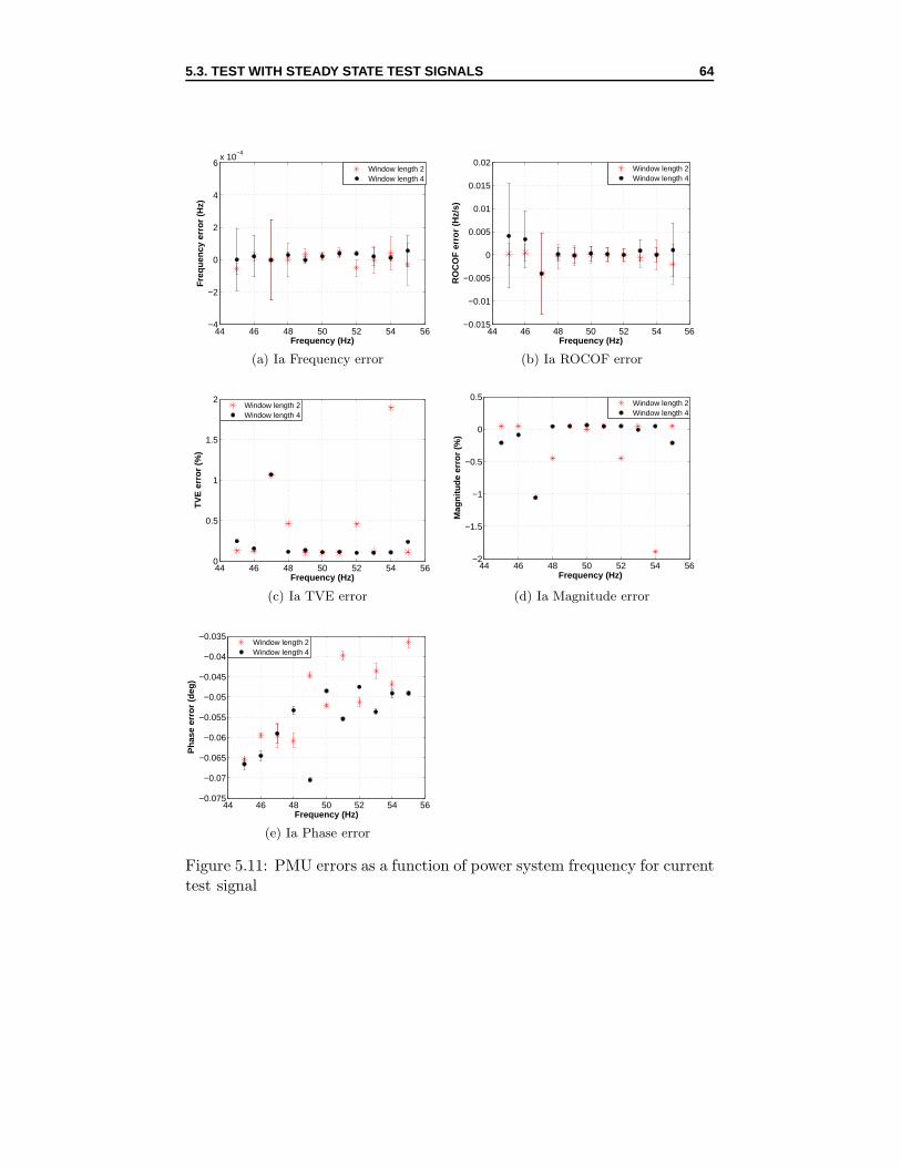
age test signal . . . . . . . . . . . . . . . . . . . . . . . . . . . 635.11 PMU errors as a function of power system frequency for cur-
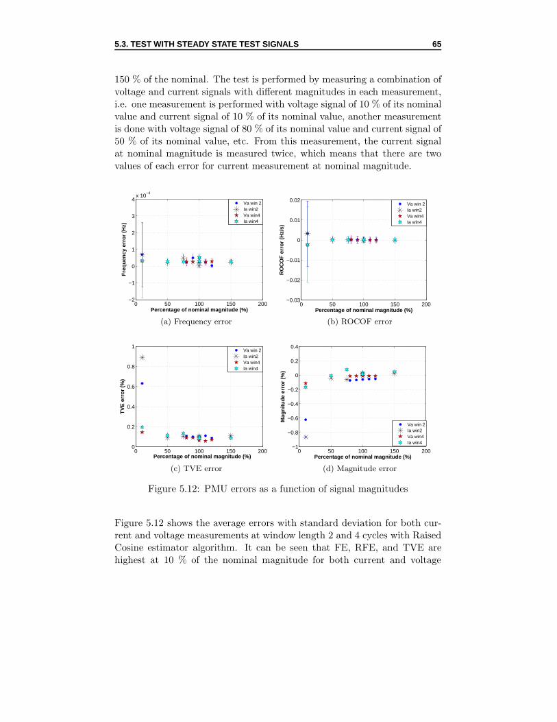
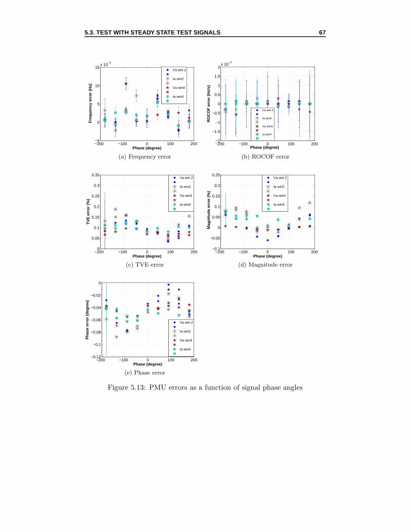
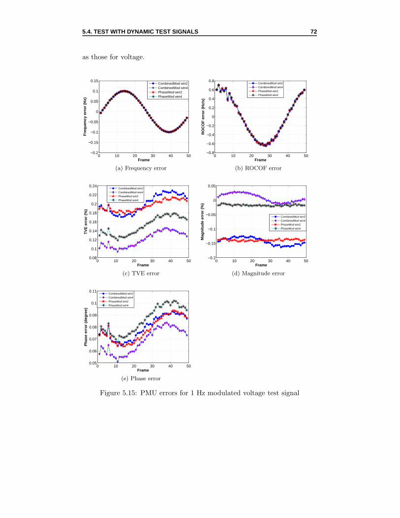
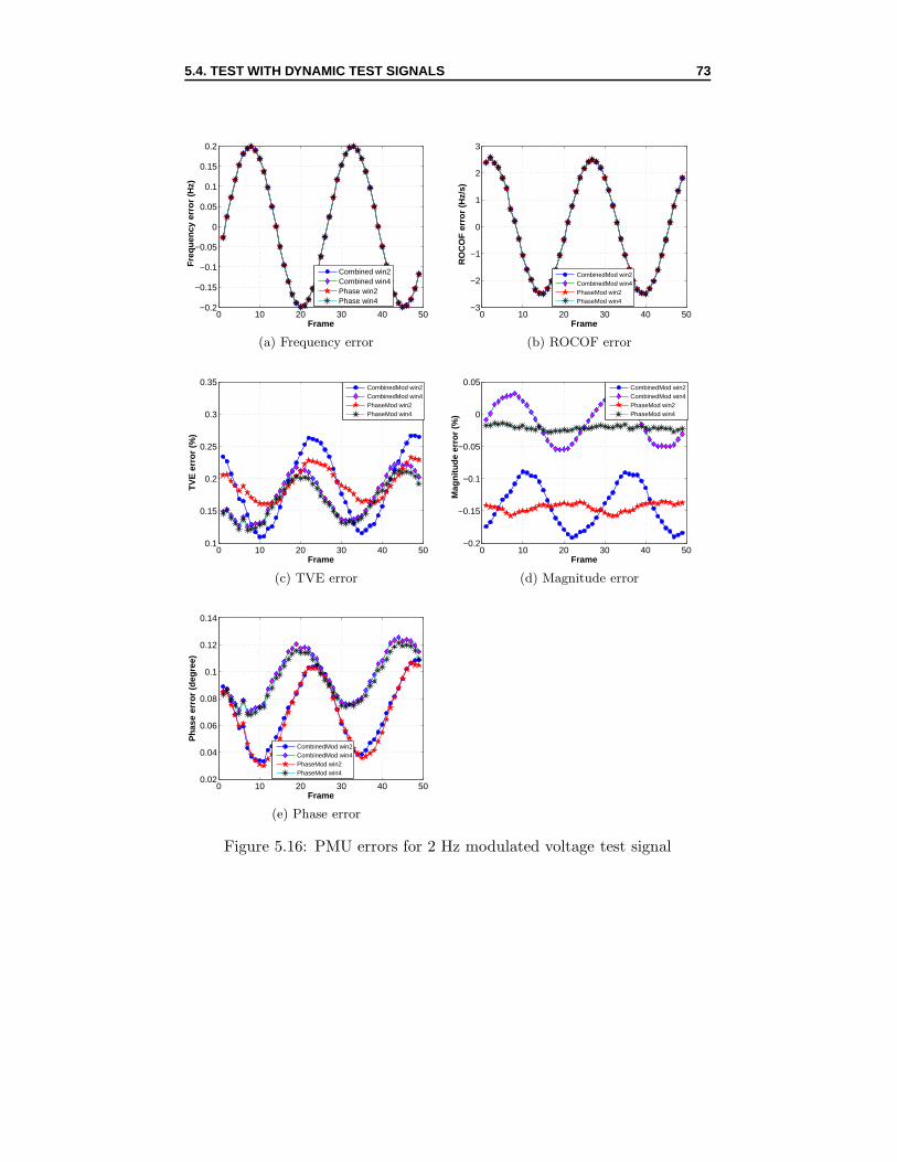
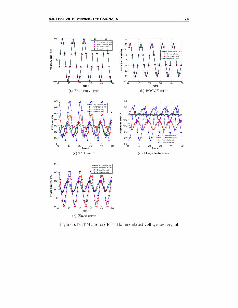
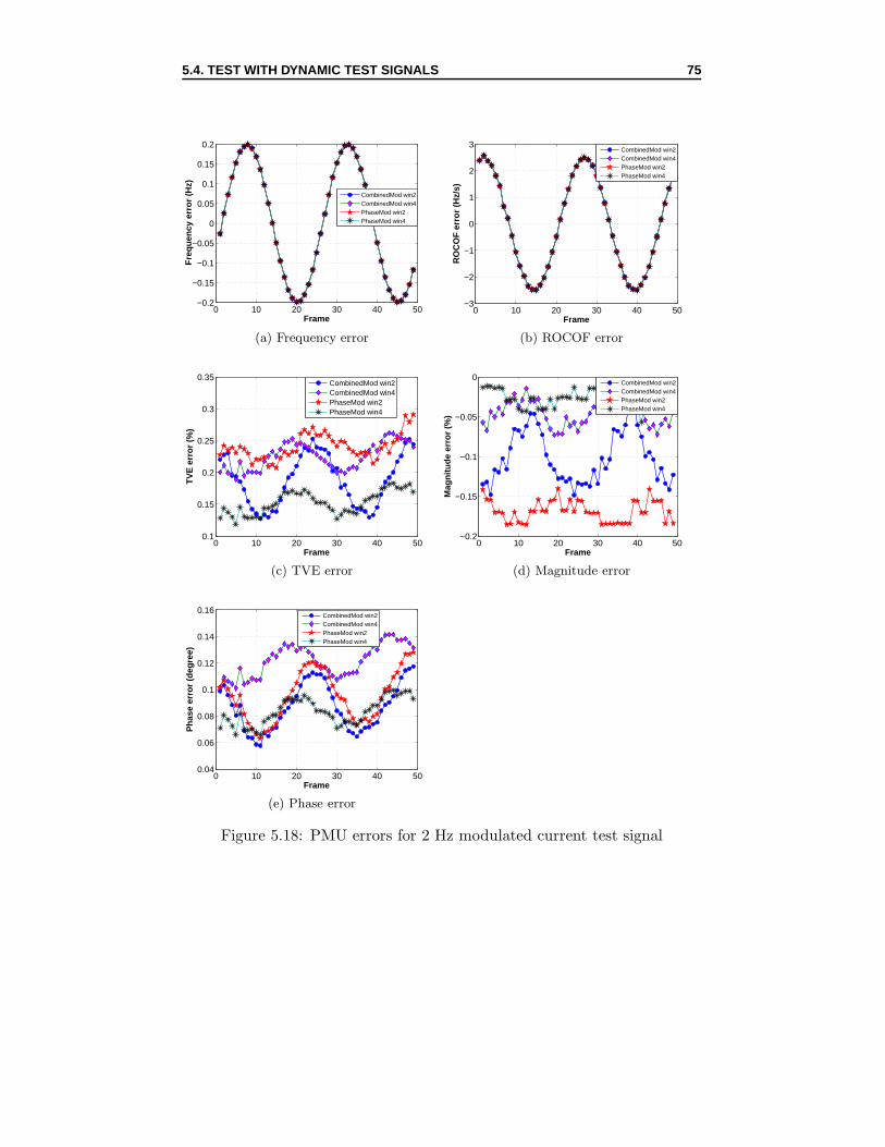
rent test signal . . . . . . . . . . . . . . . . . . . . . . . . . . 645.12 PMU errors as a function of signal magnitudes . . . . . . . . 655.13 PMU errors as a function of signal phase angles . . . . . . . . 675.14 PMU errors as a function of signal harmonic distortion . . . . 695.15 PMU errors for 1 Hz modulated voltage test signal . . . . . . 725.16 PMU errors for 2 Hz modulated voltage test signal . . . . . . 735.17 PMU errors for 5 Hz modulated voltage test signal . . . . . . 745.18 PMU errors for 2 Hz modulated current test signal . . . . . . 755.19 PMU errors for ±1 Hz frequency ramp test signal . . . . . . . 775.20 PMU response delay and overshoot for magnitude step volt-
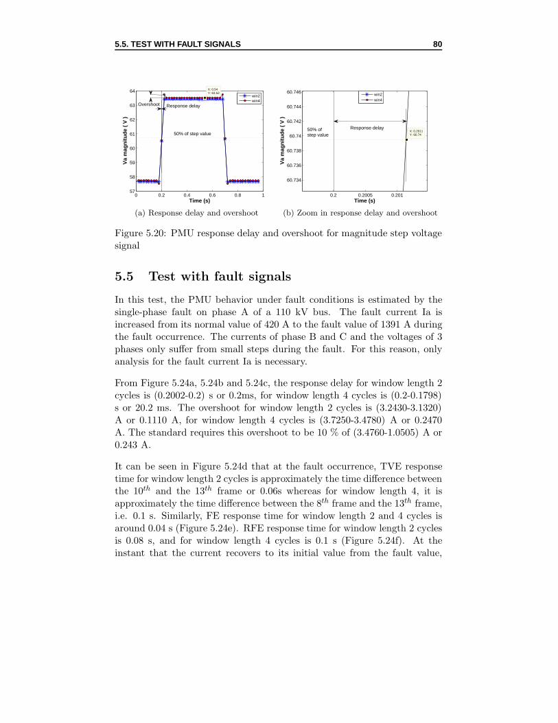
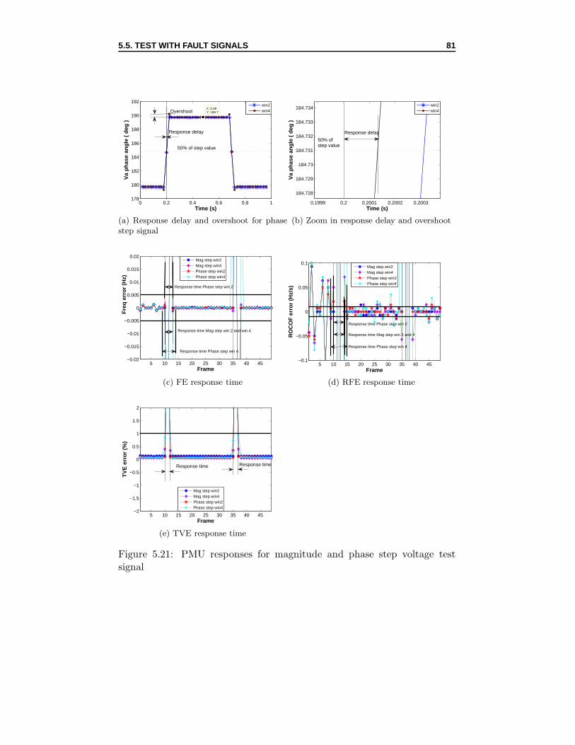
age signal . . . . . . . . . . . . . . . . . . . . . . . . . . . . . 805.21 PMU responses for magnitude and phase step voltage test
WAMPAC Wide Area Monitoring Protection And Control
WAVI Wide Area Voltage stability Index
NIST National Institute of Standard and Technology
DUT Device Under Test
CET Centre for Electric Technology
DTU Technical University of Denmark
VSL Dutch Metrology Institute
UTC Universal Time Coordinated
ROCOF Rate Of Change Of Frequency
TVE Total Vector Error
FE Frequency Error
RFE Rate of change of Frequency Error
MagE Magnitude Error
PhaE Phase Error
THD Total Harmonic Distortion
DFT Discrete Fourier Transform
DG Digitizer
I/O Input/Output
1 PPS 1 Pulse Per Second
FFT Fast Fourier Transform
Chapter 1
Introduction
Power systems often operate close to their stability limit which means thatany disturbances or faults may cause power oscillations and lead power sys-tems to a cascade outage. It is, therefore, necessary to make correct decisionson how to take actions to stabilize power systems. With the advent of clocksynchronization via Global Positioning Systems (GPSs), phasor measure-ment units (PMUs) have been introduced. PMUs are devices which producesynchronized phasor, frequency and rate of change of frequency estimatesfrom voltage and/or current and a time synchronizing signal [1]. The keydriver for PMU technology is the use of the precise time sources provided byGPS satellites to accurately measure the relative voltage and current phaseangles at buses across interconnected grids [2]. This technology is capableof directly measuring the phase angles across an interconnected power grid,which is the main advantage that PMUs have over traditional SCADAs.
PMUs are increasingly being deployed in power systems with various ap-plications such as state estimation, angle and frequency monitoring, modelderivation and validation, wide-area monitoring, protection and control, etc.Real-time data from PMUs provides significant improvements in such powersystem applications. For instance, it provides real-time monitoring and con-trol of power systems, enhancement in state estimations, real-time conges-tion management, adaptive protection, power system restoration, etc.
The requirements for PMU performance are defined in the IEEE Synchropha-sor Standard C37.118-2005 [3] and then C37.118-2011 [1]. The former stan-dard only introduces requirements for PMU steady state performance. Re-quirements for dynamic performance has been revised and incorporated intothe later standard C37.118-2011. In both standards, the measurement qual-
8
1.1. LITERATURE REVIEW 9
ity of PMUs is evaluated on the basis of the Total Vector Error (TVE)concept and benchmark tests, including the step tests on magnitude, phaseand frequency. TVE is defined as the measure of error between the theoret-ical phasor value of the signal being measured and the phasor estimate [4].The standard requires TVE to be less than 1 % under any conditions [1],[3].
1.1 Literature review
The first prototype PMU was developed in 1988 by a Virginia Tech researchteam starting from the Symmetrical Component Distance Relay algorithm.PMUs were then commercially manufactured and several innovations wereadded such as an internal GPS receiver, analog-to-digital converter data con-centrators, and modem interfaces for remote access to the PMU. After theintroduction of this new measurement device, research effort was made todevelop PMU applications in power systems. Initial PMU applications wererelated to state estimations [4]. One piece of research into state estimationsusing PMU deals with the placement of minimal sets of PMUs in order tomake the system measurement model observable and, therefore, linear. Dif-ferent algorithms have been developed to solve this problem, such as integerlinear programming, topology based or placement strategy against loss of asingle PMU, etc. Simulation results have shown that about one fourth toone third of the system buses need to be provided with PMUs for completeobservability [5].
Fault detection/location using PMU measurement has also been researched.References [6] and [7] propose an adaptive technique for fault detection/location.The papers indicate that by combining a robust fault detection/location in-dex, parameter estimation algorithm, a special filtering technique and awell-designed PMU, the proposed technique will be an adaptive, high per-formance and low-cost fault detection/location technique with an accuracyof up to 99.9 %.
Additional research has been performed about the usage of PMUs in wide-area monitoring, protection and control (WAMPAC) of power networks. In[8], an overview of PMU applications in a large-scale WAMPAC system isdescribed. The paper in question presents a typical WAMPAC architecturewith its main building blocks. It notes that the architecture depends onspecific system needs, its topology, generation profile, and the quality of thecommunication infrastructure.
1.1. LITERATURE REVIEW 10
There has also been much research into the problem of voltage stability us-ing PMUs. In [9], a Wide Area Voltage stability Index (WAVI) for dynamicsituations is proposed. In [10], an algorithm for fast detection via Theveninequivalents is described. Reference [11] deals with measuring devices. In[12], a contingency analysis and a model are proposed. Reference [13] devel-ops an index for a transmission corridor, which is based on the transmissionline capability. Reference [14] studies how PMUs can define a problem inthe network to obtain voltage regulation.
Many tests and calibrations have been performed on PMUs. Reference [15]describes the calibration system and dynamic test system for PMUs at theNational Institute of Standards and Technology (NIST). The calibration sys-tem covers all conditions that satisfy the Standard requirements accordingto several hundred individual tests. It consists of a GPS clock and a deviceunder test (DUT) connected to antennas to receive the GPS signal. Thedynamic test system has a similar basic design to the calibration system.The test signals generated have linearly varying magnitude and frequency,as well as sinusoidal and damped sinusoidal magnitude and frequency. Ref-erence [16] presents the plans and process towards the development of thedynamic PMU performance test system at NIST. An analysis model andan algorithm for taking time-synchronized signals and calculating dynamicparameters are proposed. Several test patterns for the dynamic testing ofPMUs including linearly changing magnitudes or frequencies are presented.In [17], a report on the results of PMU laboratory development and test-ing done at the Centre for Electric Technology (CET), Technical Univer-sity of Denmark (DTU) is made. According to this report, the university’sPMU named DTU-PMU is tested and compared with a commercial PMU.Three main tests, including a steady-state test, a modulation test, and a dy-namic test and harmonic rejection have been done. The dynamic tests areperformed with the amplitude scan, phase angle scan and amplitude stepsignals. The steady state tests are implemented conforming to the IEEEstandard C37.118-2005 and the test results confirm the validation of thetest setup and the performance of the DTU-PMU. Reference [18] lists initialresults using TVE to investigate PMU performance conforming to the IEEEC37.118-2005 standard. Two PMUs were tested with the signal magnitudetest, signal phase angle test, amplitude modulation test, harmonic rejectiontest and frequency ramping test. However, the TVE standard for frequencyramping test at this time (2010) is still under development (but not now in2012). It states that TVE error is mostly influenced by frequency and anglemeasurement. It also notes that a more generalized and accurate descrip-
1.2. RESEARCH OBJECTIVES 11
tion of phasor is necessary for amplitude modulation test. In [19], there is adescription of several methods for analyzing dynamic power signals sent toa PMU. These methods, Taylor Expansion and Three-Waveform method,allow these signals to be accurately characterized in terms of their ampli-tude, phase, and frequency at specific time stamps synchronized to a PMU.This, in turn, allows PMUs with a wide range of dynamic signals to beaccurately characterized. Paper [20] describes the equations for combinedphase and amplitude modulated signals as test signals. It also describesa method for analyzing such modulated signals and for providing accuratephasor estimation.
1.2 Research objectives
The research objectives of the thesis include:
• Understanding the behavior of PMUs through simulation and mea-surement; getting used to the new standard for PMU operation, i.eIEEE C37.118-2011 [1]; learning how to evaluate the measurementquality of PMUs with the requirements mentioned in the IEEE C37.118-2011 Standard; defining test signals that could be used for testingPMUs.
• Testing a PMU according to the IEEE C37.118-2011 Standard insteady state and dynamic conditions; evaluating the quality of thePMU as well as the source of errors contributing to TVE errors of thePMU with a series of test signals and different PMU setting parame-ters.
The thesis first discusses background knowledge on PMU and the field ofPMU research, then going on to present the procedures and results in testingthe Arbiter PMU. It begins with a literature review on PMU research andPMU testing and calibrating. It continues with a summary of the test signalsto be used for testing the PMU . The rest will constitute a description of allsteady state and dynamic tests together with results and conclusions.
1.3 Research methodology
The testing of the PMU is done in three steps. Firstly, the IEEE C37.118-2011 Standard has to be studied carefully to gain a general knowledge onhow to estimate the measurement quality of PMUs and define which re-quirements and which test conditions should be included in the test. Next,
1.4. ORGANIZATION OF THE THESIS 12
a series of test signals, both steady state and dynamic, are generated in com-pliance with the standard. Then, a high accuracy test setup is prepared.This test setup is responsible for the generation and measurement of con-tinuous test signals within a given test period. The generated test signalswill be supplied for the inputs of the PMU and the measured test signalswill provide the reference signals for calculating the errors of the PMU.
After all the tests have been done, the analysis will be performed by com-paring the output phasor of the PMU and the reference phasor in termsof their magnitude, phase, frequency and rate of change of frequency (RO-COF). The total vector error (TVE) is then calculated on the basis of themagnitude and phase of both phasors.
1.4 Organization of the Thesis
Chapter 1: Introduction
This chapter contains a literature review on post PMU research generallyand on PMU testing and calibrating specifically. It continues with the re-search objectives and research methodology of the thesis and ends up withoutlining the structure of the thesis.
Chapter 2: IEEE C37.118 Standards and Test signals
This chapter deals with all the test signals that will be used during the PMUtest. These signals are generated as described in the IEEE C37.118-2011Standard. This chapter also discusses the requirements on PMU operationin the IEEE C37.118-2011 Standard.
Chapter 3: PMU simulation
This chapter discusses the simulation results of the test signals with thehelp of a Software Platform provided by VSL. It provides initial insight intoPMU operation and measurement quality evaluation.
Chapter 4: PMU test setup
This chapter describes in detail the procedure of PMU testing and the mea-surement setup.
Chapter 5: PMU test results
This chapter represents the body of the work done for the thesis. It showsthe results of all measurements. It also includes discussions and evaluationson the obtained results.
1.4. ORGANIZATION OF THE THESIS 13
Chapter 6: Conclusions and Recommendations
This chapter describes the thesis conclusions and recommendations for fu-ture work.
Chapter 2
IEEE C37.118 Standards and
Test signals
2.1 IEEE C37.118 Standards
The IEEE Synchrophasor Standards C37.118-2005 [3] and C37.118-2011 [1]provide a tool for defining PMU performance requirements and standardiz-ing PMU measurement quality. The original Synchrophasor standard wasIEEE 1344-1995. This standard was then reviewed and developed into IEEEC37.118-2005 [3]. The second standard provides a measurement conventiondefinition, introduces a method of determining measurement precision, im-proves the time stamping method defined in the previous version, and pro-vides requirements for measurement under steady state conditions [21].
In compliance with the IEEE C37.118-2005, many tests on PMU perfor-mance under steady state conditions have been developed. However, theability of PMU to operate under dynamic conditions of the electric powergrid has become increasingly important. Therefore, the need for dynamicPMU testing has required additional information to be included into thecurrent standard.
The IEEE C37.118-2005 was again reviewed and replaced by the IEEEC37.118-2011 [1], which is the current standard. In this standard, addi-tional clarification for the phasor and synchronized phasor definitions hasbeen provided. The concepts of TVE and compliance tests have been re-tained and expanded. Temperature variation tests have also been added.Above all, requirements for dynamic tests have been introduced and lim-its on frequency measurement and rate of change of frequency (ROCOF)
14
2.1. IEEE C37.118 STANDARDS 15
measurement have been provided [1].
2.1.1 Synchrophasor definition
The synchrophasor or synchronized phasor measurement is the representa-tion of a sinusoidal signal with a phase angle relative to a cosine functionat the nominal system frequency synchronized to the Universal Time Co-ordinated (UTC). In other words, the UTC provides a common time basefor all PMUs. Accordingly, all PMU phase angle measurements are directlycomparable. This provides invaluable information for wide area monitoring,protection and control of the electric power networks.
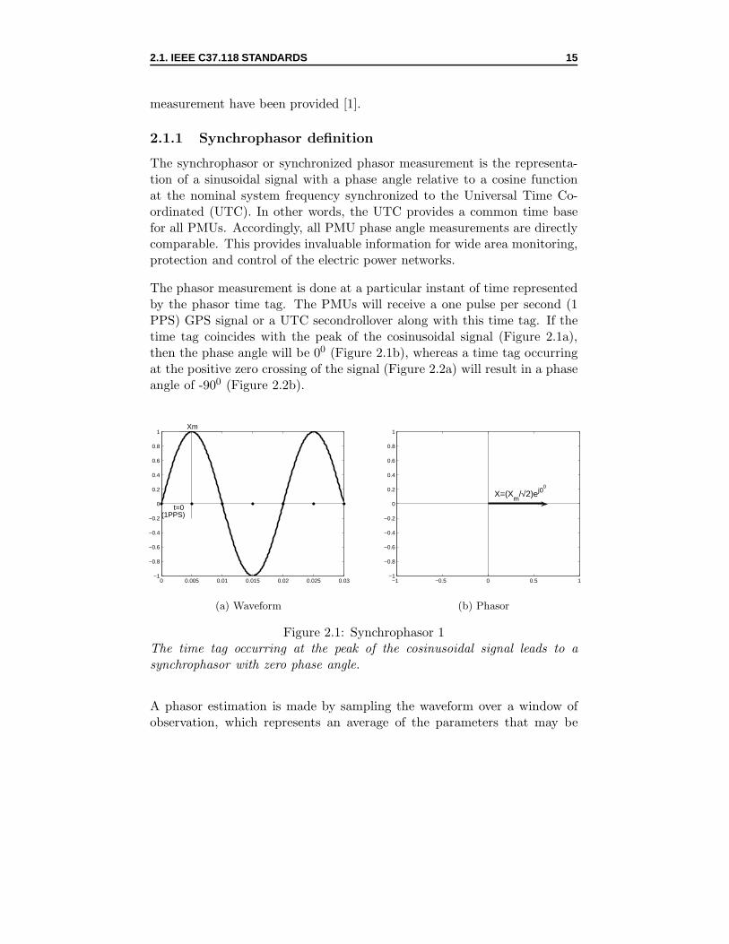
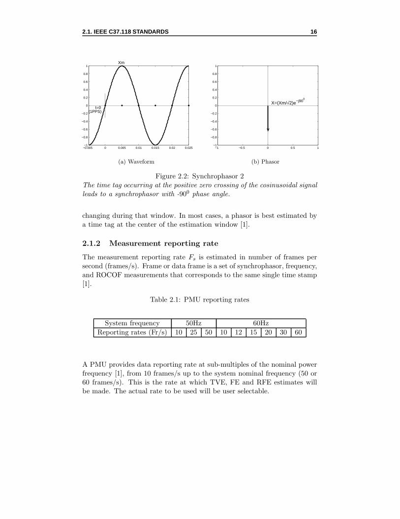
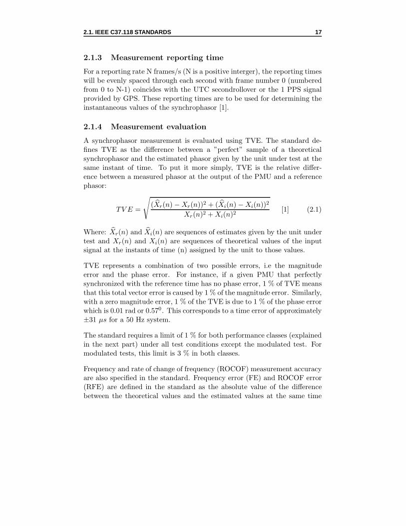
The phasor measurement is done at a particular instant of time representedby the phasor time tag. The PMUs will receive a one pulse per second (1PPS) GPS signal or a UTC secondrollover along with this time tag. If thetime tag coincides with the peak of the cosinusoidal signal (Figure 2.1a),then the phase angle will be 00 (Figure 2.1b), whereas a time tag occurringat the positive zero crossing of the signal (Figure 2.2a) will result in a phaseangle of -900 (Figure 2.2b).
0 0.005 0.01 0.015 0.02 0.025 0.03−1
−0.8
−0.6
−0.4
−0.2
0
0.2
0.4
0.6
0.8
1Xm
t=0(1PPS)
(a) Waveform
−1 −0.5 0 0.5 1−1
−0.8
−0.6
−0.4
−0.2
0
0.2
0.4
0.6
0.8
1
X=(Xm
/√2)ej00
(b) Phasor
Figure 2.1: Synchrophasor 1The time tag occurring at the peak of the cosinusoidal signal leads to asynchrophasor with zero phase angle.
A phasor estimation is made by sampling the waveform over a window ofobservation, which represents an average of the parameters that may be
2.1. IEEE C37.118 STANDARDS 16
−0.005 0 0.005 0.01 0.015 0.02 0.025−1
−0.8
−0.6
−0.4
−0.2
0
0.2
0.4
0.6
0.8
1Xm
t=0(1PPS)
(a) Waveform
−1 −0.5 0 0.5 1−1
−0.8
−0.6
−0.4
−0.2
0
0.2
0.4
0.6
0.8
1
X=(Xm/√2)e−j900
(b) Phasor
Figure 2.2: Synchrophasor 2The time tag occurring at the positive zero crossing of the cosinusoidal signalleads to a synchrophasor with -900 phase angle.
changing during that window. In most cases, a phasor is best estimated bya time tag at the center of the estimation window [1].
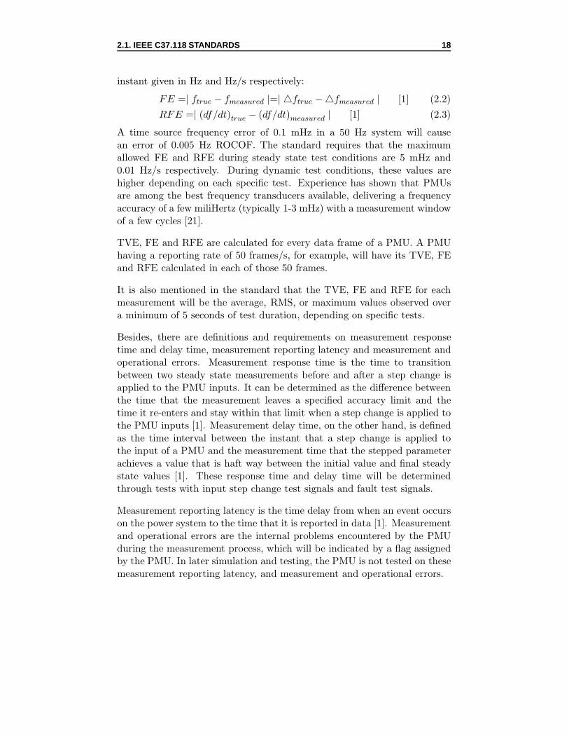
2.1.2 Measurement reporting rate
The measurement reporting rate Fs is estimated in number of frames persecond (frames/s). Frame or data frame is a set of synchrophasor, frequency,and ROCOF measurements that corresponds to the same single time stamp[1].
Table 2.1: PMU reporting rates
System frequency 50Hz 60Hz
Reporting rates (Fr/s) 10 25 50 10 12 15 20 30 60
A PMU provides data reporting rate at sub-multiples of the nominal powerfrequency [1], from 10 frames/s up to the system nominal frequency (50 or60 frames/s). This is the rate at which TVE, FE and RFE estimates willbe made. The actual rate to be used will be user selectable.
2.1. IEEE C37.118 STANDARDS 17
2.1.3 Measurement reporting time
For a reporting rate N frames/s (N is a positive interger), the reporting timeswill be evenly spaced through each second with frame number 0 (numberedfrom 0 to N-1) coincides with the UTC secondrollover or the 1 PPS signalprovided by GPS. These reporting times are to be used for determining theinstantaneous values of the synchrophasor [1].
2.1.4 Measurement evaluation
A synchrophasor measurement is evaluated using TVE. The standard de-fines TVE as the difference between a ”perfect” sample of a theoreticalsynchrophasor and the estimated phasor given by the unit under test at thesame instant of time. To put it more simply, TVE is the relative differ-ence between a measured phasor at the output of the PMU and a referencephasor:
TV E =
√(X̂r(n)−Xr(n))2 + (X̂i(n)−Xi(n))2
Xr(n)2 +Xi(n)2[1] (2.1)
Where: X̂r(n) and X̂i(n) are sequences of estimates given by the unit undertest and Xr(n) and Xi(n) are sequences of theoretical values of the inputsignal at the instants of time (n) assigned by the unit to those values.
TVE represents a combination of two possible errors, i.e the magnitudeerror and the phase error. For instance, if a given PMU that perfectlysynchronized with the reference time has no phase error, 1 % of TVE meansthat this total vector error is caused by 1 % of the magnitude error. Similarly,with a zero magnitude error, 1 % of the TVE is due to 1 % of the phase errorwhich is 0.01 rad or 0.570. This corresponds to a time error of approximately±31 µs for a 50 Hz system.
The standard requires a limit of 1 % for both performance classes (explainedin the next part) under all test conditions except the modulated test. Formodulated tests, this limit is 3 % in both classes.
Frequency and rate of change of frequency (ROCOF) measurement accuracyare also specified in the standard. Frequency error (FE) and ROCOF error(RFE) are defined in the standard as the absolute value of the differencebetween the theoretical values and the estimated values at the same time
A time source frequency error of 0.1 mHz in a 50 Hz system will causean error of 0.005 Hz ROCOF. The standard requires that the maximumallowed FE and RFE during steady state test conditions are 5 mHz and0.01 Hz/s respectively. During dynamic test conditions, these values arehigher depending on each specific test. Experience has shown that PMUsare among the best frequency transducers available, delivering a frequencyaccuracy of a few miliHertz (typically 1-3 mHz) with a measurement windowof a few cycles [21].
TVE, FE and RFE are calculated for every data frame of a PMU. A PMUhaving a reporting rate of 50 frames/s, for example, will have its TVE, FEand RFE calculated in each of those 50 frames.
It is also mentioned in the standard that the TVE, FE and RFE for eachmeasurement will be the average, RMS, or maximum values observed overa minimum of 5 seconds of test duration, depending on specific tests.
Besides, there are definitions and requirements on measurement responsetime and delay time, measurement reporting latency and measurement andoperational errors. Measurement response time is the time to transitionbetween two steady state measurements before and after a step change isapplied to the PMU inputs. It can be determined as the difference betweenthe time that the measurement leaves a specified accuracy limit and thetime it re-enters and stay within that limit when a step change is applied tothe PMU inputs [1]. Measurement delay time, on the other hand, is definedas the time interval between the instant that a step change is applied tothe input of a PMU and the measurement time that the stepped parameterachieves a value that is haft way between the initial value and final steadystate values [1]. These response time and delay time will be determinedthrough tests with input step change test signals and fault test signals.
Measurement reporting latency is the time delay from when an event occurson the power system to the time that it is reported in data [1]. Measurementand operational errors are the internal problems encountered by the PMUduring the measurement process, which will be indicated by a flag assignedby the PMU. In later simulation and testing, the PMU is not tested on thesemeasurement reporting latency, and measurement and operational errors.
2.2. TEST SIGNALS 19
2.1.5 Measurement compliance
The standard requires all compliance measurements to be evaluated by aclass of performance. There are two classes of PMU performance definedin the standard: the P class and the M class. The P class refers to Pro-tection application, which requires fast response while the M class standsfor Measurement application which requires greater precision and does notrequire the quickest reporting rate. This class of performance is providedby the vendor or it can be user selectable if the vendor provides both P andM classes.
All compliance tests are to be performed with all the parameters set to stan-dard reference conditions, except those being varied during each specific test[1]. Such reference conditions for all tests are nominal voltage; nominal cur-rent; nominal frequency; constant voltage, current, phase and frequency;signal THD of less than 0.2 % of the fundamental.
2.2 Test signals
To prepare for PMU simulation and measurement, a series of test signalsincluding steady state and dynamic signals have been generated in compli-ance with the IEEE C37.118-2011 standard. These test signals are used fortesting the accuracy and response of PMUs under steady state and dynamicconditions. The steady state test signals consist of frequency, magnitude,phase and harmonic distortion test signals. The dynamic test signals includemodulation, frequency ramp and step test signals. A short circuit currenthas also been generated to test the ability of the PMU during fault condi-tions. This fault current test signal is not required by [1]. Since the PMUused in later simulation and testing is single phase, all test signals will begenerated for 1 phase, i.e phase A.
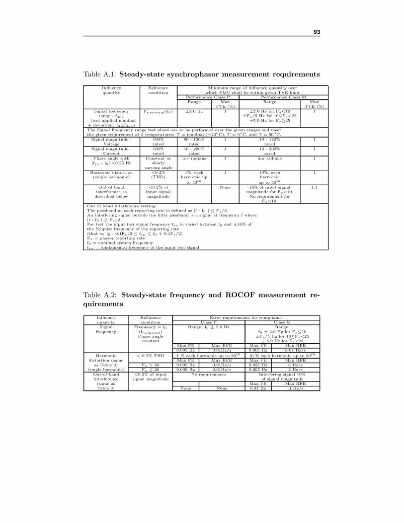
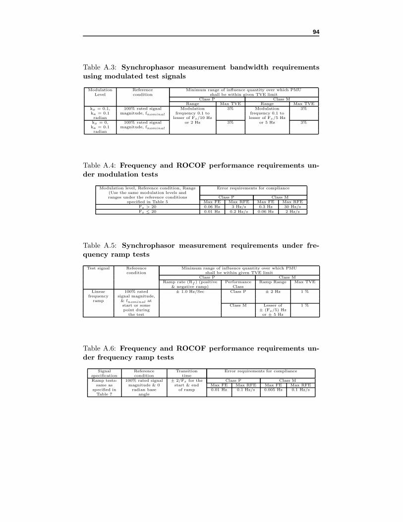
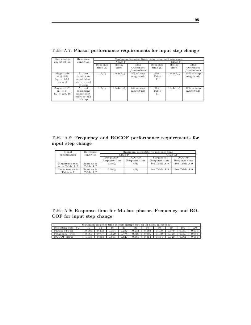
Specific requirements, reference condition as well as range of influence quan-tity over which the PMU will be within its limits for each steady state anddynamic test signals provided in the standard are presented in Appendix A.
The PMU used in the later simulation and testing will be of performanceclass M and reporting rate 50 frames/s. Each test signal is, therefore, pro-duced in conformity with the reference condition and the range defined forclass M and reporting rate 50 frames/s in the standard. Additionally, mostparameters of the steady state and dynamic test signals will be varied fol-lowing the testing guide for steady state and dynamic performance tests
2.2. TEST SIGNALS 20
described in [22].
2.2.1 Steady state test signals
Basically, a single-phase steady state test signal are generated with a cosi-nusoidal form, nominal magnitude, nominal frequency and constant phaseangle:
X = Xm cos(ω0t+ ϕ) (2.4)
Where: Xm: nominal magnitudeω0=2πf0: nominal frequency in rad/sϕ: phase angle
The generated test signals have the nominal rms voltage and nominal rmscurrent of the Dutch power grid, i.e 100/
√(3) Vrms and 1 Arms, nominal
frequency of 50 Hz, and nominal phase angle of 00. Each test signal is gen-erated using Matlab for a duration of 1 second and a sampling frequency of200 kHz (time step of 5 ∗ 10−6 sec or 5 µs).
The idea of the steady state test is to change one fundamental parameteraround its nominal value while keeping others constant. The fundamentalparameters of a sinusoidal waveform are magnitude, phase angle, and fre-quency. Therefore, each steady state test signal corresponds to the variationof each of these parameters. In addition, according to the standard, anothersteady state test signal which includes 10 % each harmonic is used for test-ing the harmonic rejection capability of the PMU.
In Table A.1 and A.2 of Appendix A, measurement requirements by thestandard for steady state conditions are described. It can be seen in thesetables that there are requirements for signal frequency test, signal magni-tude test, signal phase angle test, harmonic distortion test, and out of bandinterference test, which means 5 steady state tests should be done with thePMU. However, due to time limit, only the first 4 tests will be performedand thus the corresponding first 4 test signals will be generated.
For signal frequency testing:
According to the standard, for class M at reporting rate Fs ≥ 25 frames/s,frequencies of the test signals have to be varied around the nominal fre-quency by ±5 Hz. All other parameters of the signal are kept at nominalconditions. In [22], the frequency in a signal frequency test of a 50 Hz sys-tem is suggested to be varied as follows:
2.2. TEST SIGNALS 21
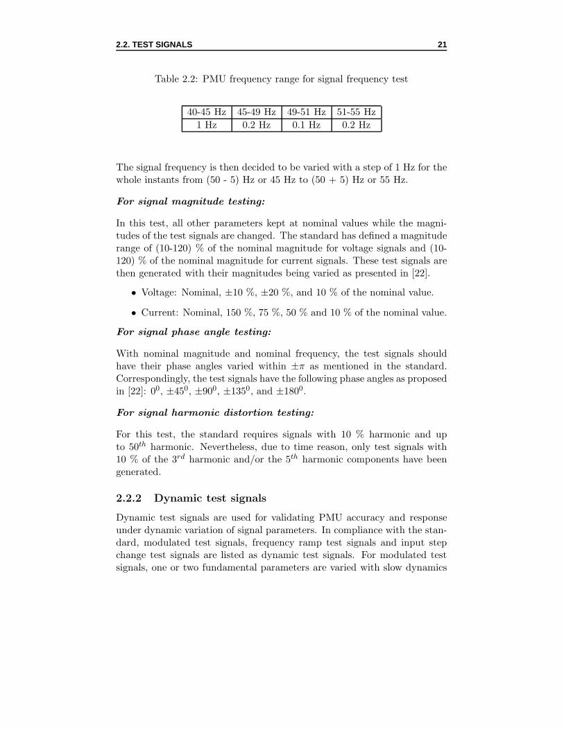
Table 2.2: PMU frequency range for signal frequency test
40-45 Hz 45-49 Hz 49-51 Hz 51-55 Hz
1 Hz 0.2 Hz 0.1 Hz 0.2 Hz
The signal frequency is then decided to be varied with a step of 1 Hz for thewhole instants from (50 - 5) Hz or 45 Hz to (50 + 5) Hz or 55 Hz.
For signal magnitude testing:
In this test, all other parameters kept at nominal values while the magni-tudes of the test signals are changed. The standard has defined a magnituderange of (10-120) % of the nominal magnitude for voltage signals and (10-120) % of the nominal magnitude for current signals. These test signals arethen generated with their magnitudes being varied as presented in [22].
• Voltage: Nominal, ±10 %, ±20 %, and 10 % of the nominal value.
• Current: Nominal, 150 %, 75 %, 50 % and 10 % of the nominal value.
For signal phase angle testing:
With nominal magnitude and nominal frequency, the test signals shouldhave their phase angles varied within ±π as mentioned in the standard.Correspondingly, the test signals have the following phase angles as proposedin [22]: 00, ±450, ±900, ±1350, and ±1800.
For signal harmonic distortion testing:
For this test, the standard requires signals with 10 % harmonic and upto 50th harmonic. Nevertheless, due to time reason, only test signals with10 % of the 3rd harmonic and/or the 5th harmonic components have beengenerated.
2.2.2 Dynamic test signals
Dynamic test signals are used for validating PMU accuracy and responseunder dynamic variation of signal parameters. In compliance with the stan-dard, modulated test signals, frequency ramp test signals and input stepchange test signals are listed as dynamic test signals. For modulated testsignals, one or two fundamental parameters are varied with slow dynamics
2.2. TEST SIGNALS 22
while others are kept constant. For frequency ramp test signals, a linearramp is applied to the frequency while the other two parameters are con-stant at nominal values. For input step change test signals, a sudden changein magnitude or phase angle occurs at a certain time while other fundamen-tal parameters remain constant. In the standard, these dynamic test signalsare formulated for three phases. For the purpose of simulating and testing,however, only single-phase test signal is needed and hence only single-phasedynamic test signals, i.e. test signals phase A, are generated.
Table A.3 to A.7 of Appendix A represent the requirements for PMU dy-namic tests, including modulated test, frequency ramp test and step changetest.
Modulated test signals:
These test signals are used for evaluating PMU responses to different typesof power signal modulation. It includes combined magnitude and phasemodulated signals and phase modulated signals with different modulationfrequencies. The standard requires TVE, FE and RFE to be measured overat least two full cycles of modulation. A three-phase modulated test signalcan be mathematically expressed as [1]:
Xa = Xm[1 + kx cos(ωt)] ∗ cos[ω0t+ ka cos(ωt− π)] (2.5)
Where: Xa, Xb, Xc: modulated signals of phase A, phase B, phase CXm: nominal magnitude of the test signalω0 = 2πf0: nominal power system frequency (rad/s)ω = 2πf : modulation frequency (rad/s)kx: amplitude modulation factorka: phase angle modulation factor.
• For combined modulated signal: kx=0.1; ka=0.1 (rad)
• For phase modulated signal: kx=0; ka=0.1 (rad)
According to the standard, for performance class M, the modulation fre-quency should be varied from 0.1 Hz to less than Fs/5 Hz (10 Hz) or 5 Hz.The test signal is then generated with modulation frequency varied between0.1 Hz and 10 Hz as depicted in [22] as follows:
2.2. TEST SIGNALS 23
Table 2.3: PMU modulation frequency range
0.2 Hz to 2 Hz 2 Hz to 10 Hz
Every 0.2 Hz Every 0.5 Hz
0 0.1 0.2 0.3 0.4 0.5−2
−1.5
−1
−0.5
0
0.5
1
1.5
2
Time(s)
X
(a) 5 Hz combined modulated signal
0 0.05 0.1 0.15 0.2−1.5
−1
−0.5
0
0.5
1
1.5
Time(s)
X
Modulated signalSinusoidal signal
(b) 10 Hz phase modulated signal
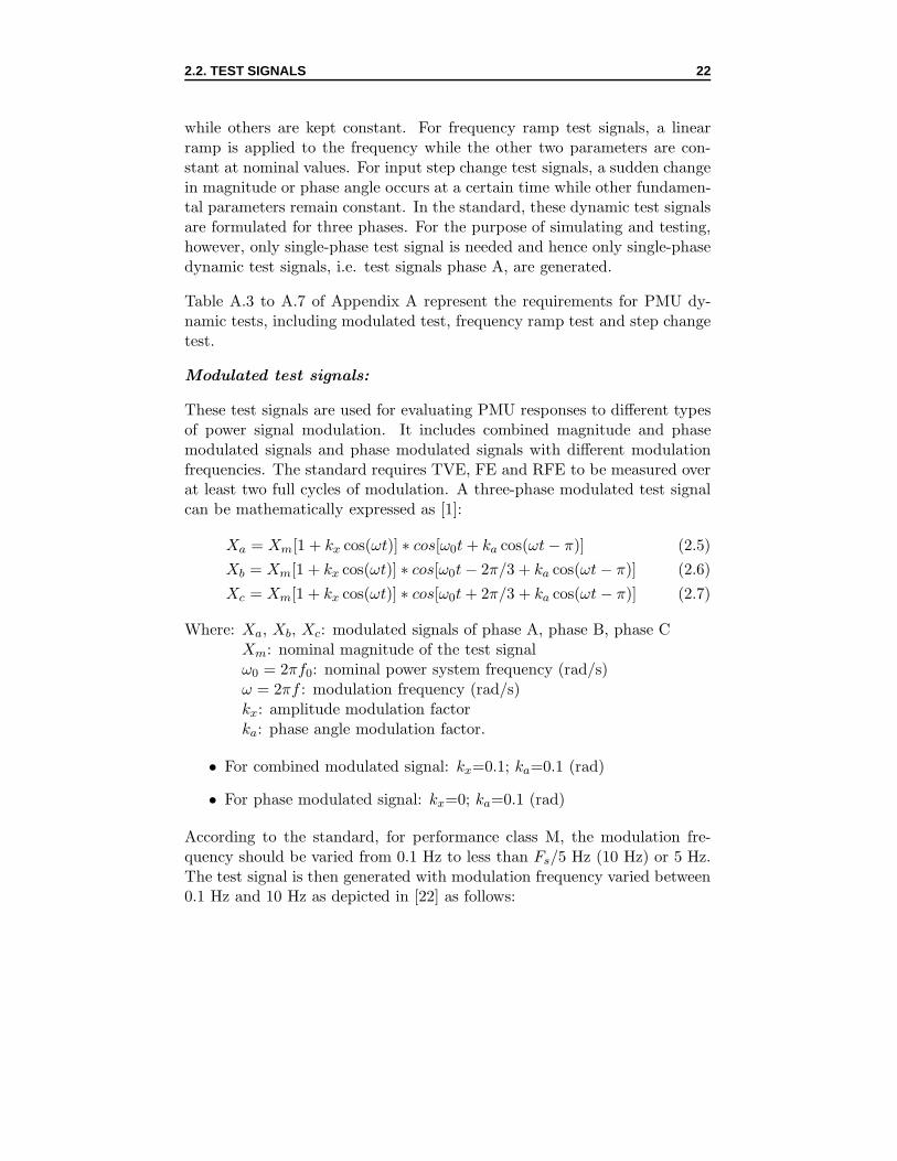
Figure 2.3: Combined modulated test signal at 5 Hz modulation frequency(kx = 0.1; ka = 0.1; f=5Hz) and phase modulated test signal at 10 Hzmodulation frequency (kx = 0; ka = 0.1; f=10Hz)
Examples of modulated test signals can be seen on Figure 2.3a and 2.3b.
Frequency ramp test signals:
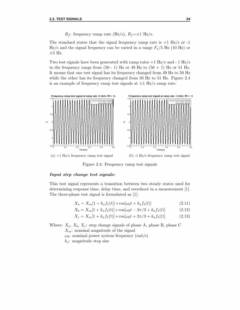
These test signals have a linear ramp frequency with a ramp rate ofRf=df/dt.Other fundamental parameters are kept constant. The standard states thatfor a frequency ramp test, the allowed TVE, FE and RFE may be exceededduring a transition period before and after a sudden change in ROCOF.Mathematically, the three-phase test signal is represented by [1]:
Xa = Xm cos(ω0t+ πRf t2) (2.8)
Xb = Xm cos(ω0t− 2π/3 + πRf t2) (2.9)
Xc = Xm cos(ω0t+ 2π/3 + πRf t2) (2.10)
Where: Xa, Xb, Xc: frequency ramp signals of phase A, phase B, phase CXm: nominal magnitude of the signalω0: nominal power system frequency (rad/s)
2.2. TEST SIGNALS 24
Rf : frequency ramp rate (Hz/s), Rf=±1 Hz/s.
The standard states that the signal frequency ramp rate is +1 Hz/s or -1Hz/s and the signal frequency can be varied in a range Fs/5 Hz (10 Hz) or±5 Hz.
Two test signals have been generated with ramp rates +1 Hz/s and - 1 Hz/sin the frequency range from (50 - 1) Hz or 49 Hz to (50 + 1) Hz or 51 Hz.It means that one test signal has its frequency changed from 49 Hz to 50 Hzwhile the other has its frequency changed from 50 Hz to 51 Hz. Figure 2.4is an example of frequency ramp test signals at ±1 Hz/s ramp rate.
0 0.1 0.2 0.3 0.4 0.5−1.5
−1
−0.5
0
0.5
1
1.5Frequency ramp test signal at ramp rate +1 Hz/s: Rf = +1
Time(s)
X
Freq ramp signalSinusoidal signal
(a) +1 Hz/s frequency ramp test signal
0 0.1 0.2 0.3 0.4 0.5−1.5
−1
−0.5
0
0.5
1
1.5Frequency ramp test signal at ramp rate −1 Hz/s: Rf = −1
Time(s)
X
Freq ramp signalSinusoidal signal
(b) -1 Hz/s frequency ramp test signal
Figure 2.4: Frequency ramp test signals
Input step change test signals:
This test signal represents a transition between two steady states used fordetermining response time, delay time, and overshoot in a measurement [1].The three-phase test signal is formulated as [1]:
Where: Xa, Xb, Xc: step change signals of phase A, phase B, phase CXm: nominal magnitude of the signalω0: nominal power system frequency (rad/s)kx: magnitude step size
2.2. TEST SIGNALS 25
ka: phase step sizef1(t): unit step function and
f1(t− t1) =
{0 if t < t1
1 if t > t1(2.14)
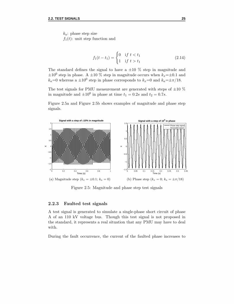
The standard defines the signal to have a ±10 % step in magnitude and±100 step in phase. A ±10 % step in magnitude occurs when kx=±0.1 andka=0 whereas a ±100 step in phase corresponds to kx=0 and ka=±π/18.
The test signals for PMU measurement are generated with steps of ±10 %in magnitude and ±100 in phase at time t1 = 0.2s and t2 = 0.7s.
Figure 2.5a and Figure 2.5b shows examples of magnitude and phase stepsignals.
0 0.2 0.4 0.6 0.8 1−2
−1.5
−1
−0.5
0
0.5
1
1.5
2
Time (s)
X
Signal with a step of ±10% in magnitude
(a) Magnitude step (kx = ±0.1; ka = 0)
0 0.05 0.1 0.15 0.2 0.25 0.3 0.35−1.5
−1
−0.5
0
0.5
1
1.5
Time (s)
XSignal with a step of 10 0 in phase
Phase step signalSinusoidal signal
(b) Phase step (kx = 0; ka = ±π/18)
Figure 2.5: Magnitude and phase step test signals
2.2.3 Faulted test signals
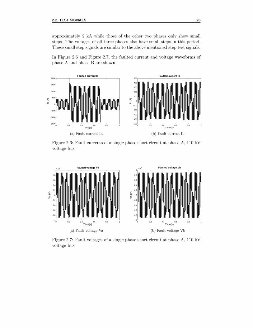
A test signal is generated to simulate a single-phase short circuit of phaseA of an 110 kV voltage bus. Though this test signal is not proposed inthe standard, it represents a real situation that any PMU may have to dealwith.
During the fault occurrence, the current of the faulted phase increases to
2.2. TEST SIGNALS 26
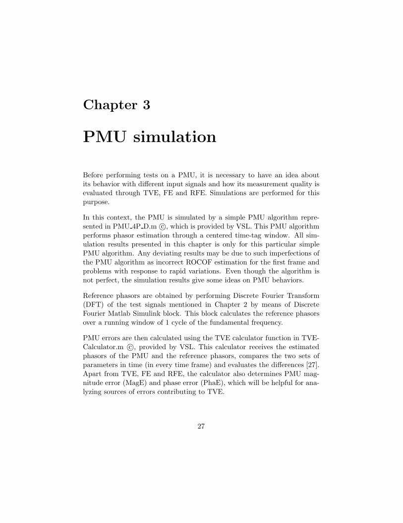
approximately 2 kA while those of the other two phases only show smallsteps. The voltages of all three phases also have small steps in this period.These small step signals are similar to the above mentioned step test signals.
In Figure 2.6 and Figure 2.7, the faulted current and voltage waveforms ofphase A and phase B are shown.
0 0.2 0.4 0.6 0.8 1−1500
−1000
−500
0
500
1000
1500
2000Faulted current Ia
Time(s)
Ia (A
)
(a) Fault current Ia
0 0.2 0.4 0.6 0.8 1−500
−400
−300
−200
−100
0
100
200
300
400
500Faulted current Ib
Time(s)Ib
(A)
(b) Fault current Ib
Figure 2.6: Fault currents of a single phase short circuit at phase A, 110 kVvoltage bus
0 0.2 0.4 0.6 0.8 1−1
−0.8
−0.6
−0.4
−0.2
0
0.2
0.4
0.6
0.8
1x 10
5 Faulted voltage Va
Time(s)
Va
(V)
(a) Fault voltage Va
0 0.2 0.4 0.6 0.8 1−1
−0.8
−0.6
−0.4
−0.2
0
0.2
0.4
0.6
0.8
1x 10
5 Faulted voltage Vb
Time(s)
Vb
(V)
(b) Fault voltage Vb
Figure 2.7: Fault voltages of a single phase short circuit at phase A, 110 kVvoltage bus
Chapter 3
PMU simulation
Before performing tests on a PMU, it is necessary to have an idea aboutits behavior with different input signals and how its measurement quality isevaluated through TVE, FE and RFE. Simulations are performed for thispurpose.
Reference phasors are obtained by performing Discrete Fourier Transform(DFT) of the test signals mentioned in Chapter 2 by means of DiscreteFourier Matlab Simulink block. This block calculates the reference phasorsover a running window of 1 cycle of the fundamental frequency.
In all simulations, the PMU algorithm performs phasor estimation with win-dow length 1 cycle, PMU reporting rate 50 frames/s, and PMU class M. Itmeans only standards for this specific reporting rate and PMU type are in-cluded.
The simulation is done for steady state, dynamic, and fault signals.
3.1 Simulation with steady state test signals
The measurement quality of the PMU algorithm at steady state conditionsis evaluated through all steady state test signals described in part 2.2.1.
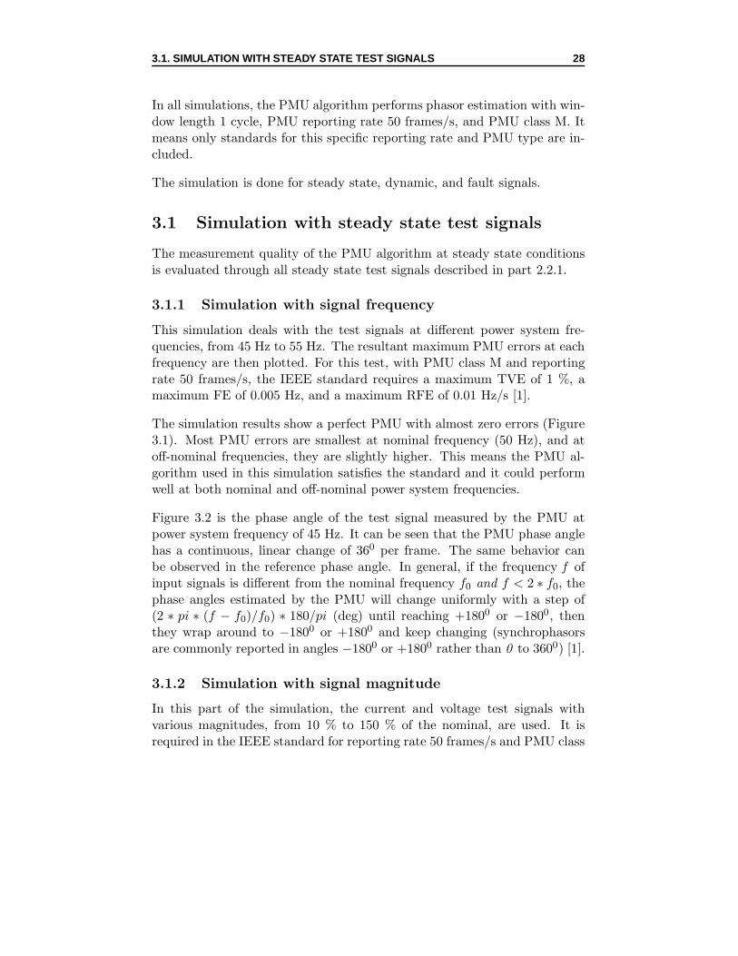
3.1.1 Simulation with signal frequency
This simulation deals with the test signals at different power system fre-quencies, from 45 Hz to 55 Hz. The resultant maximum PMU errors at eachfrequency are then plotted. For this test, with PMU class M and reportingrate 50 frames/s, the IEEE standard requires a maximum TVE of 1 %, amaximum FE of 0.005 Hz, and a maximum RFE of 0.01 Hz/s [1].
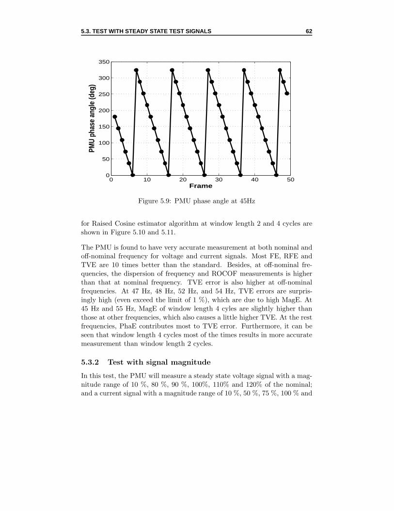
The simulation results show a perfect PMU with almost zero errors (Figure3.1). Most PMU errors are smallest at nominal frequency (50 Hz), and atoff-nominal frequencies, they are slightly higher. This means the PMU al-gorithm used in this simulation satisfies the standard and it could performwell at both nominal and off-nominal power system frequencies.
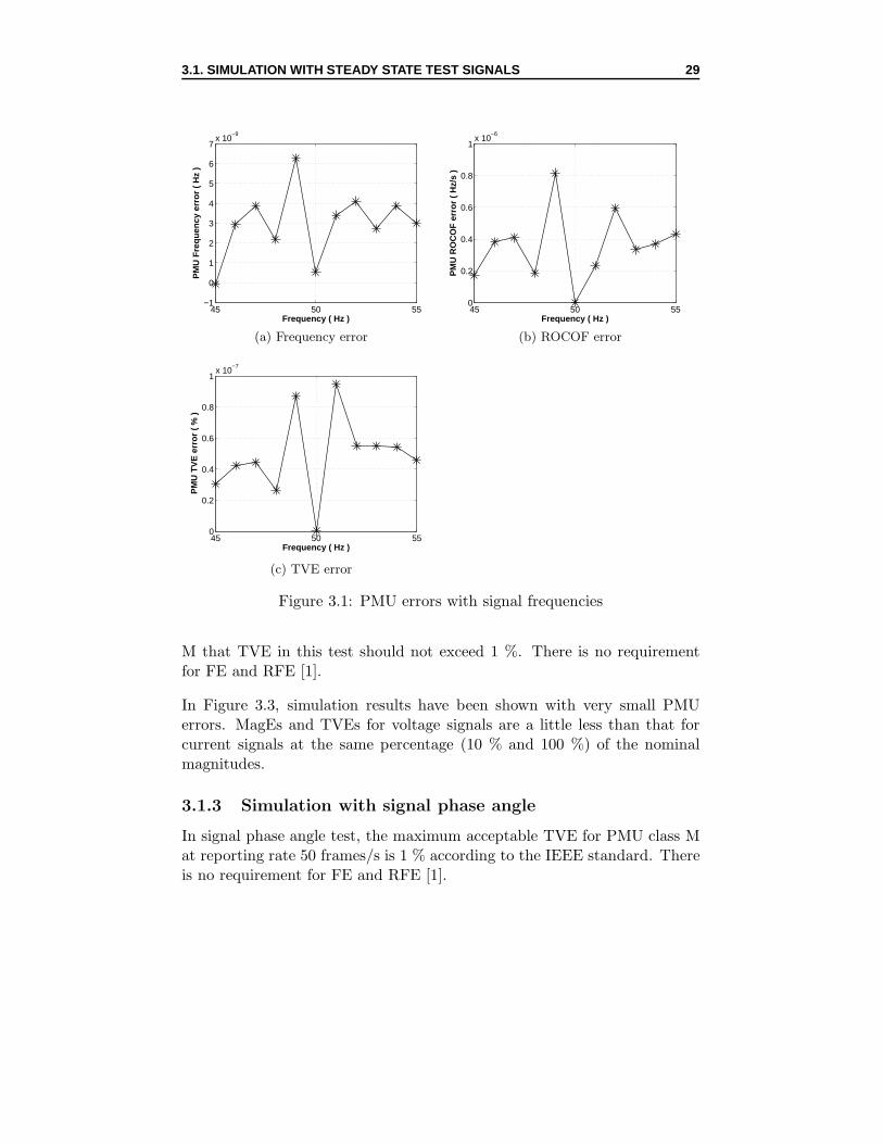
Figure 3.2 is the phase angle of the test signal measured by the PMU atpower system frequency of 45 Hz. It can be seen that the PMU phase anglehas a continuous, linear change of 360 per frame. The same behavior canbe observed in the reference phase angle. In general, if the frequency f ofinput signals is different from the nominal frequency f0 and f < 2 ∗ f0, thephase angles estimated by the PMU will change uniformly with a step of(2 ∗ pi ∗ (f − f0)/f0) ∗ 180/pi (deg) until reaching +1800 or −1800, thenthey wrap around to −1800 or +1800 and keep changing (synchrophasorsare commonly reported in angles −1800 or +1800 rather than 0 to 3600) [1].
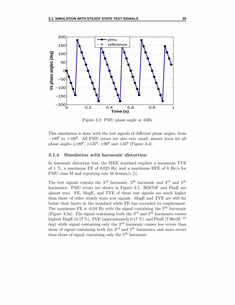
3.1.2 Simulation with signal magnitude
In this part of the simulation, the current and voltage test signals withvarious magnitudes, from 10 % to 150 % of the nominal, are used. It isrequired in the IEEE standard for reporting rate 50 frames/s and PMU class
3.1. SIMULATION WITH STEADY STATE TEST SIGNALS 29
45 50 55−1
0
1
2
3
4
5
6
7x 10
−9
Frequency ( Hz )
PM
U F
requ
ency
err
or (
Hz
)
(a) Frequency error
45 50 550
0.2
0.4
0.6
0.8
1x 10
−6
Frequency ( Hz )
PM
U R
OC
OF
err
or (
Hz/
s )
(b) ROCOF error
45 50 550
0.2
0.4
0.6
0.8
1x 10
−7
Frequency ( Hz )
PM
U T
VE
err
or (
% )
(c) TVE error
Figure 3.1: PMU errors with signal frequencies
M that TVE in this test should not exceed 1 %. There is no requirementfor FE and RFE [1].
In Figure 3.3, simulation results have been shown with very small PMUerrors. MagEs and TVEs for voltage signals are a little less than that forcurrent signals at the same percentage (10 % and 100 %) of the nominalmagnitudes.
3.1.3 Simulation with signal phase angle
In signal phase angle test, the maximum acceptable TVE for PMU class Mat reporting rate 50 frames/s is 1 % according to the IEEE standard. Thereis no requirement for FE and RFE [1].
3.1. SIMULATION WITH STEADY STATE TEST SIGNALS 30
0 0.2 0.4 0.6 0.8 1−200
−150
−100
−50
0
50
100
150
200
Time (s)
Va p
hase
ang
les
(deg
)
pmureference
Figure 3.2: PMU phase angle at 45Hz
This simulation is done with the test signals of different phase angles, from−1800 to +1800. All PMU errors are also very small, almost zeros for allphase angles ±1800, ±1350, ±900 and ±450 (Figure 3.4).
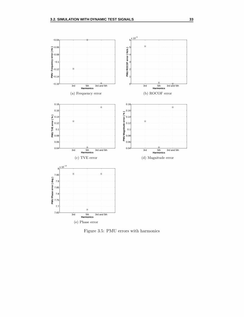
3.1.4 Simulation with harmonic distortion
In harmonic distortion test, the IEEE standard requires a maximum TVEof 1 %, a maximum FE of 0.025 Hz, and a maximum RFE of 6 Hz/s forPMU class M and reporting rate 50 frames/s [1].
The test signals contain the 3rd harmonic, 5th harmonic and 3rd and 5th
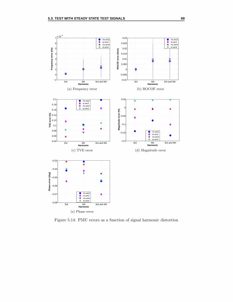
harmonics. PMU errors are shown in Figure 3.5. ROCOF and PhaE arealmost zero. FE, MagE, and TVE of these test signals are much higherthan those of other steady state test signals. MagE and TVE are still farbelow their limits in the standard while FE has exceeded its requirement.The maximum FE is -0.04 Hz with the signal containing the 5th harmonic(Figure 3.5a). The signal containing both the 3rd and 5th harmonics causeshighest MagE (0.17 %), TVE (approximately 0.17 %), and PhaE (7.96∗20−13
deg) while signal containing only the 3rd harmonic causes less errors thanthose of signal containing both the 3rd and 5th harmonics and more errorsthan those of signal containing only the 5th harmonic.
3.2. SIMULATION WITH DYNAMIC TEST SIGNALS 31
0 50 100 150−0.5
0
0.5
1
1.5
2
2.5
3
3.5x 10
−8
Percentage of nominal magnitude ( % )
PM
U F
requ
ency
err
or (
Hz
)
CurrentVoltage
(a) Frequency error
0 50 100 1500
1
2
3
4
5
6
7x 10
−7
Percentage of nominal magnitude ( % )
PM
U R
OC
OF
err
or (
Hz/
s )
CurrentVoltage
(b) ROCOF error
0 50 100 1500
0.5
1
1.5
2
2.5
3
3.5x 10
−8
Percent of nominal magnitude ( % )
PM
U T
VE
err
or (
% )
CurrentVoltage
(c) TVE error
0 50 100 150−2
0
2
4
6
8
10
12
14x 10
−9
Percentage of nominal magnitude ( % )
PM
U M
agni
tude
err
or (
% )
CurrentVoltage
(d) Magnitude error
Figure 3.3: PMU errors with signal magnitudes
3.2 Simulation with dynamic test signals
All dynamic test signals mentioned in part 2.2.2 will be applied for esti-mating PMU performance under such dynamic conditions as modulation,frequency ramp or step change in magnitude and phase angle. The ex-pected simulation results should meet the requirements for dynamic tests,PMU class M and reporting rate 50 frames/s in the standard. Regardingmodulated test, a maximum TVE of 3 %, a maximum FE of 0.3 Hz, and amaximum RFE of 30 Hz/s are required. As for frequency ramp test, TVEshould be less than 3 %, FE should be less than 0.005 Hz, and RFE shouldnot be more than 0.1 Hz/s. For step change in magnitude and phase test,the standard requires a maximum delay time of 1/(4*Fs) or 5 ms, a maxi-mum overshoot of 10 % of step magnitude, a maximum TVE response time
3.2. SIMULATION WITH DYNAMIC TEST SIGNALS 32
−200 −100 0 100 2000
0.2
0.4
0.6
0.8
1x 10
−4
Phase angle ( deg )
PM
U F
requ
ency
err
or (
Hz
)
(a) Frequency error
−200 −100 0 100 2000
0.2
0.4
0.6
0.8
1x 10
−4
Phase angle ( deg )
PM
U R
OC
OF
err
or (
Hz/
s )
(b) ROCOF error
−200 −100 0 100 2000
0.2
0.4
0.6
0.8
1x 10
−4
Phase angle ( deg )
PM
U T
VE
err
or (
% )
(c) TVE error
−200 −100 0 100 2000
0.2
0.4
0.6
0.8
1x 10
−4
Phase angle ( deg )
PM
U P
hase
err
or (
deg
)
(d) Phase error
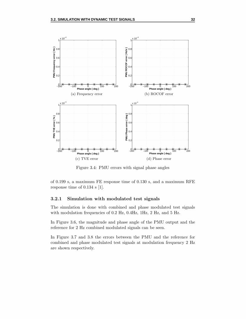
Figure 3.4: PMU errors with signal phase angles
of 0.199 s, a maximum FE response time of 0.130 s, and a maximum RFEresponse time of 0.134 s [1].
3.2.1 Simulation with modulated test signals
The simulation is done with combined and phase modulated test signalswith modulation frequencies of 0.2 Hz, 0.4Hz, 1Hz, 2 Hz, and 5 Hz.
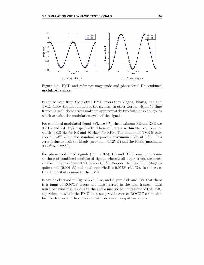
In Figure 3.6, the magnitude and phase angle of the PMU output and thereference for 2 Hz combined modulated signals can be seen.
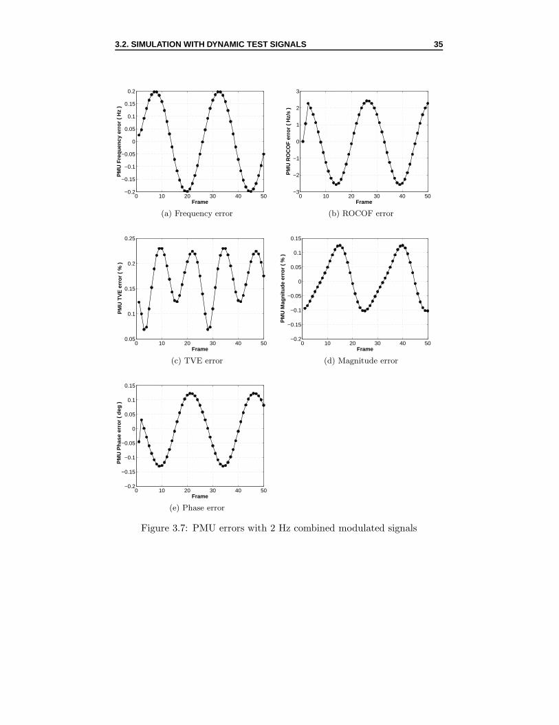
In Figure 3.7 and 3.8 the errors between the PMU and the reference forcombined and phase modulated test signals at modulation frequency 2 Hzare shown respectively.
3.2. SIMULATION WITH DYNAMIC TEST SIGNALS 33
3rd 5th 3rd and 5th−0.16
−0.14
−0.12
−0.1
−0.08
−0.06
−0.04
Harmonics
PM
U F
requ
ency
err
or (
Hz
)
(a) Frequency error
3rd 5th 3rd and 5th0
1
2
3
4
5
6x 10
−9
Harmonics
PM
U R
OC
OF
err
or (
Hz/
s )
(b) ROCOF error
3rd 5th 3rd and 5th0.04
0.06
0.08
0.1
0.12
0.14
0.16
0.18
Harmonics
PM
U T
VE
err
or (
% )
(c) TVE error
3rd 5th 3rd and 5th0.04
0.06
0.08
0.1
0.12
0.14
0.16
0.18
Harmonics
PM
U M
agni
tude
err
or (
% )
(d) Magnitude error
3rd 5th 3rd and 5th7.65
7.7
7.75
7.8
7.85
7.9
7.95
8x 10
−13
Harmonics
PM
U P
hase
err
or (
deg
)
(e) Phase error
Figure 3.5: PMU errors with harmonics
3.2. SIMULATION WITH DYNAMIC TEST SIGNALS 34
0 0.2 0.4 0.6 0.8 11.25
1.3
1.35
1.4
1.45
1.5
1.55
1.6
1.65
Time
Mag
nitu
de
PMUref
(a) Magnitudes
0 0.2 0.4 0.6 0.8 1−6
−4
−2
0
2
4
6
Time
Pha
se a
ngle
( d
eg )
PMUref
(b) Phase angles
Figure 3.6: PMU and reference magnitude and phase for 2 Hz combinedmodulated signals
It can be seen from the plotted PMU errors that MagEs, PhaEs, FEs andTVEs follow the modulation of the signals. In other words, within 50 timeframes (1 sec), these errors make up approximately two full sinusoidal cycleswhich are also the modulation cycle of the signals.
For combined modulated signals (Figure 3.7), the maximum FE and RFE are0.2 Hz and 2.4 Hz/s respectively. These values are within the requirement,which is 0.3 Hz for FE and 30 Hz/s for RFE. The maximum TVE is onlyabout 0.23% while the standard requires a maximum TVE of 3 %. Thiserror is due to both the MagE (maximum 0.125 %) and the PhaE (maximum0.1230 or 0.22 %).
For phase modulated signals (Figure 3.8), FE and RFE remain the sameas those of combined modulated signals whereas all other errors are muchsmaller. The maximum TVE is now 0.1 %. Besides, the maximum MagE isquite small (0.001 %) and maximum PhaE is 0.05780 (0.1 %). In this case,PhaE contributes more to the TVE.
It can be observed in Figure 3.7b, 3.7e, and Figure 3.8b and 3.8e that thereis a jump of ROCOF errors and phase errors in the first frames. Thisweird behavior may be due to the above mentioned limitations of the PMUalgorithm, in which the PMU does not provide correct ROCOF estimationfor first frames and has problem with response to rapid variations.
3.2. SIMULATION WITH DYNAMIC TEST SIGNALS 35
0 10 20 30 40 50−0.2
−0.15
−0.1
−0.05
0
0.05
0.1
0.15
0.2
Frame
PM
U F
requ
ency
err
or (
Hz
)
(a) Frequency error
0 10 20 30 40 50−3
−2
−1
0
1
2
3
Frame
PM
U R
OC
OF
err
or (
Hz/
s )
(b) ROCOF error
0 10 20 30 40 500.05
0.1
0.15
0.2
0.25
Frame
PM
U T
VE
err
or (
% )
(c) TVE error
0 10 20 30 40 50−0.2
−0.15
−0.1
−0.05
0
0.05
0.1
0.15
Frame
PM
U M
agni
tude
err
or (
% )
(d) Magnitude error
0 10 20 30 40 50−0.2
−0.15
−0.1
−0.05
0
0.05
0.1
0.15
Frame
PM
U P
hase
err
or (
deg
)
(e) Phase error
Figure 3.7: PMU errors with 2 Hz combined modulated signals
3.2. SIMULATION WITH DYNAMIC TEST SIGNALS 36
0 10 20 30 40 50−0.2
−0.15
−0.1
−0.05
0
0.05
0.1
0.15
0.2
Frame
PM
U F
requ
ency
err
or (
Hz
)
(a) Frequency error
0 10 20 30 40 50−3
−2
−1
0
1
2
3
Frame
PM
U R
OC
OF
err
or (
Hz/
s )
(b) ROCOF error
0 10 20 30 40 500
0.02
0.04
0.06
0.08
0.1
0.12
Frame
PM
U T
VE
err
or (
% )
(c) TVE error
10 20 30 40 50−0.01
−0.005
0
0.005
0.01
Frame
PM
U M
agni
tude
err
or (
% )
(d) Magnitude error
0 10 20 30 40 50−0.06
−0.04
−0.02
0
0.02
0.04
0.06
Frame
PM
U P
hase
err
or (
deg
)
(e) Phase error
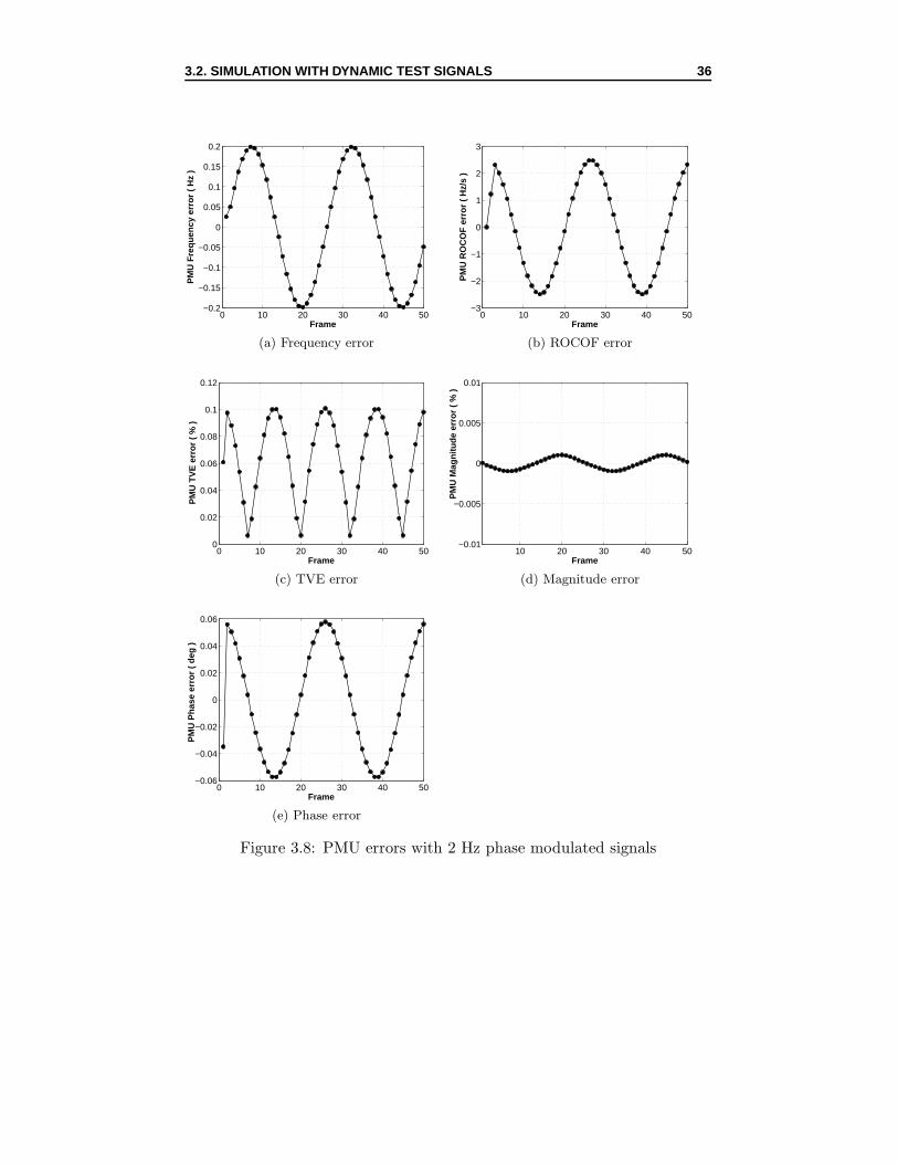
Figure 3.8: PMU errors with 2 Hz phase modulated signals
3.2. SIMULATION WITH DYNAMIC TEST SIGNALS 37
The highest modulation frequency that the PMU algorithm could keep allerrors within the limits is 3 Hz. Beyond this frequency, TVE is still farbelow its standard but FE and RFE have exceeded their limits.
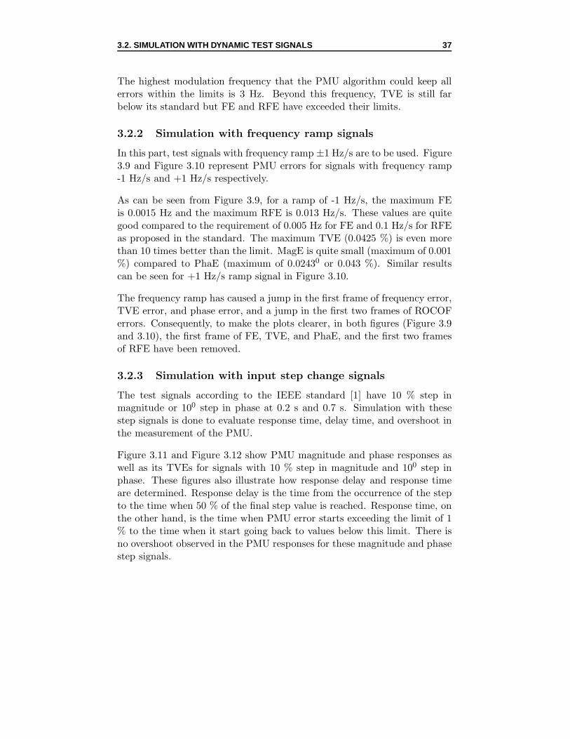
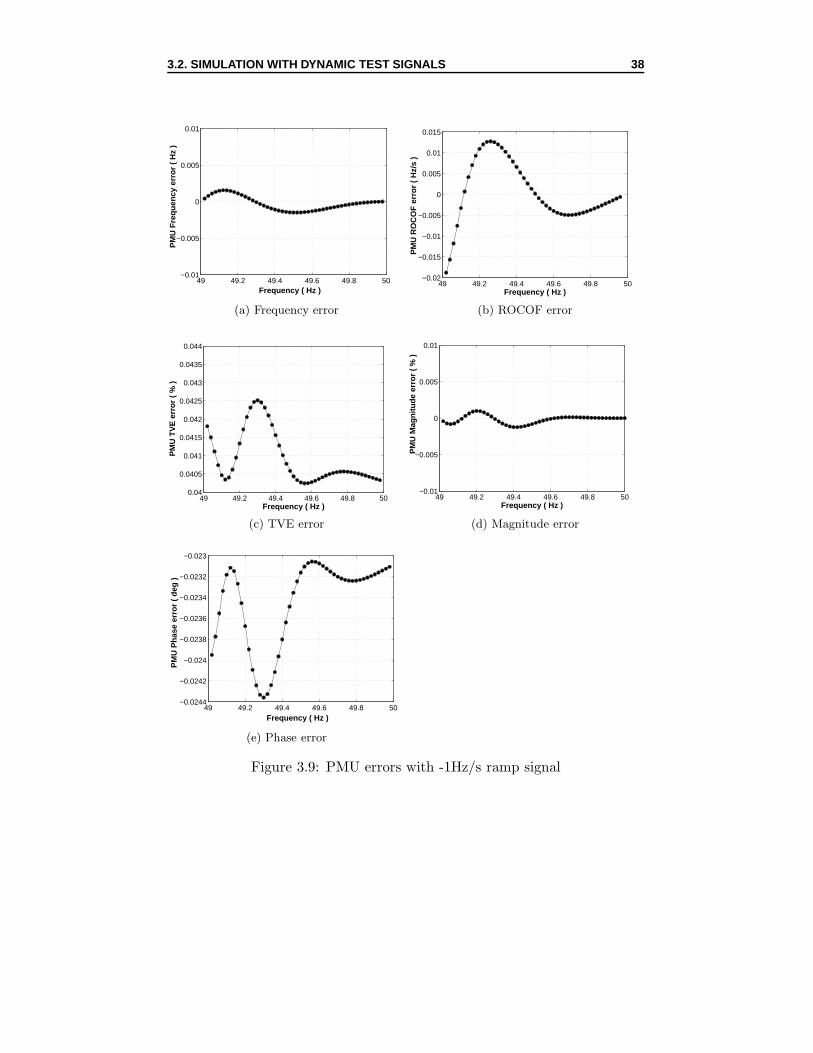
3.2.2 Simulation with frequency ramp signals
In this part, test signals with frequency ramp ±1 Hz/s are to be used. Figure3.9 and Figure 3.10 represent PMU errors for signals with frequency ramp-1 Hz/s and +1 Hz/s respectively.
As can be seen from Figure 3.9, for a ramp of -1 Hz/s, the maximum FEis 0.0015 Hz and the maximum RFE is 0.013 Hz/s. These values are quitegood compared to the requirement of 0.005 Hz for FE and 0.1 Hz/s for RFEas proposed in the standard. The maximum TVE (0.0425 %) is even morethan 10 times better than the limit. MagE is quite small (maximum of 0.001%) compared to PhaE (maximum of 0.02430 or 0.043 %). Similar resultscan be seen for +1 Hz/s ramp signal in Figure 3.10.
The frequency ramp has caused a jump in the first frame of frequency error,TVE error, and phase error, and a jump in the first two frames of ROCOFerrors. Consequently, to make the plots clearer, in both figures (Figure 3.9and 3.10), the first frame of FE, TVE, and PhaE, and the first two framesof RFE have been removed.
3.2.3 Simulation with input step change signals
The test signals according to the IEEE standard [1] have 10 % step inmagnitude or 100 step in phase at 0.2 s and 0.7 s. Simulation with thesestep signals is done to evaluate response time, delay time, and overshoot inthe measurement of the PMU.
Figure 3.11 and Figure 3.12 show PMU magnitude and phase responses aswell as its TVEs for signals with 10 % step in magnitude and 100 step inphase. These figures also illustrate how response delay and response timeare determined. Response delay is the time from the occurrence of the stepto the time when 50 % of the final step value is reached. Response time, onthe other hand, is the time when PMU error starts exceeding the limit of 1% to the time when it start going back to values below this limit. There isno overshoot observed in the PMU responses for these magnitude and phasestep signals.
3.2. SIMULATION WITH DYNAMIC TEST SIGNALS 38
49 49.2 49.4 49.6 49.8 50−0.01
−0.005
0
0.005
0.01
Frequency ( Hz )
PM
U F
requ
ency
err
or (
Hz
)
(a) Frequency error
49 49.2 49.4 49.6 49.8 50−0.02
−0.015
−0.01
−0.005
0
0.005
0.01
0.015
Frequency ( Hz )
PM
U R
OC
OF
err
or (
Hz/
s )
(b) ROCOF error
49 49.2 49.4 49.6 49.8 500.04
0.0405
0.041
0.0415
0.042
0.0425
0.043
0.0435
0.044
Frequency ( Hz )
PM
U T
VE
err
or (
% )
(c) TVE error
49 49.2 49.4 49.6 49.8 50−0.01
−0.005
0
0.005
0.01
Frequency ( Hz )
PM
U M
agni
tude
err
or (
% )
(d) Magnitude error
49 49.2 49.4 49.6 49.8 50−0.0244
−0.0242
−0.024
−0.0238
−0.0236
−0.0234
−0.0232
−0.023
Frequency ( Hz )
PM
U P
hase
err
or (
deg
)
(e) Phase error
Figure 3.9: PMU errors with -1Hz/s ramp signal
3.2. SIMULATION WITH DYNAMIC TEST SIGNALS 39
50 50.2 50.4 50.6 50.8 51−0.01
−0.005
0
0.005
0.01
Frequency ( Hz )
PM
U F
requ
ency
err
or (
Hz
)
(a) Frequency error
50 50.2 50.4 50.6 50.8 51−0.02
−0.015
−0.01
−0.005
0
0.005
0.01
Frequency ( Hz )
PM
U R
OC
OF
err
or (
Hz/
s )
(b) ROCOF error
50 50.2 50.4 50.6 50.8 510.038
0.039
0.04
0.041
0.042
0.043
0.044
0.045
Frequency ( Hz )
PM
U T
VE
err
or (
% )
(c) TVE error
50 50.2 50.4 50.6 50.8 51−0.01
−0.005
0
0.005
0.01
Frequency ( Hz )
PM
U M
agni
tude
err
or (
% )
(d) Magnitude error
50 50.2 50.4 50.6 50.8 510.022
0.0225
0.023
0.0235
0.024
0.0245
0.025
0.0255
Frequency ( Hz )
PM
U P
hase
err
or (
deg
)
(e) Phase error
Figure 3.10: PMU errors with +1Hz/s ramp signal
3.2. SIMULATION WITH DYNAMIC TEST SIGNALS 40
0 0.2 0.4 0.6 0.8 11.4
1.42
1.44
1.46
1.48
1.5
1.52
1.54
1.56
Time (s)
Sig
nal m
agni
tude
Response delay
50% of the step value
(a) Response delay
0 10 20 30 40 500
1
2
3
4
5
Frame
PM
U T
VE
err
or (
% )
Response time
(b) Response time
Figure 3.11: PMU responses for magnitude step signal
0 0.2 0.4 0.6 0.8 10
2
4
6
8
10
X: 0.2Y: 5.119
Time (s)
Sig
nal p
hase
ang
le (
deg
)
50% of the step value
Response delay
(a) Response delay
0 10 20 30 40 500
2
4
6
8
10
Frame
PM
U T
VE
err
or (
% )
Response time
(b) Response time
Figure 3.12: PMU responses for phase step signal
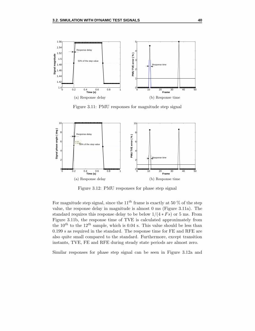
For magnitude step signal, since the 11th frame is exactly at 50 % of the stepvalue, the response delay in magnitude is almost 0 ms (Figure 3.11a). Thestandard requires this response delay to be below 1/(4 ∗ Fs) or 5 ms. FromFigure 3.11b, the response time of TVE is calculated approximately fromthe 10th to the 12th sample, which is 0.04 s. This value should be less than0.199 s as required in the standard. The response time for FE and RFE arealso quite small compared to the standard. Furthermore, except transitioninstants, TVE, FE and RFE during steady state periods are almost zero.
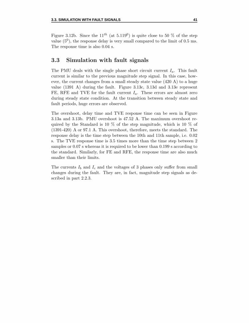
Similar responses for phase step signal can be seen in Figure 3.12a and
3.3. SIMULATION WITH FAULT SIGNALS 41
Figure 3.12b. Since the 11th (at 5.1190) is quite close to 50 % of the stepvalue (50), the response delay is very small compared to the limit of 0.5 ms.The response time is also 0.04 s.
3.3 Simulation with fault signals
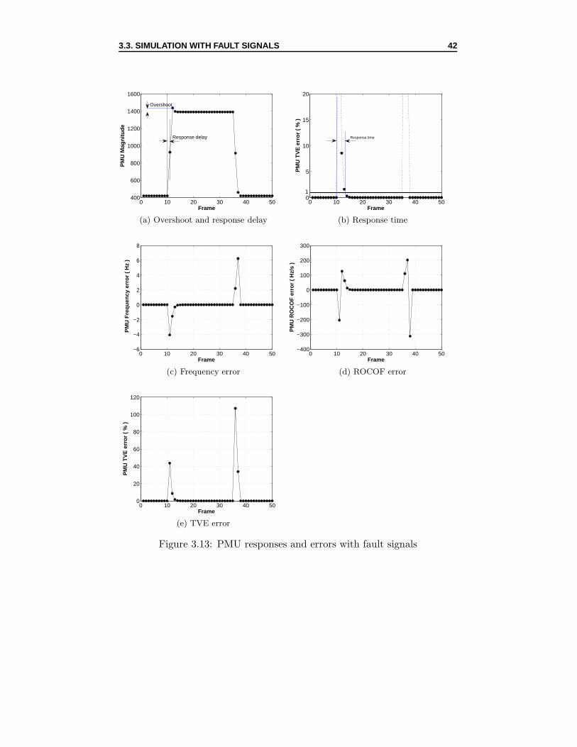
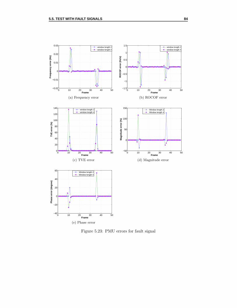
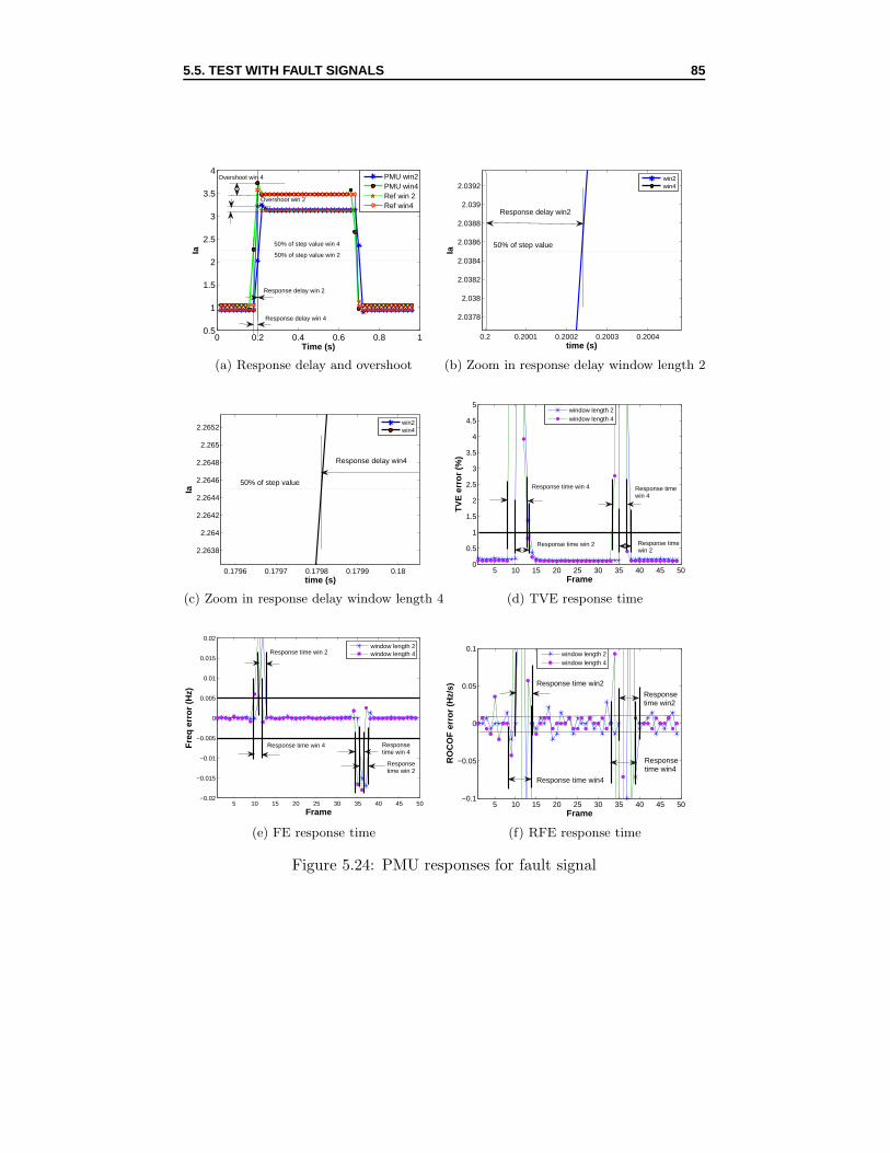
The PMU deals with the single phase short circuit current Ia. This faultcurrent is similar to the previous magnitude step signal. In this case, how-ever, the current changes from a small steady state value (420 A) to a hugevalue (1391 A) during the fault. Figure 3.13c, 3.13d and 3.13e representFE, RFE and TVE for the fault current Ia. These errors are almost zeroduring steady state condition. At the transition between steady state andfault periods, huge errors are observed.
The overshoot, delay time and TVE response time can be seen in Figure3.13a and 3.13b. PMU overshoot is 47.52 A. The maximum overshoot re-quired by the Standard is 10 % of the step magnitude, which is 10 % of(1391-420) A or 97.1 A. This overshoot, therefore, meets the standard. Theresponse delay is the time step between the 10th and 11th sample, i.e. 0.02s. The TVE response time is 3.5 times more than the time step between 2samples or 0.07 s whereas it is required to be lower than 0.199 s according tothe standard. Similarly, for FE and RFE, the response time are also muchsmaller than their limits.
The currents Ib and Ic and the voltages of 3 phases only suffer from smallchanges during the fault. They are, in fact, magnitude step signals as de-scribed in part 2.2.3.
3.3. SIMULATION WITH FAULT SIGNALS 42
0 10 20 30 40 50400
600
800
1000
1200
1400
1600
Frame
PM
U M
agni
tude
Response delay
Overshoot
(a) Overshoot and response delay
0 10 20 30 40 500
5
10
15
20
Frame
PM
U T
VE
err
or (
% )
Response time
1
(b) Response time
0 10 20 30 40 50−6
−4
−2
0
2
4
6
8
Frame
PM
U F
requ
ency
err
or (
Hz
)
(c) Frequency error
0 10 20 30 40 50−400
−300
−200
−100
0
100
200
300
Frame
PM
U R
OC
OF
err
or (
Hz/
s )
(d) ROCOF error
0 10 20 30 40 500
20
40
60
80
100
120
Frame
PM
U T
VE
err
or (
% )
(e) TVE error
Figure 3.13: PMU responses and errors with fault signals
Chapter 4
PMU test setup
4.1 Test principle
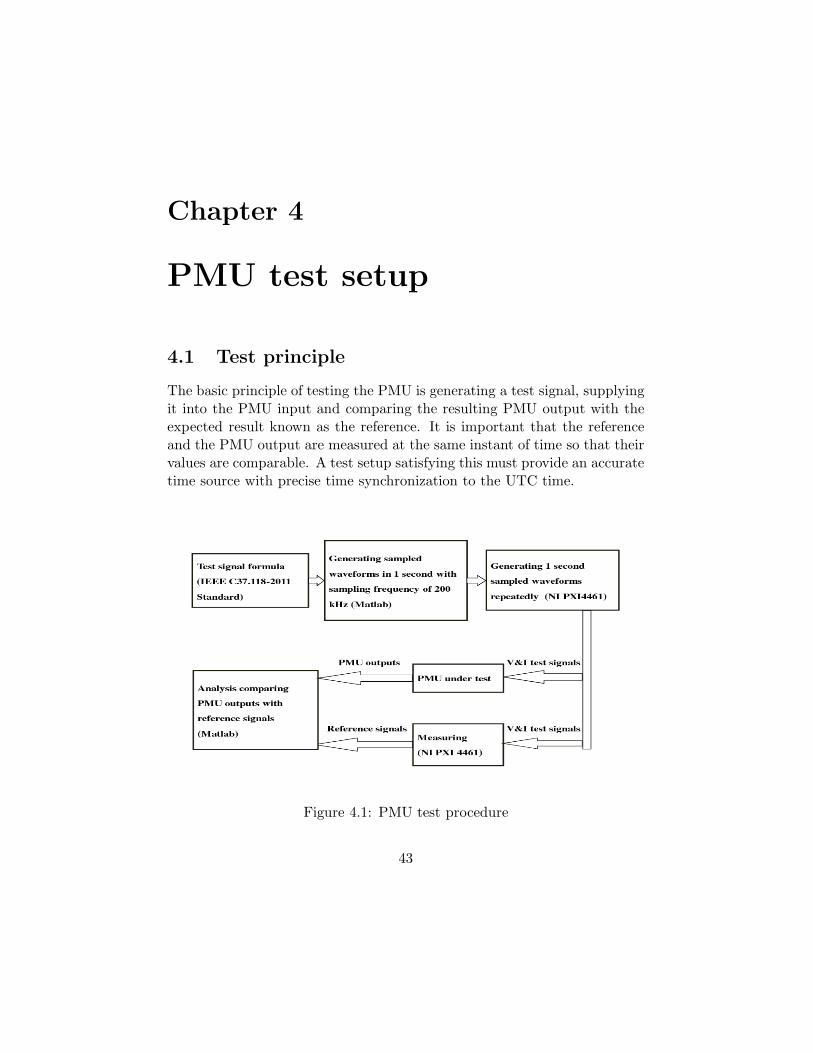
The basic principle of testing the PMU is generating a test signal, supplyingit into the PMU input and comparing the resulting PMU output with theexpected result known as the reference. It is important that the referenceand the PMU output are measured at the same instant of time so that theirvalues are comparable. A test setup satisfying this must provide an accuratetime source with precise time synchronization to the UTC time.
Figure 4.1: PMU test procedure
43
4.2. TEST SETUP 44
According to the C37.118-2011 Standard [1], it is highly recommended that atime source should reliably provide time, frequency, and frequency stabilityat least 10 times better than those values corresponding to 1 % TVE, whichare ±31 µs for time and 0.1 mHz for frequency, respectively [1].
The test procedure is summarized as in Figure 4.1.
4.2 Test setup
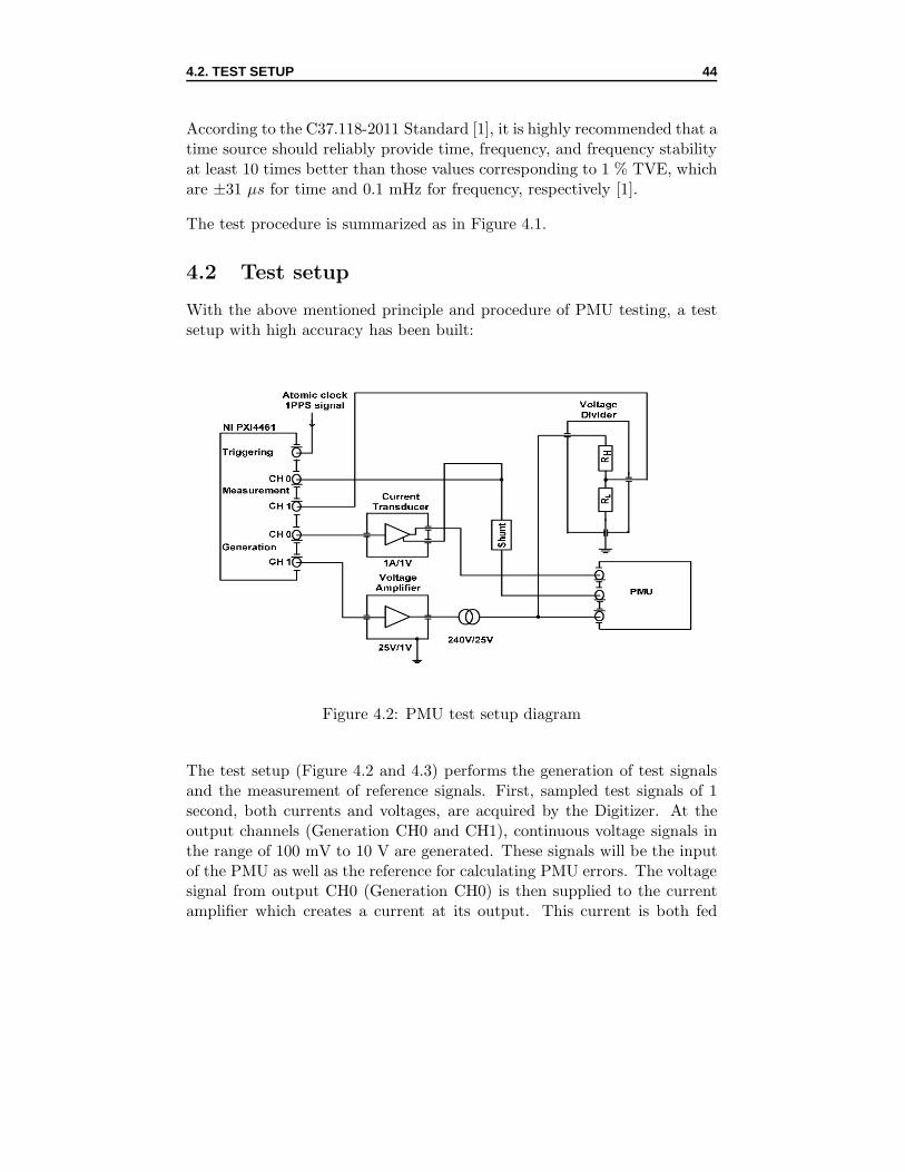
With the above mentioned principle and procedure of PMU testing, a testsetup with high accuracy has been built:
Figure 4.2: PMU test setup diagram
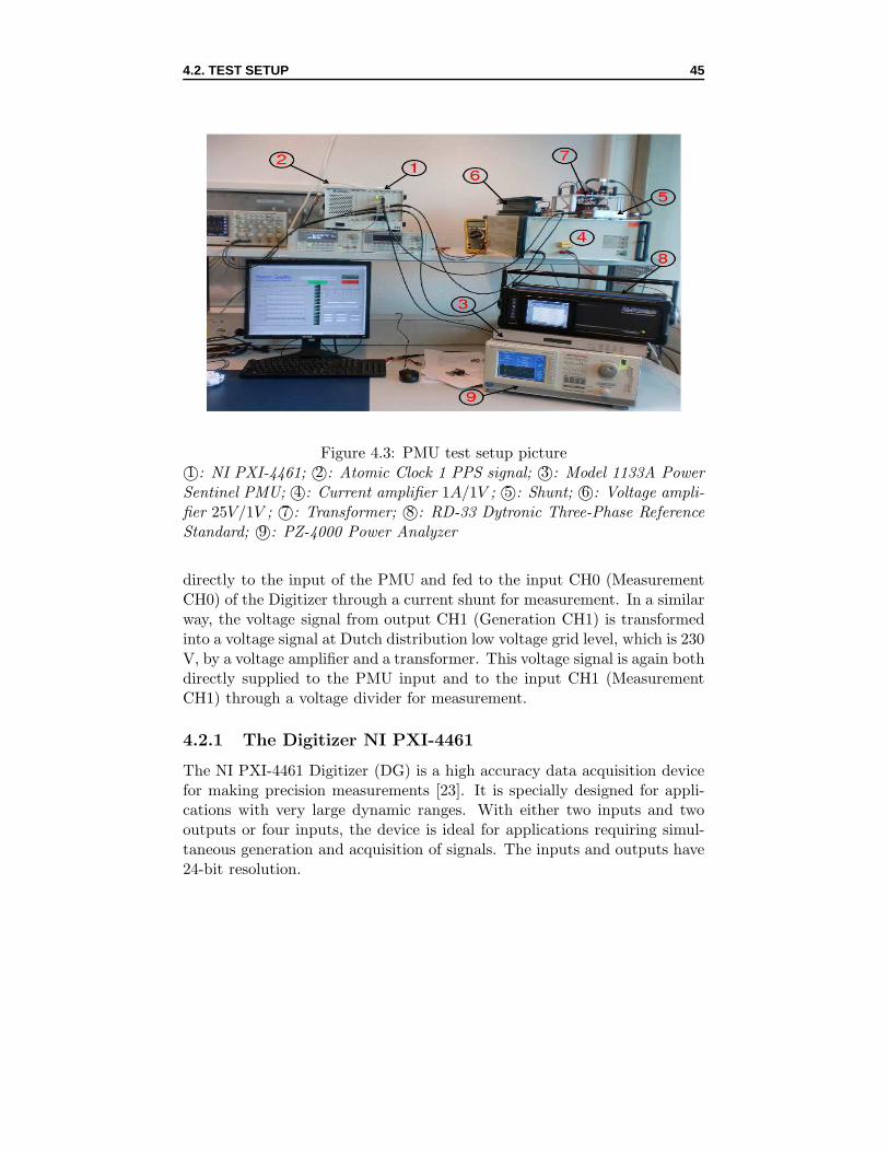
The test setup (Figure 4.2 and 4.3) performs the generation of test signalsand the measurement of reference signals. First, sampled test signals of 1second, both currents and voltages, are acquired by the Digitizer. At theoutput channels (Generation CH0 and CH1), continuous voltage signals inthe range of 100 mV to 10 V are generated. These signals will be the inputof the PMU as well as the reference for calculating PMU errors. The voltagesignal from output CH0 (Generation CH0) is then supplied to the currentamplifier which creates a current at its output. This current is both fed
directly to the input of the PMU and fed to the input CH0 (MeasurementCH0) of the Digitizer through a current shunt for measurement. In a similarway, the voltage signal from output CH1 (Generation CH1) is transformedinto a voltage signal at Dutch distribution low voltage grid level, which is 230V, by a voltage amplifier and a transformer. This voltage signal is again bothdirectly supplied to the PMU input and to the input CH1 (MeasurementCH1) through a voltage divider for measurement.
4.2.1 The Digitizer NI PXI-4461
The NI PXI-4461 Digitizer (DG) is a high accuracy data acquisition devicefor making precision measurements [23]. It is specially designed for appli-cations with very large dynamic ranges. With either two inputs and twooutputs or four inputs, the device is ideal for applications requiring simul-taneous generation and acquisition of signals. The inputs and outputs have24-bit resolution.
4.2. TEST SETUP 46
In the PMU test setup, the DG is used for both generating and measuringtest signals. The generating function is performed through D/A converterswith two high-fidelity analog output channels (Generation CH0 and CH1).These analog output channels have a voltage range of ±100 mV to 10V andan update rate up to 204.8 kS/s. During the PMU tests, when a 1sec 200kHz sampled test signal is acquired at the input channels, a 1 Vrms voltagesignal will be generated repeatedly at the analog output channels. The mea-surement is done through 24-bit resolution A/D converters with two analoginput channels (Measurement CH0 and CH1). The voltage range of thesechannels is ±316 mV to 42.4V and the update rate can also reach 204.8kS/s.
The analog output channels have analog and digital anti-imaging filters.Analog filters will remove unexpected interharmonic components generatedwhen an analog signal is produced from digital data. Digital filters will limitthe bandwidth of the output signal to half the original conversion rate, thusreject images caused by the 8-times oversampling process. The generatedsignals, as a result, are low-distortion, low noise and flat-frequency.
Similarly, there are both analog and digital filters in the analog inputs forantialiasing. Analog filters help filter out from input signals all frequencycomponents beyond the range of the A/D converters while digital filtersautomatically adjust their cut-off frequency to remove any frequency com-ponents above half the programmed sampling rate.
The DG also provides analog and digital triggering channel for signal acqui-sition.
4.2.2 The amplifiers
There are two amplifiers in the test setup, i.e the current amplifier and thevoltage amplifier. The current amplifier is used for transforming a voltagesignal into a current signal with the transforming ratio of 1A/1V . Thevoltage amplifier increases voltage signals to higher values with an amplify-ing ratio of 25V/1V . However, the exact behavior of the amplifiers is notrelevant since we are measuring the signal applied to the PMU with thereference system.
In the test setup, a 240V/25V transformer is also employed to convert thevoltage signal at the output of the voltage amplifier to the Dutch distributionlow voltage grid level.
4.2. TEST SETUP 47
4.2.3 The current shunt and the voltage divider
The current shunt is used for converting current signals to voltage levels ofthe Digitizer analog input channels. It is a low resistance operating by theprinciple of Ohm’s law (V = R ∗ I) and AC or DC current can be measuredfrom the voltage drop created by the current flowing across it. The nominalvalue of the current shunt in the PMU test setup is 0.09 Ohm but the realvalue after calibration is 0.089594 Ohm.
Both analog input channels of the DG are not designed to directly measurevoltages and currents up to levels needed for a power measurement. For thisreason, voltages need to be scaled down to smaller values which are suitablefor the DG to measure. This could be done with a resistive voltage divider.The nominal divider ratio of the voltage divider is 100. In fact, its real ratioafter calibration is 101.035.
4.2.4 The PMU under test
The PMU to be tested is the Model 1133A Power Sentinel provided byArbiter Systems [24]. It consists of GPS receiver and synchronization, volt-age and current inputs, programmable-gain amplifier, multiplexers and A/Dconverter, digital signal processor, display and keyboard, I/O functions, andpower supply.
With a twelve-channel GPS receiver, accurate time of up to a fraction of amicrosecond anywhere in the world is made by comparing an internal 10-MHz crystal oscillator to a 1-PPS output of the GPS receiver.
The PMU offers a wide range of window functions to optimize phasor out-puts for different applications. The windowing function includes EstimatorAlgorithm and Window Length in cycles. This window function behaves asa low pass filter which filters out higher frequency components.
The PMU measures voltage or current by making a number of separatemeasurements per second, depending on the reporting rate, of the squareof the voltage or current samples. The square root of the resulting sum isproportional to the rms voltage or current value during that measurementinterval.
The PMU performs a fast Fourier transform (FFT) of the windowed voltageand current samples to calculate phase angle and frequency. Phase anglesare calculated from the relationship between the real and imaginary parts
4.3. TIME SOURCE 48
of the fundamental-frequency bin of the FFT. The phase measurements arethen compared to determine phase angle between voltages and currents orbetween any two voltages or currents. With the use of GPS synchronization,phase angle measurements are made comparable between different PMUs.Frequency is measured by taking the difference in phase angle between sub-sequent measurements based on f = dϕ/dt.
Phasor data are formatted and output in accordance with IEEE Synchropha-sor standard C37.118. A phasor consists of the real and imaginary compo-nents of voltage or current magnitude at a particular point in a power dis-tribution system, along with suitable time synchronization fields and otherinformation. This information is in real time, and is based on the measuredfundamental voltage, current, and phase angle described above.
In addition to phasor measurements, the PMU could also perform energyand power measurements, power quality measurements such as harmonicmeasurements, power interruptions and flicker.
The PMU is connected to PC through a software named PSCSV providedby the vendor. Besides, the PMU has been selected to be of class M withthe reporting rate of 50 frames/s during all tests, thus it should satisfy thestandards for class M at 50 frames/s.
The three phase current inputs of the PMU are connected in series and thethree phase voltage inputs are connected in parallel so that the performanceof all three phases of the PMU could be evaluated.
4.3 Time source
In order to evaluate the measurement quality of the PMU through TVE, FEand RFE, the reference phasors have to be measured at the same instantof time as the estimated phasors of the PMU. Therefore, one of the mostimportant issues in PMU testing is to provide a reliable time source withvery high accuracy with respect to the UTC time. This can be done by syn-chronizing both the PMU measurements and the measurements of referencephasors to the UTC time.
The PMU is synchronized by a built-in GPS satellite receiver to within 1µs of the UTC time. As a result, each PMU measurement is assigned atime tag indicating the UTC time at which the measurement is done. Areporting rate of 50 frames/s is chosen for the PMU under test, thus each
4.3. TIME SOURCE 49
measurement of the PMU has 50 data frames in 1 second.
To synchronize the measurement of the reference signals to the UTC time,an atomic clock 1 PPS signal is supplied through a 50 Ohm impedance tothe triggering channel of the DG. This 1 PPS signal comes from the cesiumatomic clock laboratory of VSL. The atomic clock provides a time sourcewith an accuracy in the order of several nanoseconds with reference to theUTC time. Every measurement of reference signals is triggered by the 1PPS signal and the time of the PC is recorded as the time at which eachmeasurement is started. Since the PC has been accurately adjusted to theUTC time, the time of each measurement is actually the UTC time.
From the time tag in PMU measurements and the time of reference signalmeasurements, estimated phasors of the PMU and reference phasors at thesame instants of time can be known. The PMU measurement quality canthen be evaluated by calculating TVE, FE and RFE of both phasors.
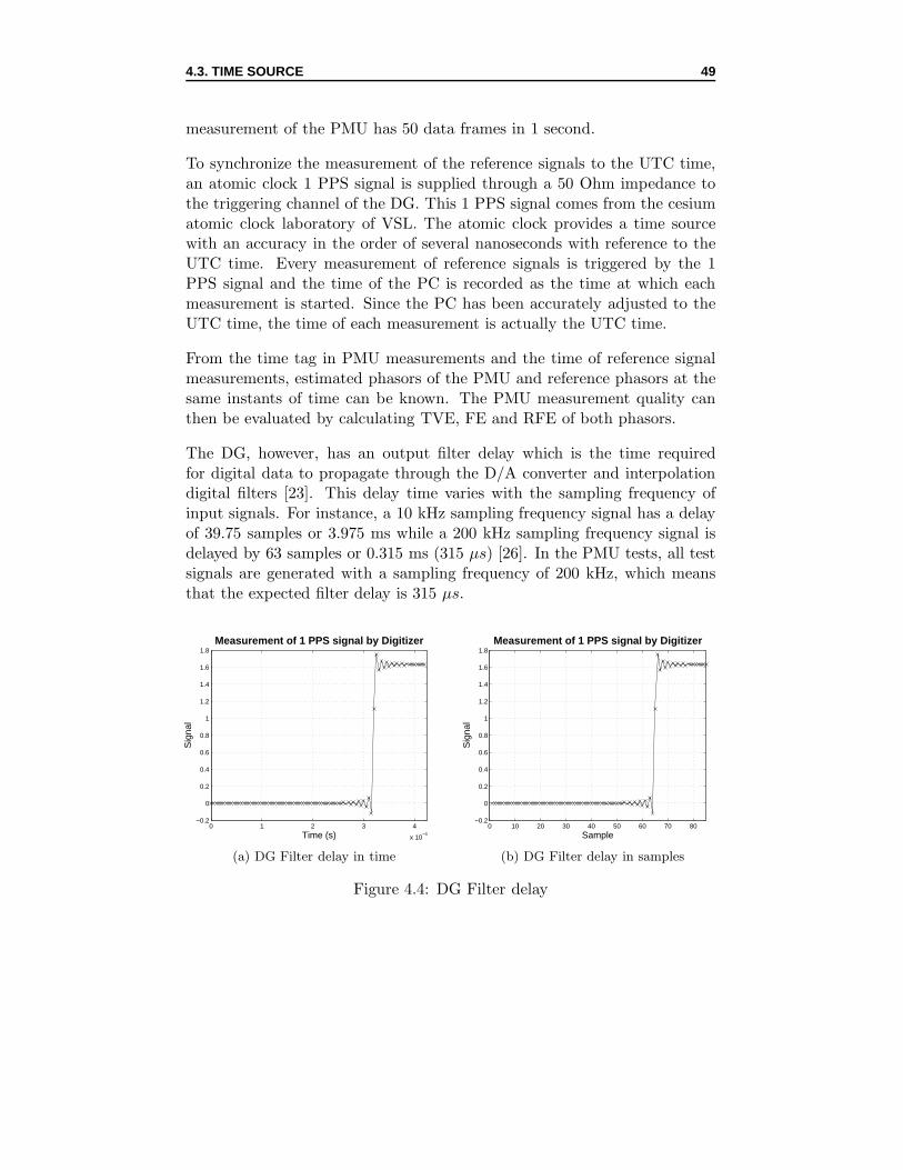
The DG, however, has an output filter delay which is the time requiredfor digital data to propagate through the D/A converter and interpolationdigital filters [23]. This delay time varies with the sampling frequency ofinput signals. For instance, a 10 kHz sampling frequency signal has a delayof 39.75 samples or 3.975 ms while a 200 kHz sampling frequency signal isdelayed by 63 samples or 0.315 ms (315 µs) [26]. In the PMU tests, all testsignals are generated with a sampling frequency of 200 kHz, which meansthat the expected filter delay is 315 µs.
0 1 2 3 4
x 10−4
−0.2
0
0.2
0.4
0.6
0.8
1
1.2
1.4
1.6
1.8
Time (s)
Sig
nal
Measurement of 1 PPS signal by Digitizer
(a) DG Filter delay in time
0 10 20 30 40 50 60 70 80−0.2
0
0.2
0.4
0.6
0.8
1
1.2
1.4
1.6
1.8
Sample
Sig
nal
Measurement of 1 PPS signal by Digitizer
(b) DG Filter delay in samples
Figure 4.4: DG Filter delay
4.3. TIME SOURCE 50
To exactly determine the filter delay of the DG in the test setup, a test on a1 PPS signal is done. In this test, an atomic clock 1 PPS signal is supplied tothe triggering channel of the DG. Another atomic clock 1 PPS signal is fedinto one of the two analog inputs, say, CH0 for measuring. The delay timewill be the time from the first sample of the measured pulse to the samplein the middle of the rising edge of the pulse. The measurement result hasshown an average filter delay of approximately 319 µs (Figure 4.4).
An uncertainty of 3 µs is considered to take into account variations or jitterof the middle point of the signal due to some unknown behavior inside theDG. The filter delay now becomes (319 ± 3) µs. A filter delay of 320 µs or64 samples is then included for all the later PMU tests.
For a particular test, a 200000 samples (1 second) signal is measured 7 timesin 7 seconds, in which the 1 second signal is running continuously and then7 measurements are triggered by consecutive 1 PPS pulses. However, onlythe first 197000 samples, instead of 200000 samples, of the 1 second signalis selected for measuring so that there is time for data transfer between thedigitizer and the PMU. If more samples are taken, the next trigger of the 1PPS signal will be missed. The corresponding PMU measurements, there-fore, should include only 49 instead of 50 frames in 1 second and TVE, FEand RFE will be calculated for these 49 frames.
Chapter 5
PMU test results
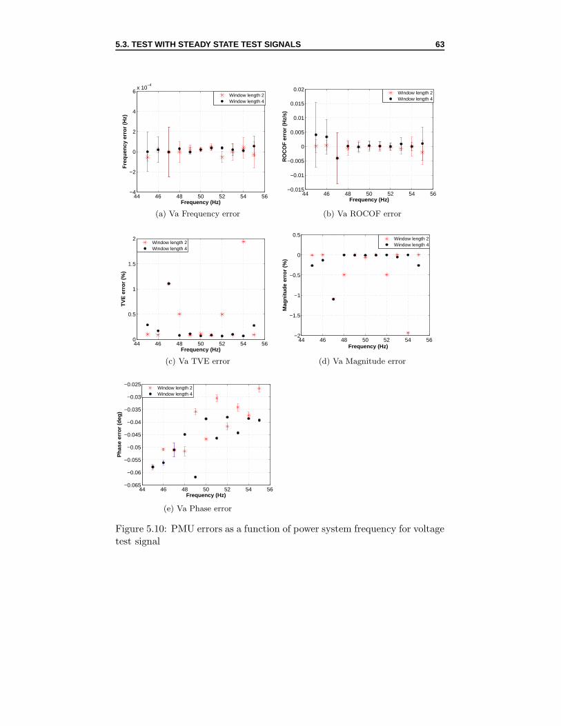
The Model 1133A Power Sentinel PMU is tested using the steady state,dynamic and fault test signals described in chapter 2. The accuracy of thePMU in measuring such basic quantities as magnitude, phase angle andfrequency can be tested through steady state test signals. Dynamic testsignals are used for evaluating the dynamic PMU performance through thevariation of signal magnitude, phase angle and frequency. The PMU mea-surement quality is also tested under fault conditions with the fault signals.
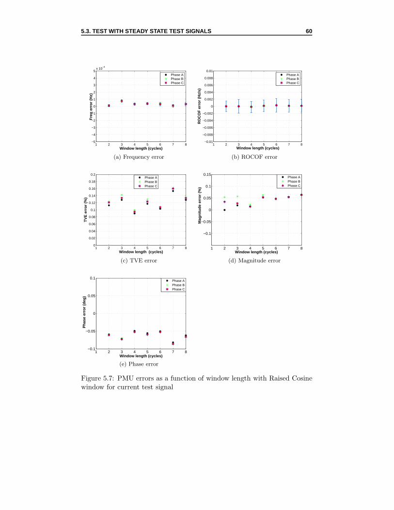
Besides, the PMU provides a wide range of window functions for optimizingphasor outputs for individual applications. This window function consists ofestimator algorithm and window length in cycles [24]. To choose a suitablewindow function for later PMU tests, a test has also been performed ondifferent window functions.
All tests are performed in such procedure and principle as depicted in chap-ter 4. The PMU is tested on both its current and voltage measurementquality. For each test signal, 7 measurements are done. The obtained dataare then analyzed in Matlab under the reporting rate of 50 frames/s. First,the measurements of the PMU are aligned with the measurements of thereference signals on the basis of the time tag in each measurement. Next,the reference data are Discrete Fourier transformed with the use of the Dis-crete Fourier Matlab Simulink block to extract the magnitude and phaseangle of the fundamental signal component. Afterward, the PMU phasorsand reference phasors are compared for determining PMU errors. Theseerrors, including FE, RFE, TVE, MagE and PhaE, are calculated by thefunction TVECalculator in TVECalculator.m. Then, in each time frame,PMU errors of all 7 measurements are averaged to get an average error.
51
5.1. PMU WINDOW FUNCTIONS 52
In each steady state test, the PMU has one value for each error (FE, RFE,TVE, MagE or PhaE) over 50 time frames. This error is resulted from theaverage of the errors over these 50 frames. In dynamic tests, PMU errors arenot averaged over 50 time frames. Instead, they are plotted as a function offrame.
5.1 PMU Window functions
5.1.1 Window function properties
The PMU offers 9 window functions including Rectangular, Raised Cosine,Hann, Hamming, Blackman, Triangular, Flat Top, Kaiser and Nutall 4 Termand 8 window lengths from 1 to 8 cycles. The Discrete Fourier MatlabSimulink block, however, by default, only uses the Rectangular window,which can not be changable, for estimating the reference data.
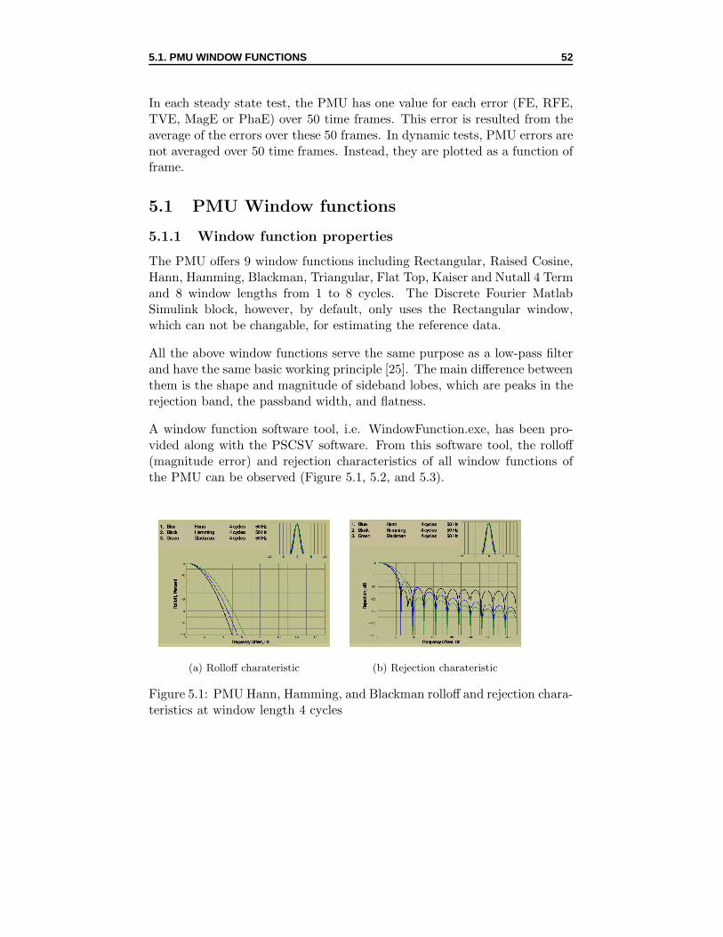
All the above window functions serve the same purpose as a low-pass filterand have the same basic working principle [25]. The main difference betweenthem is the shape and magnitude of sideband lobes, which are peaks in therejection band, the passband width, and flatness.
A window function software tool, i.e. WindowFunction.exe, has been pro-vided along with the PSCSV software. From this software tool, the rolloff(magnitude error) and rejection characteristics of all window functions ofthe PMU can be observed (Figure 5.1, 5.2, and 5.3).
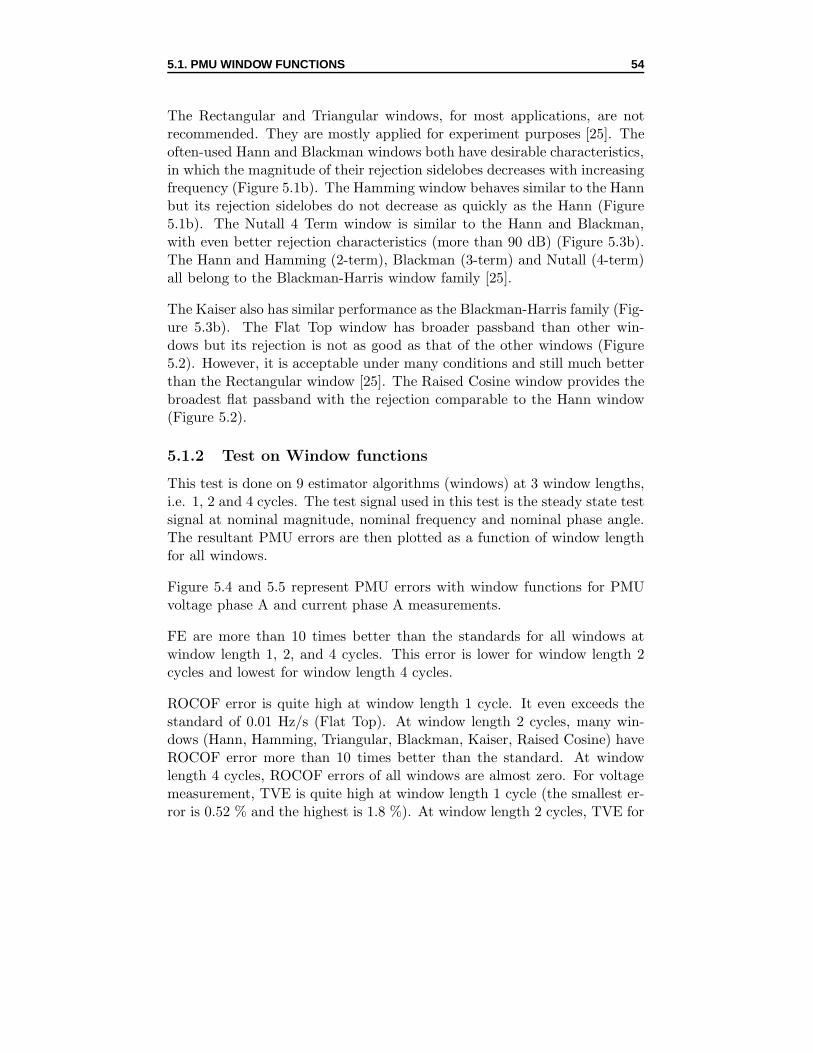
Figure 5.3: PMU Triangular, Kaiser, and Nutall 4 Term rolloff and rejectioncharateristics at window length 4 cycles
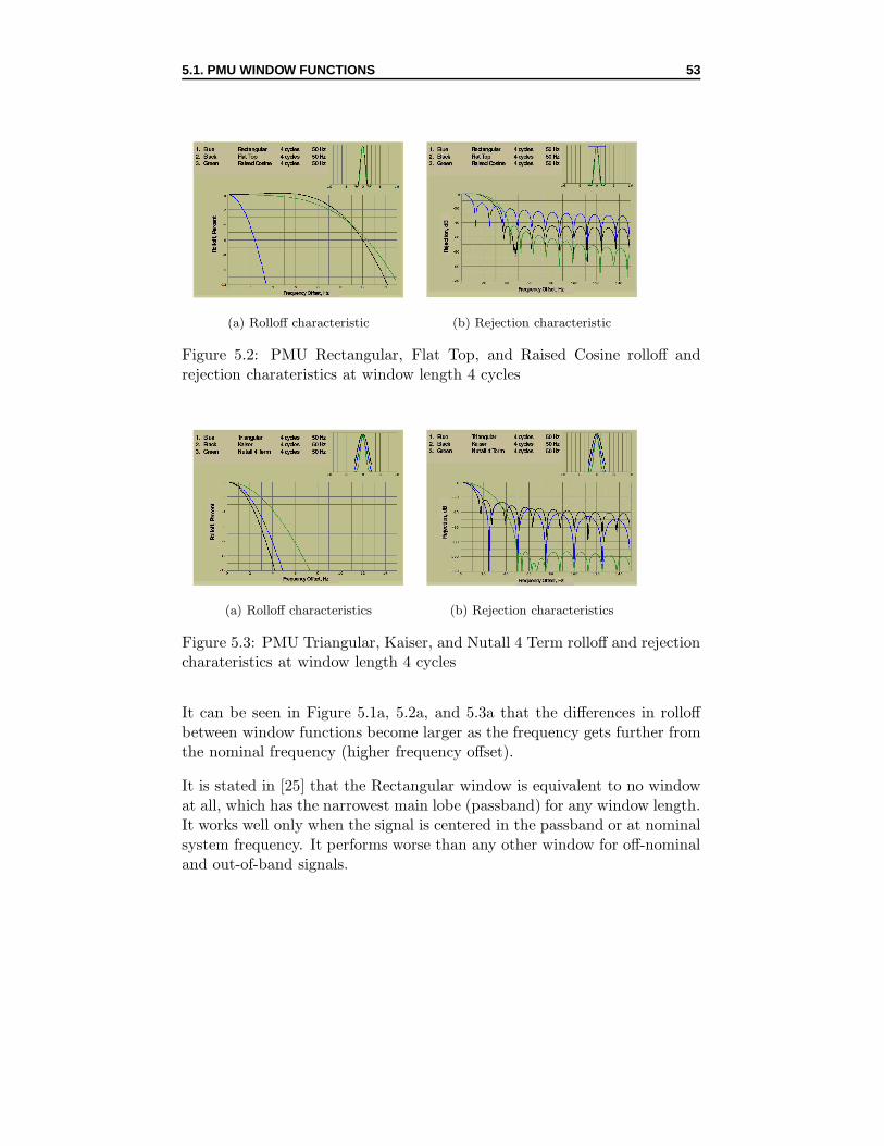
It can be seen in Figure 5.1a, 5.2a, and 5.3a that the differences in rolloffbetween window functions become larger as the frequency gets further fromthe nominal frequency (higher frequency offset).
It is stated in [25] that the Rectangular window is equivalent to no windowat all, which has the narrowest main lobe (passband) for any window length.It works well only when the signal is centered in the passband or at nominalsystem frequency. It performs worse than any other window for off-nominaland out-of-band signals.
5.1. PMU WINDOW FUNCTIONS 54
The Rectangular and Triangular windows, for most applications, are notrecommended. They are mostly applied for experiment purposes [25]. Theoften-used Hann and Blackman windows both have desirable characteristics,in which the magnitude of their rejection sidelobes decreases with increasingfrequency (Figure 5.1b). The Hamming window behaves similar to the Hannbut its rejection sidelobes do not decrease as quickly as the Hann (Figure5.1b). The Nutall 4 Term window is similar to the Hann and Blackman,with even better rejection characteristics (more than 90 dB) (Figure 5.3b).The Hann and Hamming (2-term), Blackman (3-term) and Nutall (4-term)all belong to the Blackman-Harris window family [25].
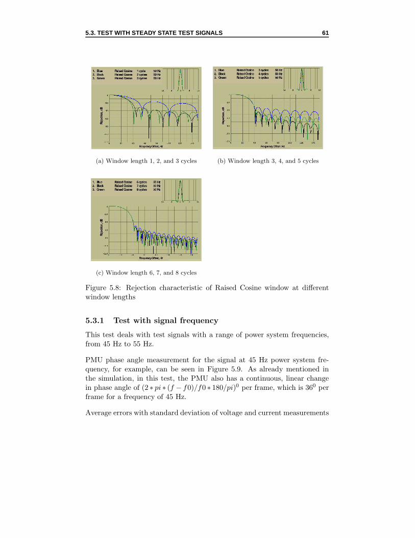
The Kaiser also has similar performance as the Blackman-Harris family (Fig-ure 5.3b). The Flat Top window has broader passband than other win-dows but its rejection is not as good as that of the other windows (Figure5.2). However, it is acceptable under many conditions and still much betterthan the Rectangular window [25]. The Raised Cosine window provides thebroadest flat passband with the rejection comparable to the Hann window(Figure 5.2).
5.1.2 Test on Window functions
This test is done on 9 estimator algorithms (windows) at 3 window lengths,i.e. 1, 2 and 4 cycles. The test signal used in this test is the steady state testsignal at nominal magnitude, nominal frequency and nominal phase angle.The resultant PMU errors are then plotted as a function of window lengthfor all windows.
Figure 5.4 and 5.5 represent PMU errors with window functions for PMUvoltage phase A and current phase A measurements.
FE are more than 10 times better than the standards for all windows atwindow length 1, 2, and 4 cycles. This error is lower for window length 2cycles and lowest for window length 4 cycles.
ROCOF error is quite high at window length 1 cycle. It even exceeds thestandard of 0.01 Hz/s (Flat Top). At window length 2 cycles, many win-dows (Hann, Hamming, Triangular, Blackman, Kaiser, Raised Cosine) haveROCOF error more than 10 times better than the standard. At windowlength 4 cycles, ROCOF errors of all windows are almost zero. For voltagemeasurement, TVE is quite high at window length 1 cycle (the smallest er-ror is 0.52 % and the highest is 1.8 %). At window length 2 cycles, TVE for
Figure 5.5: PMU errors as a function of window length for current test signal
5.2. TEST ON RAISED COSINE ESTIMATOR ALGORITHM 57
Flat Top, Kaiser and Nutall 4 Term and Blackman are much higher thanthe others. At window length 4 cycles, only Kaiser has TVE error up to 1% whereas the others result in quite small errors (less than 0.2 %) (Figure5.4c). In Figure 5.4e and 5.4d, it is found that Kaiser has higher PhaE thanthe others while Flat Top, Nutall 4 Term and Blackman have higher MagEthan the others.
The results of the current measurements are essentially equal to those of thevoltage measurements, which can be seen in Figure 5.5.
From these results we can make several conclusions. In the first place,window length 1 cycle is not suitable for accurate measurements. Windowlength 2 and 4 cycles, which provide more accurate measurements are, there-fore, selected for doing PMU tests. In the second place, an estimator needsto be chosen among the five best routines, i.e. Hann, Hamming, Rectangu-lar, Triangular and Raised Cosine for PMU testing.
In [28], the four-cycle Raised Cosine has been proved to be efficient in dy-namic phasor estimation for many reasons such as allowing to capture thebehavior of an oscillation. Accordingly, the Raised Cosine estimator algo-rithm has been suggested for coming PMU steady state and dynamic tests.
Finally, estimator algorithm Raised Cosine and window length 2 and 4 cycleswill be used in all coming PMU tests. To clearly illustrate for this choice,another test has been done on the Raised Cosine at window length from 1to 8 cycles.
5.2 Test on Raised Cosine estimator algorithm
Average errors with standard deviation for 3 phases are shown in Figure 5.6and 5.7 for voltage and current test signals.
Standard deviation σ shows the variation of measurements from the averagevalue. It is calculated using the following fomular:
σ =
√√√√ 1
(N − 1)
N∑
k=1
(Xi −X)2 [29] (5.1)
Where: N is the number of elements in the sample, X = 1
N
N∑k=1
Xi is the
average value.
5.3. TEST WITH STEADY STATE TEST SIGNALS 58
In PMU steady state tests, since each error is averaged over 49 frames andeach frame is the average of 7 measurements, the standard deviation calcu-lated for each error becomes:
σ′=
σ√49 ∗ 7
(5.2)
It can be seen in Figure 5.6 and 5.7 that the PMU has better measure-ment quality at window length 2, 4, and 6 cycles. This can also be seen inthe rejection characteristic of the Raised Cosine window at window lengthfrom 1 to 8 cycles (Figure 5.8). In Figure 5.8a, window length 1 cycle hasthe largest sidelobe amplitudes and poorly attenuated sidebands. Windowlength 2 cycles is slightly better than window length 3 cycles regarding side-lobe amplitudes and their attenuation. In figure 5.8b, window length 4 cycleshas more attenuated sidebands than window length 3 and 5 cycles. Windowlength 6, 7, and 8 cycles all have small sidelobe amplitudes and attenuatedsidebands (Figure 5.8c).
For dynamic tests, smaller window length may track more accurately signaldynamics. Window length 2 and 4 cycles rather than window length 6 cy-cles, therefore, have been selected for PMU tests.
The smallest TVE error is around 0.1 % at window length 4 cycles, which is10 times better than the standard. At window length 2 and 3 cycles, TVE ispartly from MagE and partly from PhaE. At window length 4, 5, 6, 7, and8 cycles, since MagE is essentially small, TVE is mostly caused by PhaE.The standard deviation has shown that there is not much variation in theerrors from their averages, which means that the measurements are stable.
Similar results can be found in 3 phases of the PMU, thus the analysis forother tests will be done for only 1 phase, i.e phase A.
5.3 Test with steady state test signals
All steady state test signals mentioned in 2.2.1 will be applied for testing thePMU at steady state conditions. The standard for steady state test signalsrequires a maximum FE of 5 mHz, RFE of 0.01 Hz/s and TVE of 1 %.
5.3. TEST WITH STEADY STATE TEST SIGNALS 59
1 2 3 4 5 6 7 8−5
−4
−3
−2
−1
0
1
2
3
4
5x 10
−4
Window length (cycles)
Fre
q er
ror
(Hz)
Phase APhase BPhase C
(a) Frequency error
1 2 3 4 5 6 7 8−0.01
−0.008
−0.006
−0.004
−0.002
0
0.002
0.004
0.006
0.008
0.01
Window length (cycles)
RO
CO
F e
rror
(H
z/s)
Phase APhase BPhase C
(b) ROCOF error
1 2 3 4 5 6 7 80
0.02
0.04
0.06
0.08
0.1
0.12
0.14
0.16
0.18
0.2
Window length (cycles)
TV
E e
rror
(%
)
Phase APhase BPhase C
(c) TVE error
1 2 3 4 5 6 7 8
−0.1
−0.05
0
0.05
0.1
0.15
Window length (cycles)
Mag
nitu
de e
rror
(%
)
Phase APhase BPhase C
(d) Magnitude error
1 2 3 4 5 6 7 8−0.1
−0.05
0
0.05
0.1
Window length (cycles)
Pha
se e
rror
(de
g)
Phase APhase BPhase C
(e) Phase error
Figure 5.6: PMU errors as a function of window length with Raised Cosinewindow for voltage test signal
5.3. TEST WITH STEADY STATE TEST SIGNALS 60
1 2 3 4 5 6 7 8−5
−4
−3
−2
−1
0
1
2
3
4
5x 10
−4
Window length (cycles)
Fre
q er
ror
(Hz)
Phase APhase BPhase C
(a) Frequency error
1 2 3 4 5 6 7 8−0.01
−0.008
−0.006
−0.004
−0.002
0
0.002
0.004
0.006
0.008
0.01
Window length (cycles)
RO
CO
F e
rror
(H
z/s)
Phase APhase BPhase C
(b) ROCOF error
1 2 3 4 5 6 7 80
0.02
0.04
0.06
0.08
0.1
0.12
0.14
0.16
0.18
0.2
Window length (cycles)
TV
E e
rror
(%
)
Phase APhase BPhase C
(c) TVE error
1 2 3 4 5 6 7 8
−0.1
−0.05
0
0.05
0.1
0.15
Window length (cycles)
Mag
nitu
de e
rror
(%
)
Phase APhase BPhase C
(d) Magnitude error
1 2 3 4 5 6 7 8−0.1
−0.05
0
0.05
0.1
Window length (cycles)
Pha
se e
rror
(de
g)
Phase APhase BPhase C
(e) Phase error
Figure 5.7: PMU errors as a function of window length with Raised Cosinewindow for current test signal
5.3. TEST WITH STEADY STATE TEST SIGNALS 61
(a) Window length 1, 2, and 3 cycles (b) Window length 3, 4, and 5 cycles
(c) Window length 6, 7, and 8 cycles
Figure 5.8: Rejection characteristic of Raised Cosine window at differentwindow lengths
5.3.1 Test with signal frequency
This test deals with test signals with a range of power system frequencies,from 45 Hz to 55 Hz.
PMU phase angle measurement for the signal at 45 Hz power system fre-quency, for example, can be seen in Figure 5.9. As already mentioned inthe simulation, in this test, the PMU also has a continuous, linear changein phase angle of (2 ∗ pi ∗ (f − f0)/f0 ∗ 180/pi)0 per frame, which is 360 perframe for a frequency of 45 Hz.
Average errors with standard deviation of voltage and current measurements
5.3. TEST WITH STEADY STATE TEST SIGNALS 62
0 10 20 30 40 500
50
100
150
200
250
300
350
Frame
PMU
phas
e an
gle
(deg
)
Figure 5.9: PMU phase angle at 45Hz
for Raised Cosine estimator algorithm at window length 2 and 4 cycles areshown in Figure 5.10 and 5.11.
The PMU is found to have very accurate measurement at both nominal andoff-nominal frequency for voltage and current signals. Most FE, RFE andTVE are 10 times better than the standard. Besides, at off-nominal fre-quencies, the dispersion of frequency and ROCOF measurements is higherthan that at nominal frequency. TVE error is also higher at off-nominalfrequencies. At 47 Hz, 48 Hz, 52 Hz, and 54 Hz, TVE errors are surpris-ingly high (even exceed the limit of 1 %), which are due to high MagE. At45 Hz and 55 Hz, MagE of window length 4 cyles are slightly higher thanthose at other frequencies, which also causes a little higher TVE. At the restfrequencies, PhaE contributes most to TVE error. Furthermore, it can beseen that window length 4 cycles most of the times results in more accuratemeasurement than window length 2 cycles.
5.3.2 Test with signal magnitude
In this test, the PMU will measure a steady state voltage signal with a mag-nitude range of 10 %, 80 %, 90 %, 100%, 110% and 120% of the nominal;and a current signal with a magnitude range of 10 %, 50 %, 75 %, 100 % and
5.3. TEST WITH STEADY STATE TEST SIGNALS 63
44 46 48 50 52 54 56−4
−2
0
2
4
6x 10
−4
Frequency (Hz)
Fre
quen
cy e
rror
(H
z)
Window length 2Window length 4
(a) Va Frequency error
44 46 48 50 52 54 56−0.015
−0.01
−0.005
0
0.005
0.01
0.015
0.02
Frequency (Hz)
RO
CO
F e
rror
(H
z/s)
Window length 2Window length 4
(b) Va ROCOF error
44 46 48 50 52 54 560
0.5
1
1.5
2
Frequency (Hz)
TV
E e
rror
(%
)
Window length 2Window length 4
(c) Va TVE error
44 46 48 50 52 54 56−2
−1.5
−1
−0.5
0
0.5
Frequency (Hz)
Mag
nitu
de e
rror
(%
)
Window length 2Window length 4
(d) Va Magnitude error
44 46 48 50 52 54 56−0.065
−0.06
−0.055
−0.05
−0.045
−0.04
−0.035
−0.03
−0.025
Frequency (Hz)
Pha
se e
rror
(de
g)
Window length 2Window length 4
(e) Va Phase error
Figure 5.10: PMU errors as a function of power system frequency for voltagetest signal
5.3. TEST WITH STEADY STATE TEST SIGNALS 64
44 46 48 50 52 54 56−4
−2
0
2
4
6x 10
−4
Frequency (Hz)
Fre
quen
cy e
rror
(H
z)
Window length 2Window length 4
(a) Ia Frequency error
44 46 48 50 52 54 56−0.015
−0.01
−0.005
0
0.005
0.01
0.015
0.02
Frequency (Hz)
RO
CO
F e
rror
(H
z/s)
Window length 2Window length 4
(b) Ia ROCOF error
44 46 48 50 52 54 560
0.5
1
1.5
2
Frequency (Hz)
TV
E e
rror
(%
)
Window length 2Window length 4
(c) Ia TVE error
44 46 48 50 52 54 56−2
−1.5
−1
−0.5
0
0.5
Frequency (Hz)
Mag
nitu
de e
rror
(%
)
Window length 2Window length 4
(d) Ia Magnitude error
44 46 48 50 52 54 56−0.075
−0.07
−0.065
−0.06
−0.055
−0.05
−0.045
−0.04
−0.035
Frequency (Hz)
Pha
se e
rror
(de
g)
Window length 2Window length 4
(e) Ia Phase error
Figure 5.11: PMU errors as a function of power system frequency for currenttest signal
5.3. TEST WITH STEADY STATE TEST SIGNALS 65
150 % of the nominal. The test is performed by measuring a combination ofvoltage and current signals with different magnitudes in each measurement,i.e. one measurement is performed with voltage signal of 10 % of its nominalvalue and current signal of 10 % of its nominal value, another measurementis done with voltage signal of 80 % of its nominal value and current signal of50 % of its nominal value, etc. From this measurement, the current signalat nominal magnitude is measured twice, which means that there are twovalues of each error for current measurement at nominal magnitude.
0 50 100 150 200−2
−1
0
1
2
3
4x 10
−4
Percentage of nominal magnitude (%)
Fre
quen
cy e
rror
(H
z)
Va win 2Ia win2Va win4Ia win4
(a) Frequency error
0 50 100 150 200−0.03
−0.02
−0.01
0
0.01
0.02
Percentage of nominal magnitude (%)
RO
CO
F e
rror
(H
z/s)
Va win 2Ia win2Va win4Ia win4
(b) ROCOF error
0 50 100 150 2000
0.2
0.4
0.6
0.8
1
Percentage of nominal magnitude (%)
TV
E e
rror
(%
)
Va win 2Ia win2Va win4Ia win4
(c) TVE error
0 50 100 150 200−1
−0.8
−0.6
−0.4
−0.2
0
0.2
0.4
Percentage of nominal magnitude (%)
Mag
nitu
de e
rror
(%
)
Va win 2Ia win2Va win4Ia win4
(d) Magnitude error
Figure 5.12: PMU errors as a function of signal magnitudes
Figure 5.12 shows the average errors with standard deviation for both cur-rent and voltage measurements at window length 2 and 4 cycles with RaisedCosine estimator algorithm. It can be seen that FE, RFE, and TVE arehighest at 10 % of the nominal magnitude for both current and voltage
5.3. TEST WITH STEADY STATE TEST SIGNALS 66
measurements while around nominal magnitudes, they conform well to therequirements in the standard. The standard deviation of the measurementsis also much higher at 10 % of the nominal magnitude than at other mag-nitudes.
The PMU has slightly smaller TVE errors for voltage measurements thanfor current measurements. Again, window length 4 cycles can be seen toprovide better measurement quality than window length 2 cycles. The low-est TVE error at window length 4 cycles for voltage measurement is 0.0635% and for current measurement is 0.0880 % (at their nominal magnitudes).At 10 % of the nominal magnitude, TVE errors are dominated by MagE. Atthe other magnitudes, with voltage measurement, TVE error is caused byPhaE at window length 4 cycles while at window length 2 cycles, it is fromboth MagE and PhaE. With current measurement, TVE is similar for bothwindow length 2 and 4 cycles, which is mostly caused by PhaE (except at75 % of the nominal magnitude).
5.3.3 Test with signal phase angle
The steady state test signal used in this test has a range of phase angle,i.e. 00, ±450, ±900, ±1350 and ±1800. This test is also performed bymeasuring a combination of voltage and current signals with different phaseangles in each measurement, i.e. one measurement is performed with voltageand current signals of 00, another measurement is done with voltage andcurrent signals of −450, other measurement is performed with voltage signalof −450 and current signal of +450, etc. Totally, current signals of −450,−900, −1350 and −1800, and voltage signals of 450, 900, 1350 and 1800 aremeasured twice. As a result, there are two values of each error at thesephase angles of voltage and current signals.
According to the specifications of the instrument [24], the PMU has a phaseerror of less than 0.030 + (time base error*3600*freq). Time base error isthe time uncertainty in the measurement setup, which is 3 µs. As a result,the maximum theoretical phase error of the PMU is 0.030+(3µs*360*50) or0.0840. Ideally, if the time base error is 0 µs, the phase error of the PMUbecomes 0.030.
It can be seen in Figure 5.13e that for window length 4 cycles, at 00, thePhaE for voltage is -0.0370 and for current is -0.0430. At other phase angles,the PMU measures with a PhaE of around -0.040 and -0.050 for voltage andaround -0.0450 and -0.060 for current. Window length 2 cycles has lower
5.3. TEST WITH STEADY STATE TEST SIGNALS 67
−200 −100 0 100 200−5
0
5
10
15x 10
−5
Phase (degree)
Fre
quen
cy e
rror
(H
z)
Va win 2
Ia win2
Va win4
Ia win4
(a) Frequency error
−200 −100 0 100 200−2
−1.5
−1
−0.5
0
0.5
1
1.5
2x 10
−3
Phase (degree)
RO
CO
F e
rror
(H
z/s)
Va win 2
Ia win2
Va win4
Ia win4
(b) ROCOF error
−200 −100 0 100 2000
0.05
0.1
0.15
0.2
0.25
0.3
0.35
Phase (degree)
TV
E e
rror
(%
)
Va win 2
Ia win2
Va win4
Ia win4
(c) TVE error
−200 −100 0 100 200−0.1
−0.05
0
0.05
0.1
0.15
0.2
0.25
Phase (degree)
Mag
nitu
de e
rror
(%
)
Va win 2
Ia win2
Va win4
Ia win4
(d) Magnitude error
−200 −100 0 100 200−0.12
−0.1
−0.08
−0.06
−0.04
−0.02
0
Phase (degree)
Pha
se e
rror
(de
gree
)
Va win 2
Ia win2
Va win4
Ia win4
(e) Phase error
Figure 5.13: PMU errors as a function of signal phase angles
5.3. TEST WITH STEADY STATE TEST SIGNALS 68
PhaE at positive phase angles and higher PhaE at negative phase anglesthan window length 4 cycles. In Figure 5.13d, voltage MagE of windowlength 4 cycles are quite small at all phase angles (from 0.003 % to 0.012 %)while current MagE is higher with more variation at different phase angles(from 0 to 0.075 %). In Figure 5.13c, with window length 4 cycles, TVEerror for voltage measurement is less than 0.1 % at all phase angles. Forcurrent measurement, this error is higher at negative phase angles than thatat other phase angles. Current measurement at window length 2 cyclescause lightly higher MagE at phase angles ±1800, ±1350, and 900, whichpartly results in higher TVE, along with PhaE. FE and RFE are small atany phase angles (Figure 5.13a and 5.13b).
5.3.4 Test with harmonic distortion
The test is done on signals with the 3rd harmonic, 5rd harmonic, and 3rd
and 5rd harmonics to estimate the PMU measurement quality with differentharmonic contents.
Figure 5.14 shows PMU average errors with standard deviation for the threeharmonic signals.
It can be found in Figure 5.14a that FE is highest for signal with the 3rd
and 5rd harmonics and smallest for signal with only the 3rd harmonic. Thehighest FE is 1.6 ∗ 10−4 Hz while the maximum FE required is 5 ∗ 10−3 Hz.Generally, the accuracy in frequency measurement of the PMU increaseswith higher harmonic contents and higher harmonic orders. More variationsin FE errors from their average values can also be observed for signal withthe 5rd harmonic and signal with the 3rd and 5rd harmonics.
Similar results for TVE error can be seen in Figure 5.14c with higher TVEerrors for higher harmonic contents and harmonic orders. TVE error forvoltage measurement is lower than that for current measurement at win-dow length 4 cycles. In addition, window length 4 cycles provides morestable magnitude measurements than window length 2 cycles, i.e. MagEsare almost the same for measurements with different harmonic contents. Atwindow length 4 cycles, TVE is mostly from PhaE for voltage measurement,and it is from both MagE and PhaE for current measurement.
The test result has also shown a similarity with the simulation in that FEand TVE errors are highest for signals with the 3rd and 5th harmonics.However, in the simulation, FE and TVE errors of signal containing the 3rd
5.3. TEST WITH STEADY STATE TEST SIGNALS 69
3rd 5th 3rd and 5th−1
0
1
2
3
4
5
6
7x 10
−4
Harmonic
Fre
quen
cy e
rror
(H
z)
Va win2Ia win2Va win4Ia win4
(a) Frequency error
3rd 5th 3rd and 5th−0.01
−0.005
0
0.005
0.01
0.015
0.02
0.025
0.03
Harmonic
RO
CO
F e
rror
(H
z/s)
Va win2Ia win2Va win4Ia win4
(b) ROCOF error
3rd 5th 3rd and 5th0.04
0.06
0.08
0.1
0.12
0.14
0.16
0.18
0.2
Harmonic
TV
E e
rror
(%
)
Va win2Ia win2Va win4Ia win4
(c) TVE error
3rd 5th 3rd and 5th−0.2
−0.15
−0.1
−0.05
0
0.05
Harmonic
Mag
nitu
de e
rror
(%
)
Va win2Ia win2Va win4Ia win4
(d) Magnitude error
3rd 5th 3rd and 5th−0.08
−0.07
−0.06
−0.05
−0.04
−0.03
Harmonic
Pha
se e
rror
(de
g)
Va win2Ia win2Va win4Ia win4
(e) Phase error
Figure 5.14: PMU errors as a function of signal harmonic distortion
5.4. TEST WITH DYNAMIC TEST SIGNALS 70
harmonic are higher than those of signal containing the 5th harmonic. Inthe test, it is vice versa.
5.4 Test with dynamic test signals
The dynamic behavior of the PMU can be evaluated through dynamic testswith all the dynamic test signals described in 2.2.2. These signals consist ofmodulated test signals, frequency ramp test signals, and input step changesignals. Each PMU error, FE, RFE or TVE, has 49 values in 49 frames.These errors are the average errors of 7 measurements in each frame. Inthe test with modulated signals and frequency ramp signals, changes insignal phase angle and signal frequency has led to wrong operation of theDiscrete Fourier Matlab Simulink block, which results in wrong magnitudesand phase angles. The reference data, there fore, could not be analyzed usingthis method. Instead, the phase angles and magnitudes of the reference dataare calculated on the basis of the theoretical test signals mentioned in part2.2.2 (applying formula (2.5) and (2.8)). The reference phase angles are thenthe theoretical phase angles plus the phase errors of the above measurementof steady state signal at nominal magnitude, nominal frequency, and zerophase angle (part 5.5.3).
5.4.1 Test with modulated test signals
The test is done with combined and phase modulated test signals, voltageand current, at modulation frequency 1 Hz, 2 Hz, 5 Hz and 10 Hz. PMUerrors are then plotted as a function of frame. In this test, the PMU isexpected to meet the standard of 0.3 Hz for FE, 30 Hz/s for RFE and 3 %for TVE up to modulation frequency 5 Hz or Fs/5 Hz (10 Hz).
Figure 5.15, 5.16, and 5.17 respectively show PMU errors for combined andphase modulated voltage signals at modulation frequency 1 Hz, 2 Hz, and 5Hz.
At 1 Hz modulation frequency (Figure 5.15), FE, TVE, MagE and PhaE alsofollow the modulation of the signals as already seen in the simulation. Eacherror makes one sinusoidal cycle over 50 time frames, which is also the mod-ulation cycle of the signals, but the test results are certainly not as smoothas the simulation results. FE and RFE are the same for phase and combinedmodulated signals at both window length 2 and 4 cycles. The maximum FEis 0.1 Hz and the maximum RFE is 0.6 Hz/s, which are quite far below the
5.4. TEST WITH DYNAMIC TEST SIGNALS 71
standard. The effect of window lengths on PMU measurements can be seenmore obviously in TVE error (Figure 5.15c). It is found that window length2 cycles results in much higher TVE than window length 4 cycles. Withwindow length 4 cycles, the maximum TVE for phase modulated signal is0.18 % and for combined modulated signal is 0.145 %, which is more than10 times better than the standard of 3 %. A big difference between the twowindow lengths can also be observed in MagE (Figure 5.15d). Besides, itcan be seen that at window length 4 cycles, PMU measurement with phasemodulated signal has a sinusoidal PhaE and an almost constant MagE over49 time frames whereas measurement with combined modulated signal hasboth sinusoidal PhaE and sinusoidal MagE. As a result, at window length 4cycles, TVE is largely caused by PhaE for phase modulated signals and it isthe contribution of both MagE and PhaE for combined modulated signals.At window length 2 cycles, TVE is from both MagE and PhaE for bothtypes of modulated signals.
In the same manner, PMU errors at 2 Hz modulation frequency are illus-trated in Figure 5.16. The maximum FE is now 0.2 Hz and maximum RFEis 2.5 Hz/s. These errors are almost the same as those obtained in thesimulation mentioned in 3.2.1 (Figure 3.6 and 3.7). At window length 4cycles, the maximum TVE for combined modulated signal is 0.22 % and forphase modulated signal is only 0.203 % (Figure 5.16c). PhaE for combinedmodulated signal reaches a maximum of 0.120 (or 0.21%) while for phasemodulated signal, it is 0.1150 (or 0.202 %) (Figure 5.16e). The PMU couldtrack accurately the magnitude of the modulated signals with a maximumerror of only 0.032 % for combined modulated signal and -0.0165 % for phasemodulated signal (Figure 5.16d).
At 5 Hz modulation frequency (Figure 5.17), FE has reached 0.5 Hz andRFE has reached 15 Hz/s. With window length 4 cycles, the maximumTVE for combined modulated signal is 0.37 % and for phase modulatedsignal is only 0.33 %. In this case, TVE and RFE still meet the standard.FE, however, has exceeded its limit of 0.3 Hz. In other words, up to 5 Hzmodulation frequency, the PMU could not follow the frequency change butit could still follow the changes in signal magnitude and phase angles.
In Figure 5.18, PMU errors for combined and phase modulated current sig-nals at modulation frequency 2 Hz are shown. It can be seen that the PMUhas similar behavior for current measurement as for voltage measurement.However, for current, the errors do not follow the modulation as smoothly
Figure 5.18: PMU errors for 2 Hz modulated current test signal
5.4. TEST WITH DYNAMIC TEST SIGNALS 76
5.4.2 Test with frequency ramp signals
In this test, the measurement performance of the PMU during system fre-quency change is tested with frequency ramp voltage and current signalsat ramp rates ±1 Hz/s from the nominal frequency. PMU errors are thenplotted over 49 time frames. The PMU should conform to the standard of1 % for TVE, 0.005 Hz for FE and 0.1 Hz/s for RFE.
For each 1 second test signal, 7 measurements are also done in 7 sec. Con-sequently, there are frequency jumps in the several first frames of each mea-surement, which causes huge PMU errors. Hence, in the plots of PMUerrors, the three first frames are ignored.
In Figure 5.19, PMU errors for voltage and current signals at ramp rate±1 Hz/s have been shown. With the ramp rate +1 Hz/s, the frequencyincreases gradually from 50 Hz to 51 Hz in 1 sec, and with the ramp rate -1Hz/s, the frequency decreases from 50 Hz to 49 Hz in 1 sec. It can be seenthat during the ramps, FE is approximately 0.01 Hz, which has exceeded thestandard of 0.005 Hz. The maximum RFE is less than 0.1 Hz/s. At ramprate +1 Hz/s, window length 4 cycles causes rather high PhaE (maximum of0.540 for current and 0.740 for voltage). This leads to the maximum TVE of0.96 % for current and 1.3 % for voltage. Window length 2 cycles, however,results in TVE of less than 0.4 % for both positive and negative ramps.
It can be found in Figure 5.19d that there are some steps in MagE with astrange behavior in current measurement at window length 2 and 4 cyclesand voltage measurement at window length 2 cycles. MagEs are quite highat the beginning of the ramp (close to the nominal frequency) and they de-crease gradually until the end of the ramp. A reason for this is the frequencydiscontinuity introduced at the beginning of each measurement.
As stated in the standard, this frequency ramp test should be performedwithout any discontinuity of frequency in the range of ±5Hz, which meansthe test should be performed on a 10 s signal with 5 s ramp up (ramp rate+1 Hz/s) followed by 5 s ramp down (ramp rate -1 Hz/s). In our test, how-ever, since the test signal does not follow the standard, the resultant PMUerrors shown above are not relevant. Accordingly, conclusions concerningthe PMU behavior for frequency ramp signal can not be made.
5.4. TEST WITH DYNAMIC TEST SIGNALS 77
49 49.5 50 50.5 51−0.015
−0.01
−0.005
0
0.005
0.01
0.015
Frequency ( Hz )
Fre
quen
cy e
rror
( H
z )
Ia win2Ia win4Va win2Va win4
(a) Frequency error
49 49.5 50 50.5 51−0.2
−0.15
−0.1
−0.05
0
0.05
0.1
0.15
0.2
Frequency ( Hz )
RO
CO
F e
rror
( H
z/s
)
Ia win2Ia win4Va win2Va win4
(b) ROCOF error
49 49.5 50 50.5 510
0.2
0.4
0.6
0.8
1
1.2
1.4
Frequency ( Hz )
TV
E e
rror
( %
)
Ia win2Ia win4Va win2Va win4
(c) TVE error
49 49.5 50 50.5 51−0.3
−0.2
−0.1
0
0.1
0.2
Frequency ( Hz )
Mag
nitu
de e
rror
(%
)
Ia win2Ia win4Va win2Va win4
(d) Magnitude error
49 49.5 50 50.5 51−0.8
−0.6
−0.4
−0.2
0
0.2
Frequency ( Hz )
Pha
se e
rror
( d
eg )
Ia win2Ia win4Va win2Va win4
(e) Phase error
Figure 5.19: PMU errors for ±1 Hz frequency ramp test signal
5.4. TEST WITH DYNAMIC TEST SIGNALS 78
5.4.3 Test with step change signals
In this test, the PMU performance during step changes in magnitude andphase will be estimated with 1 sec magnitude and phase step signals. Themagnitude step signal has a positive step of +10 % in magnitude at 0.2sand a negative step of -10 % at 0.7s, likewise the phase step has a positivestep of 100 at 0.2s and a negative step of −100 at 0.7s. The response time,delay time, and overshoot in PMU measurement will also be determined inthis test. The PMU should meet the standard of 1 % for TVE, 0.005 Hz forFE and 0.01 Hz/s for RFE during steady state periods. During transientperiods, it should comply with the limit of 1/(4*Fs) or 5 ms for delay time,10 % of step magnitude for overshoot, 0.199 s for TVE response time, 0.130s for FE response time, and 0.134 s for RFE response time.
Below is only the analysis for voltage measurement. Similar analysis hasbeen done for current measurement but it is not presented due to timelimit.
It can be seen in Figure 5.22 that PMU measurement with the phase stepsignal is 4.550 or 7.98 % higher in PhaE and 2.7 % (positive step) or 5 %(negative step) lower in MagE than the magnitude step signal during stepinstants. The resultant FE, RFE, and TVE for the phase step signal are,therefore, higher than those for the magnitude step signal. Besides, it can beseen clearly that MagE is much higher than PhaE for magnitude step signalat the transitions, and hence TVE error for magnitude step signal mea-surement is mainly due to MagE. Contrarily, for phase step signal, PhaE ishigher than MagE, thus TVE error is mostly from PhaE.
Response delay and overshoot for magnitude step signal are illustrated inFigure 5.20a. It can be seen more clearly in Figure 5.20b that at positivestep, the response delay is (0.2011-0.2) sec or 0.0011 sec (1.1 ms). Thisdelay conforms well to the standard (5 ms). The magnitude overshoot is(63.7440-63.5150) V or 0.229 V while the maximum allowed overshoot is 10% of (63.5150-57.7440) V or 0.577 V according to the standard. Measure-ment with window length 2 and window length 4 leads to the same responsedelay. However, measurement with window length 2 results in no magni-tude overshoot. Similarly, at negative step, response delay, response timeand overshoot are also below their limits.
As can be seen in Figure 5.21a and 5.21b, the response delay for phase stepsignal is (0.2001-0.2) sec or 0.1 ms and the overshoot is (190.2060−189.7310)0
5.4. TEST WITH DYNAMIC TEST SIGNALS 79
or 0.47500. The maximum overshoot required in the standard for the phasestep signal measurement is 10 % of 100 or 10, thus the PMU has satisfiedthe requirement for response delay and overshoot.
Response times for FE, RFE, and TVE are presented in Figure 5.21c, 5.21d,and 5.21e. TVE response times are the same for both magnitude and phasestep signal, at both window length 2 and 4 cycles, and they are approx-imately the time difference between the 10th and the 12th frame (Figure5.21e), i.e. 0.04 s compared to the requirement of 0.199 s in the standard.From Figure 5.21c, FE response time for phase step signal at window length4 cycles is approximately the time difference between the 9th and the 14th
frame, i.e. 5*0.02 s or 0.1 s. For phase step signal at window length 2 cycles,and magnitude step signal at window length 2 and 4 cycles, FE responsetimes are approximately the time difference between the 10th and the 13th
frame, i.e. 3*0.02 s or 0.06 s. The standard requires a maximum FE responsetime of 0.130 s, thus the PMU meets the requirement for FE response timeat all window lengths for both magnitude and phase step signals.
Similarly, RFE response times are shown in Figure 5.21d. For phase stepsignal, at window length 4 cycles, RFE response time is nearly the timedifference between the 9th and the 15th frame or 0.12 s. For phase stepsignal at window length 2 cycles as well as magnitude step signal at windowlength 2 and 4 cycles, RFE response time is more or less the time differencebetween the 10th and 14th frame or 0.08 s.
To sum up, the PMU could perform well with magnitude step signals of 10% and phase step signals of 100 regarding overshoots, response delay, andresponse times.
5.5. TEST WITH FAULT SIGNALS 80
0 0.2 0.4 0.6 0.8 157
58
59
60
61
62
63
64
X: 0.54Y: 63.52
Time (s)
Va
mag
nitu
de (
V )
win2win4
Response delayOvershoot
50% of step value
(a) Response delay and overshoot
0.2 0.2005 0.201
60.734
60.736
60.738
60.74
60.742
60.744
60.746
X: 0.2011Y: 60.74
Time (s)
Va
mag
nitu
de (
V )
win2win4
Response delay50% ofstep value
(b) Zoom in response delay and overshoot
Figure 5.20: PMU response delay and overshoot for magnitude step voltagesignal
5.5 Test with fault signals
In this test, the PMU behavior under fault conditions is estimated by thesingle-phase fault on phase A of a 110 kV bus. The fault current Ia isincreased from its normal value of 420 A to the fault value of 1391 A duringthe fault occurrence. The currents of phase B and C and the voltages of 3phases only suffer from small steps during the fault. For this reason, onlyanalysis for the fault current Ia is necessary.
From Figure 5.24a, 5.24b and 5.24c, the response delay for window length 2cycles is (0.2002-0.2) s or 0.2ms, for window length 4 cycles is (0.2-0.1798)s or 20.2 ms. The overshoot for window length 2 cycles is (3.2430-3.1320)A or 0.1110 A, for window length 4 cycles is (3.7250-3.4780) A or 0.2470A. The standard requires this overshoot to be 10 % of (3.4760-1.0505) A or0.243 A.
It can be seen in Figure 5.24d that at the fault occurrence, TVE responsetime for window length 2 cycles is approximately the time difference betweenthe 10th and the 13th frame or 0.06s whereas for window length 4, it isapproximately the time difference between the 8th frame and the 13th frame,i.e. 0.1 s. Similarly, FE response time for window length 2 and 4 cycles isaround 0.04 s (Figure 5.24e). RFE response time for window length 2 cyclesis 0.08 s, and for window length 4 cycles is 0.1 s (Figure 5.24f). At theinstant that the current recovers to its initial value from the fault value,
5.5. TEST WITH FAULT SIGNALS 81
0 0.2 0.4 0.6 0.8 1178
180
182
184
186
188
190
192
X: 0.48Y: 189.7
Time (s)
Va
phas
e an
gle
( de
g )
win2win4Overshoot
Response delay
50% of step value
(a) Response delay and overshoot for phasestep signal
Figure 5.22: PMU errors for step voltage test signal
5.5. TEST WITH FAULT SIGNALS 83
these parameters are determined in the same way and they also meet thestandard.
It can also be seen in Figure 5.23d and 5.23e for MagE and PhaE thatthe PMU perform more accurate magnitude and phase measurements withwindow length 4 cycles than with window length 2 cycles.
In general, the PMU could conform to the standard for overshoot, delaytime, TVE response time, FE response time, and RFE response time in suchfault condition as the above single-phase short circuit situation. Besides,window length 4 cycles, on the one hand, results in better magnitude andphase angle measurements than window length 2 cycles, on the other hand, itperforms worse than window length 2 cycles regarding overshoot, delay time,and response times. Therefore, depending on specific purposes, whethermeasurement accuracy or measurement response is more important, eitherwindow length 2 cycles or window length 4 cycles should be chosen.
5.5. TEST WITH FAULT SIGNALS 84
0 10 20 30 40 50−0.02
−0.01
0
0.01
0.02
0.03
Frame
Fre
quen
cy e
rror
(H
z)
window length 2window length 4
(a) Frequency error
0 10 20 30 40 50−1.5
−1
−0.5
0
0.5
1
1.5
Frame
RO
CO
F e
rror
(H
z/s)
window length 2window length 4
(b) ROCOF error
0 10 20 30 40 500
20
40
60
80
100
120
140
Frame
TV
E e
rror
(%
)
window length 2window length 4
(c) TVE error
0 10 20 30 40 50−50
0
50
100
150
Frame
Mag
nitu
de e
rror
(%
)
Window length 2Window length 4
(d) Magnitude error
0 10 20 30 40 50−40
−20
0
20
40
60
Frame
Pha
se e
rror
(de
gree
)
Window length 2Window length 4
(e) Phase error
Figure 5.23: PMU errors for fault signal
5.5. TEST WITH FAULT SIGNALS 85
0 0.2 0.4 0.6 0.8 10.5
1
1.5
2
2.5
3
3.5
4
Time (s)
Ia
PMU win2PMU win4Ref win 2Ref win4
Response delay win 4
Overshoot win 4
Overshoot win 2
50% of step value win 4
50% of step value win 2
Response delay win 2
(a) Response delay and overshoot
0.2 0.2001 0.2002 0.2003 0.2004
2.0378
2.038
2.0382
2.0384
2.0386
2.0388
2.039
2.0392
time (s)
Ia
win2win4
Response delay win2
50% of step value
(b) Zoom in response delay window length 2
0.1796 0.1797 0.1798 0.1799 0.18
2.2638
2.264
2.2642
2.2644
2.2646
2.2648
2.265
2.2652
time (s)
Ia
win2win4
Response delay win4
50% of step value
(c) Zoom in response delay window length 4
5 10 15 20 25 30 35 40 45 500
0.5
1
1.5
2
2.5
3
3.5
4
4.5
5
Frame
TV
E e
rror
(%
)
window length 2window length 4
Response timewin 4
Response time win 2 Response timewin 2
Response time win 4
(d) TVE response time
5 10 15 20 25 30 35 40 45 50−0.02
−0.015
−0.01
−0.005
0
0.005
0.01
0.015
0.02
Frame
Fre
q er
ror
(Hz)
window length 2window length 4
Response time win 4 Responsetime win 4
Response time win 2
Responsetime win 2
(e) FE response time
5 10 15 20 25 30 35 40 45 50−0.1
−0.05
0
0.05
0.1
Frame
RO
CO
F e
rror
(H
z/s)
window length 2window length 4
Response time win2
Response time win4
Responsetime win4
Responsetime win2
(f) RFE response time
Figure 5.24: PMU responses for fault signal
Chapter 6
Conclusions and
Recommendations
6.1 Conclusions
• PMU measurement quality can be validated by means of TVE, FEand RFE. TVE is an accuracy index for evaluating both magnitudeand phase angle measurement while FE and RFE provide evaluationon the accuracy of frequency measurement.
• Requirements for PMU dynamic performance have been introducedinto the new standard, i.e. the C37.118-2011 IEEE Standard. Theserequirements include the allowed maximum TVE, FE and RFE forsuch dynamic tests as modulated tests, frequency ramp tests, andmagnitude and phase angle step tests. Additional requirements forstep tests in overshoot, response delay and response times have alsobeen provided. Specific requirements for steady state and dynamictests are represented in Appendix A.
• Among 9 PMU estimator algorithms, Hann, Hamming, Triangular,Rectangular, and Raised Cosine provide much better magnitude andphase angle measurements than the others. The Raised Cosine algo-rithm has been selected for the PMU tests. Moreover, the PMU hasbeen found to track more accurately signal magnitude and phase an-gles at window length 2, 4, and 6 cycles. Smaller window length couldbetter follow the changes of signal magnitude and phase angles in dy-namic tests and hence, the tests have been done with window length2 and 4 cycles.
86
6.1. CONCLUSIONS 87
• From the steady state tests, it can be seen that the Model 1133A PowerSentinel PMU has enough accuracy and robust performance in bothnominal and off-nominal steady state conditions. For a steady statesignal at nominal condition, the PMU is found to have a maximumphase error of -0.05770 (0.101 %) at window length 2 cycles and -0.05050 (0.089 %) at window length 4 cycles for voltage measurement.For current measurement, the maximum phase error is -0.06530 (0.115%) at window length 2 cycles and -0.06240 (0.11 %) at window length4 cycles. This implies the maximum time base error of the PMU isaround 2 µs.
• For the modulated test, the PMU has been found to track changes insignal magnitude and phase angles better than changes in frequency.At 5 Hz modulation frequency, FE has exceeded its standard of 0.3Hz while TVE is still far below the limit of 3 %. Measurements withwindow length 4 cycles provide more accurate results with lower mag-nitude and phase error than measurements with window length 2 cy-cles.
• For the frequency ramp test, due to frequency discontinuity introducedduring the test, considerably high frequency error has been observed.The frequency error at ±1 Hz/s frequency ramp is 0.01 Hz, which hasalready exceeded the requirement of 0.005 Hz. Since the test signaldoes not conform to the standard, no conclusion can be made for thePMU with frequency ramp test signal.
• For the step tests, the PMU has shown a reasonably good performanceregarding overshoot, delay time, and response times for signals with±10 % step in magnitude or ±100 step in phase. Except for transientinstants, FE, RFE, and TVE are all below their limits.
• The PMU has also been found to have a good performance in responseto the single-phase short circuit current. The overshoot, delay time,and response times are within the standard. Measurement with win-dow length 4 cycles could track more accurately signal magnitude andphase angles, yet its responses, including overshoot, delay time andresponse times, are worse than measurement with window length 2cycles. Therefore, depending on measurement purpose, measurementaccuracy or measurement response, window length 2 or 4 cycles canbe chosen. In addition, TVE error during the fault is extremely high,which is approximately 140 %.
6.2. RECOMMENDATIONS FOR FUTURE WORK 88
6.2 Recommendations for future work
• The timing error of the measurement setup is now 2 µs, which causesa maximum phase error of approximately 0.0650 or 0.114 %. It wouldbe better if this timing error is improved to less than 2 µs, and hencethe PMU phase error will be reduced to less than 0.1 %.
• Since the amplifiers are parts of the measurement setup, they havecertain influence on the measurement accuracy, especially the phaseangle measurement. These amplifiers, therefore, should be calibratedto provide more accurate measurement of the reference signals.
• The Discrete Fourier Matlab Simulink block has shown wrong behav-ior regarding magnitude and phase angle analysis for dynamic signalswhich have frequency or phase angle changes, other alternatives forextracting the magnitude and phase angle of the fundamental compo-nent of these reference signals should be developed.
• As for harmonic distortion test, higher harmonic orders (up to 50th
harmonic) should be included into the test signal to see how the PMUperforms with different harmonics and to which harmonic order itcould still conform to the standard. Besides, the PMU should also betested with interharmonics or out-of-band interference. The require-ment for this has also been mentioned in the standard. Additionally,testing the PMU with different noise levels is also recommended to seehow noises affect the PMU measurement quality.
• The frequency ramp test should be done without any discontinuity insignal frequency. In other words, the test signal should be generatedwith its frequency increasing from 45 Hz, for instance, to 55 Hz within10 s. In this case, the PMU can be tested with ramp rates ±1 Hz/s ina frequency range of ±5 Hz at the same time without any frequencyjump.
• Before being supplied to PMU inputs, power system currents and volt-ages are transformed to appropriate levels by current transformer andvoltage transformers. The behavior of these instrument transformersmay have some influence on PMU measurement quality. Therefore, itis also necessary to study how and to what extent these devices affectPMU measurement accuracy.
Bibliography
[1] IEEE Draft Standard for Synchrophasor Measurements for Power Sys-tems, IEEE Std C37.118-2011, May 2011
[2] Overbye T.J., Weber J.D., The Smart Grid and PMUs: OperationalChallenges and Opportunities, Power and Energy Society General Meet-ing, 2010 IEEE, pp.1-5
[3] IEEE Draft Standard for Synchrophasor Measurements for Power Sys-tems, IEEE Std C37.118-2005, June 2005
[4] Phadke A.G., Synchronized Phasor Measurement: A HistoricalOverview, Transmission and Distribution Conference and Exhibition2002: Asia Pacific IEEE/PES, Vol. 1, pp. 476-479
[5] Baldwin T.L., Mili L., Boisen M.B Jr., Adapa R., Power System Ob-servability with Minimal Phasor Measurement Placement, IEEE Trans-actions on Power Systems, 1993, Vol. 8, pp. 707-715
[6] Joe-Air Jiang, Jun-Zhe Yang, Ying-Hong Lin, Chih-Wen Liu, Jih-ChenMa, An adaptive PMU based fault detection/location technique fortransmission lines. I. Theory and algorithms, IEEE Transactions onPower Delivery, 2000, Vol. 15, pp. 486-493
[7] Joe-Air Jiang, Ying-Hong Lin, Jun-Zhe Yang, Tong-Ming Too, Chih-Wen Liu, An adaptive PMU based fault detection/location technique fortransmission lines. II. PMU implementation and performance evaluation,IEEE Transactions on Power Delivery, 2000, Vol. 15, pp. 1136-1146
[8] Terzija V., Valverde G., Deyu Cai, Regulski P., Madani V., Fitch, J.,Skok S., Begovic M.M., Phadke A., Wide-Area Monitoring, Protection,and Control of Future Electric Power Networks, Proceedings of the IEEE,2011, Vol. 99, pp. 80-93
89
BIBLIOGRAPHY 90
[9] Sangwook Han and B. Lee, S. Kim, Y. Moon, Development of Volt-age stability Index using synchro-phasor based data, Transmission andDistribution Conference and Exposition: Asia and Pacific, pp.1 - 4, 2009
[10] Sandro Corsi and Glauco N. Taranto, A Real-Time Voltage InstabilityIdentification Algorithm Based on Local Phasor Measurements, IEEEtransactions on power systems, v. 23, No. 3, pp. 1271-1279. August 2008
[11] James A. Momoh, Yan Xia and Garfield Boswell, Voltage Stability En-hancement using Phasor Measurement Unit (PMU) Technology, PowerSymposium, NAPS ’08, 40th North American, pp. 1 - 6. 2008
[12] Ashutosh Tiwari and V. Ajjarapu, Event Identification and Contin-gency Assessment for Voltage Stability via PMU, Power Symposium,NAPS ’07, 39th North American, pp. 413 - 420. 2007
[13] Mingsong Liu, Boming Zhang, Liangzhong Yao, Min Han, Hongbin Sunand Wenchuan Wu, PMU Based Voltage Stability Analysis for Trans-mission Corridors, Electric Utility Deregulation and Restructuring andPower Technologies, Third International Conference, pp.1815 - 1820,2008
[14] Mevludin Glavic and Thierry Van Cutsem, Detecting with PMUs theonset of voltage instability caused by a large disturbance, Power andEnergy Society General Meeting - Conversion and Delivery of ElectricalEnergy in the 21st Century, IEEE, pp. 1 - 8. 2008
[15] Stenbakken, G., Nelson, T., Static Calibration and Dynamic Character-ization of PMUs at NIST, Power Engineering Society General Meeting,2007, IEEE, pp. 1-4
[16] Stenbakken, G., Ming Zhou, Dynamic Phasor Measurement Unit TestSystem, Power Engineering Society General Meeting, 2007, IEEE, pp.1-8
[17] Garcia-Valle, R., Guang-Ya Yang, Martin, K.E., Nielsen, A.H., , ster-gaard J., DTU PMU laboratory development - Testing and validation,Innovative Smart Grid Technologies Conference Europe (ISGT Europe),2010 IEEE PES, 2010, pp. 1-6
[18] Yang G.Y., Martin K.E., , stergaard J., Investigation of PMU Perfor-mance Under TVE criterion, 5th International Conference on CriticalInfrastructure (CRIS) 2010, pp. 1-7
BIBLIOGRAPHY 91
[19] Stenbakken G., Nelson T., Ming Zhou, Centeno V., Reference Valuesfor Dynamic Calibration of PMUs, Hawaii International Conference onSystem Sciences, Proceedings of the 41st Annual, January 2008, Page171
[20] Stenbakken G.N., Calculating combined amplitude and phase modu-lated power signal parameters, Power and Energy Society General Meet-ing, IEEE, 2011 , pp. 1-7
[21] Martin K.E. Hamai D.; Adamiak M.G.; Anderson S.; Begovic M.; Ben-mouyal G.; Brunello G.; Burger J.; Cai J.Y.; Dickerson B.; GharpureV.; Kennedy B.; Karlsson D.; Phadke A.G.; Salj J.; Skendzic V.; SperrJ.; Song Y.; Huntley C.; Kasztenny B.; Price E., Exploring the IEEEStandard C37.118-2005 Synchrophasors for Power Systems, IEEE Trans-actions on Power Delivery, Volumn 23, Issue 4, October 2008, pp. 1805-1811
[22] North American Synchrophasor Initiative (NASPI), Performance andStandards Task Team (PSTT), PMU System Testing and CalibrationGuide, December 2007
[23] NI PXI 4461 application manual, National Instruments.
[24] Abiter Systems, Model 1133a power sentinel operational manual.
[25] Abiter Systems, Model 1133A Phasor Measurement Specifications,2007.
[26] National Instruments, NI PXI4461 specifications.
[27] U. Pogliano, J.P. Braun, B. Volj, and R. Lapuh, Software platform forPMU algorithms testing, Proc. CPEM Conf., 2012, pp. 412-413, Wash-ington, USA, 2012.
[28] Jacques Warichet, Tevfik Sezi, Jean-Claude Maun, Considerationsabout synchrophasors measurement in dynamic system conditions, In-ternational Journal of Electrical Power and Energy Systems, Volume 31,Issue 9, October 2009, pp. 452-464
Influence Reference Minimum range of influence quantity overquantity condition which PMU shall be within given TVE limit
Performance Class P Performance Class MRange Max Range Max
TVE (%) TVE (%)Signal frequency Fnominal(f0) ±2.0 Hz 1 ±2.0 Hz for Fs<10 1
range - fdev ±Fs/5 Hz for 10≤Fs<25- (test applied nominal ±5.0 Hz for Fs≥25+ deviation: f0±fdev)The Signal Frequency range test above are to be performed over the given ranges and meetthe given requirement at 3 temperatures: T = nominal (∼23oC), T = 0oC, and T = 50oC.
Phase angle with Constant or ±π radians 1 ±π radians 1|fin - f0| <0.25 Hz slowly
varying angleHarmonic distortion <0.2% 1%, each 1 10%, each 1(single harmonic) (THD) harmonic up harmonic
to 50th up to 50th
Out of band <0.2% of None 10% of input signal 1.3interference as input signal magnitude for Fs≥10.described below magnitude No requirement for
Fs<10.Out of band interference testing:The passband at each reporting rate is defined as |f - f0 | ≤ Fs/2.An interfering signal outside the filter passband is a signal at frequency f where:|f - f0 | ≥ Fs/2For test the input test signal frequency fin is varied between f0 and ±10% ofthe Nyquist frequency of the reporting rate(that is: f0 - 0.1Fs/2 ≤ fin ≤ f0 + 0.1Fs/2)Fs = phasor reporting ratef0 = nominal system frequencyfin = fundamental frequency of the input test signal
Table A.2: Steady-state frequency and ROCOF measurement re-quirements
Influence Reference Error requirements for compliancequantity condition Class P Class MSignal Frequency = f0 Range: f0 ± 2.0 Hz Range:
frequency (fnominal) f0 ± 2.0 Hz for Fs≤10Phase angle ±Fs/5 Hz for 10≤Fs<25constant ± 5.0 Hz for Fs≥25
Max FE Max RFE Max FE Max RFE0.005 Hz 0.01Hz/s 0.005 Hz 0.01 Hz/s
Harmonic < 0.2% THD 1 % each harmonic up to 50th 10 % each harmonic up to 50th
distortion (same Max FE Max RFE Max FE Max RFEas Table 3) Fs > 20 0.005 Hz 0.01Hz/s 0.025 Hz 6 Hz/s
(single harmonic) Fs ≤ 20 0.005 Hz 0.01Hz/s 0.005 Hz 2 Hz/sOut-of-band <0.2% of input No requirements Interfering signal 10%interference signal magnitude of signal magnitude(same as Max FE Max RFETable 3) None None 0.01 Hz .1 Hz/s
94
Table A.3: Synchrophasor measurement bandwidth requirementsusing modulated test signals
Modulation Reference Minimum range of influence quantity over which PMULevel condition shall be within given TVE limit
Class P Class MRange Max TVE Range Max TVE
kx = 0.1, 100% rated signal Modulation 3% Modulation 3%ka = 0.1 magnitude, fnominal frequency 0.1 to frequency 0.1 toradian lesser of Fs/10 Hz lesser of Fs/5 Hzkx = 0, 100% rated signal or 2 Hz 3% or 5 Hz 3%ka = 0.1 magnitude, fnominalradian
Table A.4: Frequency and ROCOF performance requirements un-der modulation tests
Modulation level, Reference condition, Range Error requirements for compliance(Use the same modulation levels andranges under the reference conditions Class P Class M
specified in Table 5 Max FE Max RFE Max FE Max RFEFs > 20 0.06 Hz 3 Hz/s 0.3 Hz 30 Hz/sFs ≤ 20 0.01 Hz 0.2 Hz/s 0.06 Hz 2 Hz/s
Table A.5: Synchrophasor measurement requirements under fre-quency ramp tests
Test signal Reference Minimum range of influence quantity over which PMUcondition shall be within given TVE limit
Class P Class MRamp rate (Rf ) (positive Performance Ramp Range Max TVE
& negative ramp) ClassLinear 100% rated ± 1.0 Hz/Sec Class P ± 2 Hz 1 %
frequency signal magnitude,ramp & fnominal at
start or some Class M Lesser of 1 %point during ± (Fs/5) Hz
the test or ± 5 Hz
Table A.6: Frequency and ROCOF performance requirements un-der frequency ramp tests
Signal Reference Transition Error requirements for compliancespecification condition timeRamp tests- 100% rated signal ± 2/Fs for the Class P Class M
same as magnitude & 0 start & end Max FE Max RFE Max FE Max RFEspecified in radian base of ramp 0.01 Hz 0.1 Hz/s 0.005 Hz 0.1 Hz/s
Table 7 angle
95
Table A.7: Phasor performance requirements for input step change
Step change Reference Maximum response time, delay time, and overshootspecification condition Class P Class M
Response |Delay Max Response |Delay Maxtime (s) time| Overshoot time (s) time| Overshoot
/undershoot /undershootMagnitude All test 1.7/f0 1/(4xFs) 5% of step See 1/(4xFs) 10% of step= ±10% conditions magnitude Table magnitude
kx = ±0.1 nominal at 11ka = 0 start or end
of stepAngle ±10o, All test 1.7/f0 1/(4xFs) 5% of step See 1/(4xFs) 10% of step
Table A.8: Frequency and ROCOF performance requirements forinput step change
Signal Reference Maximum susceptibility response timespecification condition Class P Class M
Frequency ROCOF Frequency ROCOFResponse time Response time Response time Response time
Magnitude test Same as in 3.5/f0 4/f0 See Table A.9 See Table A.9as in Table A.7 Table A.7Phase test as in Same as in 3.5/f0 4/f0 See Table A.9 See Table A.9
Table A.7 Table A.7
Table A.9: Response time for M-class phasor, Frequency and RO-COF for input step change
Maximum response time in step change test for M-class, in secondsReporting rate (Fs) 10 12 15 20 25 30 50 60 100 120Phasor (TVE) 0.595 0.493 0.394 0.282 0.231 0.182 0.199 0.079 0.050 0.035Frequency (FE) 0.869 0.737 0.629 0.478 0.328 0.305 0.130 0.120 0.059 0.053ROCOF (RFE) 1.038 0.863 0.691 0.520 0.369 0.314 0.134 0.129 0.061 0.056
Appendix B
An example of PMU output
phasors saved in *.txt file
UTC Time,Freq. (Hz),Ch A V,Phase(deg),Ch A I,Phase(deg),Ch B V,Phase(deg),Ch B I,Phase(deg),Ch C V,Phase(deg),Ch C I,Phase(deg)