Page 1
Why are particle accelerators so inefficient?
Philippe Lebrun
CERN, Geneva, Switzerland
Workshop on Compact and Low-Consumption Magnet Design for Future Linear and Circular Colliders
CERN, 9-12 October 2014
Page 2
Why bother about efficiency? M. van der Hoeven, Energy efficiency report 2013, IEA
Ph. Lebrun Workshop on Magnet Design Nov 2014 2
Page 3
The largest energy resource M. van der Hoeven, Energy efficiency report 2013, IEA
Ph. Lebrun Workshop on Magnet Design Nov 2014 3
Page 4
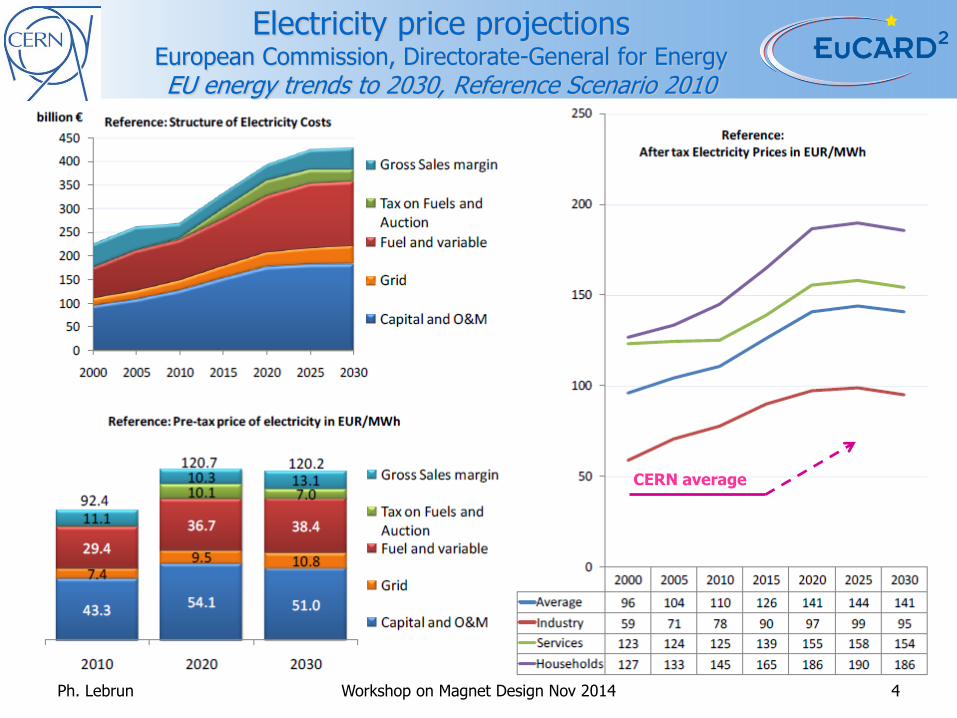
Electricity price projections European Commission, Directorate-General for Energy EU energy trends to 2030, Reference Scenario 2010
CERN average
Ph. Lebrun Workshop on Magnet Design Nov 2014 4
Page 5
Accelerator “black box” model
Ph. Lebrun Workshop on Magnet Design Nov 2014 5
Electricity 𝑷𝒈𝒓𝒊𝒅 Particle energy 𝑬
Particles on target 𝑵 Luminosity 𝓛
Heat 𝑸
Accelerator/Collider
Page 6
Accelerator “multi black box” model
Ph. Lebrun Workshop on Magnet Design Nov 2014 6
Heat
Beam power 𝑷𝒃𝒆𝒂𝒎 Stored energy 𝑾𝒃𝒆𝒂𝒎
“Intrinsic” losses
Accelerator systems
Infrastructure
Electricity 𝑷𝒈𝒓𝒊𝒅 Particle energy 𝑬
Particles on target 𝑵 Luminosity 𝓛
Page 7
A two-step approach
• Understand relations between
– Performance parameters
• Particle energy 𝐸
• Luminosity ℒ
– Beam parameters
• Beam power 𝑃𝑏𝑒𝑎𝑚
• Beam stored energy 𝑊𝑏𝑒𝑎𝑚
• Analyse sources of losses
– “Intrinsic” losses
• Synchrotron radiation
• Beam image currents
• Electron cloud
– Accelerator systems
• RF
• Magnets
• Vacuum
• Beam instrumentation
• …
– Infrastructure
• Electrical distribution
• Cooling & ventilation
• Cryogenics
• …
Ph. Lebrun Workshop on Magnet Design Nov 2014 7
Page 8
A two-step approach [1/2]
• Understand relations between
– Performance parameters
• Particle energy 𝐸
• Luminosity ℒ
– Beam parameters
• Beam power 𝑃𝑏𝑒𝑎𝑚
• Beam stored energy 𝑊𝑏𝑒𝑎𝑚
• Analyse sources of losses
– “Intrinsic” losses
• Synchrotron radiation
• Beam image currents
• Electron cloud
– Accelerator systems
• RF
• Magnets
• Vacuum
• Beam instrumentation
• …
– Infrastructure
• Electrical distribution
• Cooling & ventilation
• Cryogenics
• …
Ph. Lebrun Workshop on Magnet Design Nov 2014 8
Page 9
Beam power, particle energy, intensity Linear accelerators
• Average beam power
𝑃𝑏𝑒𝑎𝑚 = 𝛿𝐼𝐸
𝑒= 𝑓𝑟𝑒𝑝𝑁𝑝𝑢𝑙𝑠𝑒𝐸
• Example: ESS proton linac
– 𝐸 = 2 GeV
– 𝐼 = 62.5 mA
– 𝛿 = 4 %
– 𝑃𝑏𝑒𝑎𝑚 = 5 MW average
Particle energy Beam current
Particles per pulse
Ph. Lebrun 9 Workshop on Magnet Design Nov 2014
Repetition frequency Duty factor
Page 10
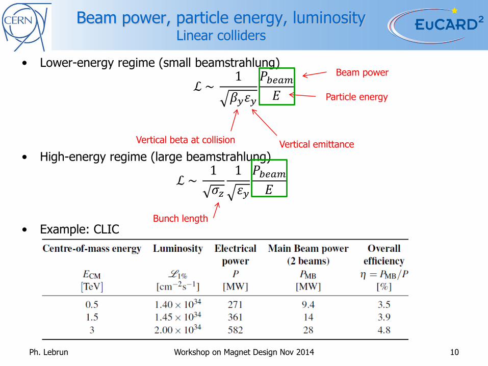
Beam power, particle energy, luminosity Linear colliders
• Lower-energy regime (small beamstrahlung)
ℒ ~ 1
𝛽𝑦휀𝑦
𝑃𝑏𝑒𝑎𝑚𝐸
• High-energy regime (large beamstrahlung)
ℒ ~ 1
𝜎𝑧
1
휀𝑦
𝑃𝑏𝑒𝑎𝑚𝐸
• Example: CLIC
Beam power
Particle energy
Vertical beta at collision Vertical emittance
Bunch length
Ph. Lebrun 10 Workshop on Magnet Design Nov 2014
Page 11
Beam power, particle energy, intensity Circular accelerators
• Beam energy
𝑊𝑏𝑒𝑎𝑚 = 𝑁𝑝𝑢𝑙𝑠𝑒𝐸
• Average beam power
𝑃𝑏𝑒𝑎𝑚 =𝑁𝑝𝑢𝑙𝑠𝑒𝐸
𝑇𝑐𝑦𝑐𝑙𝑒
• Example: SPS (design)
– 𝐸 = 400 GeV
– 𝑁𝑝𝑢𝑙𝑠𝑒 = 1013
– 𝑇𝑐𝑦𝑐𝑙𝑒 = 5.8 s
– 𝑊𝑏𝑒𝑎𝑚 = 640 kJ
– 𝑃𝑏𝑒𝑎𝑚 = 110 kW
Accelerator cycle period
Ph. Lebrun 11 Workshop on Magnet Design Nov 2014
Particles per pulse Particle energy [eV]
Page 12
Stored energy, particle energy, luminosity Circular colliders [1/2]
• For round beams with crossing angle
ℒ =𝑁𝑏
2𝑛𝑏𝑓𝑟𝑒𝑣𝛾
4𝜋𝜀𝑛𝛽∗ 𝐹
• Noting that 𝑊𝑏𝑒𝑎𝑚 = 𝑚0𝑐2𝛾𝑁𝑏𝑛𝑏 = 𝐸𝑁𝑏𝑛𝑏
• Then ℒ =1
4𝜋𝑚0𝑐2 𝑓𝑟𝑒𝑣
𝑁𝑏
𝜀𝑛
𝐹
𝛽∗𝑊𝑏𝑒𝑎𝑚 =
𝛾
4𝜋𝑓𝑟𝑒𝑣
𝑁𝑏
𝜀𝑛
𝐹
𝛽∗𝑊𝑏𝑒𝑎𝑚
𝐸
Particles per bunch
Normalized emittance
Ph. Lebrun 12 Workshop on Magnet Design Nov 2014
Number of bunches
Revolution frequency
Geometrical factor
Beta function at collision
Circumference Collision optics
Injector chain
Page 13
Avg. beam power, particle energy, luminosity Circular colliders [2/2]
• Introducing “average” beam power, i.e. beam stored energy divided by beam lifetime
𝑃𝑎𝑣𝑔 𝑏𝑒𝑎𝑚 =𝑊𝑏𝑒𝑎𝑚
𝜏𝑏𝑒𝑎𝑚~
𝐸ℒ
𝜏𝑏𝑒𝑎𝑚
• Example: LHC nominal
– 𝐸 = 7 TeV
– 𝐼 = 0.58 A
– ℒ = 1.0E34 cm− 2. s
− 1
– 𝑊𝑏𝑒𝑎𝑚 = 362 MJ
– taking 𝜏𝑏𝑒𝑎𝑚 ≈ 10 h,
– then 𝑃𝑎𝑣𝑔 𝑏𝑒𝑎𝑚 ≈ 10 kW
– i.e. about 20 kW for two beams
Ph. Lebrun Workshop on Magnet Design Nov 2014 13
Page 14
Collider COP
• For all types of colliders , the average beam power is proportional to the product of particle energy and luminosity
• We can then define a “collider coefficient of performance” (CoCOP) as the product of collision energy and luminosity
𝐶𝑜𝐶𝑂𝑃 = 2 𝐸 ℒ [E34 TeV. cm− 2. s
− 1]
• The CoCOP can then be compared to the beam power for different machines, and the ratio 𝐶𝑜𝐶𝑂𝑃/𝑃𝑏𝑒𝑎𝑚 [E34 TeV.cm-2.s-1/MW] used to quantify the relation between beam power and collider performance
• Notes
– The CoCOP has the dimension of an inverse cross-section
– The CoCOP may be seen as an attempt to quantify the “physics reach” of the collider. However, it gives the same weight to energy and luminosity, which are both important but not equivalent. A “physics coefficient of performance” (PhyCOP) could be defined by a Cobb-Douglas function
𝑃ℎ𝑦𝐶𝑂𝑃 = 2 𝐸 ℒ𝑛 with 𝑛 < 1
Ph. Lebrun Workshop on Magnet Design Nov 2014 14
Page 15
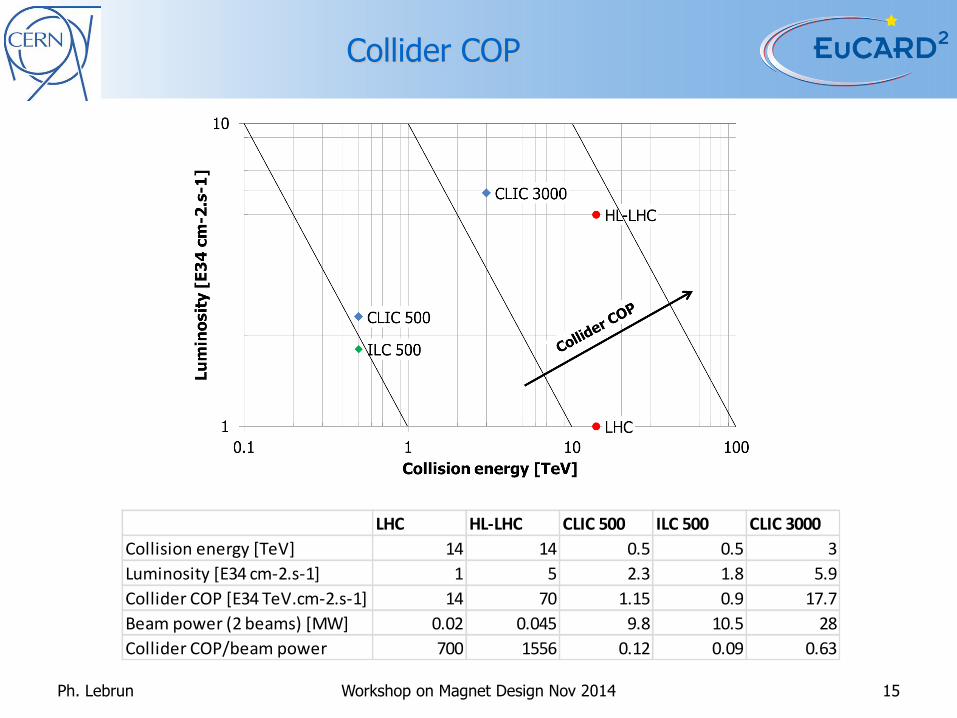
Collider COP
Ph. Lebrun Workshop on Magnet Design Nov 2014 15
LHC HL-LHC CLIC 500 ILC 500 CLIC 3000
Collision energy [TeV] 14 14 0.5 0.5 3
Luminosity [E34 cm-2.s-1] 1 5 2.3 1.8 5.9
Collider COP [E34 TeV.cm-2.s-1] 14 70 1.15 0.9 17.7
Beam power (2 beams) [MW] 0.02 0.045 9.8 10.5 28
Collider COP/beam power 700 1556 0.12 0.09 0.63
Page 16
Collider COP/beam power Note logarithmic scale
Ph. Lebrun Workshop on Magnet Design Nov 2014 16
Page 17
A two-step approach [2/2]
• Understand relations between
– Performance parameters
• Particle energy 𝐸
• Luminosity ℒ
– Beam parameters
• Beam power 𝑃𝑏𝑒𝑎𝑚
• Beam stored energy 𝑊𝑏𝑒𝑎𝑚
• Analyse sources of losses
– “Intrinsic” losses
• Synchrotron radiation
• Beam image currents
• Electron cloud
– Accelerator systems
• RF
• Magnets
• Vacuum
• Beam instrumentation
• …
– Infrastructure
• Electrical distribution
• Cooling & ventilation
• Cryogenics
• …
Ph. Lebrun Workshop on Magnet Design Nov 2014 17
Page 18
Example of analysis CLIC power consumption by technical system
500 GeV A Total 272 MW
1.5 TeV Total 364 MW
3 TeV Total 589 MW
CV: cooling & ventilation, NW: electrical network losses, BIC: beam instrumentation & control
Ph. Lebrun Workshop on Magnet Design Nov 2014 18
Page 19
Collider power and efficiency
Ph. Lebrun Workshop on Magnet Design Nov 2014 19
LHC* HL-LHC* CLIC 500 ILC 500 CLIC 3000
Beams [MW] 0.02 0.045 9.8 10.5 28
Intrinsic [MW] 0.025 0.036
Accelerator systems** [MW] 14.8 14.8 185 96 446
Accelerator efficiency [%] 0.14 0.30 5.30 10.94 6.28
Infrastructure***[MW] 72.4 85.5 71 68 121
Total grid power [MW] 87 101 261 175 573
Grid-to-beam efficiency [%] 0.02 0.04 3.75 6.00 4.88
* excluding injectors
** including beam power
*** including cryogenics
Page 20
Collider efficiencies Note logarithmic scale
Ph. Lebrun Workshop on Magnet Design Nov 2014 20
Page 21
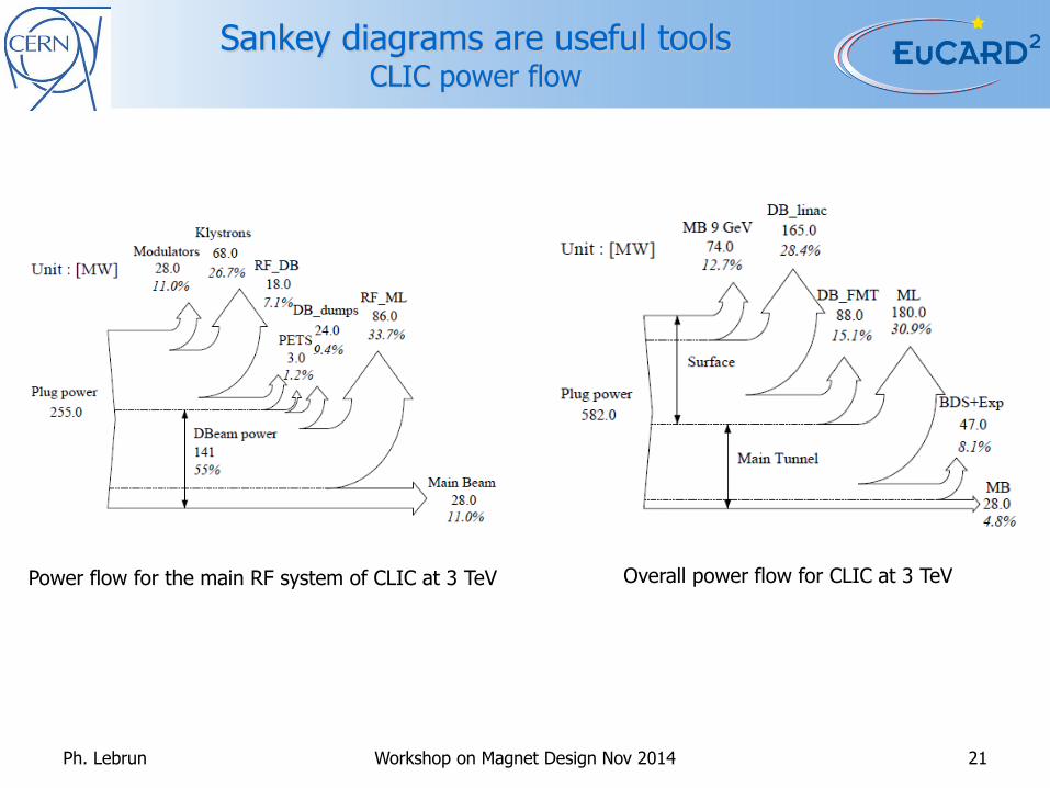
Sankey diagrams are useful tools CLIC power flow
Ph. Lebrun Workshop on Magnet Design Nov 2014 21
Power flow for the main RF system of CLIC at 3 TeV Overall power flow for CLIC at 3 TeV
Page 22
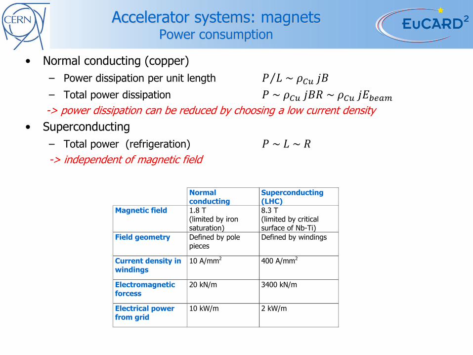
Accelerator systems: magnets Power consumption
• Normal conducting (copper)
– Power dissipation per unit length 𝑃 𝐿 ~ 𝜌𝐶𝑢 𝑗𝐵
– Total power dissipation 𝑃 ~ 𝜌𝐶𝑢 𝑗𝐵𝑅 ~ 𝜌𝐶𝑢 𝑗𝐸𝑏𝑒𝑎𝑚
-> power dissipation can be reduced by choosing a low current density
• Superconducting
– Total power (refrigeration) 𝑃 ~ 𝐿 ~ 𝑅
-> independent of magnetic field
Normal conducting
Superconducting (LHC)
Magnetic field 1.8 T (limited by iron saturation)
8.3 T (limited by critical surface of Nb-Ti)
Field geometry Defined by pole pieces
Defined by windings
Current density in windings
10 A/mm2 400 A/mm2
Electromagnetic forcess
20 kN/m 3400 kN/m
Electrical power from grid
10 kW/m 2 kW/m
Page 23
Magnet systems for circular accelerators Specific power consumption
Superconductivity and higher fields break the canonical
~ 250 kW/GeV specific power consumption of conventional synchrotron magnets
Page 24
Accelerator systems: RF Development of high-efficiency modulators
Useful flat-top Energy 22MW*140μs = 3.08kJ
Rise/fall time energy 22MW*5μs*2/3= 0.07kJ
Set-up time energy 22MW*5μs = 0.09kJ
Pulse efficiency 0.95
Pulse forming system
efficiency
0.98
Charger efficiency 0.96
Power efficiency 0.94
Overall Modulator
efficiency
89%
Ch
arg
er
Pu
lse
Fo
rmin
g
Syste
m (
PF
S)
Modulator
Kly
str
on
Utilit
y g
rid
400/36kV 150kV??kV
D. Nisbet & D. Aguglia
Ph. Lebrun HF 2014 Beijing 24
Page 25
Accelerator systems: RF “Smart” RF loads
• RF-to-DC power conversion
F.Caspers, M. Betz, A. Grudiev & H. Sapotta, Design concepts for RF-DC conversion in particle accelerator systems, IPAC10
Ph. Lebrun Workshop on Magnet Design Nov 2014 25
• High-temperature heat recovery
S. Federmann, M. Betz, F.Caspers, RF loads for energy recovery, IPAC12
Page 26
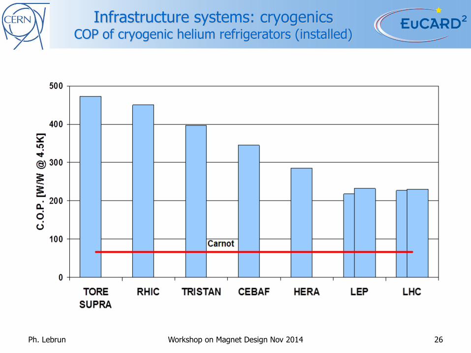
Infrastructure systems: cryogenics COP of cryogenic helium refrigerators (installed)
Ph. Lebrun Workshop on Magnet Design Nov 2014 26
Page 27
Cryogenic refrigeration Efficiency degrades at reduced capacity
Ph. Lebrun Workshop on Magnet Design Nov 2014 27
Page 28
Infrastructure systems: cooling & ventilation Efficiency of heat transport in water vs. air
• Heat to be extracted 𝑄 = 𝑚 𝐶 ∆𝑇
• Mechanical power on coolant 𝑊 =𝑚 ∆𝑃
𝜀 𝜌 with 휀 = circulator efficiency
• Specific power 𝑊 𝑄 = ∆𝑃
𝜀 𝜌 𝐶 ∆𝑇
Ph. Lebrun Workshop on Magnet Design Nov 2014 28
휀 = 0.5
Page 29
Summary Reasons for low efficiency
• For all types of machines, the average beam power is proportional to the product of particle energy and luminosity or delivered particle flux
• The energy-luminosity performance, and possibly the physics reach of a collider can be represented by a single “coefficient of performance”
• The ratio of “coefficient of performance” to beam power quantifies the relation between collider performance and beam parameters: it is lower for single-pass machines than for circular colliders
• “Intrinsic” losses due to basic physics processes add up to the beam power and often exceed it (synchrotron radiation)
• Accelerator systems and infrastructure represent the bulk of electrical power consumption
• Comparing total power consumption and average beam power yields very low values for overall “grid-to-beam” efficiency
• Linear colliders show higher overall “grid-to beam” efficiencies than circular colliders. This partly compensates for their much lower COP/beam power ratio
Ph. Lebrun Workshop on Magnet Design Nov 2014 29
Page 30
Outlook Strategies for better efficiency
• Maximize energy-luminosity performance per unit of beam power
– Minimize circumference for a given energy (high-field magnets)
– Operate at beam-beam limit
– Low-emittance, high-brilliance beams
– Low-beta insertions, small crossing angle (“crabbing”)
– Short bunches (beamstrahlung)
• Contain “intrinsic” losses
– Synchrotron radiation
– Beam image currents
– Electron-cloud
• Optimize accelerator systems
– RF power generation and acceleration (deceleration)
– Low-dissipation magnets (low current density, pulsed, superconducting, permanent)
• Optimize infrastructure systems
– Efficient cryogenics (heat loads, refrigeration cycles & machinery, distribution)
– Limit electrical distribution losses (cables, transformers)
– Absorb heat loads preferably in water rather than air
– Recover and valorise waste heat
Ph. Lebrun Workshop on Magnet Design Nov 2014 30


![Tommy Bouchard-Lebrun Appellant Tommy Bouchard-Lebrun · BOUCHARD-LEBRUN [2011] 3 S.C.R. A court must consider the specific principles that govern the insanity defence in order to](https://static.documents.pub/doc/80x56/605f208776a66f76ad16bf48/tommy-bouchard-lebrun-appellant-tommy-bouchard-lebrun-bouchard-lebrun-2011-3-scr.jpg)


