18
Materials Engineering 2013 Summer Internship Robert Schuld R&D Engineering/ Philips-Dunlee 09/20/13
| Date post: | 13-Jul-2015 |
| Category: |
Technology |
| Upload: | robert-schuld |
| View: | 213 times |
| Download: | 1 times |

Materials Engineering
2013 Summer Internship
Robert Schuld
R&D Engineering/ Philips-Dunlee
09/20/13

Objective 1: Develop new inspection techniques to characterize the surface of ball
bearings to improve the lifetime, reliability and noise of the X-ray tube
Objective 2: Characterize structure of brazed TZM/Graphite sample to find
relations to processing, properties and performance of the material
Objective 3: Perform SolidWorks simulations to analyze the materials and design
of X-ray tube components
Objective 4: Perform a baseline characterization of (MIL-PRF 22191F) plastic
packaging for precision components
Projects

Image Processing Results
Raw Image
Image processing tool used: ImageJ
Measured Characteristics M62 ball bearing
“Use image processing software to quantitatively
measure ball characteristics”

Image Processing Results
Number of Particles
Counted Total particle area (µm2) Average Area (µm2)
% of Total
Area
M62 2640 10959.7 4.15 18.9
0
0.2
0.4
0.6
0.8
1
0 5 10 15 20 25 30
Cu
mu
lati
ve P
rob
abili
ty
Particle Area (µm2)
Cumulative Probability
0
0.05
0.1
0.15
0.2
0.25
0.3
0 5 10 15 20 25 30
Pro
bab
ility
Den
sity
Particle Area (µm2)
Probability Density
“Use image processing software to quantitatively
measure ball characteristics” Measured Particles

EDS Simulation Results
0 1 2 3 4 5 6 7 8 9 10
keV
Experimental Vs Simulation M62 Steel
Ball 1
Simulation
Experiment
C
Fe
Result: EDS simulation can closely predict experimental results
“Use energy-dispersive X-ray spectroscopy (EDS) simulation
software to better understand ball coating”
Mo
W
Cr Cr
V
Fe
Fe
• Used DTSA-II and calibrated simulation detector with Dunlee’s Si(Li) detector

EDS Simulation Results
1000 A Coating 1
100 A Carbon
Steel Ball
5000 A Coating 1
Steel Ball
0
2000
4000
6000
8000
10000
12000
14000
16000
0 2 4 6 8 10
Inte
nsi
ty
Energy (keV)
EDS Spectrum
Coating 1
M62 steel with Coating 1
C
Example 1
Example 2
C/Coating 1 Ratio: 0.0206
Monte Carlo Trajectory Simulation
Program: NIST DTSA-II
1000 A Carbon
0
2000
4000
6000
8000
10000
12000
14000
16000
0 2 4 6 8 10
Inte
nsi
ty
Energy (keV)
EDS Spectrum
C
Coating 1
C/Coating 1 Ratio: 0.0812
“Use energy-dispersive X-ray spectroscopy
(EDS) simulation software to better
understand ball coating”

EDS Simulation Results
1
10
100
1000
0 10 20 30
Log
(Co
atin
g 2
Th
ickn
ess
)
C/Coating 2 Ratio
C/Coating 2 Ratio vs Coating Thickness
0 Angstroms C
100 Angstroms C
1000 Angstroms C
2000 Angstroms C
5000 Angstroms C
0
50
100
150
200
250
0 0.2 0.4 0.6
Co
ati
ng
2
Th
ick
nes
s (A
ng
stro
ms)
C/Fe Ratio
M62 Coating 2 1000A C
“Use energy-dispersive X-ray spectroscopy (EDS)
simulation software to better understand ball coating”
Knowing the C/Fe ratio can help
determine Ag thickness

Characterization of multilayer TZM sample
Characterize the multilayer TZM sample in order to better understand its structure. A larger understanding of the structure will allow a greater understanding of its processing, properties, and performance.
Components to Analyze:
• Composition
• Void and Grain size
• Layer thickness
• Shape and size of microstructure
• Grain orientation
• Eutectic region percent area
Purpose:

Characterization of multilayer TZM sample
EDS Compositional Line Scan Results

Characterization of multilayer TZM sample
Element Wt%
C 3.9
Ti 61.6
Mo 34.5
Element Wt%
C 10.4
Ti 89.6
EDS results
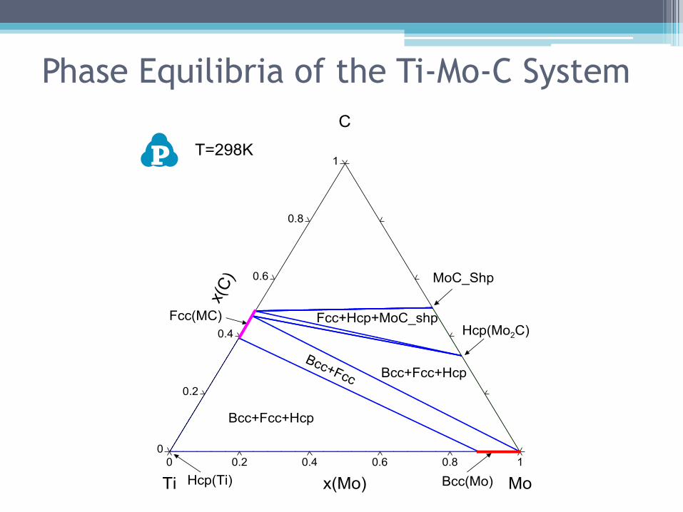
Phase Equilibria of the Ti-Mo-C System

Characterization of multilayer TZM sample
EBSD Results
Different Grains Crystal Orientation
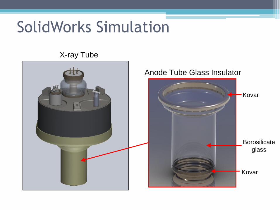
SolidWorks Simulation
Anode Tube Glass Insulator
Borosilicate
glass
Kovar
X-ray Tube
Kovar
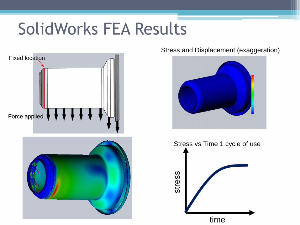
SolidWorks FEA Results Stress and Displacement (exaggeration)
Force applied
Fixed location
time
str
ess
Stress vs Time 1 cycle of use
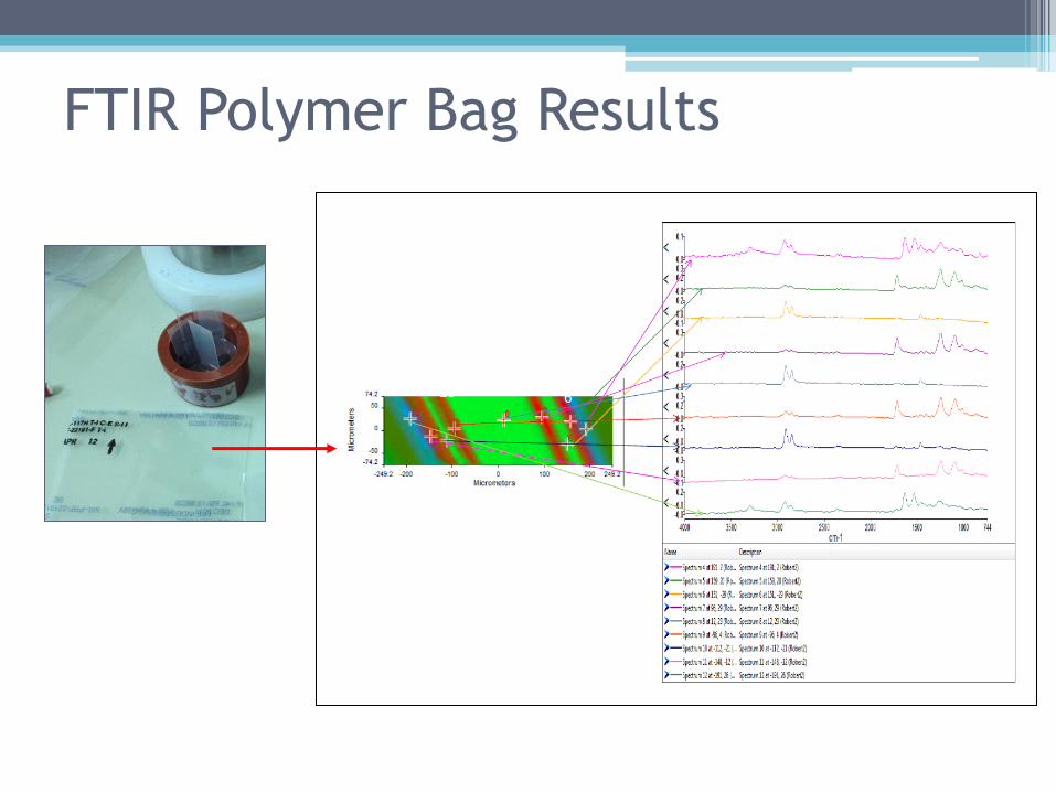
FTIR Polymer Bag Results
4 5
6
7 8 9
10 11 12

FTIR Polymer Bag Results

Conclusion
• Combined several materials characterization tools and techniques
(SEM, FTIR, EDS, EBSD) for analysis of component properties and
microstructure development
• Developed procedures to improve product inspection techniques of
X-ray tube components by using image processing and EDS
simulation software
• Created 3D SolidWorks models for thermo-mechanical stress
analyses of components

Acknowledgments
• Michael Drory
• Rachel Wang


