DU-AG-0018-71 Rev A 4/05/07 GCX Corp Page 1 of 16 Installation Guide Philips MP40/50/60/70 Installation Kit for Penlon Anesthesia Machine The purpose of this guide is to describe installation of MP40/50/60/70 mounting equipment on the anesthesia machine. WARNING: USE OF MOUNTING HARDWARE AND MONITORING COMPONENTS OTHER THAN THOSE DESCRIBED IN THIS DOCUMENT MAY RESULT IN SERIOUS INJURY DUE TO TIPPING OF THE ANESTHESIA MACHINE. Counterweight Kit (Pages 2 – 4) Horizontal Channel (Page 8) Horizontal Mounting Adapter for G5 on Table Top Mount (Page 9) Down Post & Utility Hook (Page 10) Display Mounting Bracket (Pages 11 – 13) Optional - Horizontal Channel Mount for AGM (Pages 14 – 15) Counterweight Kits (Pages 5 – 7)
Transcript
DU-AG-0018-71 Rev A 4/05/07 GCX Corp Page 1 of 16
Installation Guide
Philips MP40/50/60/70 Installation Kit for Penlon Anesthesia Machine The purpose of this guide is to describe installation of MP40/50/60/70 mounting equipment on the anesthesia machine.
WARNING: USE OF MOUNTING HARDWARE AND MONITORING COMPONENTS OTHER THAN THOSE DESCRIBED IN THIS DOCUMENT MAY RESULT IN SERIOUS INJURY DUE TO TIPPING OF THE ANESTHESIA MACHINE.
Counterweight Kit (Pages 2 – 4)
Horizontal Channel (Page 8)
Horizontal Mounting Adapter for G5 on Table Top Mount (Page 9)
Down Post & Utility Hook (Page 10)
Display Mounting Bracket (Pages 11 – 13)
Optional - Horizontal Channel Mount for AGM (Pages 14 – 15)
Counterweight Kits (Pages 5 – 7)
DU-AG-0018-71 Rev A 4/05/07 GCX Corp Page 2 of 16
Installing Counterweight on Bottom of Anesthesia Machine
WARNING! The installation of the two (2) 30 lb. [13.6 kg] Weight Bars requires two (2) people. Failure to heed this warning could result in injury to personnel or damage to equipment. Both Weight Bars in this installation kit must be installed to prevent tipping of the anesthesia machine.
Parts Reference
The following parts and hardware will be used in this installation (hardware not shown):
Tools required: 6 mm Hex Wrench (provided), 3/8'' wrench (not provided). To install the Counterweight, follow instructions in callouts beginning below. Photos are taken from the bottom rear of the machine.
Item # Description Qty
1 Mounting Bracket 2
2 M8 x 30 mm Socket Head Cap Screw (SHCS) 4
3 Weight Bar 2
4 Counterweight Cover 1
5 #10-32 Kep Nut 2
6 6 mm Hex Wrench 1
1
4
3
6
1. Using the 6 mm hex wrench provided, Remove the four (4) existing socket head screws from the bottom of the machine. These mounting holes will be used for attachment of Counterweight Mounting Brackets (next page).
View from Rear of Machine
DU-AG-0018-71 Rev A 4/05/07 GCX Corp Page 3 of 16
2. Using the 6 mm hex wrench provided, fasten Mounting Bracket to each side of machine with two (2) M8 x 30 mm SHCS as shown.
Mounting Bracket
Mounting Brackets
Mounting Bracket (x 2)
3. Carefully lift the first Weight Bar onto the Mounting Brackets as shown above.
Weight Bar should be positioned across Brackets as shown here
Counterweight Bar
DU-AG-0018-71 Rev A 4/05/07 GCX Corp Page 4 of 16
4. Carefully lift second Weight Bar onto top of first Weight Bar.
5. Fit Counterweight Cover over two (2) studs on bottoms of Mounting Brackets. Thread #10-32 kep nuts onto the studs and tighten nuts with a 3/8'' wrench.
Counterweight Cover
DU-AG-0018-71 Rev A 4/05/07 GCX Corp Page 5 of 16
Mounting Counterweights on Right Side of Anesthesia Machine, Rear Channel
The following procedure will performed twice for the mounting of two (2) Counterweights. Parts Reference Two (2) of the following Counterweight Kits are provided (hardware not shown):
Installation Note: Additional hardware (not included in above Counterweight Kit) is required for mounting the Counterweights on the Penlon anesthesia machine. One (1) 3/4'' Slide Spacer, and four (4) #10-32 x 1-1/4'' Pan Head Machine Screws (PHMS) are provided for attaching the Channel Slide to the Mounting Bracket as follows:
1. Pry existing Slide Spacer off the Channel Slide as shown below.
2. Insert the 3/4'' Slide Spacer between the Channel Slide and the Mounting Bracket and fasten parts together with four (4) #10-32 x 1-1/4'' PHMS as shown below.
Item # Description Qty
1 Weight Bar, 30 lbs 1
2 Mounting Bracket 1
3 #10-32 x 1/4'' Flat Head Machine Screw (FHMS), 100º 4
4 Counterweight Cover 1
5 Channel Slide 1
6 Adjustable Stop 1
Pry Existing Spacer off Slide
Channel Slide
3/4'' Slide Spacer
Mounting Bracket
#10-32 x 1-1/4''’ PHMS (4)
1
2
4 5
6
DU-AG-0018-71 Rev A 4/05/07 GCX Corp Page 6 of 16
3. Turn Counterweight Cover upside down and slide the Weight Bar into Cover as shown below. Place the Mounting Bracket over the Weight Bar (Bracket fits inside Cover) and fasten Cover to Bracket with four (4) #10-32 x 1/4'' FHMS.
WARNING! The installation of the two (2) 30 lb. [13.6 kg] Counterweights in the right rear channel requires two (2) people. Failure to heed this warning could result in injury to personnel or damage to equipment. Both Counterweights must be installed to prevent tipping of the anesthesia machine.
4. Insert Slide at bottom of channel and carefully lift counterweight to top of channel. While holding counterweight at top
of channel, install an Adjustable Stop 13'' from bottom of channel. Tighten Adjustable Stop as tightly as possible. Carefully lower Counterweight to rest against the Adjustable Stop.
Counterweight CoverWeight Bar
Mounting Bracket
Hold Counterweight at Top of Channel.
Opening at Bottom of Channel.
Install Adjustable Stop 13'' from Bottom.
13''
Lower Counterweight to Rest against Adjustable Stop.
10-32 x 1/4'' FHMS (2 per Side)
DU-AG-0018-71 Rev A 4/05/07 GCX Corp Page 7 of 16
5. Insert second Counterweight in channel. Lift Counterweight as high as possible, holding in position. Install Adjustable Stop above opening in channel. Tighten Adjustable Stop as tightly as possible, and carefully lower Counterweight until it contacts the Adjustable Stop.
Lower Counterweight to Top of Adjustable Stop
Hold Counterweight as High as Possible.
Install Adjustable Stop above Opening.
DU-AG-0018-71 Rev A 4/05/07 GCX Corp Page 8 of 16
Attaching Horizontal Channel to Top of Machine
Parts Reference
The following parts and hardware are included in this installation kit (parts shown below in Step 1):
Tools Required
Phillips screwdriver (not provided), 7/16'' wrench (not provided). 1. Align Channel with mounting holes shown below and fasten Channel to top of machine with hardware called out below.
Item # Description Qty
1 Channel 1
2 1/4-20 x 1-1/4'' Pan Head Machine Screw (PHMS) 2
3 1/4-20 Kep Nut 2
4 1/4'' Flat Washer 2
Horizontal Channel
1/4-20 x 1-1/4'' PHMS (each side)
1/4-20 Kep Nut (1 per side)
1/4'' Flat Washer (1 per side)
DU-AG-0018-71 Rev A 4/05/07 GCX Corp Page 9 of 16
Mounting G5 in Channel
Parts Reference
The following parts and hardware are included in this installation kit (hardware not shown):
Tools Required
Phillips screwdriver (not provided). Attaching *Philips Table Top Mount to Horizontal Mount Adapter
1. Fasten the Philips-supplied Table Top Mount to the Mounting Adapter with three (3) M6 x 10mm. 2. With two (2) set screws facing oriented toward the rear of the application, slide Horizontal Mount into Channel and
move Mount to desired instrument-mounting position (below left).
3. Tighten two (2) set screws at rear of Horizontal Mount to prevent movement of Mount (below right). 4. Mount G5 in accordance with Philips mounting instructions.
Item # Description Qty
1 Horizontal Mount Adapter 1
2 M6 x 10mm Flat Head Machine Screw (FHMS) 3
Table Top Mount *Supplied by Philips
M6 X 10mm FHMS (3)Horizontal Mount Adapter
Set Screws (Rear of Mount)
Insert Horizontal Mount In Channel
1
DU-AG-0018-71 Rev A 4/05/07 GCX Corp Page 10 of 16
Attaching Down Post and Utility Hook to M-Series Arm
This procedure requires parts from two separate installation kits (Utility Hook Kit + Down Post Kit). Use only the 6'' Post from the Down Post Kit, and use the #10-32 x 7/16'' SHCS (3) to fasten 6'' Post and Utility Hook to M-Series Arm.
Utility Hook Parts Reference
The following parts and hardware are provided for this procedure:
6'' Down Post Parts Reference
The following parts and hardware are provided for this procedure:
Tools Required: 5/32'' hex wrench (provided). 1. Remove plastic bolt cap from Swivel Cup (below left).
2. Using the 5/32'' hex wrench provided, fasten Post and Utility Hook to Swivel Cup with three (3) #10-32 x 7/16'' SHCS as shown below right.
Item # Description Qty
1 Utility Hook 1
2 #10-32 x 7/16'' SHCS 3
3 5/32'' Hex Wrench 1
Item # Description Qty
1 Down Post, 6''
1
Utility Hook
Post
#10-32 x 7/16'' SHCS (3)
M-Series Arm
1
DU-AG-0018-71 Rev A 4/05/07 GCX Corp Page 11 of 16
#10-32 x 3/8''PHMS (2)
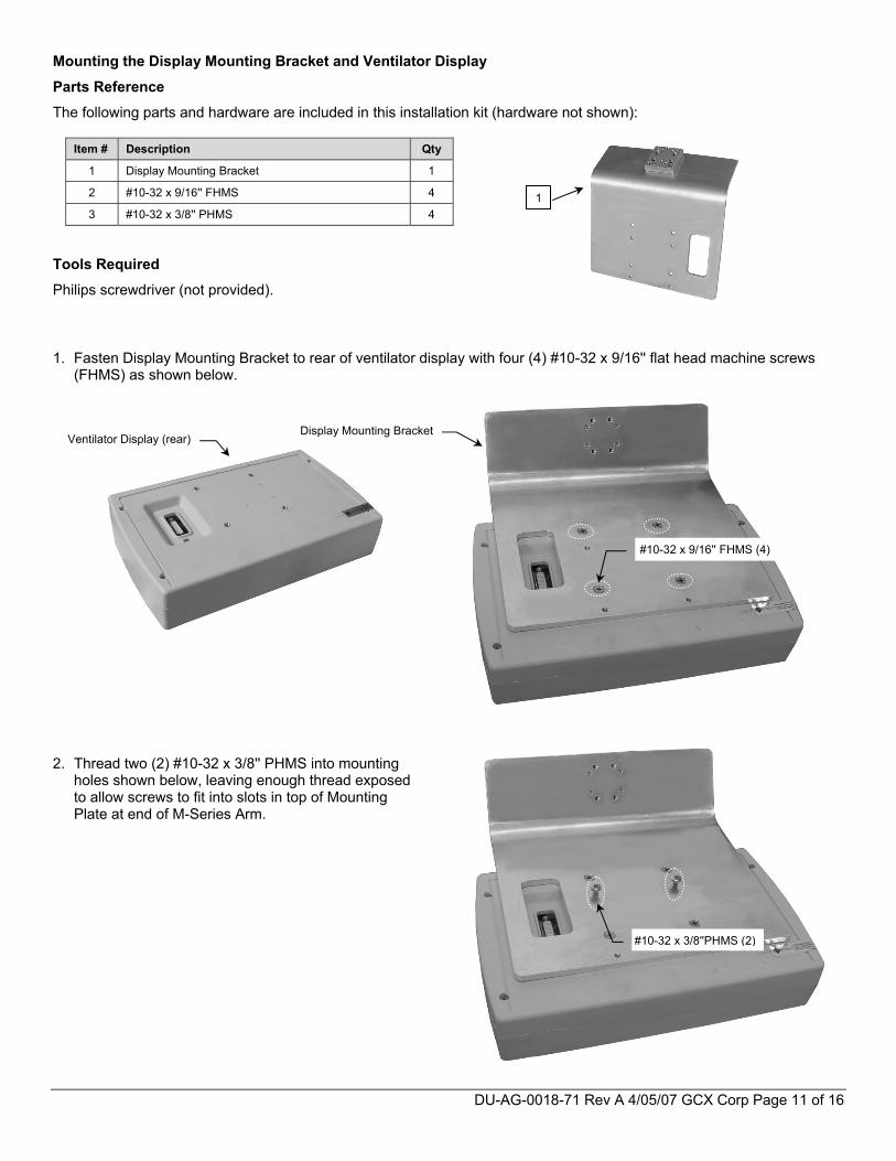
Mounting the Display Mounting Bracket and Ventilator Display
Parts Reference
The following parts and hardware are included in this installation kit (hardware not shown):
Tools Required
Philips screwdriver (not provided).
1. Fasten Display Mounting Bracket to rear of ventilator display with four (4) #10-32 x 9/16'' flat head machine screws (FHMS) as shown below.
2. Thread two (2) #10-32 x 3/8'' PHMS into mounting
holes shown below, leaving enough thread exposed to allow screws to fit into slots in top of Mounting Plate at end of M-Series Arm.
Item # Description Qty
1 Display Mounting Bracket 1
2 #10-32 x 9/16'' FHMS 4
3 #10-32 x 3/8'' PHMS 4 1
Ventilator Display (rear)
#10-32 x 9/16'' FHMS (4)
Display Mounting Bracket
DU-AG-0018-71 Rev A 4/05/07 GCX Corp Page 12 of 16
#10-32 x 3/8''PHMS (2) in Lower Mounting Holes
3. Hang Display Mounting Bracket in upper slots of Mounting Plate as shown below left but do not tighten mounting screws.
4. Install two (2) #10-32 x 3/8'' PHMS into lower mounting holes (shown below) and tighten all four (4) mounting screws.
Tighten all Screws
DU-AG-0018-71 Rev A 4/05/07 GCX Corp Page 13 of 16
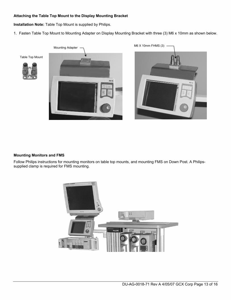
Attaching the Table Top Mount to the Display Mounting Bracket Installation Note: Table Top Mount is supplied by Philips. 1. Fasten Table Top Mount to Mounting Adapter on Display Mounting Bracket with three (3) M6 x 10mm as shown below. Mounting Monitors and FMS
Follow Philips instructions for mounting monitors on table top mounts, and mounting FMS on Down Post. A Philips-supplied clamp is required for FMS mounting.
M6 X 10mm FHMS (3)Mounting Adapter
Table Top Mount
DU-AG-0018-71 Rev A 4/05/07 GCX Corp Page 14 of 16
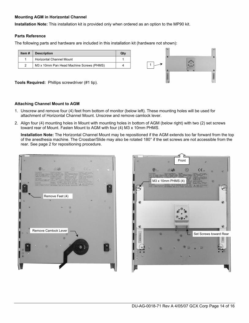
Mounting AGM in Horizontal Channel
Installation Note: This installation kit is provided only when ordered as an option to the MP90 kit.
Parts Reference
The following parts and hardware are included in this installation kit (hardware not shown):
Tools Required: Phillips screwdriver (#1 tip).
Attaching Channel Mount to AGM
1. Unscrew and remove four (4) feet from bottom of monitor (below left). These mounting holes will be used for attachment of Horizontal Channel Mount. Unscrew and remove camlock lever.
2. Align four (4) mounting holes in Mount with mounting holes in bottom of AGM (below right) with two (2) set screws toward rear of Mount. Fasten Mount to AGM with four (4) M3 x 10mm PHMS.
Installation Note: The Horizontal Channel Mount may be repositioned if the AGM extends too far forward from the top of the anesthesia machine. The Crossbar/Slide may also be rotated 180° if the set screws are not accessible from the rear. See page 2 for repositioning procedure.
Item # Description Qty
1 Horizontal Channel Mount 1
2 M3 x 10mm Pan Head Machine Screws (PHMS) 4
Remove Feet (4)
Remove Camlock Lever
1
M3 x 10mm PHMS (4)
Set Screws toward Rear
Front
DU-AG-0018-71 Rev A 4/05/07 GCX Corp Page 15 of 16
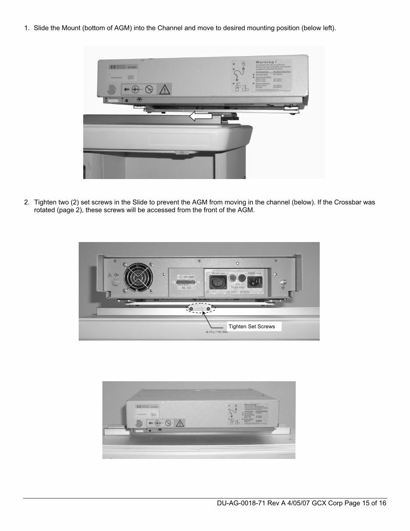
1. Slide the Mount (bottom of AGM) into the Channel and move to desired mounting position (below left).
2. Tighten two (2) set screws in the Slide to prevent the AGM from moving in the channel (below). If the Crossbar was
rotated (page 2), these screws will be accessed from the front of the AGM.
Tighten Set Screws
DU-AG-0018-71 Rev A 4/05/07 GCX Corp Page 16 of 16
Routine Maintenance
Periodically check all mounting hardware. Tighten as necessary for optimal operation. Cleaning the Mounting Assembly CAUTION: GCX makes no claims regarding the efficacy of the listed chemicals or processes as a means for controlling infection. Consult your hospital’s infection control officer or epidemiologist. To clean or sterilize mounted instruments or accessory equipment, refer to the specific instructions delivered with those products. 1. The mounting assembly may be cleaned with most mild, non-abrasive solutions commonly used in the hospital
environment (e.g. diluted bleach, ammonia, or alcohol solutions).
2. The surface finish will be permanently damaged by strong chemicals and solvents such as acetone and trichloroethylene.
3. Do not use steel wool or other abrasive material to clean the mounting assembly.
4. Damage caused by the use of unapproved substances or processes will not be covered by warranty. We recommended that you test any cleaning solution on a small area of the mounting assembly that is not visible to verify compatibility.
5. Never submerge or allow liquids to enter the mounting assemblies. Wipe any cleaning agents off of the mounting assemblies immediately, using a water-dampened cloth. Dry mounting assemblies thoroughly after cleaning.