1 Photoelectric Sensor with Built-in Amplifier E3Z Photoelectric Sensor with Built-in Amplifier with New Connector Options E3Z Compact Sensor Offers Long Sensing Distance and Superior Noise-Immunity D Photo-IC provides long sensing distance: 15 m and 10 m for through-beam, 4 m for retroreflective, and 1 m for diffuse. D Integrated Photo-IC improves noise immunity to interference from inverters and other inductive loads. D New injection molding technology assures IP67 rating to withstand water and dust. D Switch-selectable, Light-ON/Dark-ON operation. D M8 connector-ready and 2 m, pre-wired models. D NPN or PNP output models available. Ordering Information J Sensors Stock Note: Shaded models are normally stocked. Sensing method Light source Appearance Connection method Sensing distance Model NPN output PNP output Through-beam IR/RED Pre-wired 15 m (IR) 10 (RED) E3Z-T61(A) E3Z-T81(A) Connector 10 m (RED) (See Note 1 ) E3Z-T66(A) E3Z-T86(A) Pigtail 3 pin (M8) (See Note 1.) E3Z--T61(A)--M5J E3Z--T81(A)--M5J Pigtail 4 pin (M8) E3Z--T61(A)--M3J E3Z--T81(A)--M3J Pigtail 4 pin (M12) E3Z--T61(A)--M1J E3Z--T81(A)--M1J Polarized fl i RED (See Note 2.) Pre-wired 100 mm to 4 m 100 3 E3Z-R61 E3Z-R81 retroreflective Connector 100 mm to 3 m (See Note 3 ) E3Z-R66 E3Z-R86 Pigtail 3 pin (M8) (See Note 3.) E3Z--R61--M5J E3Z--R81--M5J Pigtail 4 pin (M8) E3Z--R61--M3J E3Z--R81--M3J Pigtail 4 pin (M12) E3Z--R61--M1J E3Z--R81--M1J Diffuse fl i IR Pre-wired 5 to 100 mm ( id i ) E3Z-D61 E3Z-D81 reflective Connector (wide view) E3Z-D66 E3Z-D86 Pigtail 3 pin (M8) E3Z--D61--M5J E3Z--D81--M5J Pigtail 4 pin (M8) E3Z--D61--M3J E3Z--D81--M3J Pigtail 4 pin (M12) E3Z--D61--M1J E3Z--D81--M1J Pre-wired 1m E3Z-D62 E3Z-D82 Connector E3Z-D67 E3Z-D87 Pigtail 3 pin (M8) E3Z--D62--M5J E3Z--D82--M5J Pigtail 4 pin (M8) E3Z--D62--M3J E3Z--D82--M3J Pigtail 4 pin (M12) E3Z--D62--M1J E3Z--D82--M1J Note: 1. Model numbers that end with (A) are red LED versions. 2. The Reflector is sold separately. Select the Reflector model most suited to the application. 3. Sensing distance can be extended to 4 meters when the E39-R1S reflector is used. The sensing distance is 3 meters when the E39-R1 reflector is used.
Transcript
1Photoelectric Sensor with Built-in Amplifier E3Z
Photoelectric Sensor with Built-in Amplifier with New Connector Options
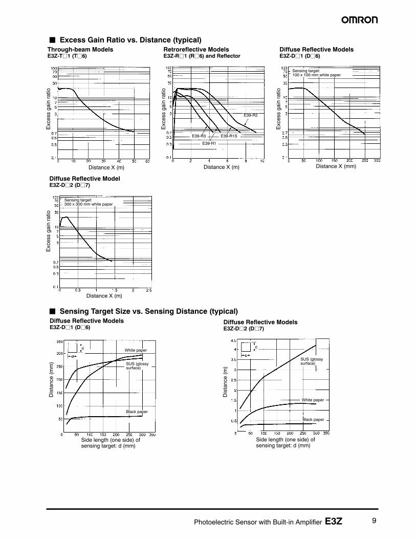
E3ZCompact Sensor Offers Long SensingDistance and SuperiorNoise-ImmunityD Photo-IC provides long sensing distance: 15 m and10 m for through-beam, 4 m for retroreflective, and 1 mfor diffuse.
D Integrated Photo-IC improves noise immunity tointerference from inverters and other inductive loads.
D New injection molding technology assures IP67 ratingto withstand water and dust.
D Switch-selectable, Light-ON/Dark-ON operation.D M8 connector-ready and 2 m, pre-wired models.D NPN or PNP output models available.
Ordering InformationJ Sensors
Stock Note: Shaded models are normally stocked.
Sensing method Light source Appearance Connection method Sensing distance Modelg g pp g
Note: 1. Model numbers that end with (A) are red LED versions.2. The Reflector is sold separately. Select the Reflector model most suited to the application.3. Sensing distance can be extended to 4 meters when the E39-R1S reflector is used. The sensing distance is 3 meters when the
E39-R1 reflector is used.
2 Photoelectric Sensor with Built-in Amplifier E3Z
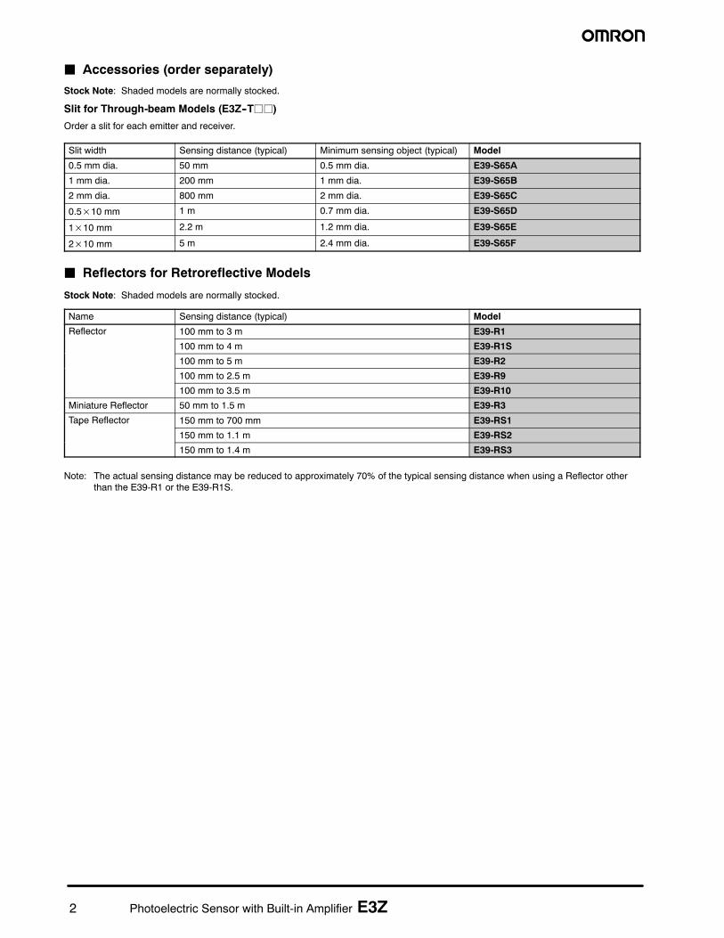
J Accessories (order separately)
Stock Note: Shaded models are normally stocked.
Slit for Through-beam Models (E3Z--Tjj)
Order a slit for each emitter and receiver.
Slit width Sensing distance (typical) Minimum sensing object (typical) Model
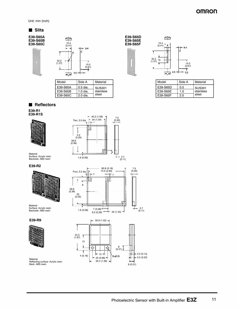
0.5 mm dia. 50 mm 0.5 mm dia. E39-S65A
1 mm dia. 200 mm 1 mm dia. E39-S65B
2 mm dia. 800 mm 2 mm dia. E39-S65C
0.5×10 mm 1 m 0.7 mm dia. E39-S65D
1×10 mm 2.2 m 1.2 mm dia. E39-S65E
2×10 mm 5 m 2.4 mm dia. E39-S65F
J Reflectors for Retroreflective Models
Stock Note: Shaded models are normally stocked.
Name Sensing distance (typical) Model
Reflector 100 mm to 3 m E39-R1
100 mm to 4 m E39-R1S
100 mm to 5 m E39-R2
100 mm to 2.5 m E39-R9
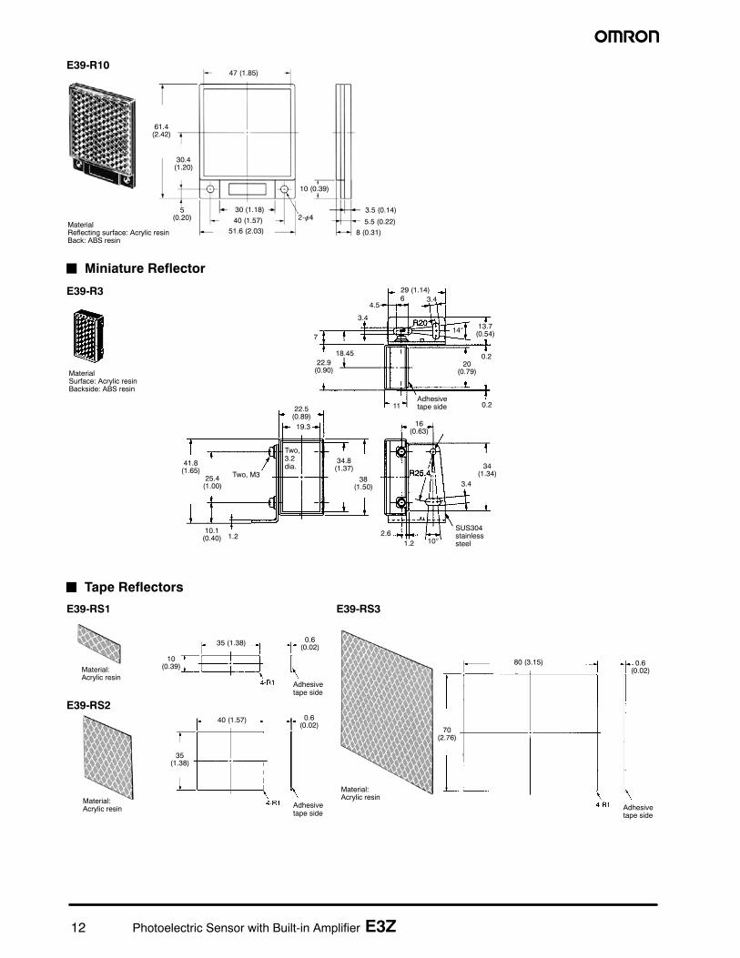
100 mm to 3.5 m E39-R10
Miniature Reflector 50 mm to 1.5 m E39-R3
Tape Reflector 150 mm to 700 mm E39-RS1p
150 mm to 1.1 m E39-RS2
150 mm to 1.4 m E39-RS3
Note: The actual sensing distance may be reduced to approximately 70% of the typical sensing distance when using a Reflector otherthan the E39-R1 or the E39-R1S.
3Photoelectric Sensor with Built-in Amplifier E3Z
J Mounting Brackets
Stock Note: Shaded models are normally stocked.
Appearance Description Model
L-bracket, horizontal E39-L104
L-bracket, vertical E39-L44
Open top,20° angle adjustability
E39-L43
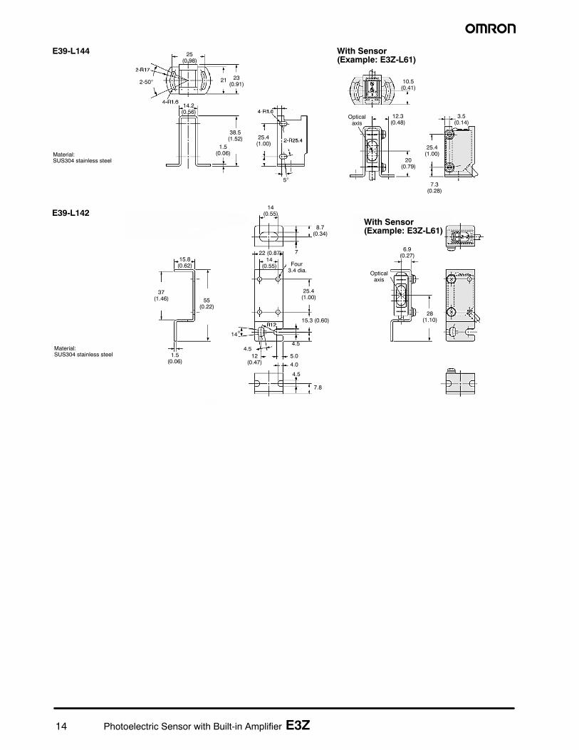
Protected top5° angle adjustability
E39-L144
Compact verticalprotective cover bracket
E39-L142
Vertical protective coverbracket
E39-L98
Appearance Description Model
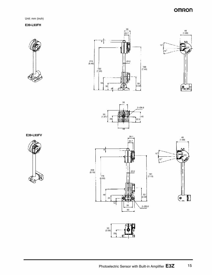
Adjustable height and anglebracket for sensors;horizontal mounting rotatesevery 45 degrees
Mounted to the aluminumframe rails of conveyors,easily adjustable
E39-L93FH
Adjustable height and anglebracket for sensors; verticalmounting rotates every 45degrees
E39-L93FV
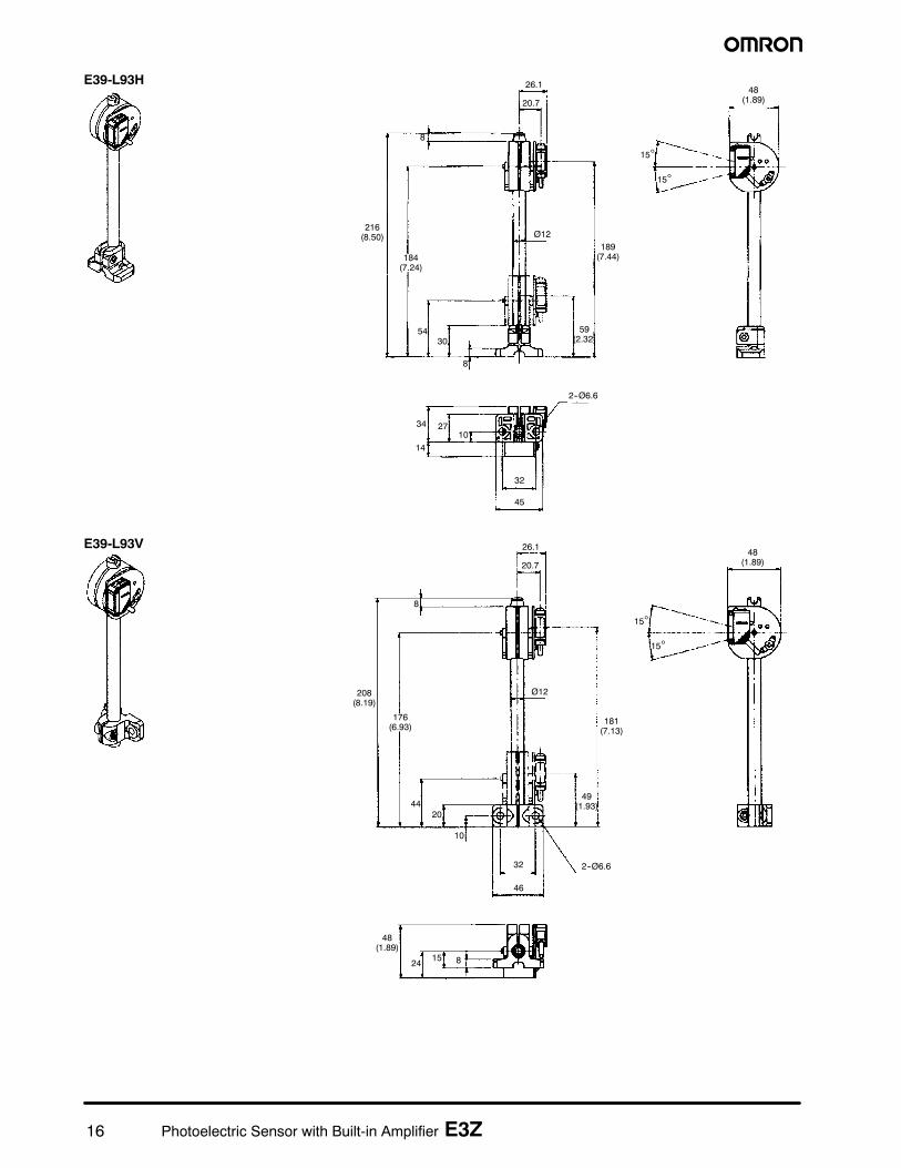
Adjustable height and anglebracket for sensors; fixedhorizontal base mounting
E39-L93H
Adjustable height and anglebracket for sensors; fixedvertical base mounting
E39-L93V
Adjustable height and anglebracket for sensors; freerange of X and Y axis posi-tioning; no base included forvertical post
E39-L93XY
Note: If a through-beam model is used, order two Mounting Brackets — one for the emitter and one for the receiver.
4 Photoelectric Sensor with Built-in Amplifier E3Z
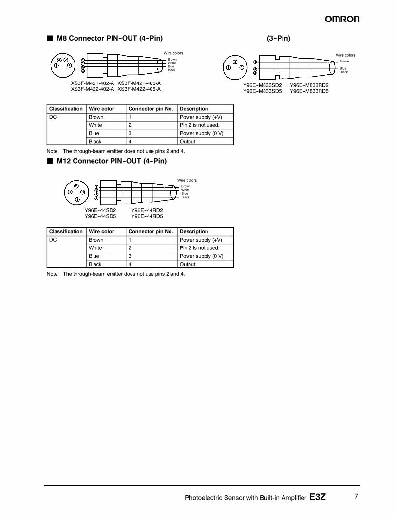
J M8 CONNECTORS
Appearance Cable type Model
Straight 2 m (6.56 ft) Four-wire type XS3F-M421-402-Ag
5 m (16.40 ft)
yp
XS3F-M421-405-A
Right angle 2 m (6.56 ft) XS3F-M422-402-Ag g
5 m (16.40 ft) XS3F-M422-405-A
Straight 2 m (6.56 ft) Three--wire type Y96E--M833SD2g
5 m (16.40 ft)
yp
Y96E--M833SD5
Right angle 2 m (6.56 ft) Y96E--M833RD2g g
5 m (16.40 ft) Y96E--M833RD5
J M12 CONNECTORS
Appearance Cable type Model
Straight 2 m (6.56 ft) Four-wire type Y96E--44SD2g
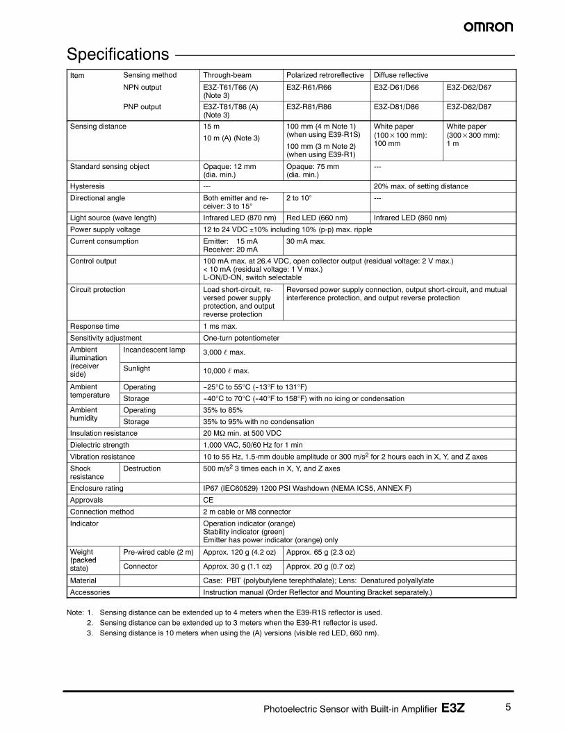
Directional angle Both emitter and re-ceiver: 3 to 15°
2 to 10° ---
Light source (wave length) Infrared LED (870 nm) Red LED (660 nm) Infrared LED (860 nm)
Power supply voltage 12 to 24 VDC ±10% including 10% (p-p) max. ripple
Current consumption Emitter: 15 mAReceiver: 20 mA
30 mA max.
Control output 100 mA max. at 26.4 VDC, open collector output (residual voltage: 2 V max.)< 10 mA (residual voltage: 1 V max.)L-ON/D-ON, switch selectable
Circuit protection Load short-circuit, re-versed power supplyprotection, and outputreverse protection
Reversed power supply connection, output short-circuit, and mutualinterference protection, and output reverse protection
Indicator Operation indicator (orange)Stability indicator (green)Emitter has power indicator (orange) only
Weight(packed
Pre-wired cable (2 m) Approx. 120 g (4.2 oz) Approx. 65 g (2.3 oz)(packedstate) Connector Approx. 30 g (1.1 oz) Approx. 20 g (0.7 oz)
Material Case: PBT (polybutylene terephthalate); Lens: Denatured polyallylate
Accessories Instruction manual (Order Reflector and Mounting Bracket separately.)
Note: 1. Sensing distance can be extended up to 4 meters when the E39-R1S reflector is used.2. Sensing distance can be extended up to 3 meters when the E39-R1 reflector is used.3. Sensing distance is 10 meters when using the (A) versions (visible red LED, 660 nm).
6 Photoelectric Sensor with Built-in Amplifier E3Z
Nomenclature
Diffuse-reflective ModelsE3Z-D6j
Stability indicator (green)
Operation selector
Operation indicator (orange)
Sensitivity adjuster
Through-beam ModelsE3Z-T6j Receiver
Retroreflective ModelsE3Z-R6j
OperationJ Output Circuits
Model E3Z-T61/-T66/-R61/-R66/-D61/-D66/-D62/-D67
NPN output Through-beam receiverRetroreflective modelDiffuse reflective model
Through-beam emitter
Operationindicator Stability
indicator
Maincircuit
Orange Green 100 mAmax.
Load(Relay)
Brown
Black
Blue
Control output
12 to 24 VDC
0 V
Power indicator (orange)
Maincircuit 12 to 24 VDC
Brown
Blue
Model E3Z-T81/-T86/-R86/-D81/-D86/-D82/-D87
PNP output Through-beam receiverRetroreflective modelDiffuse reflective model
13Photoelectric Sensor with Built-in Amplifier E3Z
J Mounting Brackets
With Mounting Bracket(E3Z-D62)
E39-L43
With Mounting Bracket(E3Z-D62)
Material:SUS304stainless steel
Material:SUS304stainless steel
E39-L104
Two, 3.2 dia. Two, M3
29 (1.14)
13.7(0.54)
13.7(0.54)
7(0.28)
29 (1.14)
16(0.63)
39(1.54)
8.8 (0.35)
38.3(1.51)
1.2(0.05)
25.4(1.00)
Opticalaxis
37.8
Two, M3
Four, 3.2 dia.
Opticalaxis
13(0.51)
3.5(0.14)
30 (1.18)3.5
(0.14)
7.5 (0.3) 15(0.59)
25.4(1.00) 40
(1.57)
30 (1.18)3.5(0.14)
3.5(0.14)
40(1.57)
15(0.59)
7.5(0.3)
25.4(1.00)
1.2(0.05)
Unit: mm (inch)
31(1.22)
20(0.79)
13(0.51)
E39-L44
Material:SUS304stainless steel
With Mounting Bracket(E3Z-D62)
Opticalaxis
Two,M3
3.2 dia.
16.2(0.64)
8.7(0.34)
1.2 (0.05)9
(0.35)
18(0.71)
23.2(0.91)
31.2(1.23)
36(1.42)
36(1.42)
31.2(1.23)
23.2(0.91)
25.4(1.00)
8.7(0.34) 16.2
(0.64)
18(0.71)
9(0.35)
20(0.79)
35.3(1.39)
31(1.22)
14.1(0.56)
10.8(0.43)
14 Photoelectric Sensor with Built-in Amplifier E3Z
Material:SUS304 stainless steel
25(0.98)
23(0.91)
14.2(0.56)
38.5(1.52)
1.5(0.06)
25.4(1.00)
Opticalaxis
2-50°
5°
21
20(0.79)
10.5(0.41)
12.3(0.48)
3.5(0.14)
25.4(1.00)
7.3(0.28)
With Sensor(Example: E3Z-L61)
E39-L144
Material:SUS304 stainless steel
15.8(0.62)
14(0.55)
8.7(0.34)
722 (0.87)
55(0.22)
37(1.46)
1.5(0.06)
14(0.55)
25.4(1.00)
15.3 (0.60)
4.5
4.5
4.0
7.8
12(0.47)
5.0
6.9(0.27)
28(1.10)
14°
Opticalaxis
Four3.4 dia.
4.5
With Sensor(Example: E3Z-L61)
E39-L142
15Photoelectric Sensor with Built-in Amplifier E3Z
Unit: mm (inch)
E39-L93FH
215(8.46)
183(7.20)
48(1.89)
15°
15°
8
54
306
59(2.32)
188(7.40)
Ø12
4522.526
50(1.97)
35
2--Ø6.6
26
20.7
48
E39-L93FV
208(8.19)
176(6.93)
15°
15°
8
48
24
12
53(2.09)
181(7.13)
Ø12
48(1.89)
22.5
29
53(2.09)
35 2--Ø6.6
50
26.1
20.7
16 Photoelectric Sensor with Built-in Amplifier E3Z
E39-L93H
216(8.50)
184(7.24)
15°
15°
8
5430
8
59(2.32)
189(7.44)
Ø12
48(1.89)
45
32
34
2--Ø6.6
14
26.1
20.7
2710
E39-L93V
208(8.19)
176(6.93)
15°
15°
8
4420
10
49(1.93)
181(7.13)
Ø12
48(1.89)
815
46
2--Ø6.6
48(1.89)
26.1
20.7
32
24
17Photoelectric Sensor with Built-in Amplifier E3Z
Unit: mm (inch)
E39-L93XY197(7.76)
189(7.44)
15°15°
40(1.51)
165
8
Ø12
20
3515
170(6.69)
8
21 26
2448
213(8.39)
Ø12
22
11
Note: The E39-L93XY consists of a vertical post, x-y joint, 2 nuts, 2 bolts and sensor mounting attachment. There is no base for the bot-tom of the vertical post.
E39-L98
Material:SUS304 stainless steel
Mounting HolesTwo, M6
56 dia.(2.2)
Screw provided61(2.4)
16(0.63)
56 (2.2)
34 (1.34)
20(0.79)
(1.73¦0.01)
25.4(1.00)
35.3(5.33)
18 Photoelectric Sensor with Built-in Amplifier E3Z
J M8 Connector Cordsets (3--Pin)
StraightY96E--M833SD2Y96E--M833SD5
Right AngleY96E--M833RD2Y96E--M833RD5
Ø.39” REF[10.00mm]
M8x1[4.06mm].16” REF
[31.00mm]1.22” REF .75” REF
[19.05mm]
LENGTH
[18.25mm].72” REF
[10.00mm]Ø.39” REF
M8x1
[26.50mm]1.04” REF
[4.06mm].16” REF
.75” REF[19.05mm]
LENGTH
StraightXS3F-M421-402-A (L=2 m)XS3F-M421-405-A (L=5 m)
Right AngleXS3F-M422-402-A (L=2 m)XS3F-M422-405-A (L=5 m)
J M8 Connector Cordsets (4--Pin) 4 (0.16) dia.
9 dia.(0.35)
21.5(0.85)
31.4(1.24)
50 (1.97)30
20.5(0.81)
23.1(0.91)
4 (0.16) dia.
50 (1.97)
9 (0.35) dia.
2.150.5
3.4
1.95
30 5
5
J M12 Connector Cordsets (4--Pin)
StraightY96E--44SD2 (L=2 m)Y96E--44SD5 (L=2 m)
Right AngleY96E--44RD2 (L=2 m)Y96E--44RD5 (L=2 m)
14.7(0.58)
14.7(0.58)
46.74 (1.84)
31.24(1.23)
M12thread
M12thread
Gold/palladium/nickel--platedbrass contaccts
1 -- Brown +V
4 -- Black Output
3 -- Blue 0V
2 -- White Not UsedGold/palladium/nickel--platedbrass contaccts
19Photoelectric Sensor with Built-in Amplifier E3Z
PrecautionsTo ensure safe sensor operation, please follow the followingprecautions:
J WiringPower Supply Voltage
Make sure that the power supply to the Sensor is within the ratedvoltage range.
Load Short-circuiting
Do not short-circuit the load, or the Sensor may be damaged.
Polarity
Correct polarity wiring is required to prevent damage to thesensor.
Connection Without Load
Do not connect power supply to the Sensor with no loadconnected, or the internal elements may explode or burn.
J Operating EnvironmentDo not use the Sensor in locations with explosive or flammablegas.
J SettingsPower Reset Time
The Sensor is ready to operate 100 ms after the Sensor is turnedON. If the load and Sensor are connected to independent powersupplies respectively, be sure to turn ON the Sensor beforeturning the load ON.
J ConnectionsM8 Metal Connector
• Turn off power before disconnecting the sensor.• Remove the connector cover before connecting or discon-
necting the metal connector.• Secure the connector cover by hand. Do not use any pliers,
or the connector may be damaged.• The proper tightening torque range is between 0.3 and 0.4
N S m. Be sure to tighten the connector securely in order tomaintain the the specified degree of protection and to keepthe connector from loosening due to vibration.
J MountingUse M3 screws to mount the sensor and tighten each screw to amaximum torque of 0.53 N S m.
20 Photoelectric Sensor with Built-in Amplifier E3Z
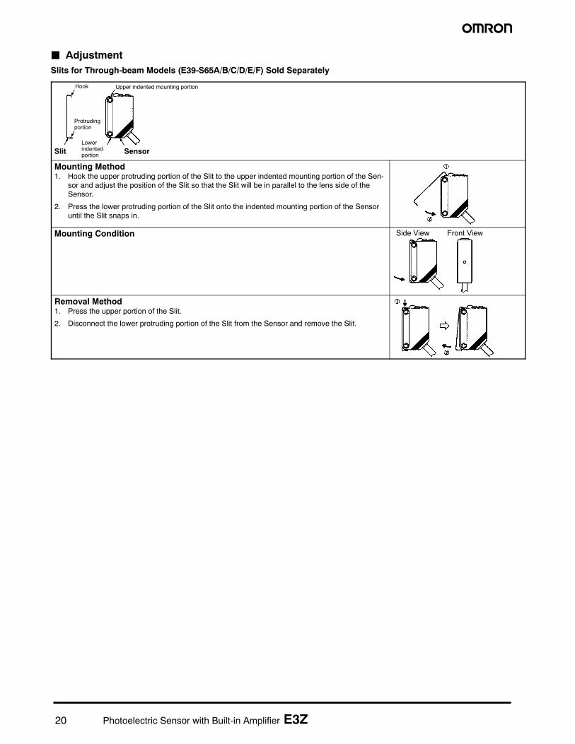
J AdjustmentSlits for Through-beam Models (E39-S65A/B/C/D/E/F) Sold Separately
Hook
Protrudingportion
Lowerindentedportion
Upper indented mounting portion
SensorSlit
Mounting Method1. Hook the upper protruding portion of the Slit to the upper indented mounting portion of the Sen-
sor and adjust the position of the Slit so that the Slit will be in parallel to the lens side of theSensor.
2. Press the lower protruding portion of the Slit onto the indented mounting portion of the Sensoruntil the Slit snaps in.
Mounting Condition Side View Front View
Removal Method1. Press the upper portion of the Slit.
2. Disconnect the lower protruding portion of the Slit from the Sensor and remove the Slit.
21Photoelectric Sensor with Built-in Amplifier E3Z
Certain Terms and Conditions of Sale1 Offer; Acceptance. These terms and conditions (these ”Terms”) are deemed part of
all catalogs, manuals or other documents, whether electronic or in writing, relatingto the sale of goods or services (collectively, the ”Goods”) by Omron ElectronicsLLC and its subsidiary companies (“Seller”). Seller hereby objects to any terms orconditions proposed in Buyer’s purchase order or other documents which are in-consistent with, or in addition to, these Terms. Please contact your Omron repre-sentative to confirm any additional terms for sales from your Omron company.
2 Prices. All prices stated are current, subject to change without notice by Seller.Buyer agrees to pay the price in effect at time of shipment.
3 Discounts. Cashdiscounts, if any,will apply only on the net amount of invoices sentto Buyer after deducting transportation charges, taxes and duties, and will be al-lowed only if (i) the invoice is paid according to Seller’s payment terms and (ii) Buy-er has no past due amounts owing to Seller.
4 Orders. Seller will accept no order less than $200 net billing.5 Governmental Approvals. Buyer shall be responsible for, and shall bear all costs
involved in, obtaining any government approvals required for the importation orsale of the Goods.
6 Taxes. All taxes, duties and other governmental charges (other than general realproperty and income taxes), including any interest or penalties thereon, imposeddirectly or indirectly onSeller or required to be collected directly or indirectly bySell-er for the manufacture, production, sale, delivery, importation, consumption or useof theGoodssold hereunder (including customsdutiesandsales, excise, use, turn-over and license taxes) shall be charged to and remitted by Buyer to Seller.
7 Financial. If the financial position of Buyer at any time becomes unsatisfactory toSeller, Seller reserves the right to stop shipments or require satisfactory security orpayment in advance. If Buyer fails tomakepayment or otherwise complywith theseTermsor any related agreement, Sellermay (without liability and in addition to otherremedies) cancel any unshipped portion of Goods sold hereunder and stop anyGoods in transit until Buyer pays all amounts, including amounts payable hereun-der, whether or not then due, which are owing to it by Buyer. Buyer shall in anyevent remain liable for all unpaid accounts.
8 Cancellation; Etc. Orders are not subject to rescheduling or cancellation unlessBuyer indemnifies Seller fully against all costs or expenses arising in connectiontherewith.
9 ForceMajeure. Seller shall not be liable for any delay or failure in delivery resultingfromcausesbeyond its control, including earthquakes, fires, floods, strikes or otherlabor disputes, shortage of labor ormaterials, accidents tomachinery, acts of sabo-tage, riots, delay in or lack of transportation or the requirements of any governmentauthority.
10 Shipping; Delivery. Unless otherwise expressly agreed in writing by Seller:a. Shipments shall be by a carrier selected by Seller;b. Such carrier shall act as the agent of Buyer and delivery to such carrier shall
constitute delivery to Buyer;c. All sales and shipments ofGoods shall beFOBshipping point (unless other-
wise stated inwriting bySeller), at which point title to and all risk of loss of theGoods shall pass from Seller to Buyer, provided that Seller shall retain a se-curity interest in the Goods until the full purchase price is paid by Buyer;
d. Delivery and shipping dates are estimates only.e. Seller will package Goods as it deems proper for protection against normal
handling and extra charges apply to special conditions.11 Claims. Any claim by Buyer against Seller for shortage or damage to the Goods
occurring before delivery to the carrier must be presented in writing to Sellerwithin 30 days of receipt of shipment and include the original transportation billsigned by the carrier noting that the carrier received the Goods from Seller inthe condition claimed.
12 Warranties. (a) Exclusive Warranty. Seller’s exclusive warranty is that theGoods will be free from defects in materials and workmanship for a period oftwelve months from the date of sale by Seller (or such other period expressed in
writing by Seller). Seller disclaims all other warranties, express or implied. (b)Limitations. SELLER MAKES NO WARRANTY OR REPRESENTATION,EXPRESS OR IMPLIED, ABOUT NON--INFRINGEMENT, MERCHANTABILITYOR FITNESS FOR A PARTICULAR PURPOSE OF THE GOODS. BUYERACKNOWLEDGES THAT IT ALONE HAS DETERMINED THAT THE GOODSWILL SUITABLY MEET THE REQUIREMENTS OF THEIR INTENDED USE.Seller further disclaims all warranties and responsibility of any type for claims orexpenses based on infringement by the Goods or otherwise of any intellectualproperty right. (c) Buyer Remedy. Seller’s sole obligation hereunder shall be toreplace (in the form originally shipped with Buyer responsible for labor chargesfor removal or replacement thereof) the non--complying Good or, at Seller’selection, to repay or credit Buyer an amount equal to the purchase price of theGood; provided that in no event shall Seller be responsible for warranty, repair,indemnity or any other claims or expenses regarding the Goods unless Seller’sanalysis confirms that the Goods were properly handled, stored, installed andmaintained and not subject to contamination, abuse, misuse or inappropriatemodification. Return of any goods by Buyer must be approved in writing bySeller before shipment. Seller shall not be liable for the suitability or unsuitabil-ity or the results from the use of Goods in combination with any electrical orelectronic components, circuits, system assemblies or any other materials orsubstances or environments. Any advice, recommendations or informationgiven orally or in writing, are not to be construed as an amendment or additionto the above warranty.
13 Damage Limits; Etc. SELLER SHALL NOT BE LIABLE FOR SPECIAL, INDI-RECT OR CONSEQUENTIAL DAMAGES, LOSS OF PROFITS OR PRODUC-TION OR COMMERCIAL LOSS IN ANY WAY CONNECTED WITH THEGOODS, WHETHER SUCH CLAIM IS BASED IN CONTRACT, WARRANTY,NEGLIGENCE OR STRICT LIABILITY. Further, in no event shall liability ofSeller exceed the individual price of the Good on which liability is asserted.
14 Indemnities. Buyer shall indemnify and hold harmless Seller, its affiliates and itsemployees from and against all liabilities, losses, claims, costs and expenses(including attorney’s fees and expenses) related to any claim, investigation,litigation or proceeding (whether or not Seller is a party) which arises or isalleged to arise from Buyer’s acts or omissions under these Terms or in any waywith respect to the Goods. Without limiting the foregoing, Buyer (at its ownexpense) shall indemnify and hold harmless Seller and defend or settle anyaction brought against Seller to the extent that it is based on a claim that anyGood made to Buyer specifications infringed intellectual property rights ofanother party.
15 Property; Confidentiality. The intellectual property embodied in the Goods is theexclusive property of Seller and its affiliates and Buyer shall not attempt toduplicate it in any way without the written permission of Seller. Notwithstandingany charges to Buyer for engineering or tooling, all engineering and tooling shallremain the exclusive property of Seller. All information and materials suppliedby Seller to Buyer relating to the Goods are confidential and proprietary, andBuyer shall limit distribution thereof to its trusted employees and strictly preventdisclosure to any third party.
16 Miscellaneous. (a) Waiver. No failure or delay by Seller in exercising any rightand no course of dealing between Buyer and Seller shall operate as a waiver ofrights by Seller. (b) Assignment. Buyer may not assign its rights hereunderwithout Seller’s written consent. (c) Amendment. These Terms constitute theentire agreement between Buyer and Seller relating to the Goods, and noprovision may be changed or waived unless in writing signed by the parties. (d)Severability. If any provision hereof is rendered ineffective or invalid, suchprovision shall not invalidate any other provision. (e) Setoff. Buyer shall haveno right to set off any amounts against the amount owing in respect of thisinvoice. (f) As used herein, “including” means “including without limitation”.
Certain Precautions on Specifications and Use1. Suitability of Use. Seller shall not be responsible for conformity with any stan-
dards, codes or regulations which apply to the combination of the Good in theBuyer’s application or use of the Good. At Buyer’s request, Seller will provideapplicable third party certification documents identifying ratings and limitationsof use which apply to the Good. This information by itself is not sufficient for acomplete determination of the suitability of the Good in combination with the endproduct, machine, system, or other application or use. The following are someexamples of applications for which particular attention must be given. This isnot intended to be an exhaustive list of all possible uses of this Good, nor is itintended to imply that the uses listed may be suitable for this Good:(i) Outdoor use, uses involving potential chemical contamination or electricalinterference, or conditions or uses not described in this document.(ii) Energy control systems, combustion systems, railroad systems, aviationsystems, medical equipment, amusement machines, vehicles, safety equip-ment, and installations subject to separate industry or government regulations.(iii) Systems, machines and equipment that could present a risk to life or prop-erty. Please know and observe all prohibitions of use applicable to this Good.NEVER USE THE PRODUCT FOR AN APPLICATION INVOLVING SERIOUSRISK TO LIFE OR PROPERTY WITHOUT ENSURING THAT THE SYSTEMAS A WHOLE HAS BEEN DESIGNED TO ADDRESS THE RISKS, AND THATTHE SELLER’S PRODUCT IS PROPERLY RATED AND INSTALLED FORTHE INTENDED USE WITHIN THE OVERALL EQUIPMENT OR SYSTEM.
2. Programmable Products. Seller shall not be responsible for the user’s program-ming of a programmable Good, or any consequence thereof.
3. Performance Data. Performance data given in this catalog is provided as aguide for the user in determining suitability and does not constitute a warranty.It may represent the result of Seller’s test conditions, and the user must corre-late it to actual application requirements. Actual performance is subject to theSeller’s Warranty and Limitations of Liability.
4. Change in Specifications. Product specifications and accessories may bechanged at any time based on improvements and other reasons. It is our prac-tice to change part numbers when published ratings or features are changed, orwhen significant construction changes are made. However, some specificationsof the Good may be changed without any notice. When in doubt, special partnumbers may be assigned to fix or establish key specifications for your applica-tion. Please consult with your Seller’s representative at any time to confirmactual specifications of purchased Good.
5. Errors and Omissions. The information in this catalog has been carefullychecked and is believed to be accurate; however, no responsibility is assumedfor clerical, typographical or proofreading errors, or omissions.
22 Photoelectric Sensor with Built-in Amplifier E3Z
Cat. No. E308--E3--3 10/04 Specifications subject to change without notice. Printed in U.S.A.
OMRON ELECTRONICS LLCOne East Commerce DriveSchaumburg, IL 60173
NOTE: DIMENSIONS SHOWN ARE IN MILLIMETERS. To convert millimeters to inches divide by 25.4.
For US technical support or other inquiries:800-556--6766
Complete “terms and conditions of sale” for product purchase and use are on Omron’s website atwww.omron.com/oei -- under the “About Us” tab in the Legal Matters section.
Mouser Electronics
Authorized Distributor
Click to View Pricing, Inventory, Delivery & Lifecycle Information: Omron:


![Ultra-slim Photoelectric Sensor [Amplifier Built-in] EX-10 ... · MS-EX10-3 L-shaped mounting bracket sensor [Cold rolled carbon steel (SPCC)] (The thru-beam type sensor needs two](https://static.documents.pub/doc/80x56/60568e4c115864761f627525/ultra-slim-photoelectric-sensor-amplifier-built-in-ex-10-ms-ex10-3-l-shaped.jpg)