29
Photoguns development for EIC and cooling Erdong Wang P3 workshop November 10-12, 2021

Photoguns developmentfor EIC and cooling
Erdong Wang
P3 workshopNovember 10-12, 2021

EIC Electron sources requirements
2
Ecm = 20 GeV -141 GeVHigh luminosity goal: L = 1034cm-2s-1
Design based on existing RHIC,RHIC is well maintained, operating at its peak
•Hadron storage ring 40-275 GeV (existing)•RHIC Yellow(Blue) Ring•Many bunches, 1160 @ 1A beam current•Bright beam emittance•Strong hadron cooling (new)
•Electron storage ring (2.5–18 GeV, new)•Many bunches,•Large beam current (2.5 A) 10 MW S.R. power•s.c. RF cavities
•Electron rapid cycling synchrotron (new)• High charge polarized pre-injector•Spin transparent due to high periodicity
100 mA, 1 nC high brightness electron source, lifetime >1 week
7nC, 56 nA high polarization electron source, lifetime > 2 weeks

Electron gun development at RHIC/EIC
3
Today
FY 2016 FY 2017 FY 2018 FY 2019 FY 2020 FY 2021
113 MHz SRF gunK2CsSb
Commissioning Operation
Commissioning Operation R&D
400 kV HVDC gunK2CsSb
Commissioning350 kV HVDC gunGaAs@780nm

Pre-proposal, DE-FOA-0001664 V. N. Litvinenko, Stony Brook University
Page 3 of 9!
Our SRF gun, see Fig. 2, is unique since it operates at very low frequency. The later provides condition for photo-electron to be generated at the peak of the accelerating field (10-20 MV/m electric field at the photocathode surface). In contrast, a high frequency SRF gun at Rossendorf necessitates electron being ejected from photocathode at very low field (e.g. just 15 degrees from the zero-crossing, see [6] for details). Additional simplification from low frequency is that our SRF gun operates at 4K, which does not require a sophisticated 2K liquid He system.
Fig. 2. The 113 MHz SRF photo-electron gun with its cathode manipulation system. The room temperature hollow Cu stalk is inserted inside 4K superconducting gun cavity. The stalk has an impedance transformer and serves as a half-wave choke shorted outside the cryostat. The cathode magnetic manipulator system has three UHV arms to transport the cathode pucks (Fig.3a) from a storage tank (called a garage up to 3 pucks stored inside it) into the gun cavity (Fig.3b). The long arm delivers the cathode to the end of the stalk (Fig. 3b), where it is grounded to the stalk by RF fingers. Controlling the depth of the stalk insertion with respect to the cavity nose allow us to control focusing strength near the cathode surface. The later is used to control the beam quality from this SRF gun.
(a) (b)
Fig. 3. Details of the room-temperature stalk and photocathode system of our SRF gun: (a) a polished cathode Mo puck on the tip of the cathode manipulator with RF fingers for cathode grounding. Grooves at the sides of the cathode puck are used by manipulator system to grab and mount it; (b) a room temperature hollow Cu quarter-wave stalk with water channel, used for both cooling and heating, is inserted inside the SRF gun cavity nose (at 4K). The K2CsSb photocathode material is deposited at the polished surface of Mo pack using a dedicated cathode deposition system located in Instrumentation Division (see Fig. 4). The garage, equipped with mobile UHV ion and sublimation pumps, can be attached to this system via a load-lock, and accepts up to three photocathodes. When it is detached, the garage is transported to RHIC IP, where it is connected to the gun’s load-lock. After a brief bake-out, the
Garage
Cathode insertion manipulator
Cathode FPC
Laser cross Solenoid
Cavity
Shields
SRF 113 MHz gun for CeC
4
Design Goal Achieved
Charge per electronbunch
0.5-5 nC 0.1- 10.7 nC
Peak current 100 A 50 -100A
Bunch duration, psec 10-50 12
Normalized beamemittance
< 5 mm mrad 3 - 5 mm mrad
Repetition rate 78.17 kHz 78.17 kHz
CW beam <400 μA 150 μA
SRF Quarter wave resonator advantages: (DC like+RF)• 4K operation: Simple cryogenic system; Low cost• High gradient: Small emittance; High bunch charge• Long bunch: Reduce the space charge; Generate high bunch charge• Constant field: Small energy spread• Good vacuum: Long lifetime

K2CsSb Cathode lifetime in the gun for 1 month
5
• QE decay may be caused by multipacting at RF ramp up and field emission.
• Gun can be operating 78 uAroutinely, (maximum 120 uA).
• The R&D will be focused on generating mA, up to 10s mA in next year.

What cause the QE drop in SRF gun?
6
• Base pressure at the cathode surface is about 2.3x10⁻¹¹ torr with the H2O partial pressure under 10-13 torr.
• The cathode lifetime in our SRF gun is dominated most likely by the transient multipacting during the ramp up of the RF power to the gun to the operational voltage. E.g initial QE ~5% beforeinsertion. <2% in the gun.
• Dark current may contribute to QE decay.

Cavity Performance over years
7
Typical Gun voltage vs radiation
2016 20174 cathodes
2016-2020 total 21 cathodes into the gun.2020-2021 has gun contamination. But recovered by He conditioning.

LEReC electron source
8
Unit LEReC 2020-21operation
Gun Voltage kV 375
Bunch charge nC 36x0.06Macro Bunch Charge nC 2.2Rep. rate MHz 9.3Average current mA 20 (tested 30)Laser pulse duration ns 0.02-0.04
Radius at the cathode mm 2
Cathode peak current A 2.5-3
Laser power, QE 5% W 0.5-5
Cathode initial QE % 8-9
• DC gun was built by Cornell University(2016)
• Gun reached 456kV at BNL(Dec. 2016)
• Stable for many hours at 450kV
• K2CSb Cathode growth and transport system are commissioned(Dec. 2017)
• First operation with CW e-current up to 10 mA(2017)

Cathode storage and transfer
9
• Base pressure mid-11 torr• Stores 12 pucks in Ferris wheel.• Travels 1.3 mile in truck from Bldg 531 to RHIC IR2.• Dark Lifetime >> year. After 6 months, no QE drop.

LEReC cathode lifetime
10
QE from 7% to 1 % in 12 days
QE from 9.5 % to 8 % in 3 days
• Typical operation average current is 15-18 mA.• Typical cathode exchange is once per 2 weeks• A step decay in QE was seen day to day between beam
runs, compared to a gradual decay during beam operation in a day.

Centered cathode vs off centered cathode
11
Centered 1cm cathodeMany trips
Off centered 0.6 cm cathodeNo trips
Cathode QE drop under high laser power
12
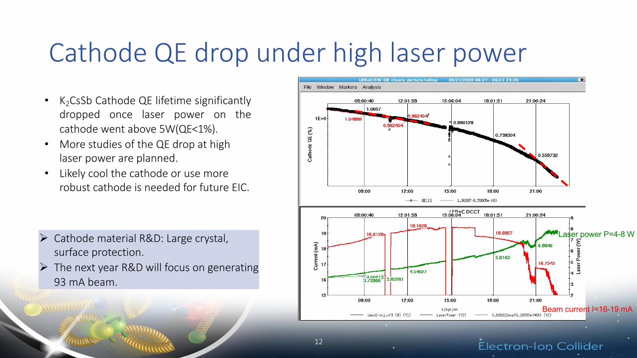
• K2CsSb Cathode QE lifetime significantlydropped once laser power on thecathode went above 5W(QE<1%).
• More studies of the QE drop at highlaser power are planned.
• Likely cool the cathode or use morerobust cathode is needed for future EIC.
Ø Cathode material R&D: Large crystal,surface protection.
Ø The next year R&D will focus on generating 93 mA beam.
Beam current I=16-19 mA
Laser power P=4-8 W

SBU polarized gun R&DEIC Achieved in stable
operation
Bunch charge [nC] 7 7.5
Peak current [A] 3.8 4.8 (No SCL)
Frequency [Hz](Bunch train #)
1(8) 1 (8000)
Voltage [kV] 300 300
Average Current 56 nA 40 uA
Polarization [%] > 85% Bulk (~35%)*
** Measure GaAs polarization at retarding field Mott polarimetry. Our gun beam line doesn’t have Mott polarimeter.
We choose inverted HVDC gun ,incorporate following new features:• Actively cool the cathode using Fluorinert.• Large cathode with large cathode plug mass and
good thermal conductivity.• Developed low storage energy HV cable.• X,Y,Z movable, electrically insulated biasable anode.

HVDC gun design
14
Inverted gun
Ball diameter 20 cm
Chamber diameter 80 cm
Gap distance (lg) 5.7 cm
Voltage 350 kV
Cathode size (lc) 1.3 cm
Electrodes angle (α) 22 degs
Cathode gradients 4.0 MV/m
Maximum gradient <10 MV/m
Anode diameter (la) 2.2 cm
Peak current 4.8 A
Bunch charge 7 nC
N_emittance 3.6 mm-mrad
Pumping speed 35000 L/s
Anode bias 3000 V
DC gap Triple-pointshed

HV electrodes treatment and installation
11/8/21 15
Corn cob polish at JLab HPR at BNL SRF Installation at SBU
AlignmentFinal assembled

Beam-line vacuum in experimentGun Vacuum3BG gauge
Beamline
Beam dump
11/8/21 16
ULVAC gauge Beam dump
Baseline 3-4 e-12
3 uA 3e-10
72 uA 1e-9
ULVAC gauge Beam Line
Baseline 3-4 e-12
3 uA 5e-12
72 uA 1.5-3 e-11
3BG gauge Gun
Baseline 5-8 e-12
3uA Low (c.c)
72 uA 2e-11,Low (c.c)
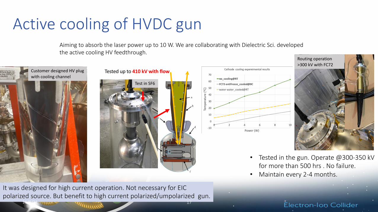
Active cooling of HVDC gunAiming to absorb the laser power up to 10 W. We are collaborating with Dielectric Sci. developedthe active cooling HV feedthrough.
Tested up to 410 kV with flow
Test in SF6
It was designed for high current operation. Not necessary for EICpolarized source. But benefit to high current polarized/umpolarized gun.
11/8/21 17
Customer designed HV plug with cooling channel
• Tested in the gun. Operate @300-350 kV for more than 500 hrs . No failure.
• Maintain every 2-4 months.
Routing operation >300 kV with FC72

Power supply and HV cable
• 400 kV Power supply is SF6free set up.
• Resistors for gun conditioningand no resistor for beamoperation.
• Custom designedSemiconductor jacket toreduce reduce the stored energy in the cable itself.
11/8/21 18
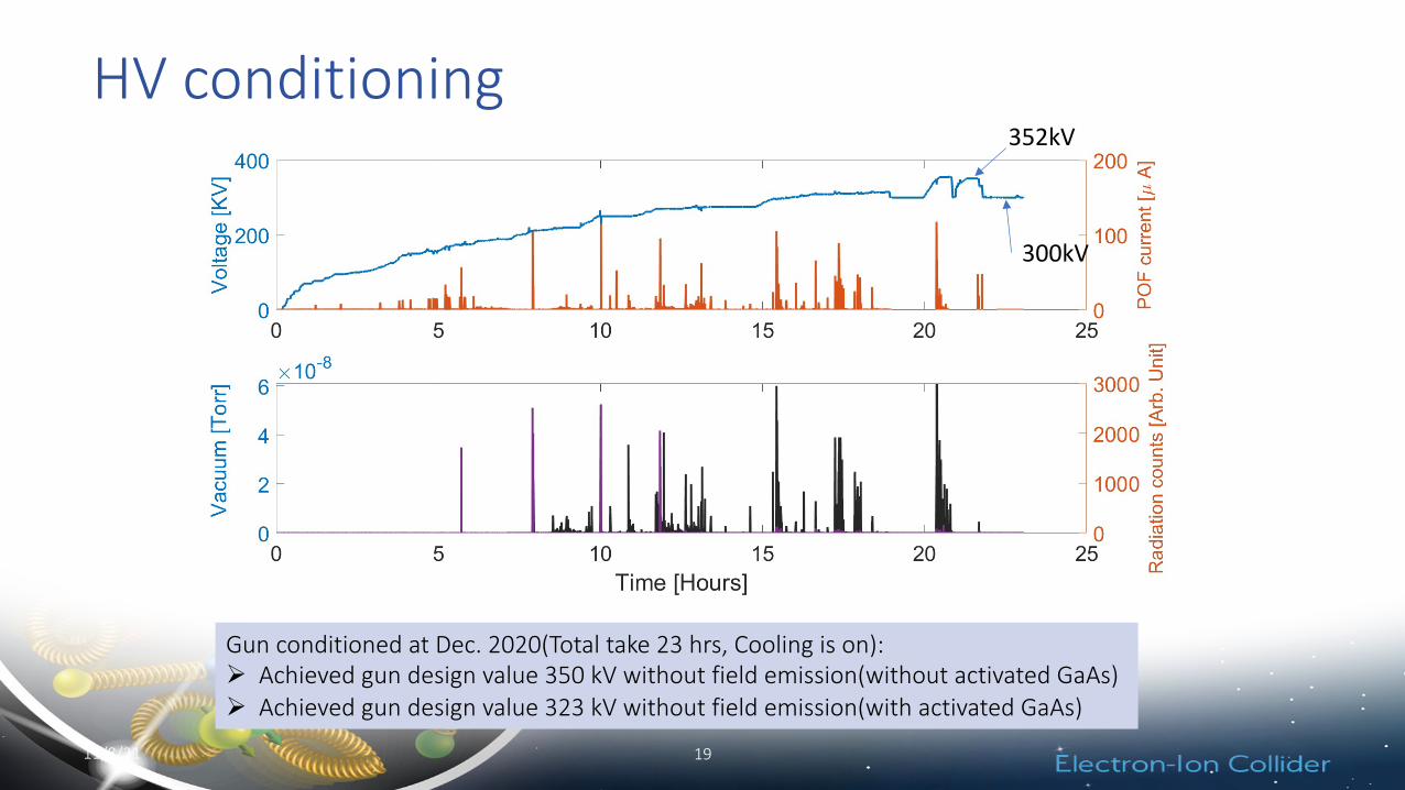
HV conditioning
Gun conditioned at Dec. 2020(Total take 23 hrs, Cooling is on):Ø Achieved gun design value 350 kV without field emission(without activated GaAs)Ø Achieved gun design value 323 kV without field emission(with activated GaAs)
11/8/21 19
352kV
300kV

Bunch charge and GaAs Lifetime using 780 nm laser
• Using 7.5 nC bunch charge polarized beam, 400 pulses/s; • We didn’t observe any QE drop in 16 hrs.• QE~1%
• Using 7.5 nC bunch charge polarized beam, 5000 pulses/s; • With anode bias(orange), we didn’t observe QE drop.• Without anode bias(green), 1/e lifetime is 102 hrs.
Dominated by the outgassing from FC.
1 nC 8 nC
� ��� ��� ��� ��� ���� ���� ����
�
�
��
��
����� ����� ������ [��]
������
[��]
7.5
5
2.5
0
pk c
urre
nt [A
]
SCL start from 12 C
EIC requirements 7 nC
Testing 9000 pulses on going, limited by laser
Beam image before the dump

Summary
21
• CeC SRF gun(up to 120 uA) and LEReC HVDC gun (up to 30 mA) are in operation, generating beam for cooling experiment. Both guns show ~weeks operation lifetime.
• Cathode QE degradations mechanisms in high current operation are being studied. More high current experiment are is planned for next year.
• We developed an inverted large cathode HVDC polarized gun. It is operated at 300 kV and ~10 nC bunch charge stablely.
• This R&D gun has cathode cooling, low storage energy cable and x,y,z moveable electric insulated anode.
• We have tested up to 64 uA average current of polarized beam. No observable QE decay with anode voltage on.

22
Thanks for your attention!Questions
Acknowledge:M. Gaowei, O. Rahman, A. Fedotov. X. Gu, P. Inacker, Y. Jing, D. Kayran, V. Litvinenko, CJ. Liaw, M. Paniccia, I. Pinayev, I. Petrushina, T. Rao, J. Skaritka, W. Liu, J. Biswas, Z. Zhao
and Jlab, Cornell and StonyBrook University colleagues!

Back up
23

Summary of 2018-2019 cathode production
24
• 28 cathodes total in 2018• 38 cathodes total in 2019
Run 2018
Run 2019 (to May)
# of cathodes 28 38
RMS Deposition QE (%) 5.41 6.28SDEV of QE (%) 0.97 0.85
10
0.87%
0.12

High intensity electron sources
25
• Quarter-wave SRF photo-electron gun• 4 K operating temperature• Bi-alkali antimonide cathodes with QE up to 11 %,• CW operation at 80 kHz with little QE drop for
months• Bunch charge up to 10.7 nC charge per bunch• Record low normalized emittance of 0.32 mm mrad
at 0.5 nC• High current operation limited by FPC

Beam Emittances from the gun
26
0 200 400 600 800 1000 1200Charge (pC)
0.0
0.5
1.0
1.5
2.0
2.5
3.0
3.5
4.0
Nor
mal
ized
RM
Sem
itta
nce
(mm
-mra
d)
"x@ YAG1 with LEBT1
"y@ YAG1 with LEBT1
"x@ YAG2 with LEBT3
"y@ YAG2 with LEBT3
"min@ YAG1 with LEBT1 by Kentaro
"min@ YAG2 with LEBT3 by Kentaro
"min@ YAG1 with Gun Sol by Kentaro
Cornell
600 ps laser pulse

Cathode performance in the gun w. multipacting
27
• Multipacting is the main reason that degrades the high QE cathode.
1. Mask the cathode edge2. Cover all the view-ports on the gun to make sure no
ambient light could leak into the gun. 3. Move the main coupler to strong coupling position and off
set the center frequency to break the multipacting resonance.
4. Use pulse mode to boost gun voltage to desired range.
Multipacting happen
In gun
In transfer system

28
Cavity Turn On Attempt with Strong MP
• Lengthen period between attempts from ~ 20 min to ~ 40 min => 5th attempt = successful turn on.
• Cathode QE not impacted by turn on attempts as MP related vacuum activity is kept minimal.
• Four repeated attempts to turn on result in getting stuck at 22 kV MP barrier.
• Attempts last only 20ms, controlled by LLRF MP trap code.• Prevents significant energy deposition => vacuum activity which
would kill cathode QE.
1 kV turn on (2.3 kV MP level just above) to allow PLL to lock on to cavity resonance.
Failure to achieve voltage in 20 msresults in turn off of drive.
Successful jump through 22 kV MP barrier.
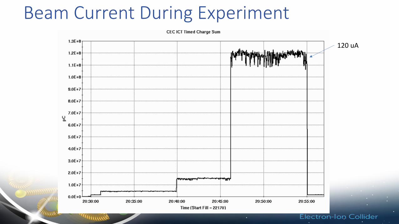
Beam Current During Experiment120 uA


