Propagation of visible and near-infrared lightthrough highly diffusing media such as biological tis-sues is a field of optics of relevant interest.1 Nowa-days many research groups study methods to performimaging of organs of the human body in order todetect small inhomogeneities or morphologicalchanges that represent possible diseases.2–5 Lightprovides a unique noninvasive probe with a poten-tially large number of applications in monitoring thehealth status of the tissue investigated by measuringits optical properties. A typical example is the bloodoxygenation survey obtained by monitoring its ab-sorption. Medical application of near-infrared lightcan take advantage of the availability of a flexible andreliable model to describe photon migration. Themain goal of this paper, to deal with light transportthrough a highly diffusing slab, is to present a com-plete set of formulas together with a discussion of thesimplifying assumptions necessary to obtain them.The slab geometry is an extensively used model of a
The authors are with the Dipartimento di Fisica dell’Universita’degli Studi di Firenze, Via Santa Marta 3, 50139 Firenze, Italy.
Received 15 April 1996; revised manuscript received 14 Febru-ary 1997.
compressed breast, as it occurs during mammogra-phy, in medical application. The formulas pre-sented are derived from the diffusion approximation~DA! of the radiative transfer equation ~RTE!, whichis one of the best known and widely used analyticalmodels that describe light diffusion through highlyturbid media.
Many hundreds of papers concerning DA have beenpublished in journals and conference proceedingsduring recent years. In particular, after the funda-mental contribution of Patterson et al.6 in which theyderived a set of formulas for the slab geometry byusing the zero boundary condition, many papers havebeen written in which different geometry7 and moreaccurate boundary conditions ~partial current bound-ary condition, extrapolated boundary condition! havebeen used to study the case of a semi-infinite medi-um.8,9 For the semi-infinite medium small differ-ences in the shape of the time-resolved reflectancewere observed when different boundary conditionswere used. Therefore many research groups use forthe fitting procedures necessary to obtain the opticalproperties from measurements of reflectance10 ortransmittance2,11 solutions of the DA that are notable to take into account reflections caused by a re-fractive index mismatch. In this paper an analysisof the previously mentioned effects is given with ref-erence to the slab geometry. The diffusion equation~DE! was solved with the extrapolated boundary con-
1 July 1997 y Vol. 36, No. 19 y APPLIED OPTICS 4587
dition. The cases of both a time-dependent and a cwsource were considered.
The formulas obtained showed that the refractiveindex mismatch can significantly affect photon migra-tion. In Ref. 12 it was shown that significant errorscan be made in determining the optical properties ofdiffusing media from measurements of diffuse trans-mittance if the effect of the refractive index mismatchis not properly taken into account: The transportcoefficient ms9 may be overestimated by approxi-mately 10–20% in typical conditions for measure-ments on a compressed breast, whereas theabsorption coefficient ma may be underestimated byabout 0.001 mm21. The errors are significantlysmaller when measurements of diffuse reflectanceare used.
The dependence of the diffusion coefficient on theabsorption coefficient ma was also investigated. TheDE is usually derived from a procedure leading to ama-dependent diffusion coefficient D 5 1y3~ms9 1 ma!.In our derivation first we obtained the time-dependent DE for a nonabsorbing medium and suc-cessively we postulated the same dependence on maexpected from the RTE. This procedure led us todefine the diffusion coefficient independent of ma:D 5 1y3ms9. The differences in assuming D or D inthe solutions of the DE become significant for largevalues ma. Comparisons with solutions of the RTEobtained by Monte Carlo ~MC! simulations showedthat a better agreement is obtained when D is used.The use of D also leads to slightly simpler inversionprocedures when measurements of diffuse reflectanceor transmittance are used to determine the opticalproperties of the diffusing medium.
2. Properties of the Radiative Transfer Equation
The RTE13,14 is the expression of the balance of en-ergy inside a volume element of the scattering me-dium. In our model only elastic scattering isconsidered: The scattering event changes the direc-tion of the photon but does not change its frequency.The absorbed energy is completely lost ~for example,it can be exchanged into heat!. This equation de-scribes the behavior of the specific intensity I~r, t, s!,i.e., the energy, moving in the direction s, per unit ofsolid angle, per unit of time, and per unit of areanormal to the s direction. The RTE can be obtainedby considering the total space and time variation ofthe specific intensity along a direction s in an elemen-tary volume and making this equal to the variation ofspecific intensity due to scattering and absorptioninside the medium. The final equation for the time-dependent case is15:
1v
]
]tI~r, t, s! 1 s z ¹I~r, t, s! 5 2mtI~r, t, s!
1mt
4p *4p
p~s, s9!I~r, t, s9!dv9 1 ε~r, t, s!, (1)
where v is the speed of light inside the diffusing me-dium, mt 5 ms 1 ma is the extinction coefficient with ms
4588 APPLIED OPTICS y Vol. 36, No. 19 y 1 July 1997
and ma as the scattering and the absorption coeffi-cients, respectively ~the inverse of ms and ma repre-sents the mean path followed by photons between twosubsequent scattering events and the mean path fol-lowed before absorption, respectively!, ε~r, t, s! is thesource term, and p~s, s9! is the scattering functionthat defines the probability for a photon moving inthe direction s to be scattered into direction s9. Thefollowing normalization was assumed for p~s, s9!:
*4p
p~s, s9!ds9 54pms
mt. (2)
If the source term is assumed to be a Dirac deltafunction, the solution represents the Green’s functionof the problem @temporal point-spread function~TPSF!# from which the solution for a generic sourcecan be obtained with convolution integrals. Thesource term of unitary strength is thus representedby
ε~r, t, s! 5 d~r!d~s!d~t!. (3)
Note two important properties of the RTE:
~1! If I~r, t, s! is a solution of Eq. ~1! with thesource term given by Eq. ~3! for a diffusing mediumcharacterized by mt and p~s, s9!, then
I#~r# , t#, s! 5 Sm# t
mtD3
I~r, t, s!, (4)
with
r# 5 rmt
m# t, t# 5 t
mt
m# t, (5)
is a solution for a diffusing medium with the extinc-tion coefficient m# t and the same scattering functionp~s, s9! and the same single-scattering albedo w0 5msymt. This property can be demonstrated with theobservation that the introduction in the RTE of thedimensionless variables mtr and mtvt yields an equa-tion independent of mt. This property, also known asthe similarity principle,16 is useful since it enablesone simply to use the results obtained in a particulargeometry for any scaled similar geometry, providingthat w0 and p~s, s9! are kept unchanged. On thebasis of this principle it is also possible to transfer thestudy of radiation transfer problems from the actualscale, in which it is often difficult to carry out exper-iments, to a more convenient scale for laboratory ex-periments.
~2! If I~r, t, s!uma50 is the solution to Eq. ~1! for anonabsorbing medium with the source term de-scribed by a Dirac delta function, then
I~r, t, s! 5 exp~2mavt!I~r, t, s!uma50 (6)
is the solution to the same equation when the absorp-tion coefficient ~independent of r! is ma. This prop-erty makes it possible to reduce the study of radiation
transfer problems in which ma is independent of r inthe case of a nonabsorbing medium and to generalizethe solution simply with Eq. ~6!.
3. Diffusion Equation for an Isotropic Point Source inan Infinitely Extended Medium
The RTE is a complicated equation and it is almostimpossible to obtain analytical solutions with a de-gree of generality that can be useful for solving realproblems. Therefore numerical methods or analyt-ical approximations are often used. The analyticalmodel widely used to describe photon migrationthrough highly diffusing media is the DA. In thisresearch we use the DA to obtain the Green’s functionfor the nonabsorbing medium, and thus we make useof the property of the RTE that concerns the depen-dence on the absorption coefficient: the Green’sfunction for ma 5 0 is generalized to the homogeneousabsorbing medium with Eq. ~6!, i.e., we postulate thesame dependence on ma expected from the RTE.
To derive the DE we refer to an isotropic sourcethat emits a pulse of unit energy Q~r, t! 5 1y4p d~r 2r*!d~t!. We obtained the DE after making the follow-ing simplifying assumptions:
~1! The specific intensity is assumed to be almostisotropic and is approximated with the first two termsof a Taylor’s expansion in terms of the power of sf z s~Ref. 13!:
I~r, t, s! 5 Ud~r, t! 13
4pFd~r, t! z s, (7)
where
Ud~r, t! 51
4p *4p
I~r, t, s!dv (8)
is the average diffuse intensity and
Fd~r, t! 5 *4p
I~r, t, s!sdv 5 Fd~r, t!sf (9)
is the diffuse flux vector;
~2! The phase function p~s, s9! is assumed to de-pend only on the scalar product s z s9;
~3! The time variation of the diffuse flux vectorover a length of 1yms9 is assumed to be negligible withrespect to the vector itself:
U 1vms9
]Fd~r, t!]t U,,uFd~r, t!u. (10)
With these simplifying assumptions and by inte-grating over all solid angles the RTE multiplied by sand the RTE, we obtain both the Fick’s law,
Fd~r, t! 5 24pD¹Ud~r, t!, (11)
and the DE for a homogeneous nonabsorbing me-dium,
S1v
]
]t2 D¹2DUd~r, t! 5 Q~r, t!, (12)
after few mathematical manipulations describedfully in Refs. 13 and 15. In Eq. ~12!, Q~r, t! is theisotropic source term and D is the diffusion coefficient,
D 51
3ms~1 2 g!5
13ms9
, (13)
with
g 5 ^cos~u!& 5
*4p
~s z s9!p~s z s9!ds9
*4p
p~s z s9!ds9
(14)
the asymmetry factor of the scattering function ~u isthe angle between s and s9!.
The general solution of Eq. ~12! for an isotropicsource that emits a pulse of unit energy in an infi-nitely extended homogeneous nonabsorbing mediumis given by14:
Ud~r, t! 5
v expS2ur 2 r*u2
4Dvt D4p~4pDvt!3y2 . (15)
The solution is thus extended to the case of a homo-geneous scattering and absorbing medium with Eq.~6!, i.e., by multiplying by exp~2mavt!:
Ud~r, t! 5
v expS2ur 2 r*u2
4Dvt2 mavtD
4p~4pDvt!3y2 . (16)
Equation ~16! conforms to a scaling property similarto the one mentioned for the RTE in Section 2, thesimilarity principle: if Ud~r, t! is the solution for adiffusing medium characterized by ms9 and ma, then
U# d~r# , t#! 5 Sm# s9
ms9D3
Ud~r, t! (17)
with
r# 5 rms9
m# s9and t# 5 t
ms9
m# s(18)
is the solution for a diffusing medium with the trans-port coefficient m# s9 and the absorption coefficient m# a,provided that m# ayma 5 m# s9yms9. Furthermore, thepostulated dependence on ma also keeps to the ab-sorption coefficient the actual physical meaning.
The procedure we used to obtain Eq. ~16! leads usto obtain the diffusion coefficient D independent of ma.The DE is usually derived directly from the RTE foran absorbing medium ~see, for example, Refs. 6, 7, 9,
1 July 1997 y Vol. 36, No. 19 y APPLIED OPTICS 4589
13!, which leads to a ma-dependent diffusion coeffi-cient:
D 51
3~ms9 1 ma!. (19)
The diffusion coefficient independent of ma was firstconsidered by Furutsu15 and Furutsu and Yamada.17
They showed that this is also definitively the case fora nonhomogeneous medium. However, many re-searchers use the ma-dependent diffusion coefficientand, as noted by Kumar et al.,18 this point is atpresent a topic of study. Also Kolinko et al.19 de-rived a diffusion coefficient independent of ma whenthey studied multiple light scattering with a proba-bilistic model. The differences between the resultsobtained when either D or D is used are significantonly for large values of ma. In Section 7 the resultsof a comparison with the solutions of the RTE ob-tained by MC simulations will be reported. Thecomparison showed that for large values of ma thebetter agreement is obtained when the diffusion co-efficient independent of ma is assumed.
4. Boundary Conditions
For a diffusing medium bounded by a convex surfaceS, the exact boundary condition for the diffuse specificintensity I~r, t, s! when there is no mismatch betweenthe refractive index of the diffusing and of the sur-rounding medium is that at the surface there shouldbe no diffuse light entering the medium13:
I~r, t, s! 5 0, (20)
for s pointed inward and for r on S.However, with the simple angular distribution as-
sumed for I~r, t, s! @Eq. ~7!# the condition described byEq. ~20! cannot be satisfied exactly and some approx-imate conditions must be considered. One of theseapproximations is the condition that, at the surface,the total diffuse flux inwardly directed should beequal to zero13:
*szq.0
I~r, t, s!~s z q!dv 5 0, (21)
for r on S, and where q is the normal to the boundarysurface S inwardly directed.
This condition is no longer valid when a refractiveindex mismatch occurs. In this case the total diffuseflux at the boundary directed into the medium is the
4590 APPLIED OPTICS y Vol. 36, No. 19 y 1 July 1997
part of the outwardly directed flux reflected by thesurface, and the following relation holds20:
*szq.0
I~r, t, s!~s z q!dv 5 *szq,0
R~s!I~r, t, s!us z qudv,
(22)
for r on S, and where R~s! is the Fresnel reflectioncoefficient for unpolarized light:
R~s! 512 HFn cos~ui! 2 cos~ut!
n cos~ui! 1 cos~ut!G2
1 Fcos~ui! 2 n cos~ut!
cos~ui! 1 n cos~ut!G2J . (23)
In Eq. ~23! n 5 n2yn1 represents the relative re-fractive index, i.e., the ratio between the refractiveindex of the diffusing medium and that of the ex-ternal medium; ui is the angle of incidence of theradiation @cos~ui! 5 2s z q#; and ut 5 arcsin@n sin~ui!#is the refracted angle. We note that for n 5 1.4—atypical value for the tissue–air interface—Eq. ~22!results in more than 50% of the photons being re-flected if an isotropic distribution for I~r, t, s! isassumed. Therefore the effect of reflections pro-vokes a redistribution of light into the turbid slaband significant effects should be expected. Thecondition given by Eq. ~22! can be expressed interms of the average diffuse intensity. By solvingEq. ~22! with the diffuse specific intensity given byEq. ~7!, we obtain
Ud~r, t! 1A2p
Fd~r, t! z q 5 0, (24)
for r on S, and where the coefficient A is given by
A 5
1 1 3 *0
py2
R~ui!cos2~ui!sin~ui!dui
1 2 2 *0
py2
R~ui!cos~ui!sin~ui!dui
. (25)
From Eqs. ~11! and ~24! we obtain the followingboundary condition ~partial current boundary condi-tion!9,19:
Ud~r, t! 2 2ADq z ¹Ud~r, t! 5 0, (26)
for r on S.The integrals in Eq. ~25! were calculated with the
software MATHEMATICA and the following equationswere obtained for n , 1:
~1 1 6n4 1 n8!logS21 1 n1 1 n D 1 4~n2 1 n6!logFn2~1 1 n!
n 2 1 G~n2 2 1!2~n2 1 1!3 . (30)
More details about these expressions, together with apolynomial fit that can be used to approximate thecoefficient A, are given in Appendix A.
To solve the DE, two additional simple but moreapproximate boundary conditions are commonly usedinstead of the partial current boundary condition:the zero boundary condition and the extrapolatedboundary condition. The zero boundary condition—the most simple and approximate—assumes the av-
erage diffuse intensity equal to zero at the physicalboundary.6 With this approximation it is impossible
to take into account the effect of reflection at the
boundary. The extrapolated boundary condition as-sumes equal to zero the average diffuse intensity atan extrapolated boundary outside the turbid mediumat a distance ze given by8,9:
ze 5 2AD. (31)
This condition is an approximation of Eq. ~26!, as-suming a linear behavior of the average diffuse in-tensity around the geometrical boundaries.21
1 July 1997 y Vol. 36, No. 19 y APPLIED OPTICS 4591
5. Solution of the Diffusion Equation for a DiffusingSlab
In this section solutions of the time-dependent DEfor a diffusing slab are presented. A scheme of thegeometry together with a description of some of thenotations used is shown in Fig. 1. From these so-lutions the solutions for a semi-infinite diffusingmedium can be obtained. In our scheme a narrowcollimated pulsed light beam is normally incidentupon the surface of a diffusing slab; the pulse issupposed to be mathematically described by a Diracdelta function ~centered at the time t 5 0!, and it issupposed to be thin and collimated ~pencil beam!.The coordinate system has been chosen with theorigin at the point in which light is entering themedium with the z axis along the direction of prop-agation of the collimated pulse. This situation is agood approximation of the real case in which anultrashort laser pulse, its dimension negligible withrespect to the other geometrical dimensions in-volved in the problem, is used. However, the DEwas obtained with reference to an isotropic sourceand Eqs. ~12! and ~16! cannot be used for the highdirectional beam.
Various methods have been used to model thepencil beam in the DE: The monodirectionalsource was modeled by Ishimaru13 and Keijzer etal.20 with a distribution of sources located at thepoints at which the first scattering event occurs,with the intensity proportional to ms exp~2zmt!, andwith the angular distribution given by the scatter-ing function. Groenhuis et al.22 used a similarmodel but assumed a scattering function equal tothe sum of an isotropic term and of a strongly for-ward peaked term, leading to a line distribution ofisotropic sources with strengths proportional toexp@2z~ms9 1 ma!#. By using this model for thesource and the partial current boundary condition,Groenhuis et al.22 obtained a formula for the diffuse
Fig. 1. Slab geometry and some notations.
4592 APPLIED OPTICS y Vol. 36, No. 19 y 1 July 1997
reflectance for the slab in the time-independentcase. A further approximation is often made ~lead-ing to simpler solutions!, assuming that all incidentphotons are initially scattered ~isotropically! at adepth z0 5 1yms9 below the surface: the line ofsources is thus replaced with a single isotropicsource located at z 5 z0 into the medium.6,7,9 Forthe reflectance from the semi-infinite medium inthe time-independent case, Farrel et al.23 showedthat the solutions obtained, assuming the singleisotropic source and the line of isotropic sources, arealmost indistinguishable for distances from thepencil beam larger than z0.
The solutions reported in this section were ob-tained with the simplest approximation assumed;they refer to an isotropic point source of unitarystrength: Q~r, t! 5 ~1y4p!d~x!d~y!d~z 2 z0!d~t! atz 5 z0. To solve the DE we assumed the extrapo-lated boundary condition; i.e., the average diffuseintensity has been assumed equal to zero at twoextrapolated flat surfaces outside the turbid me-dium at a distance ze 5 2AD from the physicalboundaries of the slab. This condition can beachieved with not just one isotropic point sourceinside the slab but with an infinite number of di-poles in an infinite diffusing medium, having thesame optical properties and representing pairs ofpositive and negative sources ~see Fig. 2!.6,7 Thepositive and negative sources are placed at
Hz1,m 5 2m~s 1 2ze! 1 z0
z2,m 5 2m~s 1 2ze! 2 2ze 2 z0
for positive sourcesfor negative sources
,
m 5 ~0, 61, 62, . . . !. (32)
According to this scheme, the average diffuse inten-sity can be split into two parts, one due to the positivesources and the other due to the negative ones. Byusing Eq. ~16! to obtain the contribution of everypositive source and adding these contributions, weobtain Ud1~r, t!. An analogous procedure gives thecontribution Ud2~r, t! of the negative sources. Thefinal expression for the average diffuse intensity at a
Fig. 2. Positions of source dipoles.
distance r from the z axis is
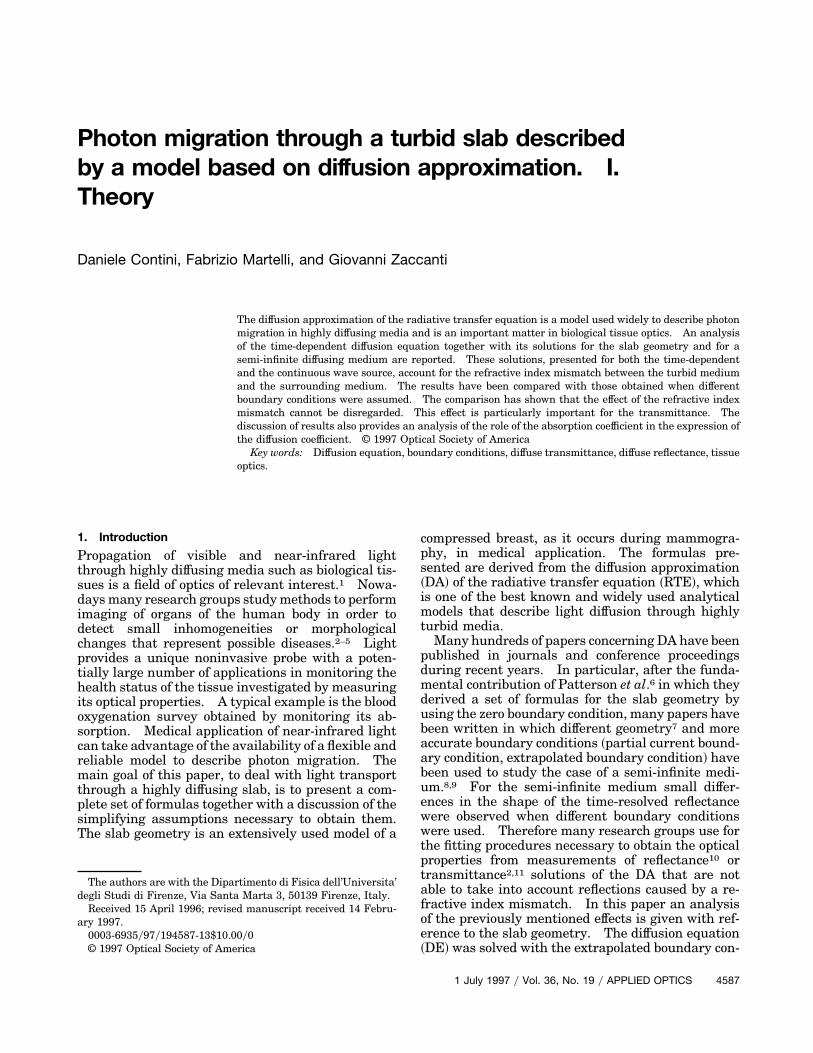
5Ud~z, r, t! 5 Ud1~z, r, t! 1 Ud2~z, r, t!,
Ud1~z, r, t! 5
v expS2mavt 2r2
4DvtD4p~4pDvt!3y2 (
m52`
m51`
expF2~z 2 z1,m!2
4Dvt G ,
Ud2~z, r, t! 5 2
v expS2mavt 2r2
4DvtD4p~4pDvt!3y2 (
m52`
m51`
expF2~z 2 z2,m!2
4Dvt G .
(33)
The time-resolved reflectance R~r, t!, i.e., the powercrossing the surface at z 5 0, per unit area, at adistance r from the z axis ~with any exit angle!, can beevaluated as9:
R~r, t! 5 *szq,0
@1 2 R~s!#I~r, z 5 0, t, s!~2q z s!dv,
(34)
with R~s! as the Fresnel reflection coefficient. Sub-stituting Eq. ~7! into Eq. ~34! and taking into accountEqs. ~24! and ~26!, we can demonstrate that aftersome calculation
R~r, t! 5 2q z Fd~r, z 5 0, t! 5 4pD]
]zUd~r, z 5 0, t!.
(35)
The procedure used to obtain Eq. ~35! does not involveany further approximation apart from that necessaryto derive the DE. Therefore in contrast to what hasbeen reported in Ref. 9, there is no conflict betweenEq. ~34! used in Ref. 9 and Eq. ~35!, which is usuallyused to evaluate the reflectance for the semi-infinitemedium.6,8
With a similar procedure it is possible to evaluate the
time resolved transmittance T~r, t!:
T~r, t! 5 2q z Fd~r, z 5 s, t! 5 24pD]
]zUd~r, z 5 s, t!,
(38)
~with q inwardly directed! from which
T~r, t! 5
expS2mavt 2r2
4DvtD2~4pDv!3y2t5y2 (
m52`
1` Fz1,m expS2z1,m
2
4DvtD2 z2,m expS2
z2,m2
4DvtDG . (39)
The functions R~r, t! and T~r, t! also represent theprobability that a photon, entering the medium at theorigin of the coordinate system at t 5 0, exits at time tand at distance r from the z axis per unit of time andunit of area. By using the uniqueness theorem for theheat conduction equation, Martelli12 demonstratedthat Eqs. ~36! and ~39! are the only possible solutionswhen the extrapolated boundary condition is assumed.
Equations ~36! and ~39! are infinite series andshould be truncated for practical applications. Sincethe distance from the boundaries @on which R~r, t! andT~r, t! are evaluated# of the sources that correspond tothe index m increases when m increases, the contribu-tion of sources that correspond to high values of m isexpected to be significant only for large values of randyor t. As an example, if we refer to the time in-terval on which the values of R~r, t! and T~r, t! remainwithin 3 orders of magnitude with respect to the max-imum, 7 dipoles ~m 5 0, 61, 62, 63! are sufficient tomaintain the truncation error within 0.1% for a slabwith s 5 40 mm, ms9 5 0.5 mm21, ma 5 0, and n 5 1.4when r , s. The error decreases when ma, s, or ms9 isincreased. ~We note that accurate time-resolvedmeasurements are difficult to obtain over a dynamicrange greater than 2–3 orders of magnitude!.
By integrating Eqs. ~36! and ~39! over the entireexit surface we obtain the total time-resolved diffuse
1 July 1997 y Vol. 36, No. 19 y APPLIED OPTICS 4593
reflectance R~t! and transmittance T~t!:
R~t! 5 *0
1`
R~r, t!2prdr 5 2exp~2mavt!
2~4pDv!1y2t3y2
3 (m52`
1` Fz3,m expS2z3,m
2
4DvtD 2 z4,m expS2z4,m
2
4DvtDG ,
(40)
T~t! 5 *0
1`
T~r, t!2prdr 5exp~2mavt!
2~4pDv!1y2t3y2
3 (m52`
1` Fz1,m expS2z1,m
2
4DvtD 2 z2,m expS2z2,m
2
4DvtDG .
(41)R~t! and T~t! also describe the time-resolved reflec-tance and transmittance when an infinitely widebeam, having constant radiance, impinges perpendic-ularly on the surface of the slab. For maintainingthe truncation error within 1%, five dipoles should beretained in Eqs. ~40! and ~41! when the conditionspreviously assumed for R~r, t! and T~r, t! are consid-ered.
The relationships for the cw source @Eqs. ~45!–~50!#can be obtained by integrating the time-resolved re-sponses. The time integrals have been performed,taking into account that for Re~B! . 0 and Re~g! .0,24
*0
1`
tv21 expS2Bt
2 gtDdt 5 2SBgD
vy2
Kv@2~gB!1y2#, (42)
where Kv~x! are the modified spherical Bessel func-tions of the third kind for which
Kv11y2~x! 5 K2v21y2~x! ~v 5 0, 1, 2, . . . !, (43)and using the analytical form of the K functions,
5Sp
2xD1y2
K1y2~x! 5p
2xexp~2x!
Sp
2xD1y2
K3y2~x! 5p
2x~1 1 x21!exp~2x!.
(44)
The analytical expression for the time integrals canbe obtained only for absorbing media ~ma . 0!. Byintegrating Eqs. ~36! and ~39! we obtain
R~r! 5 21
4p (m52`
1` Sz3,m~r2 1 z3,m2!23y2
3 H1 1 Fma~r2 1 z3,m
2!
D G1y2J3 expH2 Fma~r
2 1 z3,m2!
D G1y2J2 z4,m~r2 1 z4,m
2!23y2 3 H1 1 Fma~r2 1 z4,m
2!
D G1y2J3 expH2 Fma~r
2 1 z4,m2!
D G1y2JD , (45)
4594 APPLIED OPTICS y Vol. 36, No. 19 y 1 July 1997
T~r! 51
4p (m52`
1` Sz1,m~r2 1 z1,m2!23y2
3 H1 1 Fma~r2 1 z1,m
2!
D G1y2J3 expH2 Fma~r
2 1 z1,m2!
D G1y2J 2 z2,m
3 ~r2 1 z2,m2!23y2 3 H1 1 Fma~r
2 1 z2,m2!
D G1y2J3 expH2 Fma~r
2 1 z2,m2!
D G1y2JD . (46)
The quantity R~r!dS~T~r!dS! represents the probabil-ity that a photon emitted by the source exits from thesurface element dS at z 5 0 ~z 5 s! at distance rregardless of the length of its trajectory. We ob-tained Eqs. ~45! and ~46! assuming ma . 0. How-ever, they give correct values even when ma 5 0. Fora diffusing slab with s 5 40 mm with ms9 5 0.5 mm21,ma 5 0, and n 5 1.4, it is necessary to retain fivedipoles for transmittance at r 5 0 and 11 dipoles forreflectance at r 5 40 mm to have a truncation errorsmaller than 1%.
From Eqs. ~36! and ~39! the mean path length fol-lowed by photons before they exit from the slab canalso be evaluated:
^l~r!&R 5
v *0
1`
tR~r, t!dt
*0
1`
R~r, t!dt
5 21
8pDR~r! (m52`
1`
3 (z3m~r2 1 z3m2!21y2 3 expH2 Fma~r
2 1 z3m2!
D G1y2J2 z4m~r2 1 z4m
2!21y2
3 expH2 Fma~r2 1 z4m
2!
D G1y2J) , (47)
^l~r!&T 5
v *0
1`
tT~r, t!dt
*0
1`
T~r, t!dt
51
8pDT~r! (m52`
1`
3 (z1m~r2 1 z1m2!21y2 3 expH2 Fma~r
2 1 z1m2!
D G1y2J2 z2m~r2 1 z2m
2!21y2
3 expH2 Fma~r2 1 z2m
2!
D G1y2J) . (48)
These equations can be used only when ma . 0. Fora diffusing slab with s 5 40 mm, ms9 5 0.5 mm21, ma5 0.005 mm21, and n 5 1.4, it is sufficient to retaintwo dipoles for the transmittance at r 5 0 and four for
the reflectance at r 5 40 mm to have a truncationerror smaller than 1%; but the number of dipolesshould be increased to about 30 when ma is decreasedto 1025 mm21.
The fraction of the incident energy reflected R andtransmitted T can be obtained by performing the timeintegral of Eqs. ~40! and ~41!:
R 5 212 (
m52`
1` Hsgn~z3,m!expF2Sma
DD1y2Uz3,mUG2 sgn~z4,m!expF2Sma
DD1y2Uz4,mUGJ , (49)
T 512 (
m52`
1` Hsgn~z1,m!expF2Sma
DD1y2Uz1,mUGJ2 sgn~z2,m!expF2Sma
DD1y2Uz2,mUG , (50)
where sgn~x! 5 21 if x , 0 and sgn~x! 5 1 if x . 0.The quantity 1 2 ~R 1 T! is the fraction of the inci-dent energy absorbed by the medium. For example,for a homogeneous slab with s 5 40 mm, ms9 5 0.5mm21, and n 5 1.4, Eqs. ~49! and ~50! give R 50.6736 and T 5 0.0046 when ma 5 0.01 mm21; there-fore 32.18% of the energy is absorbed by the medium.When the absorption coefficient approaches the limitma 5 0, the fraction of energy absorbed by the me-dium, as expected, also approaches zero. In addi-tion, Eqs. ~49! and ~50! can be used only for ma . 0.For a slab with s 5 40 mm, ms9 5 0.5 mm21, ma 51025 mm21, and n 5 1.4, it is necessary to retainapproximately 20 dipoles for reflectance and 30 fortransmittance to have a truncation error smallerthan 1%.
The approximation of a semi-infinite medium hasoften been used to describe problems that involvehighly diffusing media. The approximation is validfor slabs sufficiently thick so that the probability forthe radiation to escape from the surface opposite thesource is negligible. In this case the boundary con-ditions are fulfilled, retaining only the first of thedipole sources necessary for the slab. Therefore thereflectance for the semi-infinite medium is obtainedsimply, retaining only the term with m 5 0.
The formulas for a semi-infinite homogeneous dif-fusing medium are simpler to work with than thosefor the slab. A further simplification of the formulasfor the cw source can be assumed if ry~2ze 1 zo! .. 1:
Rsi~r! >ze 1 z0
2pr3 F1 1 rSma
DD1y2GexpF2rSma
DD1y2G , (51)
^l~r!&si >r2
2D1
1 1 r@~mayD!#1y2 . (52)
Expression ~52! shows that for a semi-infinite nonab-sorbing medium the approximated mean path lengthis simply proportional to r2. With ms9 5 1 mm21, ma5 0.01 mm21, and n 5 1, the value of Rsi~r! obtainedwith Expression ~51! differs by 2.2% at r 5 20 mm and
by 1.4% at r 5 50 mm with respect to the value givenby Eq. ~45!. Under the same conditions, the value of^l&si we obtained using Expression ~52! differs by0.46% at r 5 20 mm and by 0.09% at r 5 50 mm.
6. Comparison with Other Models
The various boundary conditions used to solve the DEfor light propagation through turbid media have beenused to study the reflectance from the semi-infinitemedium.6,8,9,20,25 There is a close agreement be-tween solutions based on the partial current bound-ary condition and the extrapolated boundarycondition, both in the time domain8,25 and in the fre-quency domain.9 In particular, Hielscher et al.25
showed that the differences for the time-resolved re-flectance are almost always less than 2% and thus forall practical conditions no improvement is gainedwhen the partial current boundary condition is used.Late times solutions based on the zero boundary con-dition and on the partial current boundary conditiondiffer essentially for an amplitude factor, dependingon the refractive index mismatch.8,25 Therefore theresults in the frequency domain also show small dif-ferences when the source–receiver distance is suffi-ciently large.9 Therefore the simplest relationshipsbased on the zero boundary condition also can be usedto invert measurements of diffuse reflectance, both inthe time domain and in the frequency domain.
For the slab geometry the solutions based on thezero boundary condition presented by Patterson etal.6 are also commonly used to determine ma and ms9from time-resolved measurements of reflectance ortransmittance carried out on compressed breast2,10
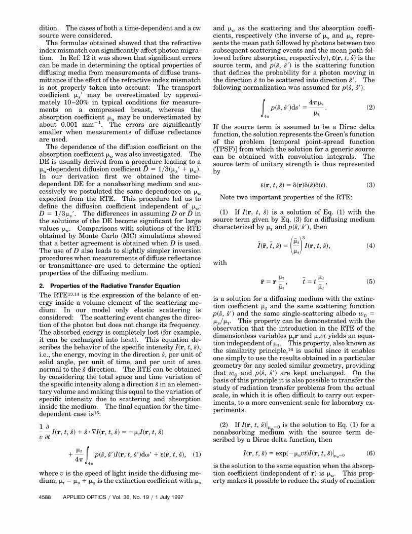
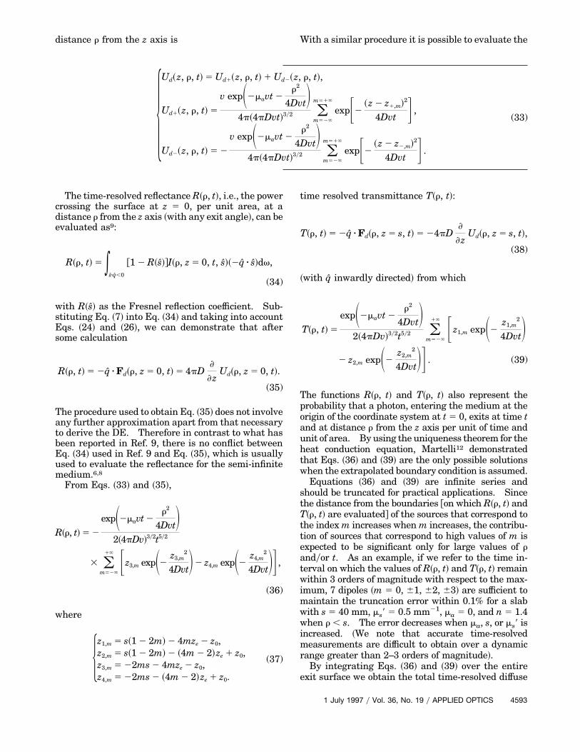
and on phantoms.11 The analytical solutions re-ported in Ref. 6 can be obtained from the equationsreported in Section 3, assuming ze 5 0. To comparethe solutions based on the extrapolated boundarycondition and on the zero boundary condition, werefer to Fig. 3. The figure refers to a nonabsorbingslab 40-mm thick with ms9 5 0.5 mm21. Two valuesfor the relative refractive index were considered:n 5 1 and n 5 1.4. Figure 3~a! reports the time-resolved transmittance at r 5 0 ~coaxial to the pencilbeam!. Both the shape and the intensity of thecurves show significant differences. In particular,the TPSF that refers to the zero boundary condition~this TPSF is independent of n! shows an intensitysignificantly lower, the maximum occurs at shortertimes, and the slope at long times is larger with re-spect to the extrapolated boundary condition. Sincethe slope at long times can be used to determine maand the position of the maximum to determine ms9,this figure shows clearly that a reliable model forinversion procedures should account for the effect ofreflections when measurements are carried out on adiffusing slab. Furthermore, the zero boundary con-dition gives a TPSF that is too approximated even inthe case n 5 1. In Ref. 12 it was shown that thevalues of ms9 may be overestimated by 10–20% andthe values of ma underestimated by '0.001 mm21
when transmittance measurements are carried out inconditions typical for a compressed breast.
1 July 1997 y Vol. 36, No. 19 y APPLIED OPTICS 4595
The comparison for the time-resolved reflectance isreported in Fig. 3~b! for r 5 40 mm. Also in this casethere are significant differences in the intensity, butsmaller differences in the shape, of the curves asobserved for the reflectance in the semi-infinite me-dium.8 Since the inversion procedures to determinema and ms9 usually work on the shape of the measuredTPSF, smaller errors are expected when solutionsbased on the zero boundary condition are used toinvert measurements of time-resolved reflectance.
The differences between the curves of Fig. 3 thatrefer to different values of n can be explained by theredistribution, due to reflection, of photons inside theslab. Reflection removes a consistent fraction ofphotons that, in the case n 5 1, would exit near thesource at short times ~with n 5 1.4 more than 50% ofphotons are reflected if an isotropic distribution forthe radiance is assumed!. These photons continueto migrate through the slab and thus the probabilityof exiting at longer distances and longer times in-creases.
In Section 4 two expressions were reported @Eq.~27! and Eq. ~29!# to evaluate the coefficient A @Eq.
Fig. 3. Comparison between the solutions of the DE on the basisof the extrapolated boundary condition ~continuous lines! for twovalues of the relative refractive index n 5 1.4 ~higher curve! andn 5 1 ~lower curve!, and the zero boundary condition ~dashedcurve!. Data refer to ~a! the time-resolved transmittance at r 5 0and ~b! the time-resolved reflectance at r 5 40 mm for a slab40-mm thick with ms9 5 0.5 mm21 and ma 5 0.
4596 APPLIED OPTICS y Vol. 36, No. 19 y 1 July 1997
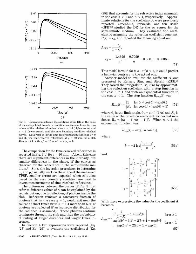
~25!# that accounts for the refractive index mismatchin the case n . 1 and n , 1, respectively. Approx-imate solutions for the coefficient A were previouslyreported. Groenhuis, Ferwerda, and ten Bosch~GFB!22 studied the DE for the cw source for thesemi-infinite medium. They evaluated the coeffi-cient A assuming the reflection coefficient constant,R~s! 5 rd, and reported the following equation:
AGFB 51 1 rd
1 2 rd,
rd 5 21.4399
n2 10.7099
n1 0.6681 1 0.0636n.
(53)
This model is valid for n $ 1; if n , 1, it would predicta behavior contrary to the actual one.
Another model to evaluate the coefficient A waspresented by Keijzer, Star, and Storchi ~KSS!.20
They solved the integrals in Eq. ~25! by approximat-ing the reflection coefficient with a step function inthe case n $ 1 and with an exponential function inthe case n , 1. The step function Rstep~s! was
where qc is the limit angle, qc 5 sin21~1yn! and R0 isthe value of the reflection coefficient for normal inci-dence, R0 5 @~n 2 1!y~n 1 1!#2. When n , 1 theexponential function was
Rexp~s! 5 exp@2b cos~q!#, (55)
where
b 5 22 logSa1 1 a2
2 D , (56a)
and
a1 5 3nS1 234
n2D1y2
212
nS1 234
n2D1y2
1124
2
,
a2 5 3n2
2 S1 234
n2D1y2
n2
1 S1 234
n2D1y242
. (56b)
With these expressions the value for the coefficient Abecomes
~The expression AKSS for the case n , 1 was notreported in Ref. 20; we calculated it by following thesuggestions given in Ref. 20.!
In Fig. 4 curves that represent the coefficient A forthe model described in this paper, for the GFB model,and for the KSS model are presented. The differencebetween the value of A given by our model and by theKSS model is less than 7% for all ranges of values ofn reported. The difference between the value of Agiven by our model and by the GFB model is less than12%. The effect of these differences on the TPSF isusually small although the differences increase atlong times. Our results show that the difference inthe TPSF obtained with these various models is usu-ally a small percentage. The main effect is to changeslightly the slope of the tail at long times.
In a recent paper Aronson26 reported an expressionfor the extrapolated distance for n . 1. The resultsobtained with Eq. ~29! are in agreement with resultsreported in Ref. 26.
Several authors6,13 suggest the possibility of a cor-rection to the boundary condition given by Eq. ~26!.This correction comes from the analytical solution ofa scattering problem known as the Milne prob-lem.13,14 The correction consists of replacing the fac-tor 2 in Eq. ~26! with a factor 2.1312. This correctionis not, however, completely justifiable when we dealwith a refractive index mismatch at the boundaries ofthe diffusing medium. We carried out some calcula-tions using this correction and the results were notsignificantly changed for n 5 1. Differences repre-sented a small percentage of change on the tail of theTPSF. When relative refractive indices differentfrom 1 are considered, the correction leads to resultsslightly different from those obtained with the condi-tion given in Eq. ~26!. We preferred to implement allour calculations using Eq. ~26!, which is completelyanalytically justifiable.
7. Dependence of the Diffusion Coefficient onAbsorption: Comparison with Monte Carlo Results
The differences in the solutions of the DE when D orD is used are generally small and become significant
Fig. 4. Comparison among the values of A obtained with differentmodels. Values obtained with Eq. ~53! ~dotted curve!, Eq. ~57!~thin continuous curve! and Eqs. ~27! and ~29! ~thick continuouscurve! are reported.
only for large values of ma. To investigate which ofthe results is more accurate, we made comparisonswith solutions of the RTE obtained by MC simula-tions. As an example, Fig. 5 depicts a comparisonfor a semi-infinite medium with ms9 5 1 mm21 andg 5 0 for both the time-resolved and the cw reflec-tance. Figure 5~a!, referring to the TPSF at r 5 30mm for ma 5 0.05 mm21, shows that an excellentagreement with the numerical results is obtainedwhen the ma-independent diffusion coefficient D isused, whereas significant discrepancies are observedwhen the ma-dependent diffusion coefficient D is used.The differences are more significant at short timesand are '30% near the maximum ~the MC resultswere reported only for t . 280 ps since, owing to thesmall number of useful photons for shorter times, thecurve was noisy!. Figure 5~b!, referring to the cwsource, depicts the percentage of difference between
Fig. 5. Comparison between the results obtained from MC sim-ulations and from the DE when D or D is used. Data refer to thereflectance from a semi-infinite medium with ms9 5 1 mm21, andn 5 1.4: ~a! TPSF at r 5 30 mm for ma 5 0.1 mm21, the dashednoisy curve refers to MC results, the thin and thick curves refer toD and D, respectively; ~b! percentage of difference between thereflectance evaluated with the DE and the MC results for the cwsource. Dashed and continuous curves refer to D and D, respec-tively. The results are reported for three values of ma: 0.01,0.05, and 0.1 mm21 ~lower to upper curve for D, upper to lowercurve for D!.
1 July 1997 y Vol. 36, No. 19 y APPLIED OPTICS 4597
the reflectance evaluated with the DE results @Eq.~45!# and with the MC results versus the distance.The results are reported for three values of ma: 0.01,0.05, and 0.1 mm21. When D is used in the DE, thedifference with respect to MC results is almost con-stant for distances r . 5 mm: it is '21% for ma 50.01 mm21, '12% for ma 5 0.05 mm21, and remainswithin 10% even when ma 5 0.1 mm21. When D isused, the differences increase significantly with boththe distance and ma: at r 5 25 mm, the reflectanceis underestimated by 80% for ma 5 0.1 mm21.
The comparison indicates that the solutions of theDE give more accurate results when the ma-independent diffusion coefficient is used. The for-mulas obtained from the DE are often used to invertmeasurements of diffuse reflectance or transmittancein order to obtain the optical properties of the diffus-ing medium. Thus more accurate results are ob-tained when the ma-independent diffusion coefficientis assumed. Also the algorithm for the inversionprocedure is in this case slightly more simple. How-ever, from a practical point of view the differences inthe values of ma and ms9 obtained when the ma-dependent diffusion coefficient is used are usuallysmall; to evaluate the discrepancy we may considerthat, after all, the inversion procedure yields the dif-fusion coefficient and the absorption coefficient. Thevalue obtained for ma is thus the same whether D orD is used in the formulas, whereas the value of ms9obtained by D results in an underestimation equal toma with respect to the value obtained by D. Theerror can be significant when measurements are car-ried out on highly absorbing media. As an example,Wilson et al.27 used the solution of the DE for a cwsource in an infinitely extended medium to determinema and ms9, using the added absorption method evenwhen ma was approximately 20% of ms9. In theseconditions an underestimation of ms9 of about 20% isexpected.
8. Discussion and Conclusions
In this paper the solutions of the DE developed todeal with light propagation through a turbid slab andthrough a semi-infinite diffusing medium are pre-sented. These solutions describe both the time-dependent and the cw source. The extrapolatedboundary condition was used to take into account therefractive index mismatch between the diffusing andthe surrounding media. The solutions were com-pared with those obtained with different boundaryconditions. Our results showed that the redistribu-tion of light inside the turbid medium owing to re-flection significantly affects photon migration,provoking appreciable changes in the TPSF. Theseeffects are particularly important for the diffusetransmittance and cannot be disregarded: with theformulas based on the zero boundary condition, inwhich the effect of reflections is not accounted for, thevalue of ms9 obtained from measurements of time-resolved transmittance results was overestimated byapproximately 10–20% in typical conditions for mea-surements on a compressed breast.
4598 APPLIED OPTICS y Vol. 36, No. 19 y 1 July 1997
The procedure we followed to obtain the DE led usto define the diffusion coefficient D 5 1y3ms9 indepen-dent of the absorption coefficient. Comparisons withMC results showed that a better agreement is ob-tained when the coefficient D is assumed instead ofthe ma-dependent coefficient D 5 1y3~ms9 1 ma! that isusually used. With the diffusion coefficient D thephysical meaning of the absorption coefficient is alsoretained and a slightly simpler algorithm for the in-version procedures follows.
In Ref. 12, comparisons among the results obtainedfrom these formulas and the results of MC simula-tions showed that the solutions of the DE presentedin this paper give an excellent description of photonmigration through the slab for a large range of opticalproperties and also take into account with good ac-curacy the effect of a refractive index mismatch.
Appendix A
Equations ~27! and ~29! for the coefficient A wereobtained, developing the integrals in Eq. ~25! with thesoftware MATHEMATICA. The cases n , 1 and n . 1are considered separately. In the n 5 1 case noreflection occurs, the Fresnel’s reflection coefficient iszero, and A 5 1. Although Eqs. ~27! and ~29! are notstrictly defined for n 5 1, it is possible to demonstrateby developing Eqs. ~27! and ~29! in series around n 51 that
limn312
A~n! 5 limn311
A~n! 5 1. (A1)
Equations ~27! and ~29! are complicated. To ob-tain simpler expressions for practical applications, apolynomial fit was performed and the following ap-proximate relationships were obtained:
Afit 5 3.084635 2 6.531194n 1 8.357854n2
2 5.082751n3 1 1.171382n4 for n # 1,(A2)
Afit 5 504.332889 2 2641.00214n 1 5923.699064n2
2 7376.355814n3 1 5507.53041n4
2 2463.357945n5 1 610.956547n6
2 64.8047n7 for n . 1. (A3)
Calculation showed that the percentage of error ~A 2Afit!yA with Eqs. ~A2! and ~A3! instead of Eqs. ~27!and ~29! is far below 0.05% for n, ranging between 0.6and 1.6.
Part of the results presented here were obtained atthe Blackett Laboratory, Imperial College of Science,Technology and Medicine in London, where D. Con-tini spent a period of seven months funded by theEuropean Community through the Human Capitaland Mobility Project ~contract ERB-CHRX-CT93-0335!. The authors thank J. C. Dainty ~ImperialCollege! for support and useful discussions. We alsothank P. Bruscaglioni for useful suggestions and dis-cussions. Part of the research was supported by
Consiglio Nazionale delle Ricerche grant95.01135.02.
References1. B. Chance and R. R. Alfano, eds., Optical Tomography, Photon
Migration, and Spectroscopy of Tissue and Model Media:Theory, Human Studies, and Instrumentation, Proc. SPIE2389 ~1995!.
2. G. Mitic, J. Kolzer, J. Otto, E. Plies, G. Solkner, and W. Zinth,“Time-gated transillumination of biological tissues and tissue-like phantoms,” Appl. Opt. 33, 6699–6710 ~1994!.
3. J. C. Hebden and D. T. Delpy, “Enhanced time-resolved imag-ing with a diffusion model of photon transport,” Opt. Lett. 19,311–313 ~1994!.
4. G. Zaccanti, D. Contini, M. Gurioli, A. Ismaelli, H. Liszka, andA. Sassaroli, “Detectability of inhomogeneities within highlydiffusing media,” in Optical Tomography, Photon Migration,and Spectroscopy of Tissue and Model Media: Theory, Hu-man Studies, and Instrumentation, B. Chance and R. R. Al-fano, eds., Proc. SPIE 2389, 755–762 ~1995!.
5. S. Fantini, M. A. Franceschini, E. Gratton, “Quantitative de-termination of the absorption-spectra of cromophores instrongly scattered media. A light-emitting-diode based tech-nique,” Appl. Opt. 33, 5204–5213 ~1994!.
6. M. Patterson, B. Chance, and B. C. Wilson, “Time resolvedreflectance and transmittance for the non-invasive measure-ment of tissue optical properties,” Appl. Opt. 28, 2331–2336~1989!.
7. S. R. Arridge, M. Cope, and D. T. Delpy, “The theoretical basisfor the determination of optical pathlengths in tissue: tem-poral and frequency analysis,” Phys. Med. Biol. 37, 1531–1560~1992!.
8. M. S. Patterson, S. J. Madsen, J. D. Moulton, and B. C. Wilson,“Diffusion equation representation of photon migration in tis-sue,” in IEEE Microwave Theory and Techniques SymposiumDigest ~IEEE, New York, 1991!, Vol. BB-1, pp. 905–908.
9. R. C. Haskell, L. O. Svaasand, T. T. Tsay, T. C. Feng, M. S.McAdams, and B. J. Tromberg, “Boundary conditions for thediffusion equation in radiative transfer,” J. Opt. Soc. Am. A 11,2727–2741 ~1994!.
10. K. Suzuki, Y. Yamashita, K. Ohta, M. Kaneko, M. Yoshida,and B. Chance, “Quantitative measurements of optical param-eters in normal breast using time-resolved spectroscopy: invivo results of 30 Japanese women,” J. Biom. Opt. 1, 330–334~1996!.
11. U. Sukowski, F. Schubert, D. Grosenick, and H. Rinneberg,“Preparation of solid phantoms with defined scattering andabsorption properties for optical tomography,” Phys. Med. Biol.41, 1823–1844 ~1996!.
12. F. Martelli, “Photon migration through highly scattering me-dia and methodologies for measuring optical parameters ofbiological tissues” ~in Italian!, M.S. thesis ~University of Flo-rence, Florence, Italy, 1996!.
13. A. Ishimaru, Wave Propagation and Scattering in RandomMedia ~Academic, New York, 1978!, Chap. 7, p. 157; Chap. 9,p. 175.
14. S. Chandrasekhar, Radiative Transfer ~Oxford, New York,1969!, Chap. 1, p. 9.
15. K. Furutsu, “Diffusion equation derived from space–timetransport equation,” J. Opt. Soc. Am. 70, 360–366 ~1980!.
16. E. P. Zege, A. I. Ivanov, and I. L. Katsev, Image Transferthrough a Scattering Medium ~Springer-Verlag, New York,1991!, Chap. 2, p. 20.
17. K. Furutsu and Y. Yamada, “Diffusion approximation for adissipative random medium and the applications,” Phys. Rev.E 50, 3634–3640 ~1994!.
18. S. Kumar, K. Mitra, and Y. Yamada, “Hyperbolic damped-wave models for transient light-pulse propagation in scatter-ing media,” Appl. Opt. 35, 3372–3378 ~1996!.
19. V. G. Kolinko, F. F. M. de Mul, J. Greve, and A. V. Priezzhev,“Probabilistic model of multiple light scattering based on com-putation of the first and second moments of photon coordi-nates,” Appl. Opt. 35, 4541–4550 ~1996!.
20. M. Keijzer, W. M. Star, and P. R. M. Storchi, “Optical diffusionin layered media,” Appl. Opt. 27, 1820–1824 ~1988!.
21. S. Glasstone, Principles of Nuclear Reactor Engineering ~Mac-millan, London, 1956!, Chap. 3, p. 132.
22. R. A. Groenhuis, H. A. Ferwerda, and J. J. ten Bosch, “Scat-tering and absorption of turbid materials determined fromreflection measurements. 1. Theory,” Appl. Opt. 22, 2456–2462 ~1983!.
23. T. J. Farrel, M. S. Patterson, and B. Wilson, “A diffusion theorymodel for spatially resolved, steady-state diffuse reflectance forthe noninvasive determination of tissue optical properties invivo,” Med. Phys. 19, 879–888 ~1992!.
24. I. S. Gradshteyn and I. M. Ryzhik, Table of Integrals, Seriesand Products ~Academic, New York, 1980!, Chap. 3, p. 340.
25. A. H. Hielscher, S. L. Jacques, L. Wang, and F. K. Tittel, “Theinfluence of the boundary conditions on the accuracy of diffu-sion theory in the time-resolved reflectance spectroscopy ofbiological tissues,” Phys. Med. Biol. 40, 1957–1975 ~1995!.
26. R. Aronson, “Boundary conditions for diffusion of light,” J. Opt.Soc. Am. A 12, 2532–2539 ~1995!.
27. B. Wilson, M. S. Patterson, and D. M. Burns, “Effect of photo-sensitizer concentration in tissue on the penetration depth ofphotoactivating light,” Lasers Med. Sci. 1, 235–244 ~1986!.
1 July 1997 y Vol. 36, No. 19 y APPLIED OPTICS 4599