19
September 25, 2013 Photonic Integrated Circuits for 400 Gigabit and 1 Terabit Coherent Transport

September 25, 2013
Photonic Integrated Circuits for
400 Gigabit and 1 Terabit
Coherent Transport

2
OUTLINE
• Overview of Optical Transport Market
• Evolution of Coherent Optical Module
• PICs for Line-Side 400G Coherent Optical Modules and Linecards
• Tunable Laser
• Integrated Coherent Transmitter (ICT)
• Integrated Coherent Receiver (ICR)
• Array of TLs, ICTs & ICRs for 400GE/1T
• PIC for Client-Side 400G Optical Modules
• 25G EML
• Summary

3
• Overview of Optical Transport Market
• Evolution of Coherent Optical Module
• PICs for Line-Side 400G Coherent Optical Modules and Linecards
• Tunable Laser
• Integrated Coherent Transmitter (ICT)
• Integrated Coherent Receiver (ICR)
• Array of TLs, ICTs & ICRs for 400GE/1T
• PIC for Client-Side 400G Optical Modules
• 25G EML
• Summary

4
168pin
Optical Transport Market: 10/100/400G
300pin
T-XFP
T-SFP+
Metro
2-deg
LH
4-deg
Metro
2/4-deg
1~3
yearsLH
8~12
deg
NEM
linecard
C-CFP
C-CFP2
C-CFP4
Programmable
2~3 years0~2 years 0~2 years2~3 years
LH Metro ROADM LH
Metro(Enterprise
/cloud/
DC)
CDC
ROADM
LH
10G (ON-OFF Keying) 100G (Coherent, DSP) 400G (Coherent, DSP)
2~3 years 2~3
years
Metro(Enterprise
/cloud/
DC)
Enablers:
• PICs
• HOM/DSP(28/20nm CMOS)
SDN
XFP
SFP+
T-XFP
T-SFP+
WSS WSS, MCS
CD-CFP
CDFP

5
• Overview of Optical Transport Market
• Evolution of Coherent Optical Module
• PICs for Line-Side 400G Coherent Optical Modules and Linecards
• Tunable Laser
• Integrated Coherent Transmitter (ICT)
• Integrated Coherent Receiver (ICR)
• Array of TLs, ICTs & ICRs for 400GE/1T
• PIC for Client-Side 400G Optical Modules
• 25G EML
• Summary

6
Coherent Optical Module Outlook
CFP145x82x13.6 mm
CFP2107.5x41.5x12.4 mm
5”x7”
100G Module Evolution
CFP4
100/150/200G
5”x7”
(200G MSA?)
20
0~
40
0G
Mo
du
le E
vo
lutio
n
CFP
(200G MSA?)
5”x7”
(400G MSA?)
CFP
(400G MSA?)
None of these
existing form
factors
have 20/40 x
10G or 8/16x
25G interfaces

7
Coherent Optical Module Outlook
5”x7”
(200G MSA?)
20
0~
40
0G
Mo
du
le E
vo
lutio
n
CFP
(200G MSA?)
5”x7”
(400G MSA?)
CFP
(400G MSA?)
# ICT # ICR Drivers
1 (metro)/
2 (LH)
1 (metro)/
2 (LH)
4 linear(metro)/
8 limiting (LH)
1 (metro)/
2 (LH)
1 (metro)/
2 (LH)
4 linear(metro)/
8 limiting (LH)
2 (metro)/
4 (LH)
2 (metro)/
4 (LH)
8 linear(metro)/
16 limiting (LH)
2 (metro)/
4 (LH)
2 (metro)/
4 (LH)
8 linear(metro)/
16 limiting (LH)
None of these
existing form
factors
have 20 or 40 x
10G interfaces

8
• Overview of Optical Transport Market
• Evolution of Coherent Optical Module
• PICs for Line-Side 400G Coherent Optical Modules and Linecards
• Tunable Laser
• Integrated Coherent Transmitter (ICT)
• Integrated Coherent Receiver (ICR)
• Array of TLs, ICTs & ICRs for 400GE/1T
• PIC for Client-Side 400G Optical Modules
• 25G EML
• Summary

9
Tunable Lasers for 400G/1T
● Gridless Tuning
– 400G example: 200G/λ with 35GHz spacing
– 1T example: 200G/λ with 40GHz spacing
● Narrow Linewdith
– Negligible OSNR penalty @ ∆f⋅Ts < 10-5 for DP-16QAM,
i.e., laser linewidth ∆f < 300KHz.
● High Optical Power
– To compensate the low drive voltage due to
linearity consideration
- Allow splitting for both TX and LO
- To suppress direction detection
terms more effectively in a multi-channel
ROADM condition
Drive voltage

10
Gridless Tuning
● NeoPhotonics laser technology is the perfect choice for “gridless” tuning:
– Thermally tuned DFB laser is “gridless” by design with no mode-hops over the thermal gradient of each laser stripe.
– SOA provides shutter function for dark-tuning

11
High Tunable Laser Optical Power
● Use high saturation power, low-gain SOA
– SOA output can achieve 17.5~18dBm BOL, 16dBm EOL
– SOA also provides VOA function for adjusting output power level.
– With Neo lossless MEMS combiner, SOA gain can be very small (~5dB), OSNR > 50dB still viable.
● Use distributed current injection inputs
– “multi-Injection” laser shows approx +0.5 dB of power compared to regular laser chips.
0
20
40
60
80
100
120
0 100 200 300 400 500 600
Po
wer
(m
W)
Current (mA)
Regular
Multi-injection
@50C

12
Integrated Coherent Transmitter-Options of Integration and Packaging
90o
Tunable
Laser
MZI
MZI
MZI
MZILO
TX
1. TL+ dual-I/Q modulators
2. Dual I/Q modulators + drivers
3. All included

13
ICT to Support Flexible Transceiver
(Ciena, ECOC 2012)

14
Intradyne Coherent Reciever Product Evolution
OIF 1.1 compliant
Silica PLC based
High performance
iPBS
/L band
/w power monitoring
VICR•OIF compliant
•Silica PLC based
•VOA integrated
•High dynamic range and
low noiseDual port SFF ICR custom
•InP (or PLC) based
•Metro/LH application
•Multi channel
•200G/400G
SFF ICR General
•OIF 1.2 (Type 2 )
•Silica PLC based
•33 x16 x6.5
•Integrated MPD/VOA
Gen 1
Gen 2
Gen 3
15
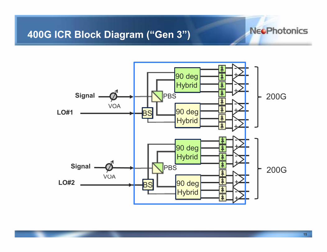
400G ICR Block Diagram (“Gen 3”)
90 deg
Hybrid
90 deg
HybridBS
PBS
+-
+-
+-
+-
LO#1
90 deg
Hybrid
90 deg
HybridBS
PBS
+-
+-
+-
+-
LO#2
200G
200G
Signal
VOA
VOA
Signal
16
Array of PICs for 400GE and 1T transceivers
● 2, 4, 5 or 10 array TLs
● 2, 4, 5 or 10 array ICTs
● 2, 4, 5 or 10 array ICRs
Challenges• Power consumption management
• Yield loss
• The number of pins for control and RF interfaces
• Skew management in interfacing with ADC/DAC

17
• Overview of Optical Transport Market
• Evolution of Coherent Optical Module
• PICs for Line-Side 400G Coherent Optical Modules and Linecards
• Tunable Laser
• Integrated Coherent Transmitter (ICT)
• Integrated Coherent Receiver (ICR)
• Array of TLs, ICTs & ICRs for 400GE/1T
• PIC for Client-Side 400G Optical Modules
• 25G EML
• Summary
18
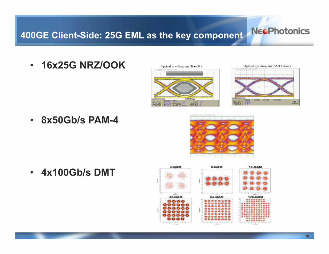
400GE Client-Side: 25G EML as the key component
• 16x25G NRZ/OOK
• 8x50Gb/s PAM-4
• 4x100Gb/s DMT

19
Summary
● Need standard or MSA for 400G and 1T optical modules
– Otherwise, a converged 100G industry will diverge again!
● 400G and 1T optical modules will require PICs, array of PICs, and multi-channel driver and TIA ICs
● Technical challenges for optical transceiver modules include:
– Power consumption
– Yield
– Interface with next-gen ADC’s and DAC’s (pitch, skew, amplitude, etc.)
– Numerous pins for control and RF interfaces


