1 Photonics in Telecom Satellite Payloads Nikos Karafolas with the kind contribution of colleagues in ESTEC and ESA’s industrial & academic contractors European Space Agency European Space Research and Technology Centre PO BOX 299 AG 2200 Noordwijk The Netherlands [email protected]
Transcript
1
Photonics in Telecom Satellite PayloadsNikos Karafolas
with the kind contribution of colleagues in ESTEC and ESA’s industrial & academic contractors
European Space AgencyEuropean Space Research and Technology Centre
Intra-satellite Photonics• Digital Communication links• Analog Communication links• Microwave Photonic Equipment
Extra-satellite Free Space Communications • Inter-satellite Communication links• Space-Ground-Space Communication links• Demonstrations
LECTURE-2
Optical Satellite Networking
3
History was written in parallel• October 4 1957, Sputnik, the first Satellite is launched• 16 May 1960, First working laser (Theodore Maiman – Hughes RL)• 19 August 1964, Syncom, the first GEO Telecom Satellite
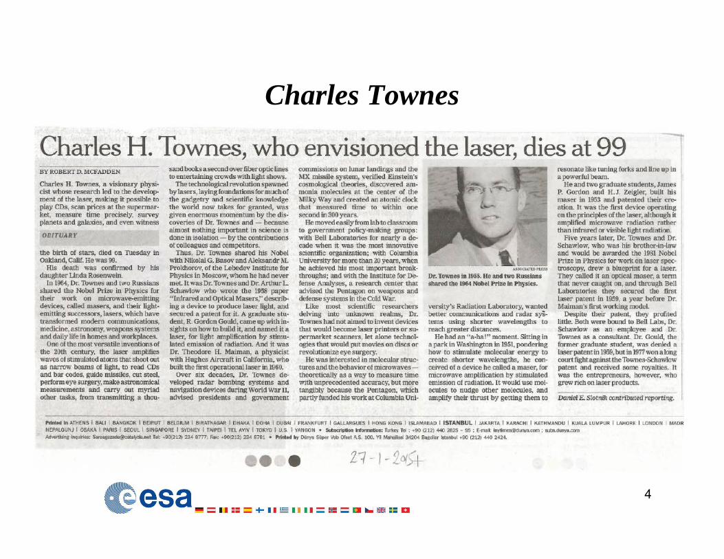
Charles Townes
4
5
Communication Satellites – COMSATs
Eurostar 3000 platform
COMSATs are repeaters in the sky
6
Primarily in GEO but also in MEO and LEO
7
8
and can be nodes in a global network
9
10
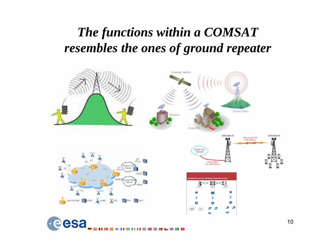
The functions within a COMSAT resembles the ones of ground repeater
11
A COMSAT can vary from being a classical Microwave Repeater (“bent pipe transponder”) to a full Digital Exchange Centre and can be a Node of a Network
ADC HPALNA
Digital Signal
Processor DoCon UpConDAC
Reference/ Master LO
ADC HPALNA
Digital Signal
Processor DoCon UpConDAC
Reference/ Master LO
(Alcatel RT 2Q2006)
12
Photonics in COMSAT PLs today
We need Optical Communications inside the Satellite because theintra-satellite communication requirements can reach several TbpsAlso because of the EMI, low mass, low volume and mechanicalflexibility characteristics of fibers that are important in for a Spacecraft
We need free-space laser links between satellites because the higherdirectivity of the optical beam allows higher data/power efficiency(more Mbps for each Watt of power) This is critical to power-limitedsystems like a S/C. However it has higher Pointing Acquisition andTracking requirements. We also need free space links that pass though theatmosphere and link satellites to (optical) Ground Stations to uplink or
downlink in high bit rates
Form a complete
“Optical Satellite Network”
interlinked with the terrestrial and submarine fiber optic networks
13
Photonics in COMSAT PLs tomorrow
Intra-Satellite Photonics
14
Satellite Platform and Payload
Any Satellite is composed by
• The Spacecraft (or Platform)• The Payload
We need a “Spacecraft” to place the “value added” “Payload” to the right place, give it power and keep it protected from the space environment
(radiation and thermal)
The target is always to maximise the Payload/Platform ratio
15
16
COMSAT Payloads can be massive…
17
Maximising the Payload output
Payloads will be restricted by an “envelop of available power-mass-volume”
In COMSAT the efficiency of the Payload is measured primarily in the
“cost of in orbit capacity delivery’
So we try to do things as efficiently as possible, i.eMinimise the power consumption
Minimise the massMinimise the volume
Minimise the S/C AIT (Assembly-Integration-Testing) time
18
19
Why considering Photonics
PHOTONICS PROPERTIES
• Practically limitless bandwidth (BW) as fiber optics offer an exploitable capacity of several THz at the band around 1550 nm
• Practically lossless propagation in an optical fiber within a spacecraft (S/C)• Transparency to any modulation/coding format• Immunity to Electromagnetic Interference (EMI)• Do not induce EMI• Are light weight, low volume• Are mechanically flexible • Are galvanically isolated
20
In Telecom Payloads we want
• to reduce the mass-volume-power of the PL compared to the S/C • to enable new functionalities such as dynamic allocation of the on
board resources
Therefore • we study the applicability of photonic technologies in the 5 main
equipment of the “low-power” section of a Telecom PLBut• we do not consider them for the “high-power” section where
photonics are not suitable
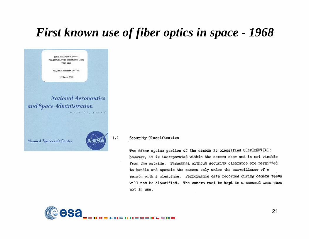
First known use of fiber optics in space - 1968
21
Where do we use Photonics in a COMSAT PL?
• Digital Links in Digital Payloads
• Analog Links in all types of Payloads
• Microwave Photonic Equipment mostly in Analog Payloads• Frequency Generation Units• Frequency Conversion Units• Switching Units• Beam Forming Units • RF filtering units
22
23
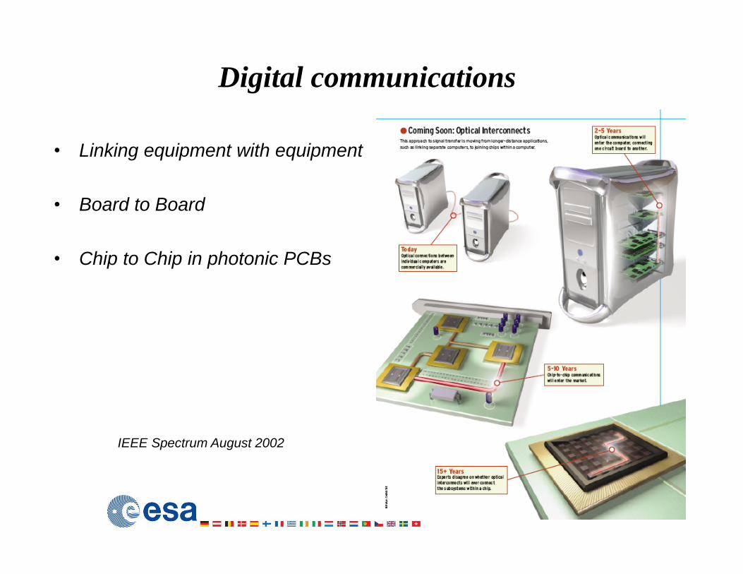
Digital communications
• Linking equipment with equipment
• Board to Board
• Chip to Chip in photonic PCBs
IEEE Spectrum August 2002
24
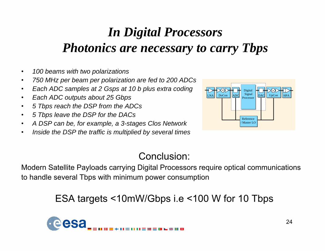
In Digital ProcessorsPhotonics are necessary to carry Tbps
• 100 beams with two polarizations• 750 MHz per beam per polarization are fed to 200 ADCs• Each ADC samples at 2 Gsps at 10 b plus extra coding• Each ADC outputs about 25 Gbps• 5 Tbps reach the DSP from the ADCs• 5 Tbps leave the DSP for the DACs• A DSP can be, for example, a 3-stages Clos Network• Inside the DSP the traffic is multiplied by several times
Conclusion:Modern Satellite Payloads carrying Digital Processors require optical communications to handle several Tbps with minimum power consumption
ESA targets <10mW/Gbps i.e <100 W for 10 Tbps
ADC HPALNA
Digital Signal
Processor DoCon UpConDAC
Reference/ Master LO
ADC HPALNA
Digital Signal
Processor DoCon UpConDAC
Reference/ Master LO
25
A Photonicaly interconnected 10 Tbps Digital Payload Demonstrator
TAS’s DTP 2nd Generation can host 1000 fiber links at 10 Gbps each linked with an optical interconnection flexible plane
26
The technological basis for digital communications
• Tx: VCSELs (850nm) (GaAs) • Rx: Pin (850nm) (GaAs – more rad-hard)• Modulation: Direct modulation• Fibers: GIMM • Fiber Cables: Single and Ribbon Fiber • Cable jackets: (no out gassing) • Connectors: With anti-vibration mechanism for both parallel and single fiber• No amplifiers are employed (max distance of 100 m for the ISS, typ. <10m)• Parallel Tx/Rx Modules are currently preferred over WDM for reliability
reasons
27
Single and Parallel Digital Optical Tx/Rx
ADC-DSP-DAC
Board to Board inside the DSP
(N. Venet, ICSO 2004)
28
First operational use of fiber optic links in Space was in the International Space Station
decision taken in late 80’stechnologies of 90’s
29
SMOS (Soil Moisture and Ocean Salinity):first Satellite Payload to rely critically on fiber optics
(in orbit since 11/2009)
• very low EM emission levels (from Tx/Rx)
• galvanic isolation
• mechanically flexible and lightweight
• better phase stability when bended
144 links at 110 Mbps (72 to and 72 from antenna elements)
Optical Analog Links
communications:
• Distribution of a LO (with minimal added phase noise) between the Frequency Generation Unit to Frequency Converter
• Analog links between • INPUT LNA -Frequency Converter • Frequency Converter - SWITCH • SWITCH - FILTERS or OUTPUT TWTA
30
31
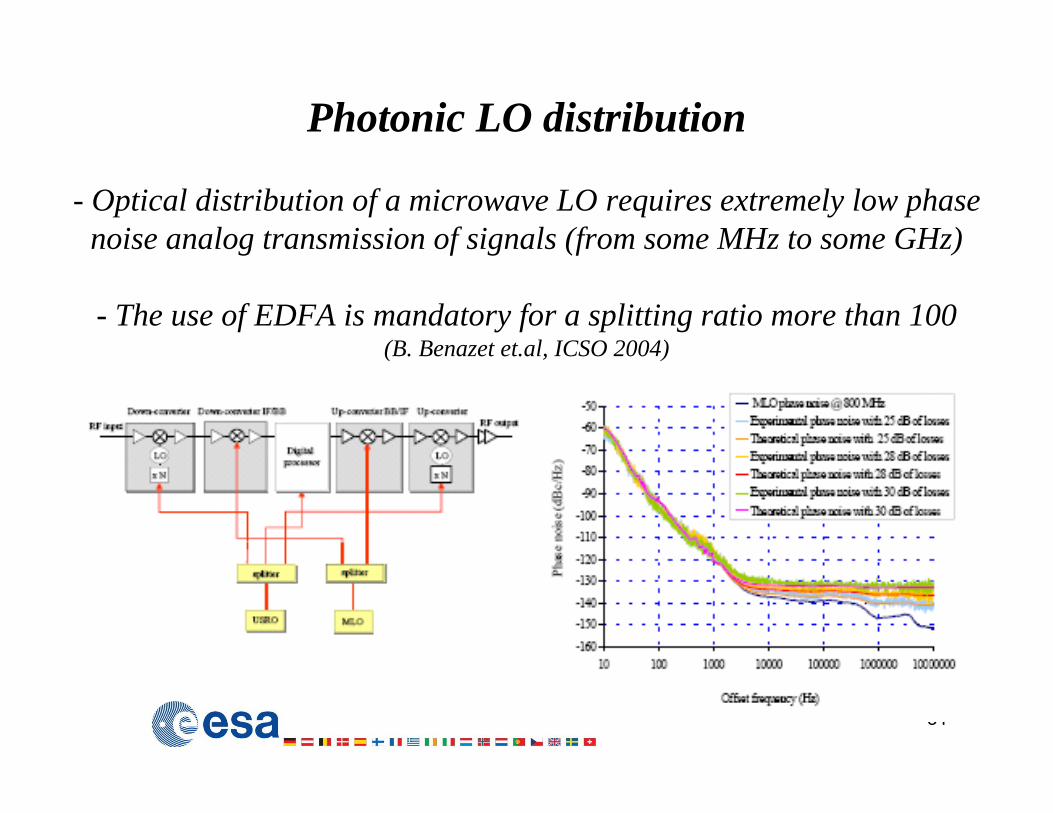
Photonic LO distribution
- Optical distribution of a microwave LO requires extremely low phase noise analog transmission of signals (from some MHz to some GHz)
- The use of EDFA is mandatory for a splitting ratio more than 100 (B. Benazet et.al, ICSO 2004)
First flight demonstration of an analog linkIn February 2000, the Space Shuttle “Endevaour” flew for 11 days a
5.3 GHz fiber optic link linking an antenna on a 60 m boom to equipment in the shuttle bay
32
33
In Analog Payloads Photonics are considered for:
Frequency generation, conversion and distribution&switching
34
And extend to more elaborated architectures with photonic Beam Forming Networks and photonic RF filtering
Frequency Generation Unit
35
36
Frequency Conversion Unit
Circuit Switch Unit
37
Beam Forming Network
38
RF filtering Unit
39
40
Photonic Technologies BasisMZI optical modulators as used as “mixers” for downconversion
MOEMS as the crossconnect switchEDFAs for high splitting ration in LO distribution
The benefits of introducing Photonics in COMSAT PL
41
Which results in significantly increased revenueSavings in mass
can be converted in extra fuel for extra years of operation
which can lead to hundreds of Meuros extra revenue for an operator
The average cost of a 36 MHz transponder is 1.62 Meuro/year A satellite can have several tens of transponders
A year of operation offers tens/hundreds of Meuros in revenue
42
COMSATs is a multibillion business...and a small investment in a new technology in satellite manufacturing
can lead to a big return in revenue from value-adding-services…
43
Extra-Satellite Laser Communications
• Inter-satellite Links
• Space-Ground-Space optical Links
• Demonstrations
main reference spurce:“ESA’s Optical Ground Station & Laser Communication Activities”Plenary Talk by Zoran Sodnik at ICSO 2014www.icsoproceedings.org
44
45
Inter-satellite Optical Communications
Frequency Generation Unit to Frequency Converter
46
What was first?
• Waveguided (fiber optics)• Atmospheric • Space
Optical Communications?
47
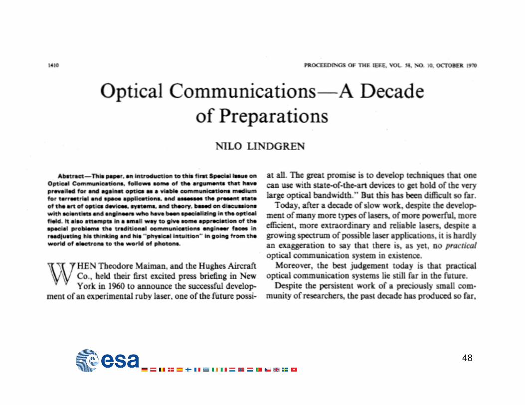
48
49
“…fiber optic losses…would amount to thousands of dBs per mile” –
“by 1973…at least one satellite would be…carrying laser comms experiments..”
“Free-Space” Optical Communications
50
Require 2 Laser Communication Terminals each composed of:
Electromagnetic radiation does not propagate in a straight line. If the transmitter system is perfect, diffraction will increase the beam size if transmitted over distance.
Diffraction limited beam divergence angle: / D
EXAMPLE:Radio Ka-band wavelength: λ=12000 µm (25 GHz)Laser wavelength: λ=1.5 µmDivergence angle ratio: Ka / L 7742Illuminated area ratio: (Ka / L)2 ---> AKa / AL 59 000 000 = 78 dB
Laser communication can deliver (concentrate) 59 Millions times more power than a Ka communication from a transmit to a receiv terminal of same diameters.
But laser communication terminal needs to point 7742 times more accurately than a Ka-band terminal of same diameter.
Fundamental Concepts
Small Angles - Divergence & Spot Size
1 μrad
X 1000km
1 m
Small angle approximation:
Angle (in microradians) * Range (1000 km)= Spot Size (m)
Divergence Range Spot Diameter1 μrad 40 x 1000 km ~ 40 m
10 μrad 40 x 1000 km ~ 400 m
1° ≈ 1700 μrad → 1 μrad ≈ 0.0000573°
PointingEach terminal needs
first
• to know where the counter-terminal is using –uploaded ephemeris data of corresponding satellite, –GPS
(this is uploaded by telemetry to each S/C)
then it applies
• Pointing- Acquisition & Tracking (PAT) of the counter-terminal• Course PAT• Fine PAT
54
55
56
Pointing Acquisition and Trackingpoint ahead!
ESA’s OGSSILEX Acquisition Strategy (1)
Scan FOV: 5796 x 5472 rad Rx FOV (diam): 2327 radScan interval: 316 radRx FOV: 1050 x 1050 radBeacon FOV: diam. 750 radBeacon wavelength: 801 nm
ARTEMIS OGS (or LEO satellite)
ESA’s OGSSILEX Acquisition Strategy (2)
Scan duration: 208 s Response time: <0.35 sBeacon FOV (diam): 750 rad Laser FOV (diam): 27 radFar-Field illumination: 0.75 s Laser wavelength: 847 nmBeacon wavelength: 801 nm Laser power: 3 WMax. beacon power: 19 x 900 mW
Remember in free-space there is nor fiber-induce phenomena• No dispersion i.e we can use very high data rate • No non-linearities i.e we can use very high data rate
63
64
Ground-Satellite-Ground Optical Communications
65
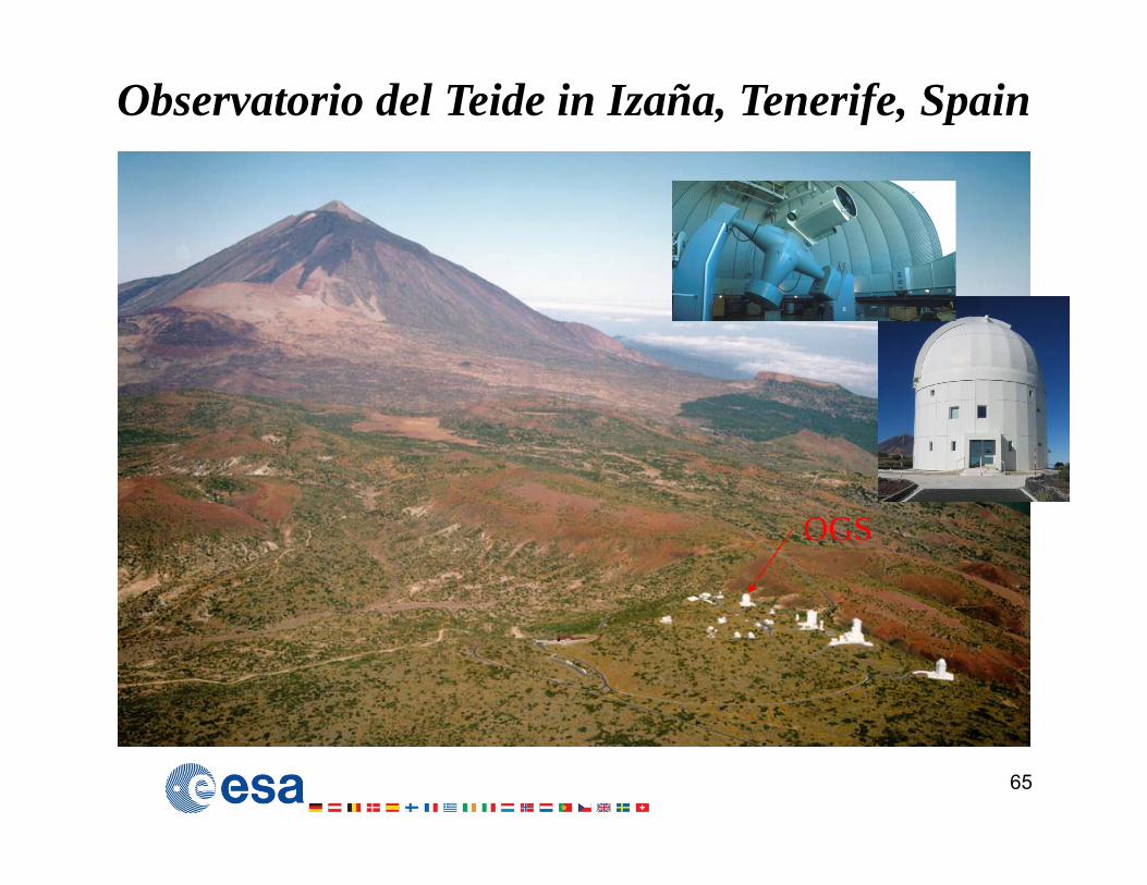
Observatorio del Teide in Izaña, Tenerife, Spain
OGS
66
Inter-satellite link
Ground-satellite link
The effect of propagation through the atmosphere
Extension of turbulent atmosphere: 20 km -> (is smaller than the line-width of the drawing)
Atmospheric turbulence effects on the propagation of a coherent laser beam decrease with height above ground.
SCINTILLATION• Beam spreading and wandering due to propagation through air pockets of
varying temperature, density, and index of refraction.• Results in increased error rate but not complete outage• Almost exclusive with fog attenuation.
The beam broadens and it is distorted in phases“Shower Curtain Effect”
The signal at the Satellite terminal is distorted far more than the one in the Ground terminalvities
Mitigate scintillation by multiple incoherent transmitters
70
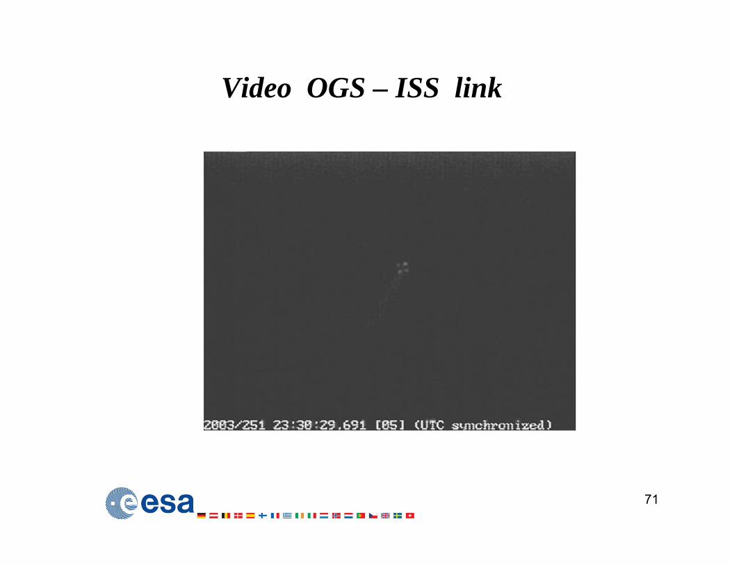
Video OGS – ISS link
71
72
Applications of ISLs 1. Data Relay (like the Tracking and Data Relay Satellites that serve the Space Shuttle)
(Mbps from a LEO/GEO satellite or aircraft to earth via another GEO satellite) 2. For Space Science Links (Mbps or Kbps over millions of kms)(between Lagrange Points or Interplanetary Probes Space to OGSs or GEO)3. For Broadband (multigigabit) links (over thousands of Kms) in Telecom
Constellations among S/C in LEO/MEO/GEO
Technologies• Europe: First Generation of terminals were in 800-850nm band-ASK(PPM)-
Direct Detection• Europe: Second Generation were in 1064nm-BPSK-Coherent Detection• In USA: 1550nm-ASK-Direct Detection has been studied and demonstrated
73
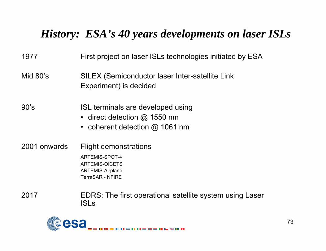
History: ESA’s 40 years developments on laser ISLs
1977 First project on laser ISLs technologies initiated by ESA
Mid 80’s SILEX (Semiconductor laser Inter-satellite LinkExperiment) is decided
90’s ISL terminals are developed using • direct detection @ 1550 nm • coherent detection @ 1061 nm
2017 EDRS: The first operational satellite system using Laser ISLs
74
Flying S/C equipped with ISL terminals
• ETS (JAXA) in GTO ( 1 Mbps-DD)• SPOT-4 (CNES) in LEO (50Mbps-850nm-DD)• ARTEMIS (ESA) in GEO (50Mbps-850nm-DD)• GeoLITE (USA) in GEO (military - confidential)• OICETS (JAXA) in LEO (50Mbps-850nm-DD)• TerraSAR-X (DLR) in LEO (5.5Gbps-1064nm-CD)• NFIRE (USA) in LEO (5.5Gbps-1064nm-CD)
ESA maintains an Optical Ground Station in Tenerife, Spain to supportexperiments for Ground-Space links
SILEX First generation optical data relay
SILEX inter satellite link between SPOT-4 (LEO) and ARTEMIS (GEO)
76
SILEX Parameters
ARTEMIS SPOT-4
Antenna diameter Rx: 250 mm 250 mm
Beam diameter Tx (1/e2): 125 mm 250 mm
Transmit power: 5 mW 40 mW
Transmit data rate: 2 Mbps 50 Mbps
Transmit wavelength: 819 nm 847 nm
Transmit modulation scheme: 2-PPM NRZ
Receive data rate: 50 Mbps none
Receive wavelength: 847 nm 819 nm
Receive modulation scheme: NRZ none
Link distance: <45000 km
Beacon wavelength: 801 nm none
Optical terminal weight: 160 kg 150 kg
ARTEMIS to OGS to ARTEMIS …… VIDEO!
77
ARTEMIS TO SPOT-4
78
79
First Image Transmitted by SILEX data relay
30 November 2001 17:45 Lanzarote, Canary Islands, in the Atlantic ocean west of Africa, the first image transmitted via optical intersatellite link from SPOT4 to ARTEMIS and then to SPOTIMAGE in Toulouse, France via ARTEMIS’ Ka-band feeder link
80
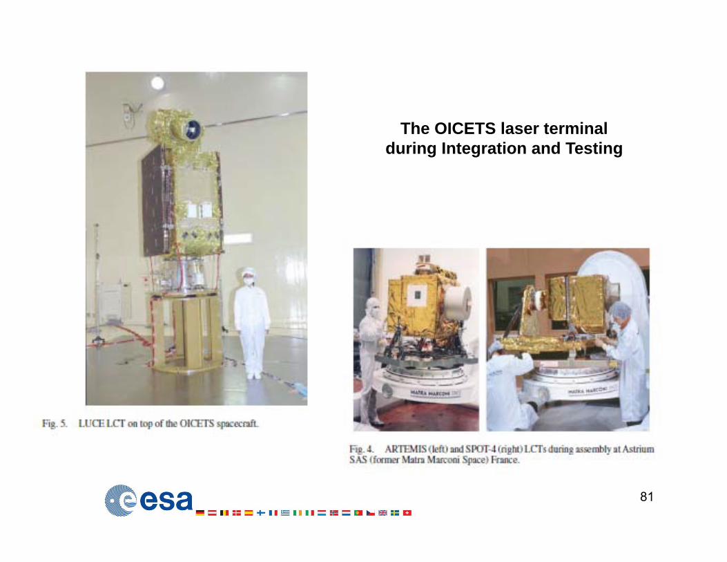
ARTEMIS and the OICETS LinkDec. 2005: First bi-directional optical inter-satellite link
81
The OICETS laser terminal during Integration and Testing
82
DLR OGS – OICETS Optical Communications
83
ARTEMIS and the Airplane links (flying over Cote d’ Azur)
Summary of first generation optical ISL terminals
ARTEMIS SPOT-4 OICETS LOLA
Orbit and launch date: GEO - 2001 LEO - 1998 LEO - 2005 NA - 2006
Antenna diameter Rx: 250 mm 250 mm 260 mm 125 mm
Beam diameter Tx (1/e2): 125 mm 250 mm 130 mm 73 mm
Transmit power (ex aperture): 5 mW 40 mW 70 mW 104 mW
Transmit data rate: 2 Mbps 50 Mbps
Transmit wavelength: 819 nm 847 nm 847 nm 847 nm
Transmit modulation scheme: 2-PPM OOK - NRZ OOK - NRZ OOK - NRZ
Receive data rate: 50 Mbps none 2 Mbps 2 Mbps
Receive wavelength: 847 nm 819 nm 819 nm 819 nm
Receive modulation scheme: OOK - NRZ none OOK 2-PPM OOK 2-PPM
Link distance: <45000 km
Beacon wavelength: 801 nm none none none
Optical terminal mass: 160 kg 150 kg 160 kg 50 kg
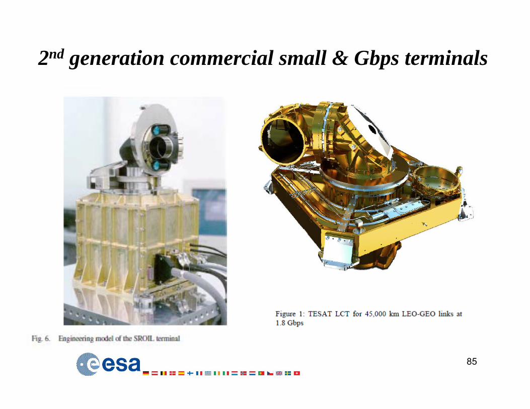
2nd generation commercial small & Gbps terminals
85
86
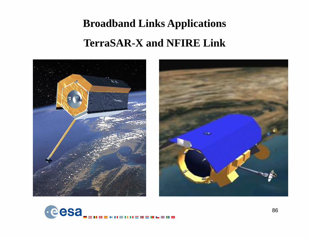
Broadband Links Applications
TerraSAR-X and NFIRE Link
87
89
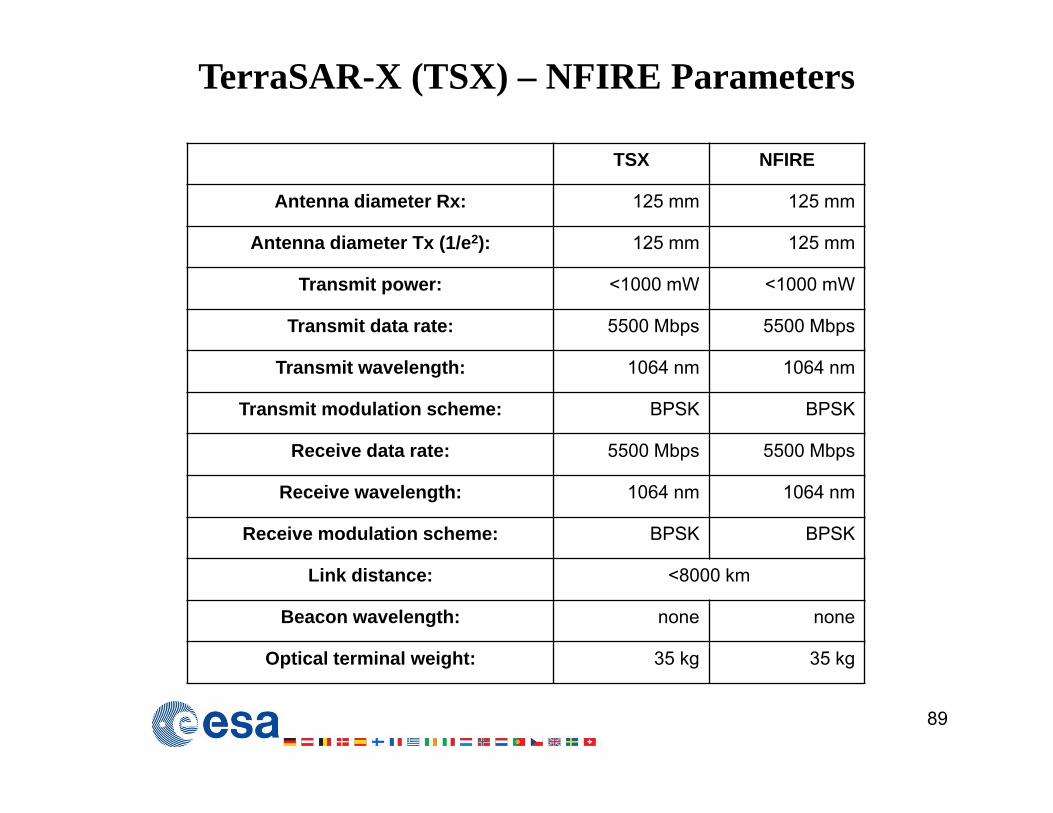
TerraSAR-X (TSX) – NFIRE Parameters
TSX NFIRE
Antenna diameter Rx: 125 mm 125 mm
Antenna diameter Tx (1/e2): 125 mm 125 mm
Transmit power: <1000 mW <1000 mW
Transmit data rate: 5500 Mbps 5500 Mbps
Transmit wavelength: 1064 nm 1064 nm
Transmit modulation scheme: BPSK BPSK
Receive data rate: 5500 Mbps 5500 Mbps
Receive wavelength: 1064 nm 1064 nm
Receive modulation scheme: BPSK BPSK
Link distance: <8000 km
Beacon wavelength: none none
Optical terminal weight: 35 kg 35 kg
ALPHASAT to OGS
90
Acquisition, pointing and tracking from ESA’s Optical Ground Station (OGS) until LCT on Sentinel 1a is ready:
• 2.0 W transmit power• 13.5 cm transmit aperture• 1.8 Gbps over 45000 km
91
EDRS: The first operational use of Laser ISLs(remember ARTEMIS-SPOT4/OICETS 10 years earlier)
92
Optical links serving Space Science Missions …….beyond GEO
• Moon Links
• Links at the L2 point
• Interplanetary links
93
94
the Moon link 400.000 Kms
Moon-Earth (OGS) simulated link by RUAG in ESA’s DOLCE project
the LADEE-OGS Moon Link (September 2014)
95
LADEE spacecraft downlink to ESA’s Optical Ground Station (OGS):• 80 Mbps over 400000 km• 0.5 W transmit power• 10 cm transmit aperture• 1 meter receive aperture
Multiple smaller telescopes to compensate for atmospheric turbulence
96
97
The L2 point (1.5 million kms):a parking place for Space Science Telescopes
RUAG, CH.
GOPEX: Galileo Optical Experiment
98
In December 1992 optical links experiments were performed between OGSs in the US and the Galileo Spacecraft (which was on its way to Jupiter). At its longing span the link was 6 Million kms
GOPEX: Galileo Optical Experiment
99
Two sets of laser pulses transmitted from Earth to a spacecraft over a distance of 1.4 million kilometers (870,000 miles) in a communications experiment are shown in this long-exposure image made by the Galileo spacecraft's imaging system. In the image, taken on Dec. 10 1992, second day of the 8-day experiment, the sunlit part of the planet (west central United States) is to the right, the night side to the left. The camera was scanned from bottom to top of the frame (approximately south to north), smearing terrain features but showing individual pulses. The five larger spots in a vertical column near the pre-dawn centerline of the frame represent pulses from the U.S. Air Force Phillips Laboratory's Starfire Optical Range near Albuquerque, NM, at a pulse rate of 10 Hz. Those to the left are from the Jet Propulsion Laboratory's Table Mountain Observatory near Wrightwood, CA, at a rate of 15 Hz. Spots near the day/night terminator to the right are noise events not associated with the laser transmissions. The experiment, called GOPEX (Galileo Optical Experiment), is demonstrating a laser "uplink" from Earth to spacecraft. Laser "downlinks" may be used in the future to send large volumes of data from spacecraft to Earth. The experiment was operated by JPL's Tracking and Data Acquisition Technology Development Office for NASA's Office of Space
Communications Advanced Systems Proqram.
The Mercury Messenger Link - 24 million km !
Photonics Spectra May 2006
The LIDAR calculated the distance of about 24 million km with an accuracy of 20cm ! 23.964.675.433.9 m +/- 20 cm
Laser tests were successful despite the clouds at the NASA Goddard SFC Geophysical and Astrophysical Observatory on May 31, 2005
Laser pulses emitted from the Mercury Laser Altimeter aboard the Messenger spacecraft, 24 million kilometers from Earth, were detected at the observatory
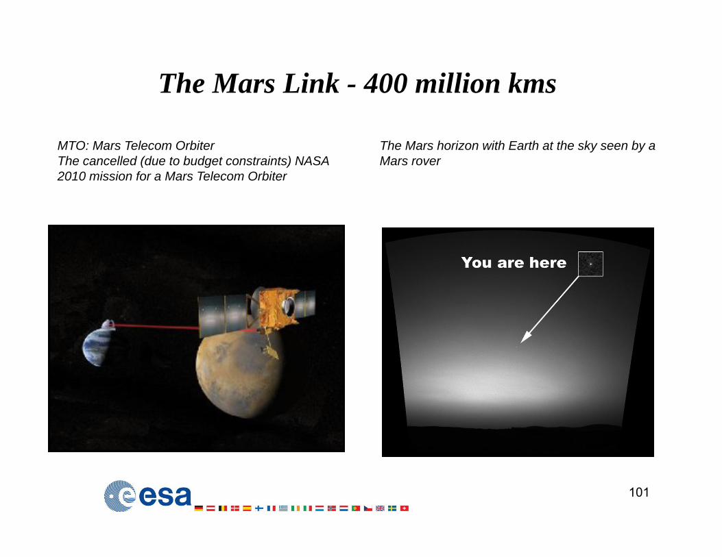
The Mars Link - 400 million kms
101
MTO: Mars Telecom OrbiterThe cancelled (due to budget constraints) NASA 2010 mission for a Mars Telecom Orbiter
The Mars horizon with Earth at the sky seen by a Mars rover
Summary in Extra-Satellite Optical Links
102
• Intersatellite links have been demonstrated offering Gbps communications • ISL terminals are commercially available• The EDRS is the first operational system
• Space to Ground links have been demonstrated• Space to Ground Links suffer from the atmospheric propagation effects• Spatial Diversity of OGS can increase substantially the link availability
• Inter-linking a number of satellites and OGS with ISLs and GSLs can enable the use of a global optical space network either self-sustained or linked with the terrestrial and submarine fiber optical network.
Summary of Photonics in COMSAT PLs
A portfolio of photonic technologies and techniques have matured to high TRL in
• intra-satellite communication links • photonic equipment for a number of functions • inter-satellite links • satellite to ground to satellite links
The combination of these technologies/techniques enable a number of COMSAT Payload scenarios and Systems. The most advanced of these Systems make use of ISLs with On-board Optical Switching enabling the establishment of: