20
1 Photovoltaic Content Photovoltaic Inverter Page xx DC-Disconnection Page xx DC-String Protection Page xx Surge Protection Page xx Energy Management Page xx

1
Photovoltaic
Content Photovoltaic
Inverter Page xx
DC-Disconnection Page xx
DC-String Protection Page xx
Surge Protection Page xx
Energy Management Page xx
2
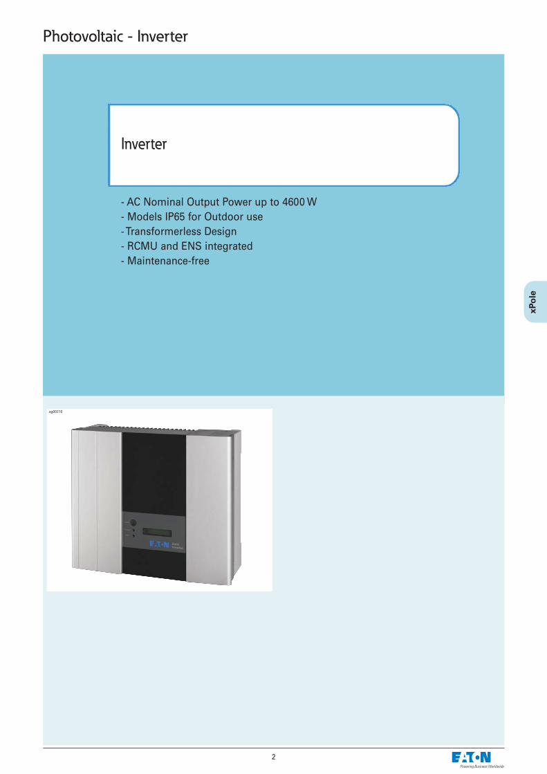
- AC Nominal Output Power up to 4600 W- Models IP65 for Outdoor use- Transformerless Design- RCMU and ENS integrated- Maintenance-free
Inverter
Photovoltaic - Inverter
sg00210
3
Photovoltaic - Inverter
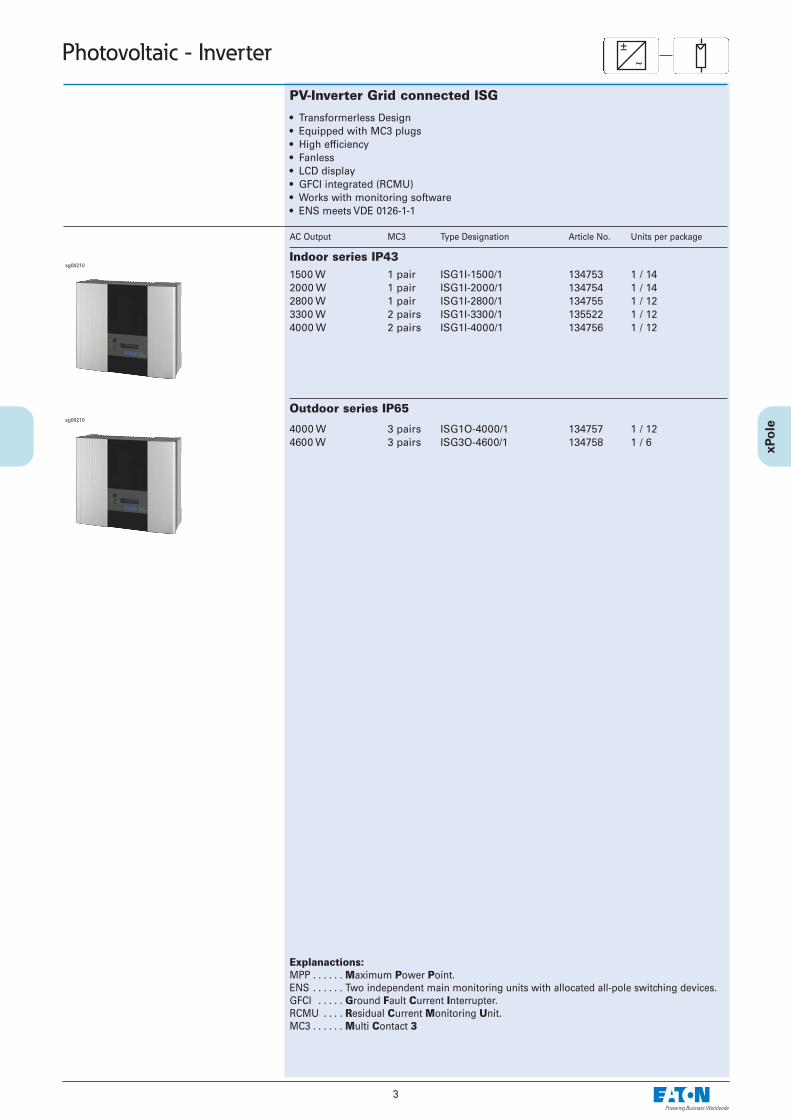
PV-Inverter Grid connected ISG
1500 W 1 pair2000 W 1 pair2800 W 1 pair3300 W 2 pairs4000 W 2 pairs
ISG1I-1500/1 134753 1 / 14ISG1I-2000/1 134754 1 / 14ISG1I-2800/1 134755 1 / 12ISG1I-3300/1 135522 1 / 12ISG1I-4000/1 134756 1 / 12
Outdoor series IP65
4000 W 3 pairs4600 W 3 pairs
ISG1O-4000/1 134757 1 / 12ISG3O-4600/1 134758 1 / 6
±~
Indoor series IP43
sg00210
sg00210
• Transformerless Design• Equipped with MC3 plugs• High efficiency• Fanless• LCD display• GFCI integrated (RCMU)• Works with monitoring software• ENS meets VDE 0126-1-1
AC Output MC3 Type Designation Article No. Units per package
Explanactions:MPP . . . . . . Maximum Power Point. ENS . . . . . . Two independent main monitoring units with allocated all-pole switching devices.GFCI . . . . . Ground Fault Current Interrupter. RCMU . . . . Residual Current Monitoring Unit. MC3 . . . . . . Multi Contact 3
4
Photovoltaic - Inverter ITALY
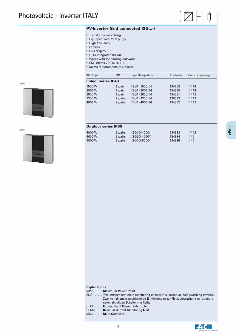
PV-Inverter Grid connected ISG...-I
1500 W 1 pair2000 W 1 pair2800 W 1 pair3300 W 2 pairs4000 W 2 pairs
ISG1I-1500/1-I 134759 1 / 14ISG1I-2000/1-I 134830 1 / 14ISG1I-2800/1-I 134831 1 / 12ISG1I-3300/1-I 135523 1 / 12ISG1I-4000/1-I 134832 1 / 12
Outdoor series IP65
4000 W 3 pairs4600 W 3 pairs6000 W 3 pairs
ISG1O-4000/1-I 134833 1 / 12ISG3O-4600/1-I 134834 1 / 6ISG1O-6000/1-I 134835 1 / 6
±~
Indoor series IP43
sg00210
sg00210
• Transformerless Design• Equipped with MC3 plugs• High efficiency• Fanless• LCD display• GFCI integrated (RCMU)• Works with monitoring software• ENS meets VDE 0126-1-1• Meets requirements of DK5940
AC Output MC3 Type Designation Article No. Units per package
Explanations:MPP . . . . . . Maximum Power PointENS . . . . . . Two independent main monitoring units with allocated all-pole switching devices.
Zwei voneinander unabhängige Einrichtungen zur Netzüberwachung mit zugeord-neten allpoligen Schaltern in Reihe.
GFCI . . . . . Ground Fault Current InterrupterRCMU . . . . Residual Current Monitoring UnitMC3 . . . . . . Multi Contact 3
5
Photovoltaic - Inverter
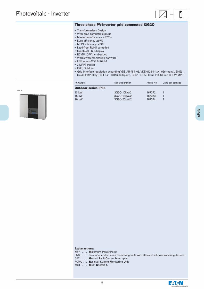
Three-phase PV-Inverter grid connected I3G2O
10 kW15 kW20 kW
I3G2O-10kW/2 167372 1I3G2O-15kW/2 167373 1I3G2O-20kW/2 167374 1
±~
Outdoor series IP65sg00210
• Transformerless Design• With MC4 compatible plugs• Maximum efficiency ≥97.5%• Euro efficiency ≥97% • MPPT efficiency >99%• Lead-free, RoHS complied • Graphical LCD display• RCMU (GFCI) embedded• Works with monitoring software• ENS meets VDE 0126-1-1• 2 MPPT-tracker• IP65, Outdoor• Grid interface regulation according VDE-AR-N 4105, VDE 0126-1-1/A1 (Germany), ENEL
Guide 2012 (Italy), CEI 0-21, RD1663 (Spain), G83/1-1, G59 Issue 2 (UK) and BDEW(MVD)
AC Output Type Designation Article No. Units per package
Explanactions:MPP . . . . . . Maximum Power Point. ENS . . . . . . Two independent main monitoring units with allocated all-pole switching devices.GFCI . . . . . Ground Fault Current Interrupter. RCMU . . . . Residual Current Monitoring Unit. MC4 . . . . . . Multi Contact 4
6
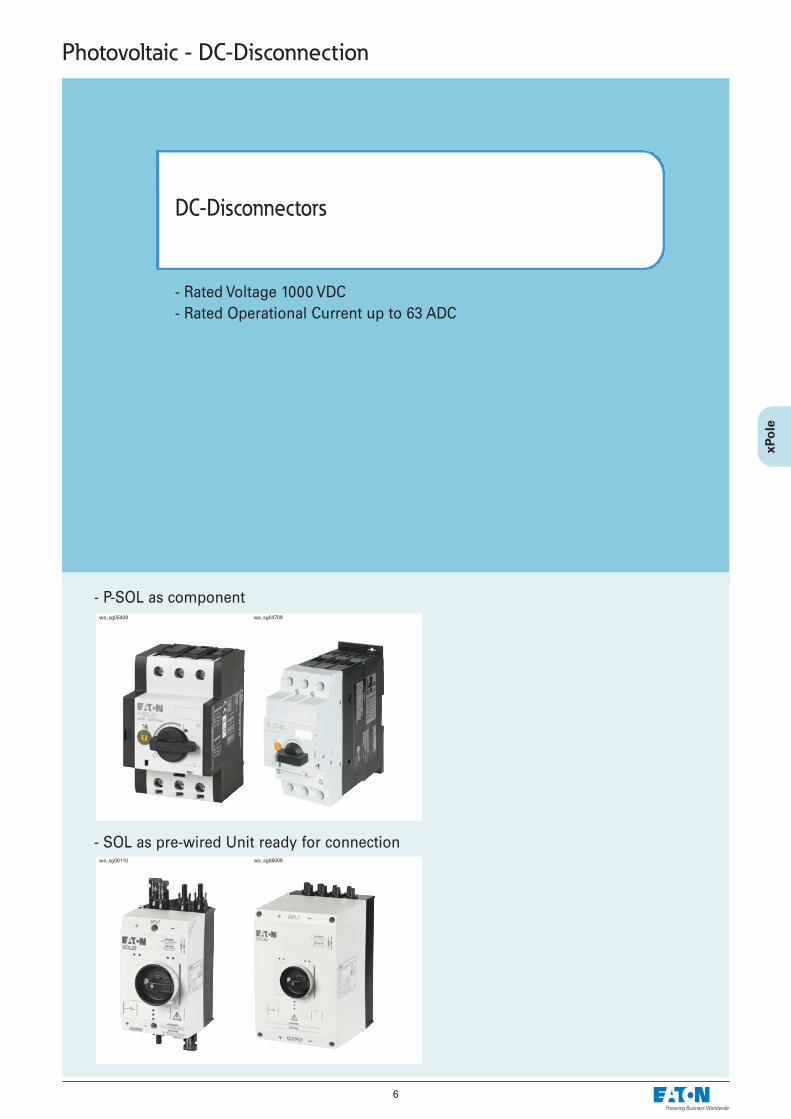
- Rated Voltage 1000 VDC- Rated Operational Current up to 63 ADC
DC-Disconnectors
Photovoltaic - DC-Disconnection
- P-SOL as component
- SOL as pre-wired Unit ready for connection
wa_sg05409 wa_sg04709
wa_sg00110 wa_sg06009
7
Photovoltaic - DC-Disconnection DC
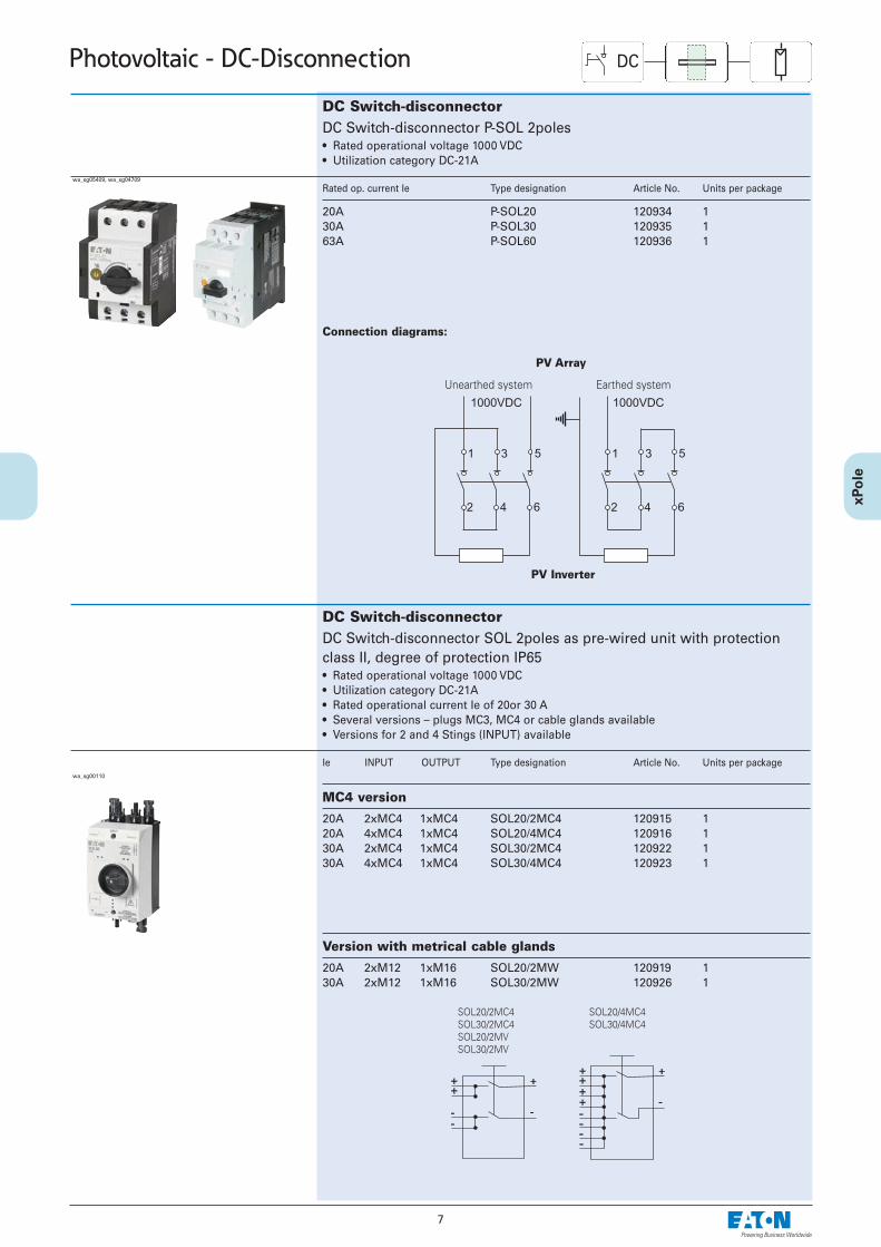
DC Switch-disconnectorDC Switch-disconnector P-SOL 2poles • Rated operational voltage 1000 VDC• Utilization category DC-21A
Rated op. current Ie Type designation Article No. Units per package
20A30A63A
P-SOL20 120934 1P-SOL30 120935 1P-SOL60 120936 1
wa_sg05409, wa_sg04709
Connection diagrams:
PV Array
Unearthed system Earthed system
PV Inverter
DC Switch-disconnectorDC Switch-disconnector SOL 2poles as pre-wired unit with protectionclass II, degree of protection IP65• Rated operational voltage 1000 VDC• Utilization category DC-21A• Rated operational current Ie of 20or 30 A• Several versions – plugs MC3, MC4 or cable glands available• Versions for 2 and 4 Stings (INPUT) available
Ie INPUT OUTPUT Type designation Article No. Units per package
SOL20/2MC4SOL30/2MC4SOL20/2MVSOL30/2MV
SOL20/4MC4SOL30/4MC4
MC4 version
20A 2xMC4 1xMC420A 4xMC4 1xMC430A 2xMC4 1xMC430A 4xMC4 1xMC4
SOL20/2MC4 120915 1SOL20/4MC4 120916 1SOL30/2MC4 120922 1SOL30/4MC4 120923 1
Version with metrical cable glands
20A 2xM12 1xM1630A 2xM12 1xM16
SOL20/2MW 120919 1SOL30/2MW 120926 1
wa_sg00110
8
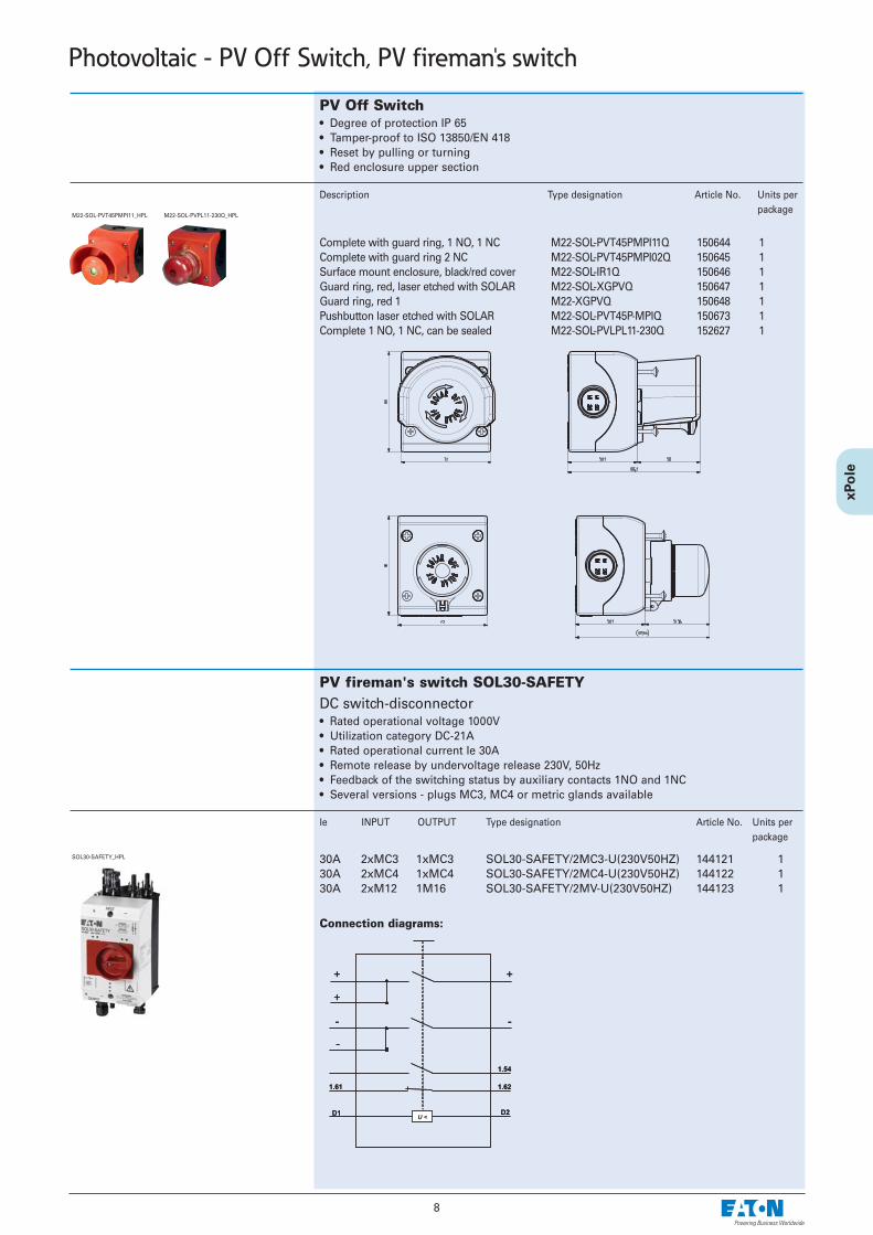
Connection diagrams:
PV fireman's switch SOL30-SAFETYDC switch-disconnector• Rated operational voltage 1000V• Utilization category DC-21A• Rated operational current Ie 30A• Remote release by undervoltage release 230V, 50Hz• Feedback of the switching status by auxiliary contacts 1NO and 1NC• Several versions - plugs MC3, MC4 or metric glands available
Ie INPUT OUTPUT Type designation Article No. Units per package
SOL30-SAFETY_HPL 30A 2xMC3 1xMC330A 2xMC4 1xMC430A 2xM12 1M16
SOL30-SAFETY/2MC3-U(230V50HZ) 144121 1SOL30-SAFETY/2MC4-U(230V50HZ) 144122 1SOL30-SAFETY/2MV-U(230V50HZ) 144123 1
Photovoltaic - PV Off Switch, PV fireman's switch
PV Off Switch• Degree of protection IP 65• Tamper-proof to ISO 13850/EN 418• Reset by pulling or turning• Red enclosure upper section
Description Type designation Article No. Units perpackage
M22-SOL-PVT45PMPI11_HPL M22-SOL-PVPL11-230Q_HPL
Complete with guard ring, 1 NO, 1 NCComplete with guard ring 2 NCSurface mount enclosure, black/red coverGuard ring, red, laser etched with SOLARGuard ring, red 1Pushbutton laser etched with SOLARComplete 1 NO, 1 NC, can be sealed
M22-SOL-PVT45PMPI11Q 150644 1M22-SOL-PVT45PMPI02Q 150645 1M22-SOL-IR1Q 150646 1M22-SOL-XGPVQ 150647 1M22-XGPVQ 150648 1M22-SOL-PVT45P-MPIQ 150673 1M22-SOL-PVLPL11-230Q 152627 1
9
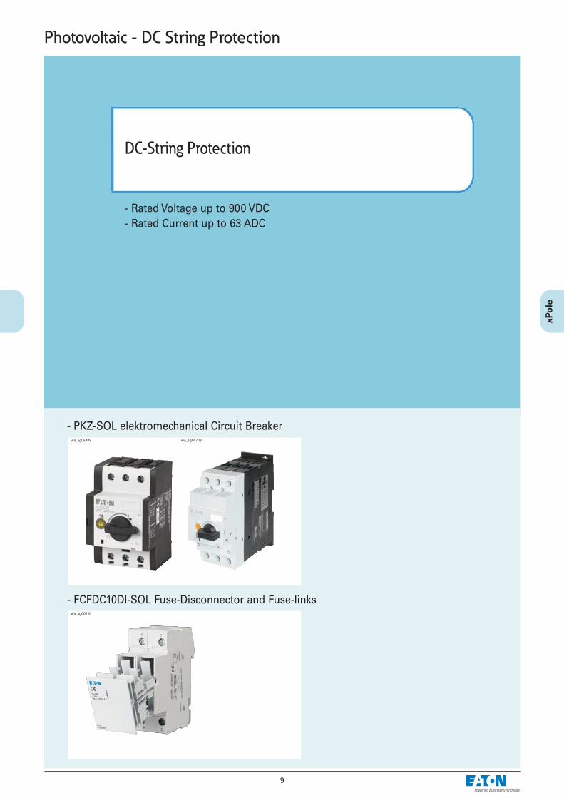
- Rated Voltage up to 900 VDC- Rated Current up to 63 ADC
DC-String Protection
Photovoltaic - DC String Protection
- PKZ-SOL elektromechanical Circuit Breaker
- FCFDC10DI-SOL Fuse-Disconnector and Fuse-links
wa_sg05409 wa_sg04709
wa_sg00210
10
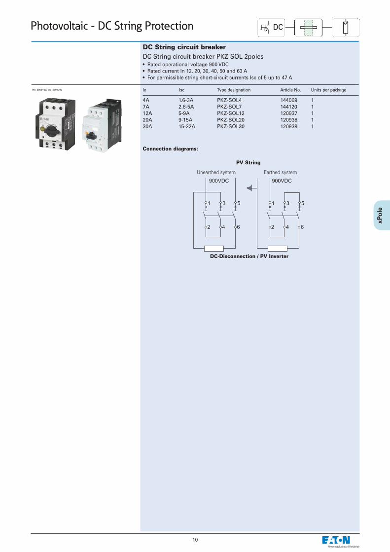
Photovoltaic - DC String Protection
DC String circuit breakerDC String circuit breaker PKZ-SOL 2poles • Rated operational voltage 900 VDC• Rated current In 12, 20, 30, 40, 50 and 63 A• For permissible string short-circuit currents Isc of 5 up to 47 A
Ie Isc Type designation Article No. Units per package
4A 1.6-3A7A 2.6-5A12A 5-9A20A 9-15A 30A 15-22A
PKZ-SOL4 144069 1PKZ-SOL7 144120 1PKZ-SOL12 120937 1PKZ-SOL20 120938 1PKZ-SOL30 120939 1
Connection diagrams:
PV String
Unearthed system Earthed system
DC-Disconnection / PV Inverter
DC
wa_sg05409, wa_sg04709
11
Photovoltaic - DC String Protection CDC
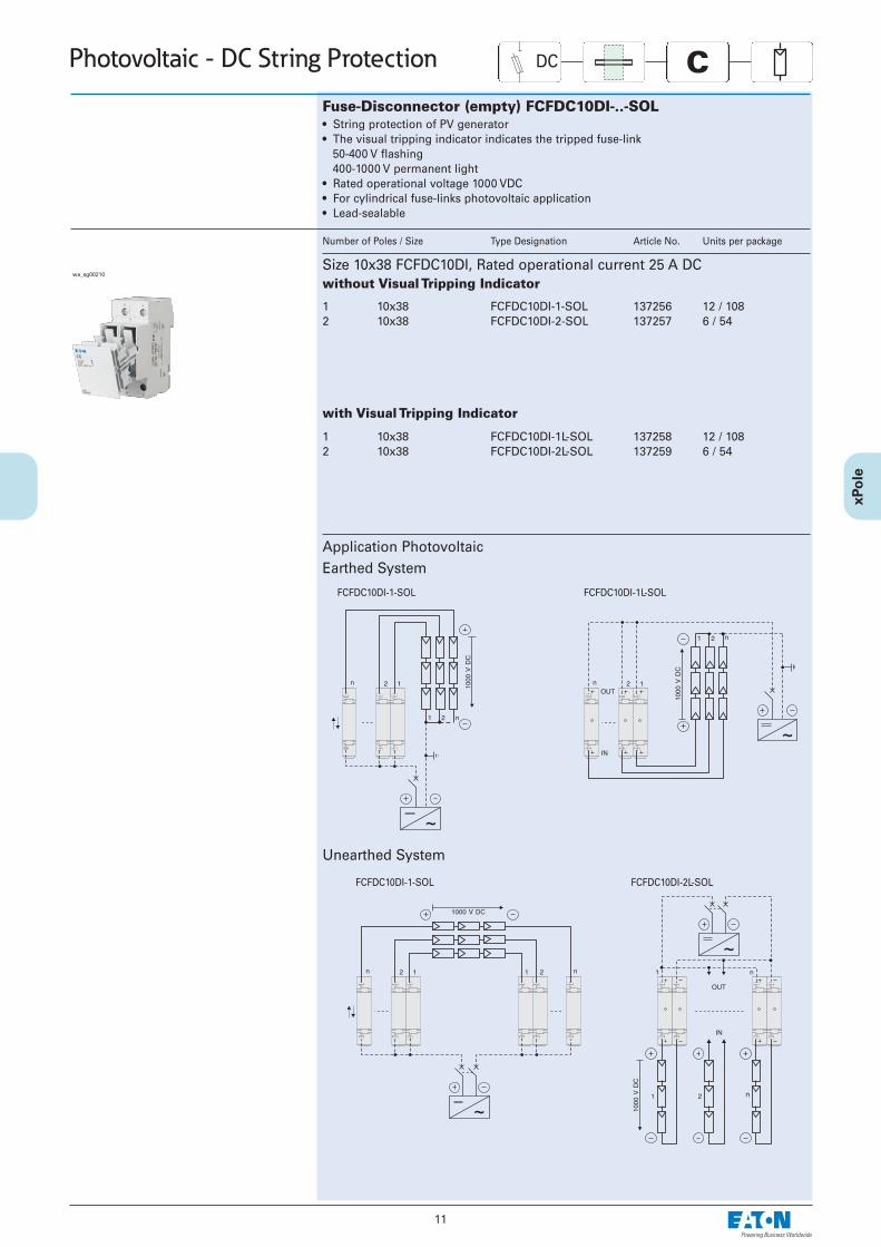
Fuse-Disconnector (empty) FCFDC10DI-..-SOL• String protection of PV generator• The visual tripping indicator indicates the tripped fuse-link
50-400 V flashing400-1000 V permanent light
• Rated operational voltage 1000 VDC• For cylindrical fuse-links photovoltaic application• Lead-sealable
Number of Poles / Size Type Designation Article No. Units per package
Size 10x38 FCFDC10DI, Rated operational current 25 A DCwithout Visual Tripping Indicator
1 10x382 10x38
FCFDC10DI-1-SOL 137256 12 / 108FCFDC10DI-2-SOL 137257 6 / 54
1 10x382 10x38
FCFDC10DI-1L-SOL 137258 12 / 108FCFDC10DI-2L-SOL 137259 6 / 54
with Visual Tripping Indicator
Application PhotovoltaicEarthed System
Unearthed System
FCFDC10DI-1-SOL FCFDC10DI-1L-SOL
FCFDC10DI-1-SOL FCFDC10DI-2L-SOL
wa_sg00210
12
Photovoltaic - DC String Protection CSize / Rated current / Rated voltage Type Designation Article No. Units per package
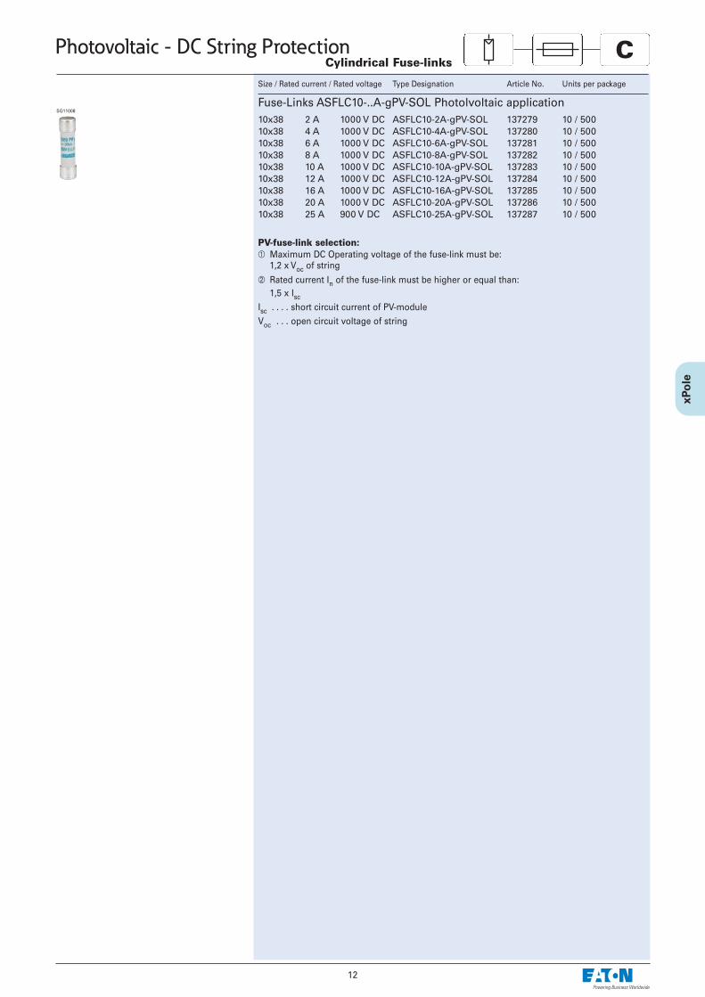
Fuse-Links ASFLC10-..A-gPV-SOL Photolvoltaic application10x38 2 A 1000 V DC10x38 4 A 1000 V DC10x38 6 A 1000 V DC10x38 8 A 1000 V DC10x38 10 A 1000 V DC10x38 12 A 1000 V DC10x38 16 A 1000 V DC10x38 20 A 1000 V DC10x38 25 A 900 V DC
ASFLC10-2A-gPV-SOL 137279 10 / 500ASFLC10-4A-gPV-SOL 137280 10 / 500ASFLC10-6A-gPV-SOL 137281 10 / 500ASFLC10-8A-gPV-SOL 137282 10 / 500ASFLC10-10A-gPV-SOL 137283 10 / 500ASFLC10-12A-gPV-SOL 137284 10 / 500ASFLC10-16A-gPV-SOL 137285 10 / 500ASFLC10-20A-gPV-SOL 137286 10 / 500ASFLC10-25A-gPV-SOL 137287 10 / 500
SG11008
Cylindrical Fuse-links
PV-fuse-link selection:À Maximum DC Operating voltage of the fuse-link must be:
1,2 x Voc of string
Á Rated current In of the fuse-link must be higher or equal than:1,5 x Isc
Isc . . . . short circuit current of PV-moduleVoc . . . open circuit voltage of string
13
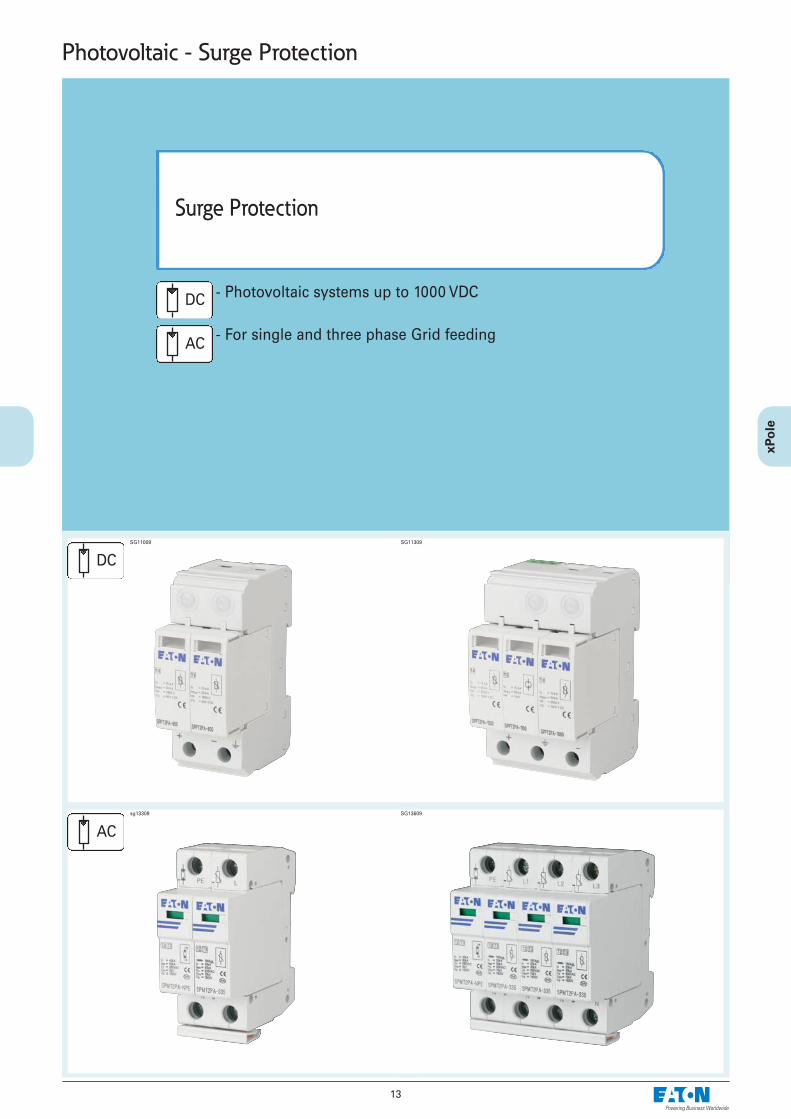
Photovoltaic - Surge Protection
- Photovoltaic systems up to 1000 VDC
- For single and three phase Grid feeding
Surge Protection
sg13309 SG13609
SG11009 SG11309
AC
DC
AC
DC
14
Photovoltaic - Surge Protection
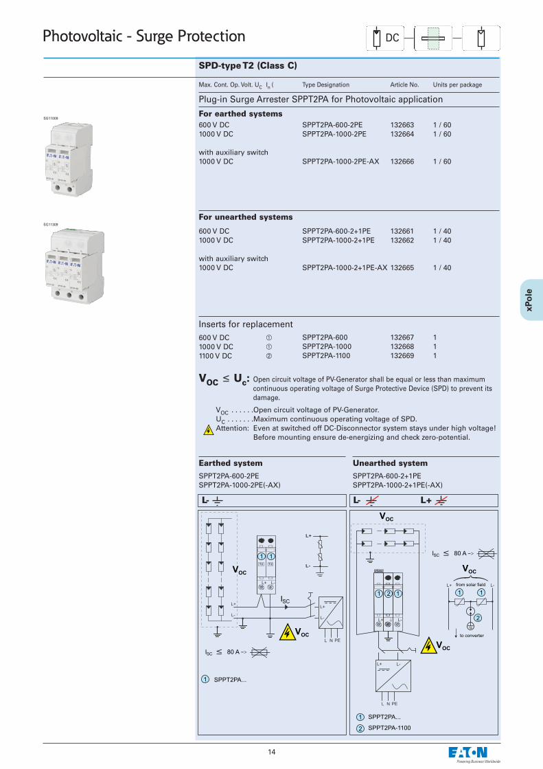
SPD-type T2 (Class C)
Max. Cont. Op. Volt. UC In ( Type Designation Article No. Units per package
600 V DC1000 V DC
with auxiliary switch1000 V DC
SPPT2PA-600-2PE 132663 1 / 60SPPT2PA-1000-2PE 132664 1 / 60
SPPT2PA-1000-2PE-AX 132666 1 / 60
For unearthed systems
600 V DC1000 V DC
with auxiliary switch1000 V DC
SPPT2PA-600-2+1PE 132661 1 / 40SPPT2PA-1000-2+1PE 132662 1 / 40
SPPT2PA-1000-2+1PE-AX 132665 1 / 40
Plug-in Surge Arrester SPPT2PA for Photovoltaic application
For earthed systems
SG11309
SG11009
600 V DC À1000 V DC À1100 V DC Á
SPPT2PA-600 132667 1SPPT2PA-1000 132668 1SPPT2PA-1100 132669 1
Inserts for replacement
Earthed system Unearthed systemSPPT2PA-600-2PESPPT2PA-1000-2PE(-AX)
SPPT2PA-600-2+1PESPPT2PA-1000-2+1PE(-AX)
L- L- L+
VOC ≤ Uc: Open circuit voltage of PV-Generator shall be equal or less than maximumcontinuous operating voltage of Surge Protective Device (SPD) to prevent itsdamage.
VOC . . . . . .Open circuit voltage of PV-Generator.UC . . . . . . .Maximum continuous operating voltage of SPD.Attention: Even at switched off DC-Disconnector system stays under high voltage!
Before mounting ensure de-energizing and check zero-potential.
DC
15
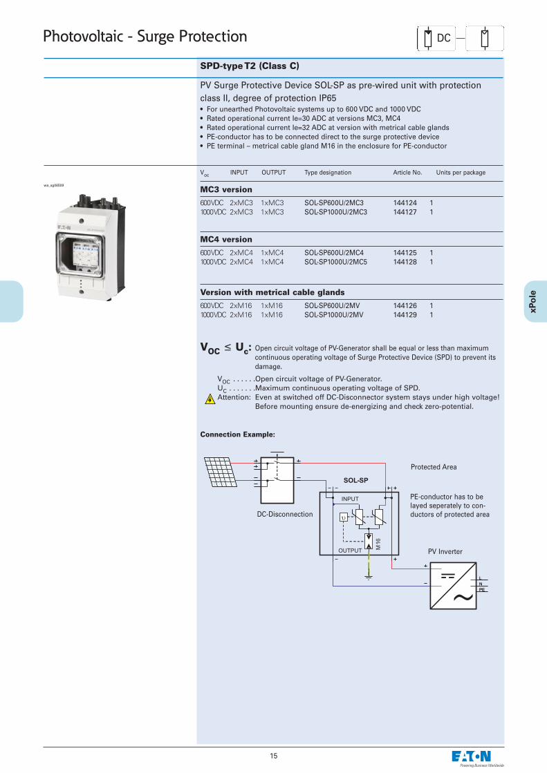
Photovoltaic - Surge Protection
PV Surge Protective Device SOL-SP as pre-wired unit with protectionclass II, degree of protection IP65• For unearthed Photovoltaic systems up to 600 VDC and 1000 VDC• Rated operational current Ie=30 ADC at versions MC3, MC4• Rated operational current Ie=32 ADC at version with metrical cable glands• PE-conductor has to be connected direct to the surge protective device• PE terminal – metrical cable gland M16 in the enclosure for PE-conductor
Voc INPUT OUTPUT Type designation Article No. Units per package
SPD-type T2 (Class C)
MC3 version
600 VDC 2xMC3 1xMC31000 VDC 2xMC3 1xMC3
SOL-SP600U/2MC3 144124 1SOL-SP1000U/2MC3 144127 1
MC4 version
600 VDC 2xMC4 1xMC41000 VDC 2xMC4 1xMC4
SOL-SP600U/2MC4 144125 1SOL-SP1000U/2MC5 144128 1
Version with metrical cable glands
600 VDC 2xM16 1xM161000 VDC 2xM16 1xM16
SOL-SP600U/2MV 144126 1SOL-SP1000U/2MV 144129 1
VOC ≤ Uc: Open circuit voltage of PV-Generator shall be equal or less than maximumcontinuous operating voltage of Surge Protective Device (SPD) to prevent itsdamage.
VOC . . . . . .Open circuit voltage of PV-Generator.UC . . . . . . .Maximum continuous operating voltage of SPD.Attention: Even at switched off DC-Disconnector system stays under high voltage!
Before mounting ensure de-energizing and check zero-potential.
Connection Example:
DC
DC-Disconnection
Protected Area
PV Inverter
PE-conductor has to belayed seperately to con-ductors of protected area
wa_sg06509
16
Photovoltaic - Surge Protection
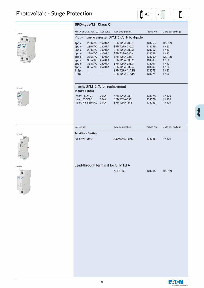
SPD-type T2 (Class C)
Max. Cont. Op. Volt. UC In (8/20)µs Type Designation Article No. Units per package
Description Type designation Article No. Units per package
Inserts SPMT2PA for replacementInsert 1-pole
Insert 280VAC 20kAInsert 335VAC 20kAInsert N-PE 260VAC 30kA
SPMT2PA-280 131778 4 / 120SPMT2PA-335 131779 4 / 120SPMT2PA-NPE 131783 4 / 120
Plug-in surge arrester SPMT2PA, 1- to 4-pole
1pole 280VAC 1x20kA2pole 280VAC 2x20kA3pole 280VAC 3x20kA4pole 280VAC 4x20kA1pole 335VAC 1x20kA2pole 335VAC 2x20kA3pole 335VAC 3x20kA4pole 335VAC 4x20kA1+1p – –3+1p – –
SPMT2PA-280/1 131755 12 / 120SPMT2PA-280/2 131756 1 / 60SPMT2PA-280/3 131757 1 / 40SPMT2PA-280/4 131758 1 / 30SPMT2PA-335/1 131759 12 / 120SPMT2PA-335/2 131760 1 / 60SPMT2PA-335/3 131761 1 / 40SPMT2PA-335/4 131762 1 / 30SPMT2PA-1+NPE 131773 1 / 60SPMT2PA-3+NPE 131774 1 / 30
Auxiliary Switch
sg13309
SG12809
SG13109
AC
Lead-through terminal for SPMT2PA
ASLTT-63 131784 12 / 120
for SPMT2PA ASAUXSC-SPM 131785 4 / 120
SG12909
17
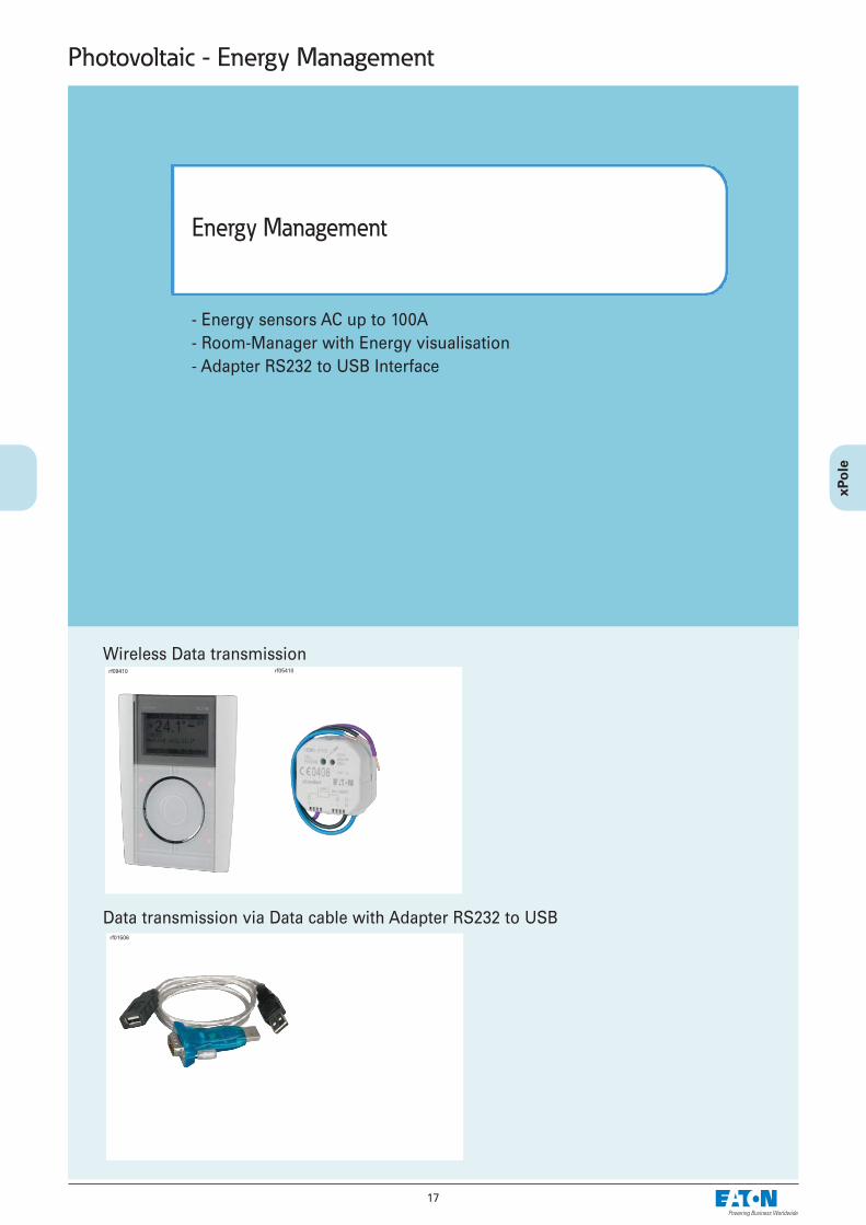
- Energy sensors AC up to 100A- Room-Manager with Energy visualisation- Adapter RS232 to USB Interface
Energy Management
Photovoltaic - Energy Management
Wireless Data transmission
Data transmission via Data cable with Adapter RS232 to USB
rf05410
rf01506
rf09410
18
Photovoltaic - RF System - Flush-mounted devices
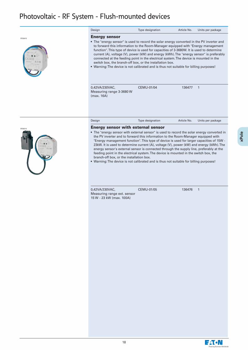
0,42VA/230VAC, Measuring range 3-3680 W(max. 16A)
CEMU-01/04 136477 1
Design Type designation Article No. Units per package
Energy sensor• The "energy sensor" is used to record the solar energy converted in the PV inverter and
to forward this information to the Room-Manager equipped with "Energy managementfunction". This type of device is used for capacities of 3-3680W. It is used to determinecurrent (A), voltage (V), power (kW) and energy (kWh). The "energy sensor" is preferablyconnected at the feeding point in the electrical system. The device is mounted in theswitch box, the branch-off box, or the installation box.
• Warning: The device is not calibrated and is thus not suitable for billing purposes!
0,42VA/230VAC, Measuring range ext. sensor15 W - 23 kW (max. 100A)
CEMU-01/05 136476 1
Design Type designation Article No. Units per package
Energy sensor with external sensor• The "energy sensor with external sensor" is used to record the solar energy converted in
the PV inverter and to forward this information to the Room-Manager equipped with"Energy management function". This type of device is used for larger capacities of 15W -23kW. It is used to determine current (A), voltage (V), power (kW) and energy (kWh). Theenergy sensor's external sensor is connected through the supply line, preferably at thefeeding point in the electrical system. The device is mounted in the switch box, thebranch-off box, or the installation box.
• Warning: The device is not calibrated and is thus not suitable for billing purposes!
RF05410
RF06510
19
Photovoltaic - RF System - Surface mounted devices
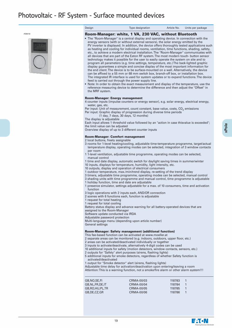
GB,NO,SE,FIGB,NL,FR,DE,ITGB,RO,HU,PL,TRGB,DE,CZ,GR
CRMA-00/03 118783 1CRMA-00/04 118784 1CRMA-00/05 118785 1CRMA-00/06 118786 1
Design Type designation Article No. Units per package
Room-Manager: white, 1 VA, 230 VAC, without Bluetooth• The "Room-Manager" is a central display and operating device. In connection with the
energy sensors (with or without external sensors), the solar energy emitted by the PV inverter is displayed. In addition, the device offers thoroughly tested applications such as heating and cooling for individual rooms, ventilation, time functions, shading, safety, etc., to achieve a modern electrical installation. The "Room-Manager" communicates with all devices that are part of the Eaton RF system. The most modern touch- button sensortechnology makes it possible for the user to easily operate the system on site and to program all parameters (e.g. time settings, temperature, etc.) The back-lighted graphic display guarantees a simple and concise display of the most important information for the end client. The device is to be surface-mounted on a wall. Alternatively, the device can be affixed to a 55 mm or 68 mm switch box, branch-off box, or installation box. The integrated IR interface is used for system updates or to expand functions. The device feed is carried out through the power supply line.
• Note: In order to obtain the exact measurement and display of the temperature, use thereference measuring device to determine the difference and then adjust the "Offset" inthe MRF system.
Room-Manager: Energy management4 counter inputs (impulse counters or energy sensor), e.g. solar energy, electrical energy,
water, gas, etc.Per input: Unit of measurement, count constant, base value, costs, CO2 emissionsPer input: Graphic display of progression during diverse time periods
(1 day, 7 days, 30 days, 12 months)The display is adjustableEach input allows 1 threshold value followed by an "action in case thisvalue is exceeded";the limit value can be adjustedOverview display of up to 3 different counter inputs
Room-Manager: Comfort management2 local buttons, freely assignable3 rooms for 1-level heating/cooling, adjustable time-temperature programme, target/actual
temperature display, operating modes can be selected, integration of 3 window contacts per room
1 1-level ventilation, adjustable time programme, operating modes can be selected, manual control
1 time and date display, automatic switch for daylight saving times in summer/winter10 inputs, displays for temperature, humidity, light intensity, etc.10 outputs, display and operation of electrical consumers1 outdoor temperature, max./min/trend display, re-setting of the trend display3 timers, adjustable time programme, operating modes can be selected, manual control3 shading units with time programme and manual control, time programme is adjustable1 holiday function, time and date are adjustable1 presence simulator, settings adjustable for a max. of 10 consumers, time and activation
function3 logic operations with 2 inputs each, AND/OR connection2 scenes with 6 functions each, function is adjustable1 request for total heating1 request for total coolingBattery status display and advance warning for all battery-operated devices that areassigned to the Room-ManagerSoftware update conducted via IRDAAdjustable password protectionMulti-language menu (depending upon article number)General settings
Room-Manager: Safety management (additional function)This fee-based function can be activated at www.moeller.at2 separate areas can be monitored (e.g. indoors, outdoors, upper floor, etc.)2 areas can be activated/deactivated individually or together3 inputs to activate/deactivate, alternatively 4-digit codes can be used10 additional inputs for safety (motion detectors, window contacts, sensors, etc.)2 outputs for "Safety" alert purposes (sirens, flashing lights)5 additional inputs for smoke detectors, regardless of whether Safety function is
activated/deactivated1 output for "Smoke detector" alert (sirens, flashing lights)Adjustable time delay for activation/deactivation upon entering/leaving a roomAttention: This is a warning function, not a smoke/fire alarm or other alarm system!!!
rf09410
20
Photovoltaic - Energy Management
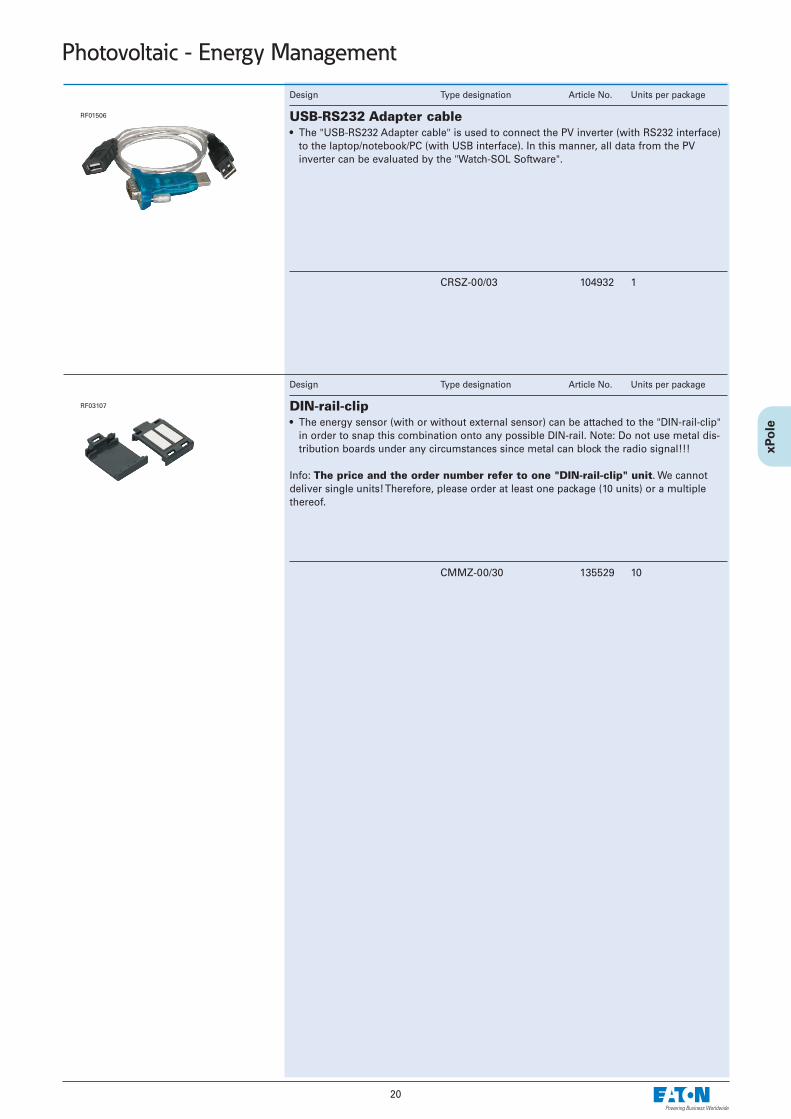
CRSZ-00/03 104932 1
Design Type designation Article No. Units per package
USB-RS232 Adapter cable• The "USB-RS232 Adapter cable" is used to connect the PV inverter (with RS232 interface)
to the laptop/notebook/PC (with USB interface). In this manner, all data from the PVinverter can be evaluated by the "Watch-SOL Software".
RF01506
CMMZ-00/30 135529 10
Design Type designation Article No. Units per package
DIN-rail-clip• The energy sensor (with or without external sensor) can be attached to the "DIN-rail-clip"
in order to snap this combination onto any possible DIN-rail. Note: Do not use metal dis-tribution boards under any circumstances since metal can block the radio signal!!!
Info: The price and the order number refer to one "DIN-rail-clip" unit. We cannotdeliver single units! Therefore, please order at least one package (10 units) or a multiplethereof.
RF03107


