1 Please fill out online course evaluation http://www.purdue.edu/eval Dr. Pyrak-Nolte and I would really appreciate your feedback THANKS! ANNOUNCEMENT • Final: Wednesday, December 14, 2016, 7 PM - 9 PM • Location: Elliot Hall of Music • Covers all readings, lectures, homework from Chapters 28.4 through 33 – Multiple choice • Practice exams on the course website and on CHIP • Bring your student ID card and your own 1-page (8-1/2” x 11”, both sides) crib sheet plus the original (or revised) crib sheets that you prepared for Exams 1 and 2 – Only a few equations will be given • The equation sheet that will be given with the exam is posted on the course homepage (“Equationsheet”) – It is your responsibility to create your own crib sheets
Transcript
1
Please fill out online course evaluation
http://www.purdue.edu/eval
Dr. Pyrak-Nolte and I would really appreciate your feedback
THANKS!
ANNOUNCEMENT • Final: Wednesday, December 14, 2016, 7 PM - 9 PM • Location: Elliot Hall of Music • Covers all readings, lectures, homework from
Chapters 28.4 through 33 – Multiple choice
• Practice exams on the course website and on CHIP • Bring your student ID card and your own 1-page
(8-1/2” x 11”, both sides) crib sheet plus the original (or revised) crib sheets that you prepared for Exams 1 and 2 – Only a few equations will be given
• The equation sheet that will be given with the exam is posted on the course homepage (“Equationsheet”)
– It is your responsibility to create your own crib sheets
2
LECTURE 27: Interference, Diffraction, Resolution
Interference Different Path Lengths
• The phase difference between two waves can change if the waves travel paths of different lengths
• Interference maxima
• Interference minima
d sinθm = mλm = order number = 0,1,2,...
d sinθm = m− 12
⎛
⎝⎜⎜⎜
⎞
⎠⎟⎟⎟λ
m = 1,2,3,...
3
Interference Different Path Lengths
I=4I0 cos2 δ
2δ= 2πd
λsinθ
Diffraction • Geometrical optics
– When length scales of an edge, obstacle, or aperture are >> than the light’s wavelength
• Light propagates as rays • Forms bright, sharp image and dark, sharp shadows
• Wave optics – When length scales of an edge, obstacle, or aperture are
comparable to the light’s wavelength • Waves spread out
– Can interfere constructively or destructively
= Diffraction • Interference patterns of light and dark fringes
– Geometric optics not a good approximation
4
Diffraction • Consider the case of light impinging on a small disk
We observe: – Bright spot in the center – Diffraction rings outside and inside the geometrical shadow area
• The bright spot at the center was predicted by Fresnel in 1818 and observed by Arago
Diffraction from a Disk
• Newton was a proponent of geometric optics (black lines)
• Fresnel believed in wave optics (red lines) – Waves that touch the top and bottom of the disk
travel the same distance to the center • Interfere constructively
Intensity
Cyl
indr
ical
ob
stac
le
Plane wave sc
reen
5
Diffraction from an Edge
Diffraction pattern
Plane wave
Obstacle
Diffraction from a Single Slit (screen far away)
• Consider a monochromatic wave incident on a narrow slit
• Geometrical optics predicts that the transmitted beam has the same cross section as the slit
• Experiments show that wave optics is correct – Central bright band that is wider than the width of the slit
– Alternating dark and bright fringes border the central bright band
6
Diffraction from a Single Slit
• Central bright fringe – Waves from all
points in the slit travel the same distance to reach the center
• Represent the slit as a number of point sources of equal amplitude
• Divide the slit into two • Pair a point from the upper half
with its partner in the lower half
a2
sinθ
(first minimum)
7
Diffraction from a Single Slit
asinθ1 =λ (location 1st min)
asinθ2 = 2λ (location 2nd min)
Locations of minima for single-slit diffraction:asinθm = mλ, m = 1,2,3,...
tanθm =
ym
L
Diffraction from a Single Slit
Incr
easi
ng a
pert
ure
Dependence of the central maximum on a:
a sinθ= mλ→ asinθ=λ
sinθ≈θ= λa
8
Question Two wavelengths, 650 and 430 nm, are used separately in a single-slit diffraction experiment. The figure shows the results as graphs of intensity, I, versus angle q for two diffraction patterns. If both wavelengths are then used simultaneously, what color will be seen in the combined diffraction pattern at angle D?
I
q D E
(A) Violet (B) Red
DEMO Diffraction from a Circular Aperture
• The diffraction pattern of a circular aperture of diameter d is similar to a single slit of width a
• Airy disk • Central bright spot
• About 85% of the power is in this area
• The dark fringes are found at:
sinθ1 = 1.22λd
sinθ2 = 2.23λd
sinθ3 = 3.24λd
9
• The bright fringes are at:
• The Airy disk limits the resolvability of nearby objects
Diffraction from a Circular Aperture
Image of two nearby binary stars but diffraction patterns overlap
sinθ1 = 1.63λd
sinθ2 = 2.68λd
sinθ3 = 3.70λd
Rayleigh Criterion When 1.22C d
≈
1
2
10
Maximum Falls on Minimum • The minimum angular separation αc of two marginally
resolvable points – Maximum of the diffraction pattern from one falls on the first
minimum of the diffraction pattern of the other
• The first minimum is at αC ≈1.22λ
d
Cen
tral A
xis
Rayleigh Criterion • The minimum angular separation αc of two marginally
resolvable points – Maximum of the diffraction pattern from one falls on the first
minimum of the diffraction pattern of the other
• The first minimum is at
• Therefore
αC ≈1.22λ
d
αC = θ=
sin−1 1.22λd
⎛
⎝⎜⎜⎜
⎞
⎠⎟⎟⎟≈1.22λ
d
Not resolved Resolved Barely resolved
11
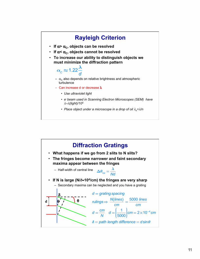
Rayleigh Criterion • If α> αC, objects can be resolved • If α< αC, objects cannot be resolved • To increase our ability to distinguish objects we
must minimize the diffraction pattern
– αC also depends on relative brightness and atmospheric turbulence
– Can increase d or decrease λ
• Use ultraviolet light
• e- beam used in Scanning Electron Microscopes (SEM) have λ≈λ(light)/105
• Place object under a microscope in a drop of oil λo=λ/n
αC ≈1.22λ
d
Diffraction Gratings • What happens if we go from 2 slits to N slits? • The fringes become narrower and faint secondary
maxima appear between the fringes – Half-width of central line
• If N is large (N/ℓ≈104/cm) the fringes are very sharp – Secondary maxima can be neglected and you have a grating
d δ
θ θ
d = gratingspacing
rulings⇒ N(lines)cm
= 5000 linescm
d = cmN
d = 15000⎛
⎝⎜⎜⎜
⎞
⎠⎟⎟⎟cm = 2×10⁻⁴cm
δ= path length difference = d sinθ
Δθhw = λ
Nd
12
DEMO Diffraction Gratings
• Sharp bright fringes occur if
– where m is the order of the maxima • Gratings are used to measure λ
– by detecting maxima of the diffraction pattern with m=1,2,…
• Resolving power
δ= d sinθ= mλ m = 0,1,2
sinθ= mλ
d
R = λ
Δλ= mN
Chose theta (hence m) and d, solve for lambda
In demo: wavelength is fixed, d decreases as N increases…so spacing between fringes increases…illumination region from laser is constant
Diffraction Gratings • For a given
wavelength and d, if N increases the half-width decreases