Page 1
10th EPRI Conf, TLH, Oct 11, 2011, talk #2, BEST, A.Usoskin
Physical principles and applications of inductive HTS shielded fault current limiting devices with suppressed cryogenic losses
This project is supported within Bruker HTS in part by the German Federal Ministry of Economics and Technology, BMWi, projects no. 0327456 and 03ET1003.
Alexander Usoskin, Alexander Rutt, Tom Withnell, Klaus Schlenga [BEST/BHTS]Mischa Steurer, Sastry Pamidi, Lukas Graber, Jozef Kvitkovic, Tim Chiocchio [FSU/CAPS]
For more details on iSFCL visit our talk #8 to be given by Alexander Henning tomorrow
Page 2
10th EPRI Conf, TLH, Oct 11, 2011, talk #2, BEST, A.Usoskin
2
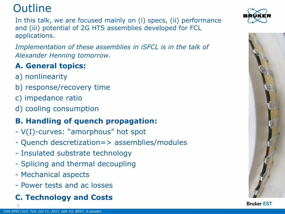
OutlineIn this talk, we are focused mainly on (i) specs, (ii) performance and (iii) potential of 2G HTS assemblies developed for FCL applications.
Implementation of these assemblies in iSFCL is in the talk of
Alexander Henning tomorrow.
A. General topics:
a) nonlinearity
b) response/recovery time
c) impedance ratio
d) cooling consumption
B. Handling of quench propagation:
- V(I)-curves: “amorphous” hot spot
- Quench descretization=> assemblies/modules
- Insulated substrate technology
- Splicing and thermal decoupling
- Mechanical aspects
- Power tests and ac losses
C. Technology and Costs
Page 3
10th EPRI Conf, TLH, Oct 11, 2011, talk #2, BEST, A.Usoskin
BHTS coated conductors: basic architecture
3
Cu-envelope, 20 µm SS substrate (50-100 µm)
YSZ buffer (~1.5 µm)
CeO2 buffer (~0.05 µm)
YBCO (1-3 µm)Ag/Au protection layer (0.1-3 µm)
Cu-envelope, 20 µm SS substrate (50-100 µm)
YSZ buffer (~1.5 µm)
CeO2 buffer (~0.05 µm)
YBCO (1-3 µm)Ag/Au protection layer (0.1-3 µm)
+ Low cost PLD+ Highest currents
+ Stable & robustsolution
+ Low cost substrate
Page 4
10th EPRI Conf, TLH, Oct 11, 2011, talk #2, BEST, A.Usoskin
Inductive shielded and resistive SFCL
SUPERPOLI FCL-5.5-50 module based on YBCO-
coated stainless steel tubes and Au shunt layer.
Nominal (non-limited) current 2 500 A (ampl.)
Nominal power losses ~ 0.1 W
Fault current, max. 50 000 A (ampl.)
Peak power at fault current: 150 000 W
55 mm
500 mm
Page 5
10th EPRI Conf, TLH, Oct 11, 2011, talk #2, BEST, A.Usoskin
Bruker HTS CC Tapes and Modules
(a)40 mm wide CC tapes.
(b, c) SFCL modules based on these tapes.
(d, e) Modules manufactured from 4 mm CC tapes.
Page 6
10th EPRI Conf, TLH, Oct 11, 2011, talk #2, BEST, A.Usoskin
Resistive Inductive With Saturable Core
Uac/dc Uac Uac
Im=f(Io)
IoIo
SFCL spectrum
Page 7
10th EPRI Conf, TLH, Oct 11, 2011, talk #2, BEST, A.Usoskin
Sequential and avalanche quench
current
voltage
current
voltage
rSFCL:“sequential” quench
iSFCL:“avalanche” quench
i1q
i2q
i3q
iNq
i1q i2q i3q iNq
iq, tot = iq min iq, tot = iq,j j
Page 8
10th EPRI Conf, TLH, Oct 11, 2011, talk #2, BEST, A.Usoskin
LN2 consumption in “stay-alone” modus
rSFCL: iSFCL:
40 MVA design in both r- and i-SFCLs (preliminary estimates)
74 m3 per ½ year 4.5 m3 per ½ year
tanktank
Cryotank
Cryo-design:
Cryocooler 850 W of cooling power 50 W of cooling power
Page 9
10th EPRI Conf, TLH, Oct 11, 2011, talk #2, BEST, A.Usoskin
Mechanisms of quench development in wide HTS Coated Conductors
2011, May 039 Board Meeting, Alzenau
Page 10
10th EPRI Conf, TLH, Oct 11, 2011, talk #2, BEST, A.Usoskin
I(V) curve: iSFCL, Cu losses are subtracted
Test SU240b cu100trns, 11x7CC-mod
0
1000
2000
3000
4000
5000
6000
7000
0 10 20 30 40 50 60 70 80 90 100
voltage 1, V
cu
rre
nt
2, p
ros
p. c
urr
en
t 1
, A
3800A Oscill.
Z1(at 3000A)=0.25 V/30 A= 8.3 mOhms => ΔU = 0.8 V at 100A
Uac
voltage, V
curr
ent,
A
Page 11
10th EPRI Conf, TLH, Oct 11, 2011, talk #2, BEST, A.Usoskin
iSFCL: I(V) curves
we call this “amorphous” quench because the hot-spot may be arbitrary shaped.
0
200
400
600
800
1000
0 20 40 60
Voltage (V)
Cu
rren
t (A
)
0,2
1
0,6
2
3
A B C D
0,4
Page 12
10th EPRI Conf, TLH, Oct 11, 2011, talk #2, BEST, A.Usoskin
Z(I) curves
0
2
4
6
0 2 4 6
Current (kA)
Resis
tan
ce (
mO
hm
s) 1 2
3
IS-SFCL
IS-SFCL
R-SFCL
Imp
ed
an
ce
Page 13
10th EPRI Conf, TLH, Oct 11, 2011, talk #2, BEST, A.Usoskin
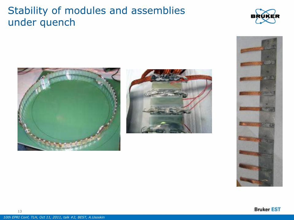
Stability of modules and assemblies under quench
13
Page 14
10th EPRI Conf, TLH, Oct 11, 2011, talk #2, BEST, A.Usoskin
0 0.2 0.4 0.6 0.8 1 1.20.01
0.1
1
10
100
1 103
1 104
1 105
1 106
1 107
1 108
1 109
Lcr( ),0.004 L
Lcr( ),0.002 L
L
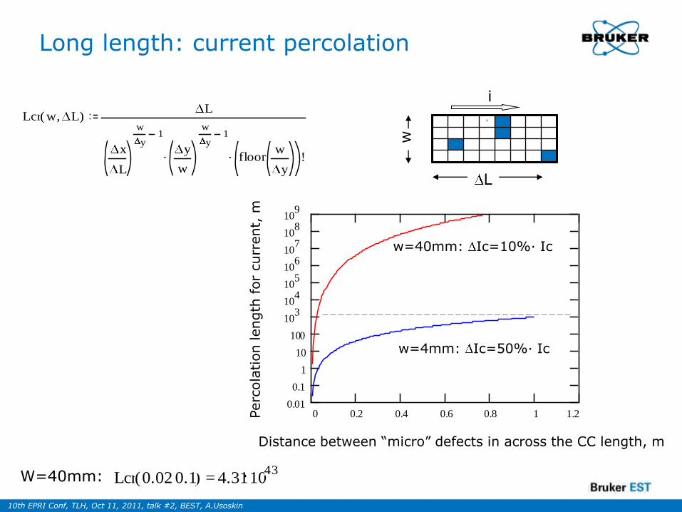
w=4mm: Ic=50%· Ic
w=40mm: Ic=10%· IcPerc
ola
tion length
for
curr
ent,
m
Distance between “micro” defects in across the CC length, m
Lcr( ),w LL
..x
L
w
y1
y
w
w
y1
!floorw
y
X
L
w
i
Long length: current percolation
=Lcr( ),0.02 0.1 4.311043W=40mm:
Page 15
10th EPRI Conf, TLH, Oct 11, 2011, talk #2, BEST, A.Usoskin
Quench stability and quench “discretization”: CC tape-shunt assemblies for SFCL
15
RHTS+protect=3-5 Ohms/m
Rsusbstr=0.25 Ohms/m
HTS layer
Substrate (stainless steel)
Insulated metallic substrate
HTS layer
External shunt tape (stainless steel)
Power dissipation (in current driven modus)= 30-100 kW=> overheating within 100 ms
40 mm wide SFCL tapes:
The same power dissipation now occurs in external shunt=> fault duration may be extended to almost 500 ms
current
current
Cu bridges
current
voltage
Cu bridges
<25 mm wide CC tapes seems to be not feasible in such application: # of bridges becomes too high
Page 16
10th EPRI Conf, TLH, Oct 11, 2011, talk #2, BEST, A.Usoskin
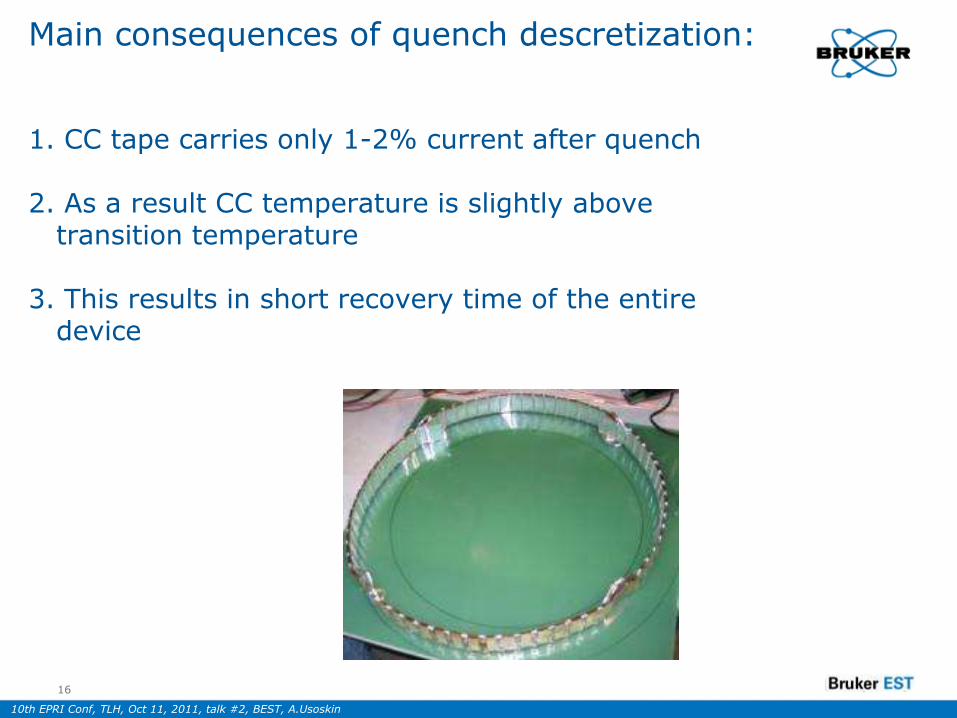
Main consequences of quench descretization:
1. CC tape carries only 1-2% current after quench
2. As a result CC temperature is slightly abovetransition temperature
3. This results in short recovery time of the entiredevice
16
Page 17
10th EPRI Conf, TLH, Oct 11, 2011, talk #2, BEST, A.Usoskin
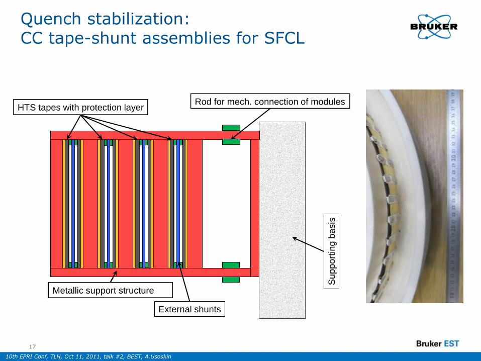
Quench stabilization: CC tape-shunt assemblies for SFCL
17
HTS tapes with protection layer
Metallic support structure
Rod for mech. connection of modules
External shunts
Sup
po
rtin
gb
asis
Page 18
10th EPRI Conf, TLH, Oct 11, 2011, talk #2, BEST, A.Usoskin
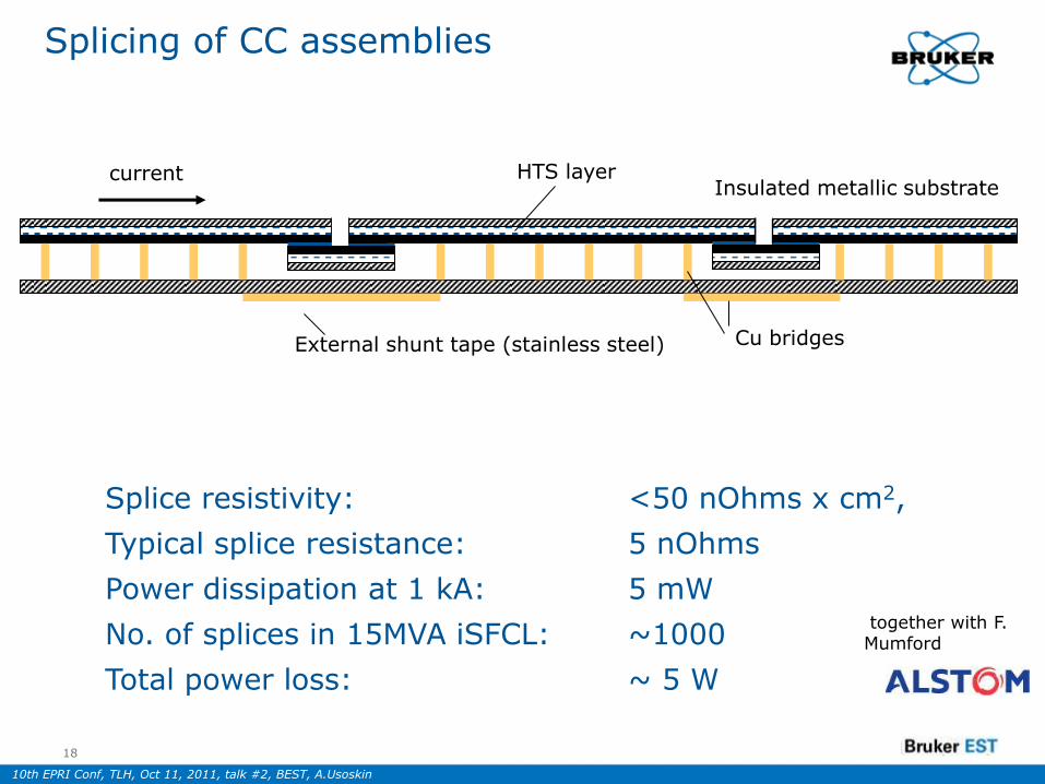
Splicing of CC assemblies
18
Insulated metallic substrate HTS layer
External shunt tape (stainless steel)
Splice resistivity: <50 nOhms x cm2,
Typical splice resistance: 5 nOhms
Power dissipation at 1 kA: 5 mW
No. of splices in 15MVA iSFCL: ~1000
Total power loss: ~ 5 W
current
Cu bridges
together with F. Mumford
Page 19
10th EPRI Conf, TLH, Oct 11, 2011, talk #2, BEST, A.Usoskin
Quench stability: Critical length of HTS tape (BHTS+Alstom)
19
Insulated metallic substrate HTS layer
External shunt tape (stainless steel)
Breakdown voltage: ~100V
may be doubled via central bridge
current
Cu bridges
together with F. Mumford
Page 20
10th EPRI Conf, TLH, Oct 11, 2011, talk #2, BEST, A.Usoskin
Quench stability: critical length of HTS tape (BHTS+Alstom)
20
Insulated metallic substrate HTS layer
External shunt tape (stainless steel)
current
Cu bridges
together with F. Mumford
Page 21
10th EPRI Conf, TLH, Oct 11, 2011, talk #2, BEST, A.Usoskin
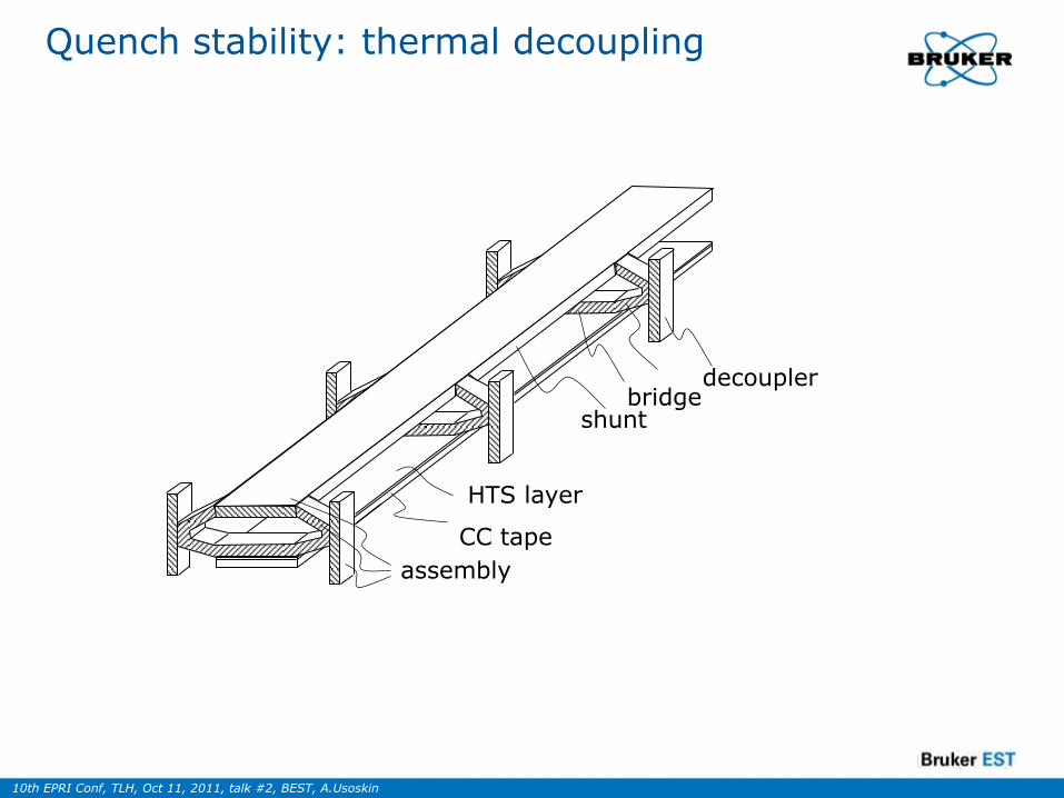
Quench stability: thermal decoupling
52
53
54
5555a
56, 57
51
shuntbridge
decoupler
CC tape
HTS layer
assembly
Page 22
10th EPRI Conf, TLH, Oct 11, 2011, talk #2, BEST, A.Usoskin
Mechanical aspects
22
Page 23
10th EPRI Conf, TLH, Oct 11, 2011, talk #2, BEST, A.Usoskin
Quench test
23
Iq=890 A
Il=480 A
Uac
Page 24
10th EPRI Conf, TLH, Oct 11, 2011, talk #2, BEST, A.Usoskin
Over-current test
24
Ipeak=1200 A, Upeak=9,0 V
Emax=4.5 V peak/cm-1
Iq=900 A
Il=480 A
No degradation !
Page 25
10th EPRI Conf, TLH, Oct 11, 2011, talk #2, BEST, A.Usoskin
Over-current test
25
At Ipeak=1200 A
Upeak=9,0 V
Iq=900 A
Il=480 AThere is no
degradation after 2000
repeated quenches:
Page 26
10th EPRI Conf, TLH, Oct 11, 2011, talk #2, BEST, A.Usoskin
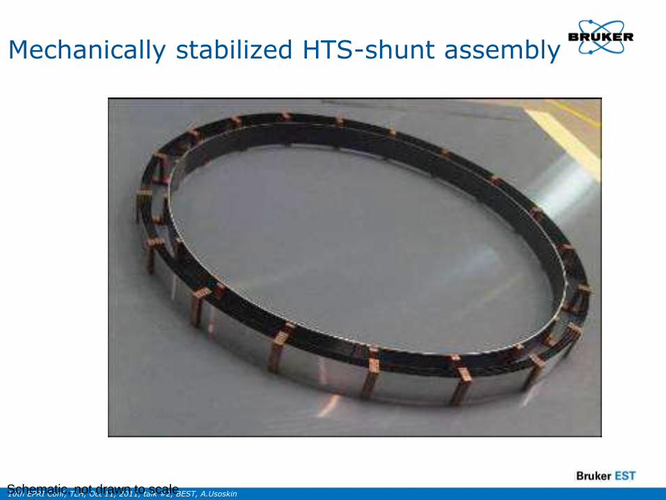
Mechanically stabilized HTS-shunt assembly
Schematic, not drawn to scale
Page 27
10th EPRI Conf, TLH, Oct 11, 2011, talk #2, BEST, A.Usoskin
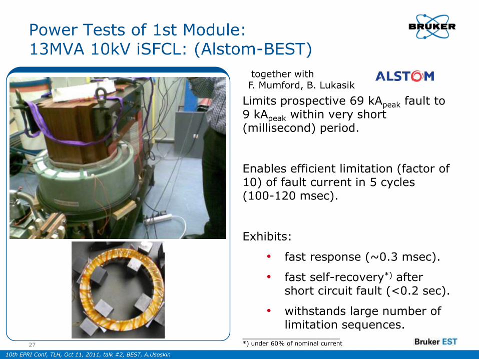
Power Tests of 1st Module: 13MVA 10kV iSFCL: (Alstom-BEST)
Limits prospective 69 kApeak fault to 9 kApeak within very short (millisecond) period.
Enables efficient limitation (factor of 10) of fault current in 5 cycles (100-120 msec).
Exhibits:
• fast response (~0.3 msec).
• fast self-recovery*) after short circuit fault (<0.2 sec).
• withstands large number of limitation sequences.
_____________________*) under 60% of nominal current27
together with F. Mumford, B. Lukasik
Page 28
10th EPRI Conf, TLH, Oct 11, 2011, talk #2, BEST, A.Usoskin
Areva – Bruker – Stadtwerke Augsburg Verbundvorhaben „iSFCL“
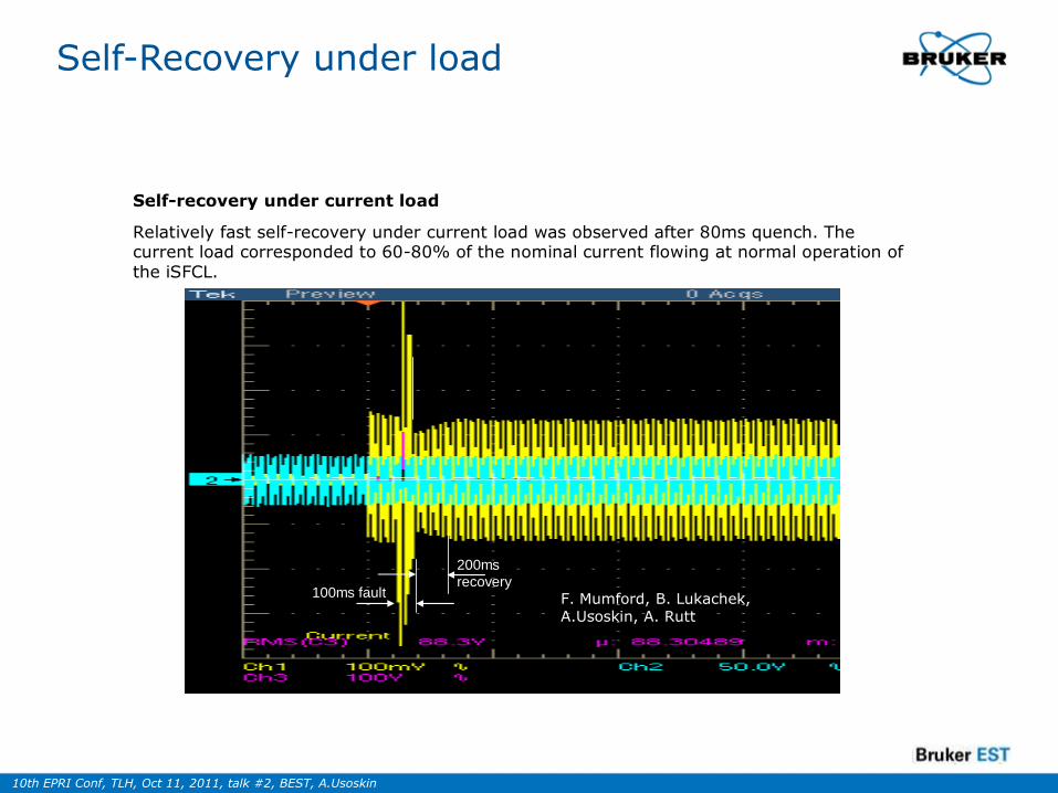
Self-recovery under current load
Relatively fast self-recovery under current load was observed after 80ms quench. The current load corresponded to 60-80% of the nominal current flowing at normal operation of the iSFCL.
Bruker ASC & HTS
100ms fault
200ms
recovery
F. Mumford, B. Lukachek,A.Usoskin, A. Rutt
Self-Recovery under load
Page 29
10th EPRI Conf, TLH, Oct 11, 2011, talk #2, BEST, A.Usoskin
Technolgy of Wide HTS Coated Conductors
2011, May 0329 Board Meeting, Alzenau
Page 30
10th EPRI Conf, TLH, Oct 11, 2011, talk #2, BEST, A.Usoskin
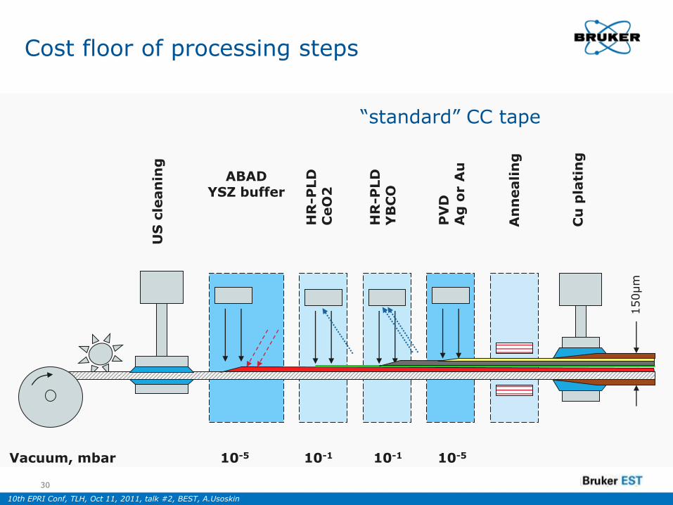
US
cle
an
ing
ABAD YSZ buffer
HR
-PLD
CeO
2
HR
-PLD
YB
CO
PV
DA
g o
r A
u
An
neali
ng
Cu
pla
tin
g
150µm
Vacuum, mbar 10-5 10-1 10-1 10-5
Cost floor of processing steps
30
“standard” CC tape
Page 31
10th EPRI Conf, TLH, Oct 11, 2011, talk #2, BEST, A.Usoskin
ABAD machine
2011, May 0331 Board Meeting, Alzenau
Page 32
10th EPRI Conf, TLH, Oct 11, 2011, talk #2, BEST, A.Usoskin
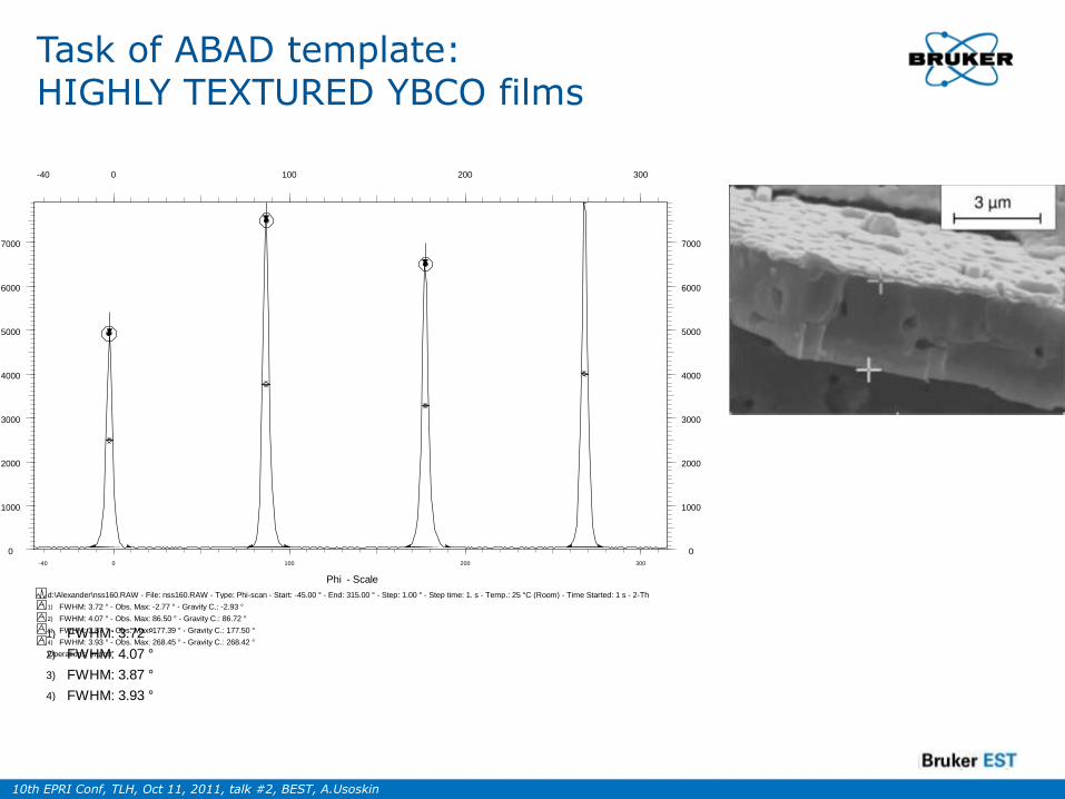
Task of ABAD template: HIGHLY TEXTURED YBCO films
NSS 160
Operations: Import
4)
3)
2)
1)
d:\Alexander\nss160.RAW - File: nss160.RAW - Type: Phi-scan - Start: -45.00 ° - End: 315.00 ° - Step: 1.00 ° - Step time: 1. s - Temp.: 25 °C (Room) - Time Started: 1 s - 2-Th
FWHM: 3.93 ° - Obs. Max: 268.45 ° - Gravity C.: 268.42 °
FWHM: 3.87 ° - Obs. Max: 177.39 ° - Gravity C.: 177.50 °
FWHM: 4.07 ° - Obs. Max: 86.50 ° - Gravity C.: 86.72 °
FWHM: 3.72 ° - Obs. Max: -2.77 ° - Gravity C.: -2.93 °
0
1000
2000
3000
4000
5000
6000
7000
0
1000
2000
3000
4000
5000
6000
7000
-40 0 100 200 300
Phi - Scale
-40 0 100 200 300
Page 33
10th EPRI Conf, TLH, Oct 11, 2011, talk #2, BEST, A.Usoskin
CC/module production: HR-PLD
6 beam HR-PLD
6B-PLD machine with deposition area of 0.13m2
Depositionchamber
Optical system
Page 34
10th EPRI Conf, TLH, Oct 11, 2011, talk #2, BEST, A.Usoskin
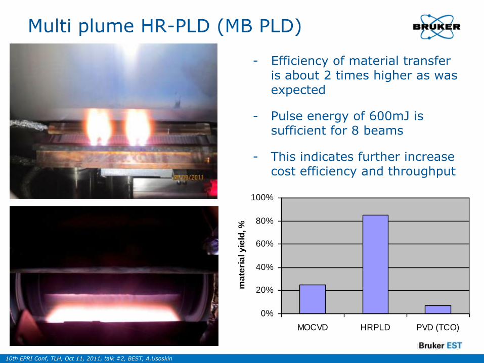
Multi plume HR-PLD (MB PLD)
0%
20%
40%
60%
80%
100%
MOCVD HRPLD PVD (TCO)
ma
teri
al y
ield
, %
- Efficiency of material transfer is about 2 times higher as was expected
- Pulse energy of 600mJ is sufficient for 8 beams
- This indicates further increase cost efficiency and throughput
Page 35
10th EPRI Conf, TLH, Oct 11, 2011, talk #2, BEST, A.Usoskin
19.10.201135
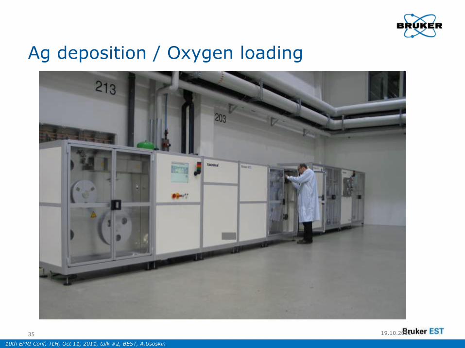
Ag deposition / Oxygen loading
Page 36
10th EPRI Conf, TLH, Oct 11, 2011, talk #2, BEST, A.Usoskin
2011, May 0336 Board Meeting, Alzenau
Cu plating
Page 37
10th EPRI Conf, TLH, Oct 11, 2011, talk #2, BEST, A.Usoskin
2011, May 0337 Board Meeting, Alzenau
Ic Tape Test in Continuous Modus
Page 38
10th EPRI Conf, TLH, Oct 11, 2011, talk #2, BEST, A.Usoskin
Mechanical Stability
• Good “mechanics” of stainless steel substrate (650 MPa of yield strength) is translated to the entire CC tape:
- tensile stress, max.: 650 MPa
- bending radius, min.: 6mm
- tape torsion (4mm wide CC): 30° per cm at 40N axial load
• Cost-effective stainless steel substrate(reduces costs by 2-3 Euro/kAm)
Page 39
10th EPRI Conf, TLH, Oct 11, 2011, talk #2, BEST, A.Usoskin
0
500
1000
1500
2000
2500
0 5 10 15 20 25 30
B [T]
Ic [
A]
B||c
B||a,b
BHTS tape
t=1.8µm; w =4mm
BHTS
KIT measurements
t=1.8µm; w =4mm
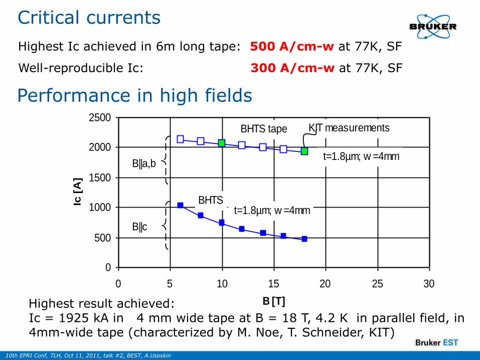
Highest result achieved: Ic = 1925 kA in 4 mm wide tape at B = 18 T, 4.2 K in parallel field, in 4mm-wide tape (characterized by M. Noe, T. Schneider, KIT)
Performance in high fields
Critical currents
Highest Ic achieved in 6m long tape: 500 A/cm-w at 77K, SF
Well-reproducible Ic: 300 A/cm-w at 77K, SF
Page 40
10th EPRI Conf, TLH, Oct 11, 2011, talk #2, BEST, A.Usoskin
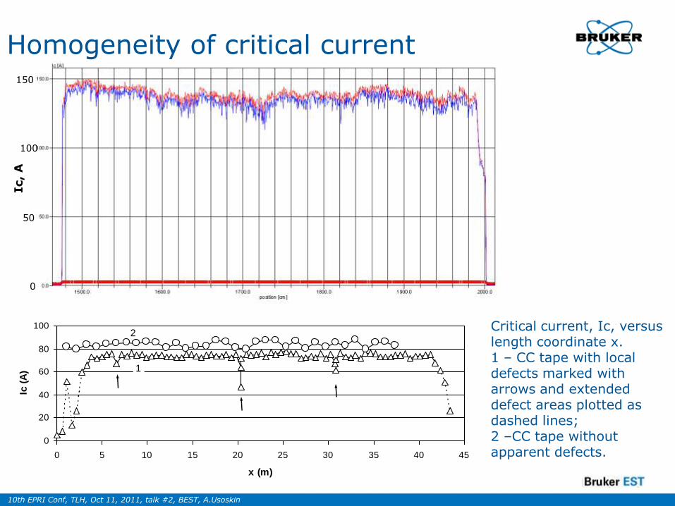
Homogeneity of critical current 150
100
50
0
Ic, A
0
20
40
60
80
100
0 5 10 15 20 25 30 35 40 45
x (m)
Ic (
A) 1
2Critical current, Ic, versus length coordinate x. 1 – CC tape with local defects marked with arrows and extended defect areas plotted as dashed lines; 2 –CC tape without apparent defects.
Page 41
10th EPRI Conf, TLH, Oct 11, 2011, talk #2, BEST, A.Usoskin
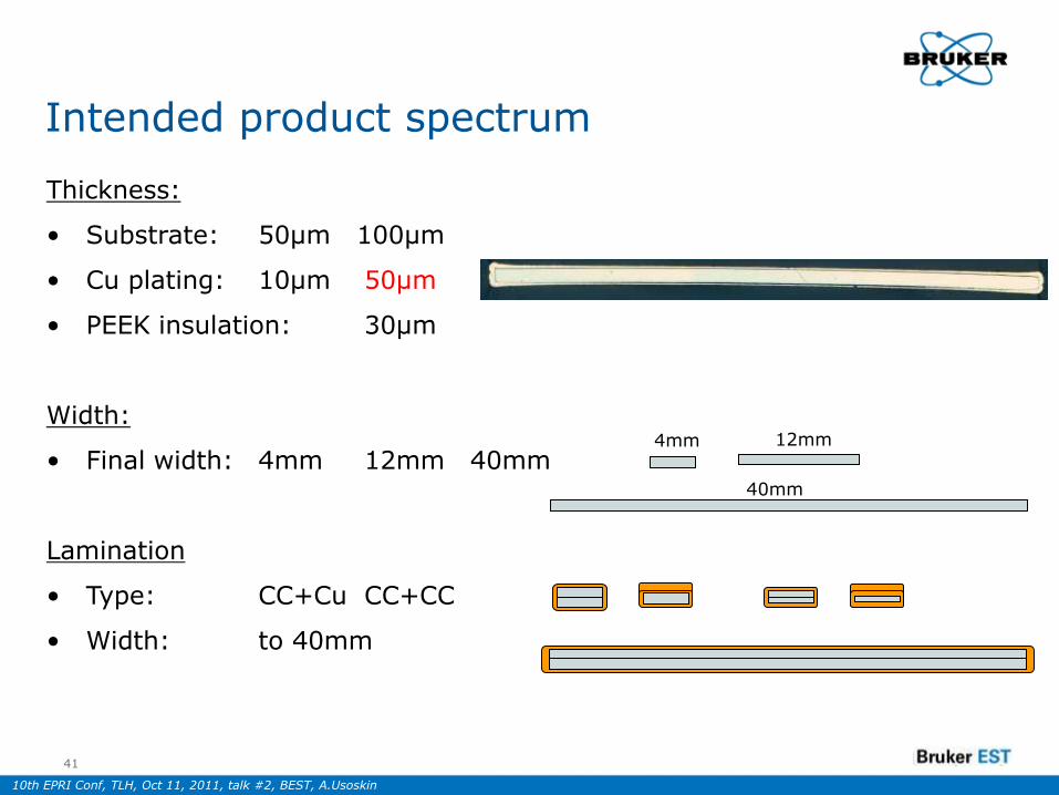
Intended product spectrum
Thickness:
• Substrate: 50µm 100µm
• Cu plating: 10µm 50µm
• PEEK insulation: 30µm
Width:
• Final width: 4mm 12mm 40mm
Lamination
• Type: CC+Cu CC+CC
• Width: to 40mm
4mm 12mm
40mm
41
Page 42
10th EPRI Conf, TLH, Oct 11, 2011, talk #2, BEST, A.Usoskin
The 800 m length of HTS coated conductors (Bruker-HTS) assembled into “double tape” (Ic>80A=>125A)[SUPER3C]
Page 43
10th EPRI Conf, TLH, Oct 11, 2011, talk #2, BEST, A.Usoskin
SUPER 3C – First European CC Cable Project
10/19/2011
As of March 2010:
Successful test of 30-meter long cable
based on PLD grown YBCO tapes.
YBCO (~1 µm)
YSZ Buffer (~1.5 µm)
SS-Substrate (100 µm), non-magnetic
CeO2 Buffer (~0.05 µm)
Au Protective/stabilizing layer (~0.2 µm)
Cu Shunt layer (~20 µm)
YBCO (~1 µm)
YSZ Buffer (~1.5 µm)
SS-Substrate (100 µm), non-magnetic
CeO2 Buffer (~0.05 µm)
Au Protective/stabilizing layer (~0.2 µm)
Cu Shunt layer (~20 µm)
YBCO (~1 µm)
YSZ Buffer (~1.5 µm)
SS-Substrate (100 µm), non-magnetic
CeO2 Buffer (~0.05 µm)
Au Protective/stabilizing layer (~0.2 µm)
Cu Shunt layer (~20 µm)
Nexans
Page 44
10th EPRI Conf, TLH, Oct 11, 2011, talk #2, BEST, A.Usoskin
Cost cake
CC processing steps: cost floor in % per kAm
64%
2%
17%
7%
3%5% 3%
Polishing
ABAD
PLD CeO2
PLD HTS
Protection layer
Annealing
Plating
ABAD
HR-PLD
Page 45
10th EPRI Conf, TLH, Oct 11, 2011, talk #2, BEST, A.Usoskin
Summary
45
- Quench descretization (QD) technique allows to manufacture FCL assemblies and modules with short response/recovery time (0.3ms/10ms)
- QD assemblies are based on wide (30-60mm) HTS coated conductor.
- The assemblies allow high (>10) impedance ratio as well as low cooling consumption
- Low ac losses in ring formed stacks are recently found
- Stay-alone operation of SFCL based on QD modules seems to be possible because of low cryo-loss.
- 2G production technology will allow cost efficient FCL solutions
Page 46
10th EPRI Conf, TLH, Oct 11, 2011, talk #2, BEST, A.Usoskin
46