Generation of Orbital Angular Momentum by a Point Defect in Photonic Crystals
Menglin L. N. Chen,1 Li Jun Jiang,1 and Wei E. I. Sha2,*
1Electromagnetics and Optics Laboratory, Department of Electrical and Electronic Engineering, The Universityof Hong Kong, Hong Kong, Hong Kong
2The Innovative Institute of Electromagnetic Information and Electronic Integration, College of InformationScience and Electronic Engineering, Zhejiang University, Hangzhou 310027, P. R. China
(Received 3 May 2017; revised manuscript received 6 August 2017; published 31 July 2018)
As an attractive degree of freedom in electromagnetic (EM) waves, the orbital angular momentum(OAM) enables infinite communication channels for both classical and quantum communications. Theexploration of OAM generation inspires various designs involving spiral phase plates, antenna arrays,metasurfaces, and computer-generated holograms. In this work, we theoretically and experimentallydemonstrate an approach to producing OAM carrying EM waves by a point defect in three-dimensional(3D) photonic crystals (PCs). Simultaneous excitation of two vibrational-defect states with an elaboratelyengineered phase retardation generates a rotational state carrying OAM. Through converting guided wavesin a line defect to localized waves in a point defect and then to radiated vortex waves in free space, thelowest four OAM-mode emitters, i.e., OAM indices of ±1 and ±2, are successfully realized. This workoffers a physical mechanism to generate OAM by PCs, especially when the OAM generation is to beintegrated with other designs.
DOI: 10.1103/PhysRevApplied.10.014034
I. INTRODUCTION
Electromagnetic (EM) waves carry both linear andangular momenta. Recently, the angular momentum hasbeen attracting much attention due to the extra degreesof freedom introduced into EM waves. It is well knownthat circularly polarized waves carry spin angular momen-tum (SAM), which characterizes the spin feature ofa photon. Unlike the SAM, orbital angular momen-tum (OAM) manifests the orbital rotation of photon.It describes structured waves possessing a helical wavefront. The number of twists in the helical wave frontidentifies each OAM state. Therefore, OAM-carryingwaves cause distinctive phase structures and allow forpromising applications, ranging from classical to quantumregimes [1–8].
Since OAM is associated with the spatially variant phasefactor, eilφ (where φ is the azimuthal angle and l is theOAM index) [9], a great many designs that manipulatethe spatial phase have been proposed for OAM genera-tion, such as spiral phase plates (SPPs) [10–12], metasur-faces [13–18], computer-generated holograms [19,20], andother novel prototypes [21]. Although Maxwell’s equa-tions govern the behavior of EM waves from microwaveto optical frequencies, scatterers respond distinctively dueto the dispersive nature of materials. Consequently, engi-neered designs adopting the same working principle face
different challenges as the frequency evolves. For exam-ple, in optics, metasurfaces are promising candidates forOAM generation because of their ultrathin configurationand tuning flexibility [22]. However, they usually suf-fer from low-efficiency transmission, caused by reflec-tion, diffraction, and ohmic loss [23]. At microwavefrequencies, the conversion efficiency can be promis-ingly high, but scatterers of the metasurface need tobe fully aligned and stacked to achieve a desired EMresponse [24]. Meanwhile, in contrast to the opticalregime, where light manipulation can be convenientlyactualized using versatile optical devices including polar-izers, beam splitters, holograms, and diffraction gratings,the functions of some optical devices cannot be triv-ially replicated at microwave frequencies. Interestingly,among all the building blocks and devices, photonic crys-tals (PCs), can be universally and scalably applied inboth the microwave and optical fields due to the scalinglaw.
The concept of PCs was proposed by Yablonovitch [25]and John [26] in 1987. It is an analog of periodicallyarranged atoms and, therefore, opens up a band gap whereno EM state is allowed to propagate. However, a local-ized state will be supported at the photonic band gap if adefect is introduced in PCs and the translation symmetryis broken [27]. The defects, similar to dopants in semicon-ductors, are highly tunable by geometries and placements,which makes them useful in resonators, waveguides, fil-ters, and couplers [28,29].
CHEN, JIANG, and SHA PHYS. REV. APPLIED 10, 014034 (2018)
FIG. 1. A schematic representation of OAM generation in theproposed PC. The guided waves in the line defect are coupledto the localized modes in the point defect and then radiate outthrough a circular opening. The OAM is introduced by the simul-taneous excitation of two defect states with desired weights andphase difference.
Most importantly, point-defect states are the whispering-gallery-like modes that can be assigned orbital angularmomenta [30]. In this paper, we theoretically and exper-imentally demonstrate an approach to producing OAM bysuperposing two point-defect states in three-dimensional(3D) PCs. The two defect states with orthogonal vibrationmodes are excited simultaneously in a point defect of PCsto emit a mixed rotational mode carrying OAM. Two PCstructures are constructed to generate different OAM stateswith l = ±1 and l = ±2. In our designs, EM energy istransferred from guided waves in a line defect to localizedresonating modes in a point defect and then to unboundedOAM states in free space, this being summarized in Fig. 1.Thus, the physical mechanism of OAM generation is dis-tinguished from existing ones employed in metasurfacesand computer-generated holograms. As a proof of concept,all the theoretical and experimental investigations are to beimplemented in the microwave regime.
II. METHODS AND RESULTS
A. Defect modes in two-dimensional PCs
We calculate the band structure for transverse magnetic(TM) modes in a two-dimensional (2D) PC by using thefinite-difference (FD) method (for details, see the Supple-mental Material [31]). The forbidden frequencies rangefrom 0.3236c/a to 0.4382c/a, where a is the lattice con-stant of the PC and c is the speed of light in vacuum. Byintroducing a point defect, localized modes will be formedwithin the band gap. In Fig. 2, we show the frequenciesof the defect modes as a function of the radius rd of thedefect rod (radius of bulk rods r = 0.2a). The dielectricconstant of the defect rod is set to be 8.5, which is thesame as that of the bulk rods. In view of the fourfold (C4)rotational symmetry, the dipole and hexapole defect modes
0 0.1 0.2 0.3 0.4 0.5 0.6 0.70.32
0.34
0.36
0.38
0.4
0.42
0.44
Radius of defect, rd /a
Freq
uenc
y, ω
a/2π
c
(a)
quadrupole-xy quadrupole-diag
dipole dipole
rd = r
rrd
monopole
dipole
quadrupole-xy
quadrupole-diag
monopole-2
hexpole
-1 1-1 1
-1 1-1 1
(b) (c)
(d) (e)
FIG. 2. The localized modes inside the photonic band gapintroduced through a point defect. (a) The mode frequency asa function of the radius rd of the defect rod. (b),(c) The realparts of the electric field of the doubly degenerate dipole modeswhen rd = 0.4a. Their mode frequency is 0.3389c/a. (d),(e) Thereal parts of the electric field of two nondegenerate quadrupolemodes when rd = 0.6a. Their mode frequencies are 0.3425c/aand 0.3691c/a, respectively.
are doubly degenerate, such that one can be reproducedfrom the other by rotating 90◦. The quadrupole defectmodes are nondegenerate and have two nodal planes. Thequadrupole-xy mode has the nodal planes along the x andy directions, while they are along the diagonal directionsfor the quadrupole-diag mode.
B. OAM generation from quadrupole defect states
It is well known that a circularly polarized wave canbe decomposed into two orthogonal linearly polarizedwaves with the same amplitude but a phase difference of90◦. Molecular mechanics also obeys the physics that twovibrational modes with a proper phase delay will generatea rotational mode [32]. Based on this concept, a rotationalvortex beam carrying OAM can be generated by superpos-ing two quadrupole modes as the two vibrational modesdepicted in Figs. 2(d) and 2(e).
014034-2
GENERATION OF ORBITAL ANGULAR MOMENTUM... PHYS. REV. APPLIED 10, 014034 (2018)
We first mathematically model a linear superposition ofthe two modes,
Etotz (ρ) = AE1
z (ρ)eiθ + BE2z (ρ), (1)
where E1z and E2
z are the normalized electric fields for thetwo quadrupole modes. A and B are the weights of thetwo modes and θ is the relative phase of the mode 1 withrespect to the mode 2.
The superposed electric field of the two quadrupolemodes with rd = 0.6a is investigated by varying theweights and relative phase. We project the superposed fieldonto an orthonormal basis of eilφ along the azimuthal direc-tion (denoted by the black circles in Fig. 3). As the weightsand phase change, the projection results will be modified.A rotational mode with the spatial phase dependence ofe±i2φ is generated by the optimal weights (A = B = 1) andphase (θ = ±90◦), as shown in Fig. 3. The phase profilesindicate an OAM index of ±2 and a phase singularity canbe clearly observed at the center of the amplitude pattern.
To mimic 2D PCs by 3D structures in software (theCst Microwave Studio), the array of finite-length dielectricrods is inserted between a lossless metallic parallel-platewaveguide. The height of the parallel-plate waveguide issufficiently small to guarantee that only the transverse elec-tromagnetic (TEM) mode propagates, where the electricfield is uniform and only has the z component. Hence, thesupported TEM mode is compatible with the TM modes in2D PCs. The quadrupole modes at the defect with a radiusof rd = 0.6a (a = 12 mm) are excited through the guidedwave in a line defect, as shown in Fig. 4. A normal rodthat is adjacent to the line defect is replaced by a smallerrod (scatterer) with a radius of rs = 0.1375a to enhancethe coupling efficiency. The two eigenmodes are found to
OAM index
Pow
er r
atio
−5−4−3−2−1 0 1 2 3 4 50
1
case 1case 2
0 1
case 1
(c)
case 2
(a)
(b)
0 1
-π π
-π π
FIG. 3. Superposed electric-field patterns (Ez) of twoquadrupole modes when rd = 0.6a. (a) The amplitude and phasepatterns for case 1. (b) The amplitude and phase patterns for case2. (c) The projection of the complex field along the azimuthaldirection onto an orthonormal basis of eilφ [denoted by the blackcircles in (a) and (b)]. Optimal weights and phase are chosenso that in each case, only one OAM order (l = −2 or +2) isdominant.
f = 8.49 GHz
0 1
0 1
f = 9.21 GHz
(a)
(b)
FIG. 4. Excited quadrupole states inside a 2D PC incorporatinga small scatterer as a mode coupler: (a) the quadrupole-xy state;(b) the quadrupole-diag state.
be at f = 8.49 and f = 9.21 GHz. The states at the fre-quencies between 8.49 and 9.21 GHz can be considered asthe superposition of the two quadrupole modes with spe-cific weights and relative phase [see Eq. (1)] according tothe eigenmode expansion theory [33].
To make the localized field radiate out of the 3D PCstructure, a circular opening of radius rc is made rightabove the defect rod, on the top plate of the parallel-platewaveguide, as presented in Fig. 5(a). To excite the twoquadrupole modes simultaneously with a phase differenceof 90◦, the operating frequency is set to be distant from thetwo eigenfrequencies. The structure is optimized to gener-ate a purely radiative OAM state in air. The electric fieldon the xy plane at the operating frequency of 8.8 GHz isshown in Fig. 5(a). Figures 5(b) and 5(c) depict the z com-ponent of the radiated electric field at a transverse plane30 mm above the structure. The asymmetric quadrupolepattern in Fig. 5(b) results from the asymmetric excitationfrom the small scatterer. The phase distribution demon-strates an OAM of order 2. We consider the conversionefficiency as the ratio of the power radiated from the cir-cular opening to the incident power at Port 1, and it iscalculated to be 19.4%.
The reason for the high outcoupling efficiency is stud-ied. Regarding the 2D PC, the defect with the surroundingrods forms a good cavity and the quality (Q) factors aretens of thousands, as shown in Fig. 6(a). The correspond-ing eigenfrequencies are well separated from each other.We see a noticeable decrease in the field intensity aroundthe defect when the operating frequency is distant from
014034-3
CHEN, JIANG, and SHA PHYS. REV. APPLIED 10, 014034 (2018)
Port
1
Port 2
2rd 2rc
2rs
2r
aa
y
x
y
x
0 1 -π π
(a)
(b) (c)
0 1
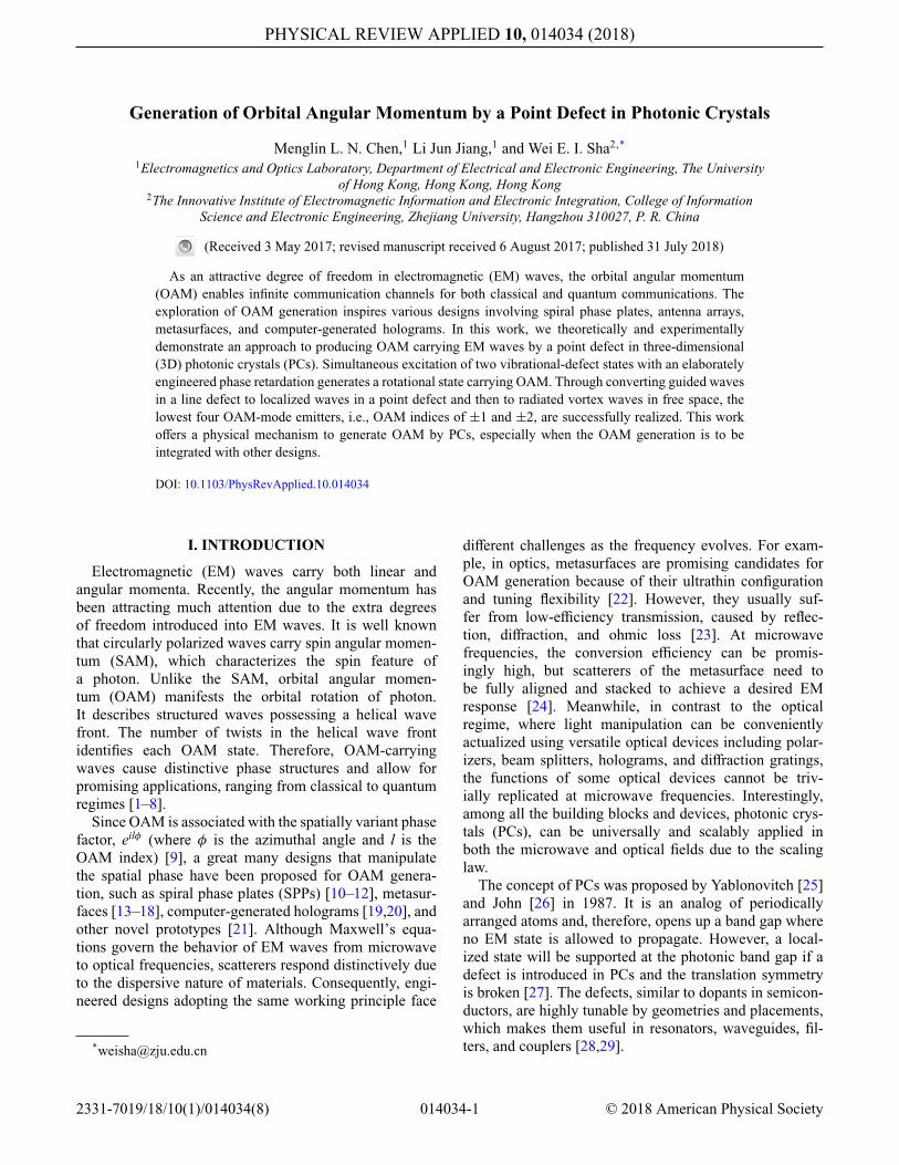
FIG. 5. The generation of OAM of order 2 by the proposed3D PC. (a) The geometry and corresponding electric-field dis-tribution: the guided wave from Port 1 is coupled to the defectmodes that radiate out through a circular opening. (b) The inten-sity and (c) the phase distributions of Ez at a transverse plane 30mm above the structure. The geometric parameters are as fol-lows: a = 12 mm, r = 2.5 mm, rd = 7.2 mm, rs = 1.65 mm,rc = 9.5 mm, and height h = 9.2 mm. The operating frequencyis 8.8 GHz.
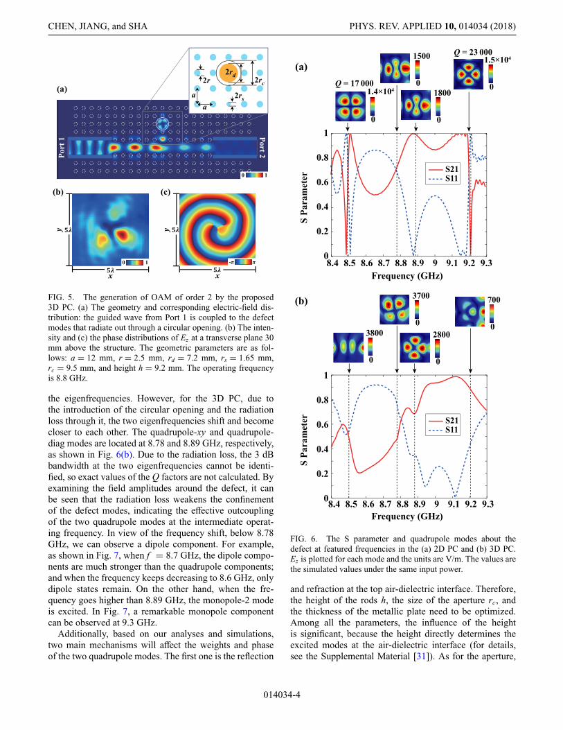
the eigenfrequencies. However, for the 3D PC, due tothe introduction of the circular opening and the radiationloss through it, the two eigenfrequencies shift and becomecloser to each other. The quadrupole-xy and quadrupole-diag modes are located at 8.78 and 8.89 GHz, respectively,as shown in Fig. 6(b). Due to the radiation loss, the 3 dBbandwidth at the two eigenfrequencies cannot be identi-fied, so exact values of the Q factors are not calculated. Byexamining the field amplitudes around the defect, it canbe seen that the radiation loss weakens the confinementof the defect modes, indicating the effective outcouplingof the two quadrupole modes at the intermediate operat-ing frequency. In view of the frequency shift, below 8.78GHz, we can observe a dipole component. For example,as shown in Fig. 7, when f = 8.7 GHz, the dipole compo-nents are much stronger than the quadrupole components;and when the frequency keeps decreasing to 8.6 GHz, onlydipole states remain. On the other hand, when the fre-quency goes higher than 8.89 GHz, the monopole-2 modeis excited. In Fig. 7, a remarkable monopole componentcan be observed at 9.3 GHz.
Additionally, based on our analyses and simulations,two main mechanisms will affect the weights and phaseof the two quadrupole modes. The first one is the reflection
8.5 8.6 8.7 8.8 9 9.1 9.2Frequency (GHz)
9.38.4
S Pa
ram
eter
8.90
0.2
0.4
0.6
0.8
1
0
1.5×10⁴
0
1.4×10⁴Q = 17 000
Q = 23 000
0
1500
0
1800
0
700
0
3700
0
3800
0
2800
8.5 8.6 8.7 8.8 9 9.1 9.2Frequency (GHz)
9.38.4
S Pa
ram
eter
8.90
0.2
0.4
0.6
0.8
1
S21S11
(a)
(b)
S21S11
FIG. 6. The S parameter and quadrupole modes about thedefect at featured frequencies in the (a) 2D PC and (b) 3D PC.Ez is plotted for each mode and the units are V/m. The values arethe simulated values under the same input power.
and refraction at the top air-dielectric interface. Therefore,the height of the rods h, the size of the aperture rc, andthe thickness of the metallic plate need to be optimized.Among all the parameters, the influence of the heightis significant, because the height directly determines theexcited modes at the air-dielectric interface (for details,see the Supplemental Material [31]). As for the aperture,
014034-4
GENERATION OF ORBITAL ANGULAR MOMENTUM... PHYS. REV. APPLIED 10, 014034 (2018)
FIG. 7. The projection of the complex field, which is abovethe 3D PC operated in the quadrupole state, along the azimuthaldirection onto the orthonormal basis of eilφ .
we choose it to be slightly larger than the concentrationregion of the field. If the aperture is too small, the radi-ated field will be distorted. When the aperture is largeenough, the radiated field retains the features of the fieldaround the defect. The influence of the aperture is lesssignificant than that of the height; and an optimal aper-ture size can be obtained in the simulation. Additionally, athicker top metallic plate will be detrimental to the radiatedOAM wave from the aperture—but its thickness does notmatter as long as it remains thin enough. The second mech-anism is the scattering and interference of waves at thewaveguide-scatterer-defect channel. The influence of thefeeding network and the size of the small scatterer fall intothis mechanism. In the proposed design, we feed the 3D PCstructure from one port by using the guided wave inside theline defect. The small scatterer is introduced to enhancethe mode conversion between the guided mode and thelocalized defect mode. It functions as a mode coupler thatmaximizes the coupling between the feeding channel andthe defect, and minimizes the transmitted power to theopposite port. By tuning the size of the scatterer, the cou-pling efficiency from the channel to the defect varies, as dothe weights of the two quadrupole modes. There is a trade-off between the high efficiency and purity of the producedOAM wave.
Additionally, the geometric parameters are scaled toshift the operating frequency from the microwave to theoptical regime. At optical frequencies, the two metallicplates are replaced by two aluminum plates and the dis-persion of aluminum is taken into consideration [34] (fordetails, see the Supplemental Material [31]).
C. OAM generation from dipole defect states
We make use of other defect modes to generate OAM ofdifferent orders. Here, we study the case for the generation
of OAM of order ±1 by superposing the dipole states.Importantly, there is a critical difference between thequadrupole and dipole modes: the dipole modes are doublydegenerate, while the quadrupole modes are splitted. Thedegenerate dipole modes cannot be exploited to induce arotational mode carrying OAM, which is demonstrated andexplained in the Supplemental Material [31].
To create an analog to the quadrupole case, webreak the C4 rotational symmetry of the defect byintroducing two sector cuts. Consequently, the degeneratedipole modes split into two dipole modes with differenteigenfrequencies, as shown in Fig. 8(a). Based on thevariational principle [28], concentration of the field into thehigher-permittivity material decreases the mode frequency,which is consistent with the numerical results. Similarly,by superposing the two modes with selected weights andphase values, an electric field with the spatial phase depen-dence of e±iφ can be obtained. Figure 8(b) shows one ofthe cases with l = −1.
f = 0.3618c/a f = 0.3392c/a
y
x
y
x
(a)
(b)
(c)
FIG. 8. The generation of OAM of order 1. (a) The real part ofelectric field of the two nondegenerate dipole modes by numeri-cal simulations. Two identical sectors with an angle of 20◦ are cutout from the defect rod (rd = 0.4a). (b) The amplitude and phasepatterns of the superposed electric field. The proper weights andphase in Eq. (1) are chosen to make the l = −1 mode dominant.(c) The full-wave simulated intensity and phase distributions ofEz at a transverse plane 30 mm above the 3D PC. The geometryof the 3D PC is the same as is shown in Fig. 5(a), except for thecut in the defect rod. The geometric parameters are as follows:a = 12 mm, r = 2.5 mm, rd = 4.8 mm, rs = 1.3 mm, rc = 6 mm,and h = 7 mm. The operating frequency is 9.7 GHz.
014034-5
CHEN, JIANG, and SHA PHYS. REV. APPLIED 10, 014034 (2018)
To effectively excite the two dipole modes, the defectis rotated 45◦ (for details, see the Supplemental Material[31]). In Fig. 8(c), we show the z component of the radi-ated electric field. An EM wave with an OAM of order 1is generated. The conversion efficiency is calculated to be24.9%.
It should be emphasized that the operating frequencyof 9.7 GHz in Fig. 8(c) is higher than the two eigenfre-quencies in the 2D PC, which are around 8.5 and 9.1 GHz[Fig. 9(a)]. In the 2D PC, when the operating frequencygoes higher than 9.1 GHz, the dipole mode becomes weak-ened and distorted. When the circular opening is inserted,the two eigenfrequencies shift, which is similar to thequadrupole case. In the 3D PC, the two dipole modesare shifted to 9.5 and 9.9 GHz [Fig. 9(b)] with less con-finement around the defect, which indicates the effectiveoutcoupling of the two dipole modes at 9.7 GHz.
D. Discussion
To generate OAM of order −1 and −2, we mirror thewhole structure, including the feeding ports about the yzplane. Based on this transformation rule (x → −x, y → y),the phase of one vibrational mode is flipped and that ofthe other remains unchanged. As a result, the excited rota-tional mode will reverse its helicity. Specifically, for thequadrupole structure, by feeding from the receiving port(Port 2) in Fig. 5(a), the radiated wave will carry OAM oforder −2. Our theory is verified by full-wave simulations,as presented in the Supplemental Material [31].
III. EXPERIMENTS
The generation of OAM by the proposed 3D PCs isverified by experiments. The implementation of the PCs inthe microwave regime adopts the approach used in Refs.[35,36]. The PCs are made of alumina rods with εr = 8.5(for details, see the Supplemental Material [31]). Theyare assembled between two flat aluminum plates, the topone of which has a cutting hole. The whole structure issurrounded by absorbers to avoid unwanted scattering. Theexperimental setup is shown in Fig. 10. A standard lin-early polarized horn antenna operating from 6.57 to 9.99
0
700
0
6.4×10⁴
0
4.5×10⁴
0
1400
0
1800
0
1500
8.5 9 9.5Frequency (GHz)
10
9.4 9.6 10Frequency (GHz)
10.29.2 9.8
S Pa
ram
eter
0
0.2
0.4
0.6
0.8
1
S Pa
ram
eter
0
0.2
0.4
0.6
0.8
1
(a)
(b)
S21S11
S21S11
FIG. 9. The S parameter and dipole modes about the defect atfeature frequencies in the (a) 2D PC and (b) 3D PC. Ez is plottedfor each mode and the units are V/m. The values are the simulatedvalues under the same input power.
GHz is connected to the transmitting port of a vector net-work analyzer (Agilent E5071C). The center of the hornantenna is aligned with the central line of the line defect in
probe
horn antenna absorber
(a) (b) FIG. 10. The experimentalsetup. (a) The measurement plat-form without the top aluminumplate. (b) The complete view ofthe measurement platform.
014034-6
GENERATION OF ORBITAL ANGULAR MOMENTUM... PHYS. REV. APPLIED 10, 014034 (2018)
)b()a(
)d()c(
0 1
y
x 160 mm
110
mm
0 1
y
x 160 mm
110
mm
-π π
y
x 160 mm
110
mm
-π π
y
x 160 mm
110
mm
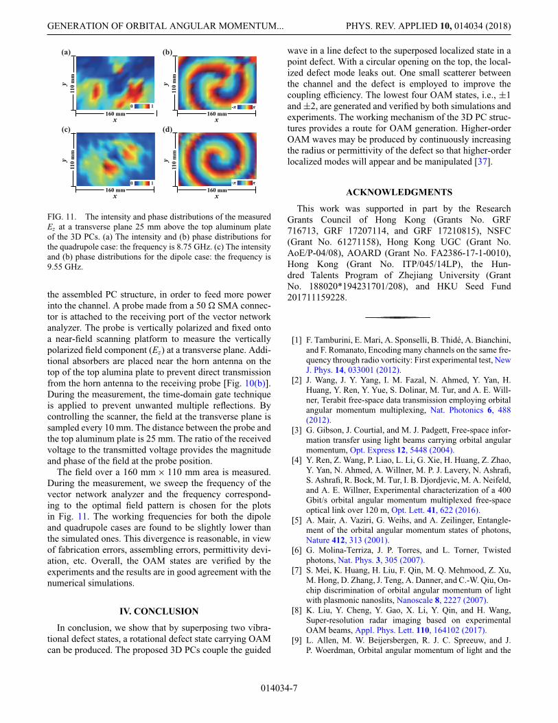
FIG. 11. The intensity and phase distributions of the measuredEz at a transverse plane 25 mm above the top aluminum plateof the 3D PCs. (a) The intensity and (b) phase distributions forthe quadrupole case: the frequency is 8.75 GHz. (c) The intensityand (b) phase distributions for the dipole case: the frequency is9.55 GHz.
the assembled PC structure, in order to feed more powerinto the channel. A probe made from a 50 � SMA connec-tor is attached to the receiving port of the vector networkanalyzer. The probe is vertically polarized and fixed ontoa near-field scanning platform to measure the verticallypolarized field component (Ez) at a transverse plane. Addi-tional absorbers are placed near the horn antenna on thetop of the top alumina plate to prevent direct transmissionfrom the horn antenna to the receiving probe [Fig. 10(b)].During the measurement, the time-domain gate techniqueis applied to prevent unwanted multiple reflections. Bycontrolling the scanner, the field at the transverse plane issampled every 10 mm. The distance between the probe andthe top aluminum plate is 25 mm. The ratio of the receivedvoltage to the transmitted voltage provides the magnitudeand phase of the field at the probe position.
The field over a 160 mm × 110 mm area is measured.During the measurement, we sweep the frequency of thevector network analyzer and the frequency correspond-ing to the optimal field pattern is chosen for the plotsin Fig. 11. The working frequencies for both the dipoleand quadrupole cases are found to be slightly lower thanthe simulated ones. This divergence is reasonable, in viewof fabrication errors, assembling errors, permittivity devi-ation, etc. Overall, the OAM states are verified by theexperiments and the results are in good agreement with thenumerical simulations.
IV. CONCLUSION
In conclusion, we show that by superposing two vibra-tional defect states, a rotational defect state carrying OAMcan be produced. The proposed 3D PCs couple the guided
wave in a line defect to the superposed localized state in apoint defect. With a circular opening on the top, the local-ized defect mode leaks out. One small scatterer betweenthe channel and the defect is employed to improve thecoupling efficiency. The lowest four OAM states, i.e., ±1and ±2, are generated and verified by both simulations andexperiments. The working mechanism of the 3D PC struc-tures provides a route for OAM generation. Higher-orderOAM waves may be produced by continuously increasingthe radius or permittivity of the defect so that higher-orderlocalized modes will appear and be manipulated [37].
ACKNOWLEDGMENTS
This work was supported in part by the ResearchGrants Council of Hong Kong (Grants No. GRF716713, GRF 17207114, and GRF 17210815), NSFC(Grant No. 61271158), Hong Kong UGC (Grant No.AoE/P-04/08), AOARD (Grant No. FA2386-17-1-0010),Hong Kong (Grant No. ITP/045/14LP), the Hun-dred Talents Program of Zhejiang University (GrantNo. 188020*194231701/208), and HKU Seed Fund201711159228.
[1] F. Tamburini, E. Mari, A. Sponselli, B. Thidé, A. Bianchini,and F. Romanato, Encoding many channels on the same fre-quency through radio vorticity: First experimental test, NewJ. Phys. 14, 033001 (2012).
[2] J. Wang, J. Y. Yang, I. M. Fazal, N. Ahmed, Y. Yan, H.Huang, Y. Ren, Y. Yue, S. Dolinar, M. Tur, and A. E. Will-ner, Terabit free-space data transmission employing orbitalangular momentum multiplexing, Nat. Photonics 6, 488(2012).
[3] G. Gibson, J. Courtial, and M. J. Padgett, Free-space infor-mation transfer using light beams carrying orbital angularmomentum, Opt. Express 12, 5448 (2004).
[4] Y. Ren, Z. Wang, P. Liao, L. Li, G. Xie, H. Huang, Z. Zhao,Y. Yan, N. Ahmed, A. Willner, M. P. J. Lavery, N. Ashrafi,S. Ashrafi, R. Bock, M. Tur, I. B. Djordjevic, M. A. Neifeld,and A. E. Willner, Experimental characterization of a 400Gbit/s orbital angular momentum multiplexed free-spaceoptical link over 120 m, Opt. Lett. 41, 622 (2016).
[5] A. Mair, A. Vaziri, G. Weihs, and A. Zeilinger, Entangle-ment of the orbital angular momentum states of photons,Nature 412, 313 (2001).
[6] G. Molina-Terriza, J. P. Torres, and L. Torner, Twistedphotons, Nat. Phys. 3, 305 (2007).
[7] S. Mei, K. Huang, H. Liu, F. Qin, M. Q. Mehmood, Z. Xu,M. Hong, D. Zhang, J. Teng, A. Danner, and C.-W. Qiu, On-chip discrimination of orbital angular momentum of lightwith plasmonic nanoslits, Nanoscale 8, 2227 (2007).
[8] K. Liu, Y. Cheng, Y. Gao, X. Li, Y. Qin, and H. Wang,Super-resolution radar imaging based on experimentalOAM beams, Appl. Phys. Lett. 110, 164102 (2017).
[9] L. Allen, M. W. Beijersbergen, R. J. C. Spreeuw, and J.P. Woerdman, Orbital angular momentum of light and the
CHEN, JIANG, and SHA PHYS. REV. APPLIED 10, 014034 (2018)
transformation of Laguerre-Gaussian laser modes, Phys.Rev. A 45, 8185 (1992).
[10] V. V. Kotlyar, A. A. Almazov, S. N. Khonina, and V. A.Soifer, Generation of phase singularity through diffractinga plane or Gaussian beam by a spiral phase plate, J. Opt.Soc. Am. A 22, 849 (2005).
[11] A. Niv, G. Biener, V. Kleiner, and E. Hasman, Spiralphase elements obtained by use of discrete space-variantsubwavelength gratings, Opt. Commun. 251, 306 (2005).
[12] L. Cheng, W. Hong, and Z. C. Hao, Generation of electro-magnetic waves with arbitrary orbital angular momentummodes, Sci. Rep. 4, 4814 (2014).
[13] S. M. Nohammadi, L. K. S. Daldorff, J. E. S. Bergman,R. L. Karlsson, B. Thidé, K. Forozesh, T. D. Carozzi, andB. Isham, Orbital angular momentum in radio—A systemstudy, IEEE Trans. Antennas Propag. 58, 565 (2010).
[14] N. Yu, P. Genevet, M. A. Kats, F. Aieta, J-P. Tetienne, F.Capasso, and Z. Gaburro, Light propagation with phase dis-continuities: Generalized laws of reflection and refraction,Science 334, 333 (2011).
[15] S. Chen, Y. Cai, G. Li, S. Zhang, and K. W. Cheah, Geomet-ric metasurface fork gratings for vortex-beam generationand manipulation, Laser Photonics Rev. 10, 322 (2016).
[16] Z. Zhao, J. Wang, S. Li, and A. E. Willner, Metamaterials-based broadband generation of orbital angular momentumcarrying vector beams, Opt. Lett. 38, 932 (2013).
[17] X. Wang, M. Q. Qi, T. Y. Chen, and T. J. Cui, Field-programmable beam reconfiguring based on digitally-controlled coding metasurface, Sci. Rep. 6, 20663(2016).
[18] M. L. N. Chen, L. J. Jiang, and W. E. I. Sha, Artifi-cial perfect electric conductor-perfect magnetic conduc-tor anisotropic metasurface for generating orbital angularmomentum of microwave with nearly perfect conversionefficiency, J. Appl. Phys. 119, 064506 (2016).
[19] N. R. Heckenberg, R. McDuff, C. P. Smith, and A.G. White, Generation of optical phase singularities bycomputer-generated holograms, Opt. Lett. 17, 221 (1992).
[20] V. Y. Bazhenov, M. V. Vasnetsov, and M. S. Soskin, Laserbeams with screw dislocations in their wavefronts, JETPLett. 52, 429 (1990).
[21] H. Ren, X. Li, Q. Zhang, and M. Gu, On-chip noninterfer-ence angular momentum multiplexing of broadband light,Science 352, 805 (2016).
[22] N. Yu and F. Capasso, Flat optics with designer metasur-faces, Nat. Mater. 13, 139 (2014).
[23] F. Bouchard, I. D. Leon, S. A. Schulz, J. Upham, E. Karimi,and R. W. Boyd, Optical spin-to-orbital angular momentum
conversion in ultra-thin metasurfaces with arbitrarytopological charges, Appl. Phys. Lett. 105, 101905(2014).
[24] M. L. N. Chen, L. J. Jiang, and W. E. I. Sha, Ultrathincomplementary metasurface for orbital angular momen-tum generation at microwave frequencies, IEEE Trans.Antennas Propag. 65, 396 (2017).
[25] E. Yablonovitch, Inhibited Spontaneous Emission in Solid-State Physics and Electronics, Phys. Rev. Lett. 58, 2059(1987).
[26] S. John, Strong Localization of Photons in Certain Disor-dered Dielectric Superlattices, Phys. Rev. Lett. 58, 2486(1987).
[27] E. Yablonovitch, T. J. Gmitter, R. D. Meade, A. M. Rappe,K. D. Brommer, and J. D. Joannopoulos, Donor and Accep-tor Modes in Photonic Band Structure, Phys. Rev. Lett. 67,3380 (1991).
[28] J. D. Joannopoulos, S. G. Johnson, J. N. Winn, and R.D. Meade, Photonic Crystals: Molding the Flow of Light(Princeton University Press, Princeton, 2011).
[29] K. Sakoda, Optical Properties of Photonic Crystals(Springer, Berlin, 2001).
[30] J. D. Joannopoulos, P. R. Villeneuve, and S. Fan, Pho-tonic crystals: Putting a new twist on light, Nature 386, 143(1997).
[31] For the FD method, additional details on the simulatedfield from the PCs, and a photograph of the fabricatedsamples, see the Supplemental Material at https://link.aps.org/supplemental/10.1103/PhysRevApplied.10.014034.
[32] L. D. Landau and E. M. Lifshitz, Quantum Mechanics:Non-Relativistic Theory (Pergamon Press, Oxford, 1977).
[33] W. C. Chew, Waves and Fields in Inhomogeneous Media(IEEE, New York, 1995).
[34] M. A. Ordal, L. L. Long, R. J. Bell, S. E. Bell, R. R. Bell,R. W. Alexander, and C. A. Ward, Optical properties of themetal Al, Co, Cu, Au, Fe, Pb, Ni, Pd, Pt, Ag, Ti, and W inthe infrared and far infrared, Appl. Opt. 22, 1099 (1983).
[35] X. Huang, Y. Yang, Z. H. Hang, Z.-Q. Zhang, and C. T.Chan, Geometric phase induced interface states in mutuallyinverted two-dimensional photonic crystals, Phys. Rev. B93, 085415 (2016).
[36] Y. Yang, X. Huang, and Z. H. Hang, Experimental Char-acterization of the Deterministic Interface States in Two-dimensional Photonic Crystals, Phys. Rev. Appl. 5, 034009(2016).
[37] P. R. Villeneuve, S. Fan, and J. D. Joannopoulos, Microcav-ities in photonic crystals: Mode symmetry, tunability, andcoupling efficiency, Phys. Rev. B 54, 7837 (1996).