WMP/Jun11/PHA3/B3/XTN PHA3/B3/XTN General Certificate of Education Advanced Subsidiary Examination June 2011 Physics PHA3/B3/XTN (Specifications A and B) Unit 3 Investigative and Practical Skills in AS Physics Route X Externally Marked Practical Assignment (EMPA) Instructions to Supervisors Confidential To be given immediately to the teacher(s) responsible for GCE Physics Open on receipt • These instructions are provided to enable centres to make appropriate arrangements for the Unit 3 Externally Marked Practical Assignment (EMPA). • It is the responsibility of the Examinations Officer to ensure that these Instructions to Supervisors are given immediately to the Supervisor of the EMPA.
Transcript
WMP/Jun11/PHA3/B3/XTN PHA3/B3/XTN
General Certificate of EducationAdvanced Subsidiary ExaminationJune 2011
Physics PHA3/B3/XTN
(Specifications A and B)
Unit 3 Investigative and Practical Skills in AS Physics
Route X Externally Marked Practical Assignment (EMPA)
Instructions to Supervisors Confidential
To be given immediately to the teacher(s) responsible for GCE Physics
Open on receipt
• These instructions are provided to enable centres to make appropriate
arrangements for the Unit 3 Externally Marked Practical Assignment (EMPA).
• It is the responsibility of the Examinations Officer to ensure that these Instructions
to Supervisors are given immediately to the Supervisor of the EMPA.
WMP/Jun11/PHA3/B3/XTN
2
INSTRUCTIONS TO THE SUPERVISOR OF THE EXTERNALLY MARKEDPRACTICAL ASSIGNMENT
General
Security/confidentiality
The instructions and details of the EMPA materials are strictly confidential. In no circumstancesshould information concerning apparatus or materials be given before the examination to a candidateor other unauthorised person.
The EMPA supplied by AQA at AS and at A2 for a given academic year must only be used in thatacademic year. It may be used for practice in later academic years.
Using information for any purpose beyond that permitted in this document is potentially malpractice. Guidance on malpractice is contained in the JCQ document Suspected Malpractice inExaminations and Assessments: Policies and Procedures.
The Examinations Officer should give copies of the Instructions to Supervisors (PHA3/B3/XTNand/or PHA6/B6/XTN) to the teacher entrusted with the preparation of the examination upon receipt.
Material from AQA
For each EMPA, AQA will provide
• Instructions to Supervisors• Section A Part 1 and Part 2 question paper/answer booklets• Section B EMPA written test papers.
Preparation / Centre responsibility
This practical assessment should be carried out after candidates have acquired the necessary skillsand after the appropriate sections of the specification have been taught so that candidates are familiarwith any specialist apparatus involved.
The assessment must be carried out between the dates specified by AQA.
It is the responsibility of the centre to ensure that each of the specified practical activities works withthe materials provided to the candidates.
The assessment and management of risks are the responsibility of the centre.
Practical Skills Verification (PSV)
Candidates must undertake the five practical activities specified, in order for them to demonstrate inthe EMPA that they can use apparatus appropriate to the teaching of Physics at this level. In doingso, candidates will be familiar with the equipment and skills they will use in the EMPA. The teachermust confirm on the front cover of the Section B Written Test that this requirement has been met.
Turn over �WMP/Jun11/PHA3/B3/XTN
3
Section A: Part 1 and Part 2
• Candidates should work individually and be supervised throughout. They should not discuss theirwork with other candidates at any stage.
• The work can be carried out in normal timetabled lessons and at a time convenient to the centre.Teachers will be in the best position to judge how many sessions are appropriate for candidates intheir own centre.
• The candidates’ work must be handed to the teacher at the end of each practical session and keptsecurely until the next stage of assessment.
• There is no specified time limit for Part 1 or Part 2 of Section A, however candidates should beinformed by the Supervisor of the expected timescale and timetable arrangements involved incarrying out the EMPA. Candidates must also be instructed that all readings must be entered inthe question paper/answer booklet provided and all working must be shown. Scrap paper mustnot be used.
Sharing equipment / working in groups
Candidates are to work individually. Where resources mean that equipment has to be shared, theteacher should ensure that the candidates complete the tasks individually. Where appropriate, spare sets of apparatus should be prepared to ensure that time is not lost due to failure of equipment.
Centres may choose to provide sufficient sets of apparatus for the candidates to work on Section A ina circus format with some candidates completing the questions in reverse order. In such cases thechangeover should be carefully supervised and the apparatus returned to its original state beforebeing used again.
Practical sessions
Before the start of the test the apparatus and materials for each candidate should be arranged, readyfor use, on the bench. The apparatus should not be assembled unless a specific instruction to do so ismade in these Instructions.
If any candidate is unable to perform any experiment, is performing an experiment incorrectly, or iscarrying out some unsafe procedure, the Supervisor is expected to give the minimum help required toenable the candidate to proceed. In such instances, the Supervisor’s Report should be completedwith the candidate’s name and number, reporting to the Examiner the nature and extent of theassistance given. No help may be given to candidates unable to proceed with the analysis of theirexperimental data.
Any failure of equipment that, in the opinion of the Supervisor, may have disadvantaged anycandidate should be detailed in the Supervisor’s Report.
4
Section B: EMPA written test
• The Section B EMPA written test should be taken as soon as convenient after completion ofSection A.
• This test must be carried out under controlled conditions and must be completed in a singleuninterrupted session.
• When carrying out the Section B EMPA written test, candidates should be provided with theircompleted copy of Section A Part 2 question paper/answer booklet.
• Supervisors should ensure that candidates understand that Section A Part 2 is for reference onlyand they must not make any written alterations to this previous work while undertaking Section B.
• The duration of the Section B EMPA written test is 1 hour 15 minutes except where candidateshave been granted additional time by AQA.
Administration
Candidates must not bring any paper-based materials into any session or take any assessmentmaterials away at the end of a session. Mobile phones or other communication devices are notallowed.
Modifications
The equipment requirements for the experimental tasks are indicated in these Instructions. Centresare at liberty to make any reasonable minor modifications to the apparatus which may be requiredfor the successful working of the experiment but it is advisable to discuss these with the AssessmentAdvisor or with AQA. A written explanation of any such modification must be given in theSupervisor’s Report.
Absent candidates
Candidates absent for any Part of Section A should be given an opportunity to carry out the practicalexercises before attempting the Section B EMPA written test. In extreme circumstances, when sucharrangements are not possible, the teacher can supply a candidate with class data. In this case, therewill be no evidence for Part 1 or Part 2, so no marks can be awarded for Section A.
Redrafting
Candidates may make only one attempt at a particular EMPA and redrafting is not permitted at anystage during the EMPA.
The Supervisor’s Report
Details should be given on the Supervisor’s Report (page 23) if
• any part of the equipment provided differs significantly from that specified in these Instructions • any help is given to candidates in the event of any failure of or difficulties with the equipment.
Supervisors must also include any numerical data that is specified in these Instructions. This mayinvolve the Supervisor performing an experiment before the test and collecting certain data. Suchdata should be given to the uncertainty indicated. Note that the Examiners may rely heavily on suchdata in order to make a fair assessment of a candidate’s work.
WMP/Jun11/PHA3/B3/XTN
5
Security of assignments
Candidates’ scripts and any other relevant materials, printed or otherwise, should be collected andremoved to a secure location at the end of each session. Under no circumstances should candidatesbe allowed to remove question papers from the examination room.
Once completed, each candidate’s completed EMPA should be collated in the following order• Section A Part 1• Section A Part 2• Section B EMPA written test.The assembled material should then be secured using a treasury tag.
Completed EMPAs are to be treated in the same manner as other completed scripts and should bekept under secure conditions before their despatch to the Examiner.
Submission of materials to the AQA Examiner
By the specified deadline centres should assemble and then despatch the following materials• collated candidates’ scripts, in candidate number order• the Supervisor’s Report (page 23 of these Instructions) if this is required by the Examiner.
WMP/Jun11/PHA3/B3/XTN
Turn over �
6
Section A Part 1: Question 1Candidates are to identify the SWG number of a wire and the type of material from which it is made.
The micrometer screw gauge and the 20 cm of 22 SWG constantan wire should be placed on thebench.
Once the terminal posts have been attached to the half-metre ruler, the longer piece of constantanwire should be threaded through the holes in the posts so that the free ends at either end are roughlythe same length. Pull the ends of the wire so that the wire goes into tension then screw down theterminal posts.Assemble the circuit shown in Figure 1 of the Section A Part 1 question paper / answer booklet sothat the wire forms a series circuit with the 2.2 Ω resistor (note that the mounted constantan wire isjoined to the rest of the circuit via the round terminal posts).Ensure that the pd across the resistor can be measured by attaching the clips at the ends of thevoltmeter leads to the exposed legs of the resistor.Check that when switch S is closed the pd across the resistor is about 70% to 80% of the emf.The candidates should be able to connect the voltmeter as shown in Figure 2 of the Section A Part 1question paper / answer booklet when the length of wire between clips P and Q is about 350 mm thepd shown on the voltmeter should be about 15% of the emf.
The examiners require no information for this question.
Supervisors should warn candidates that the 2.2 Ω resistor may get warm during theexperiment and remind them to open switch S once they have completed their measurements.
Apparatus• new D-type cell in holder capable of producing a steady output pd of at least 1.50 V, whilst
supplying a current of 0.4 A, or stabilised variable voltage dc mains voltage supply, in serieswith switch marked S (this can be the on/off switch on the PSU) with the open (off) and closed(on) positions clearly marked
• dc voltmeter capable of reading pd’s up to the emf of the dc supply in increments of 0.01 V orbetter; this meter can be a multimeter, set to suitable range, eg 2000 mV; leads should be connected to the inputs, terminating at crocodile clips labelled ‘P’ (to positive terminal) and ‘Q’ (to negative terminal)
• 2.2 Ω resistor, at least 2 W, tolerance not greater than 5%, eg Rapid 62-0235, mounted in such away that candidates can connect crocodile clips to the legs in order to measure the pd across theresistor
• about 60 cm of 22 SWG constantan wire, free from kinks, fixed using 4 mm terminal posts(Rapid 17-0215) mounted on a half-metre ruler; suitable holes should be drilled through themedian line of the ruler level with the 50 mm and 450 mm graduations, the wire should belabelled X, eg using a small sticky label close to one end
• connecting leads
Additional equipment• micrometer screw gauge capable of reading to 0.01 mm• about 20 cm of 22 SWG constantan wire
WMP/Jun11/PHA3/B3/XTN
7
Section A Part 1: Question 2Candidates are to determine the resistance of an unknown resistor using the circuit shown in Figure 3 of their question paper / answer booklet.
Duplicate without reduction or enlargement, sufficient copies of the template shown below, cuttingout around the dotted lines.
Apparatus• rotary 10 kΩ linear potentiometer, eg Rapid 65-0515, at least 0.2 W, fitted with pointer knob,
eg Rapid 32-0175; this is to be fitted with connecting leads and joined to the assembly describedbelow which involves the printed rotary scale
• one 2.2 kΩ resistor, metal film, at least 0.25 W, eg Rapid 62-0847; this is the fixed resistor inFigure 3
• one each of the following resistors, metal film, at least 0.25 W, Rapid references in brackets:1 kΩ (62-0824), 2.7 kΩ (62-0852), 5.6 kΩ (62-0867), 15 kΩ (62-0907), 27 kΩ (62-0927), 39 kΩ(62-0408); attach these with Sellotape to a postcard, printing the value of each resistor alongsidefor the candidates to see
• one 9.1 kΩ resistor, carbon film, at least 0.25 W, eg Rapid 62-0884, the value of this resistor tobe concealed from the candidate, eg using masking tape; this resistor should be labelled ‘U’
• component holder (eg two mounted crocodile clips) into which the candidate will insert resistors;the clips are to be labelled ‘C1’ and ‘C2’
• a dc supply with series switch labelled ‘S’; the terminal pd is at the discretion of the centre (seebelow)
• voltmeter (moving coil centre zero analogue type) or millivoltmeter (digital multimeter set to asuitable range) capable of reading to ± 0.2 mV or better, with connecting leads attached; one ofthese is to be connected directly to the sweep arm of the potentiometer
• one copy of the scale below which can be photocopied • a piece of hardboard or similar sheet material, 12 cm × 12 cm on which the rotary scale and
potentiometer are to be mounted
Turn over �
0180
20
200
40220
60
240
80
260 100
280
120
300
14032
0
160
340
WMP/Jun11/PHA3/B3/XTN
8
Fix the scale onto the square of hardboard and use Sellotape to ensure the edges are secure. Make ahole at the centre to accommodate the spindle of the potentiometer then secure this to the boardusing the locking nut supplied with the potentiometer. Cut down the spindle so that when the pointerknob is fitted this lies close to the surface of the scale.
Assemble the circuit shown in Figure 3 of the question paper / answer booklet, reproduced belowwith the resistance of the resistors shown. Note the connections made to the potentiometer (called a‘rotary potential divider’ in the question).
Connect the 1 kΩ resistor between C1 and C2 then close switch S. Ensure that the connections tothe voltmeter are such that when the control knob is rotated fully anti-clockwise, the voltmeter showsa negative reading and when the control knob is rotated fully clockwise the reading becomespositive. When the control knob is fully rotated anti-clockwise it is to the advantage of the candidates that theposition of the pointer shows a small positive reading, eg less than 50°, against the scale.Determine a terminal pd for the power supply that enables the meter to remain within full scalereading for either fully rotated position of the potentiometer.When the 1 kΩ resistor is replaced with a resistor of greater resistance, the position of the pointeragainst the scale when the voltmeter reads zero will become more positive.
Ensure that resistor U is in plain view.
The examiners require no information for this question.
0
180
20
200
40
220
60
240
80
260 100
280
120
300
140
320
160
340
2.2 kΩ
10 kΩ rotary
potential
divider
C1
C2
switch S
control knob of rotary potential divider
at the centre of the scale
to positive terminal
of the supply
to the voltmeter
to negative terminal
of the supplyview of the potentiometer
from above
V
WMP/Jun11/PHA3/B3/XTN
WMP/Jun11/PHA3/B3/XTN
9
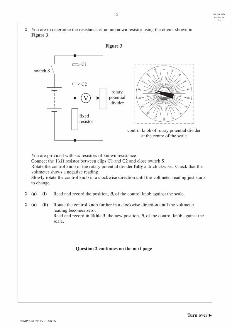
Section A Part 2Candidates are to investigate the variation of potential difference along a piece of conductive paper oftwo different widths.
Cut out a rectangle of conductive paper with dimensions 300 × 100 mm, then remove the areas (shownshaded in the diagram).
Apparatus• a rectangle of conductive paper, length 300 mm, width 100 mm; rolls of conductive (‘Teledeltos’)
paper are available from Philip Harris Ltd. (code B8A48252, roll dimensions 737 mm × 2 m,price £16.91)
• copper metal foil to produce two electrodes, each of width 10 mm, length 100 mm; copper metalfoil can be obtained from Philip Harris Ltd. (copper metal foil (0.13 mm) B8A67131)
• rectangular piece of thin material on which to mount the conductive paper strip, of minimumlength 300 mm, width 100 mm; the material should be such that the conductive paper can beglued to it, eg using paper glue, and the electrodes can be fixed to it using staples from a staplegun – suitable material could be sheet chipboard, notice-board (‘Sundealla’) or plywood
• a strip of paper tape, eg ticker tape, to be glued in place so that one edge lies along the centreline of the conductive paper, as shown in Figure 4 of the Section A part 2 question paper /answer booklet
for the circuit:• dc power supply; one, two, three or four 1.5 V D-type cell(s), in a holder, or regulated mains
supply with emf in range up to 6.0 V is ideal• digital voltmeter, capable of reading to 0.01 V or 0.001 V if used on 2000 mV full scale reading
(most 3Y digit LCD multimeters will be suitable) – the meter should be capable of reading up tothe emf of the supply; a probe should be connected to the positive terminal of meter, eg a multimeter test probe or small screwdriver connected via a crocodile clip to an insulated lead terminating at a 4 mm round plug
• one each of the following resistors, metal film, at least 0.25 W, Rapid references in brackets:2.7 kΩ (62-0852), 3.9 kΩ (62-0854)
• two further connecting leads terminated at both ends with 4 mm round plugs
additionally:• 300 mm perspex ruler
tools required and additional materials for assembly:• pencil and ruler to mark out conductive paper• staple gun for construction• scissors, sharp knife or scalpel for cutting conductive paper; use of cutting board recommended• strong adhesive tape, eg Gaffer tape• paper glue, eg Pritt Stick
Turn over �
rectangle of conductive paper of size 300 mm by 100 mm
rectangles to be removed (shown shaded)
of dimensions 20 mm by 170 mm
170 mm
170 mm
20 mm
20 mm
WMP/Jun11/PHA3/B3/XTN
10
Position the conductive paper centrally on to the baseboard and glue down or use Sellotape to fix theconductive paper strip in place. Form the electrodes from the sheet of copper foil then position theseso that they are flush with the edges of the paper and the exposed length of the conductive paper is280 mm.
Fix the electrodes in position using staples or some other method to provide good electrical contactwith the conductive paper.It is suggested that the connecting leads between the electrodes and the external circuit are made bysoldering stranded insulated wire to the exposed surface of the electrodes.Finally glue a strip of paper tape so that one edge of this is aligned with the median line of theconductive paper.
Connect the external circuit as shown below.
The apparatus is now complete: details of testing given below.
Use the voltmeter to confirm that a potential gradient exists along the length of the conductive paperand not just between the copper electrodes. The voltmeter reading V, should be zero at a distance xfrom the left-hand electrode in the region x = 140 to 150 mm.
baseboard
280 mm
probe
2.7 kΩ 3.9 kΩ
switch S
V
one edge of the paper tape along median line
WMP/Jun11/PHA3/B3/XTN
11
Candidates will be required to record V for x values starting at x = 20 mm and ending at x = 260 mmso contact resistances at the electrodes will not affect a candidate’s ability to perform the experiment.Thus there is no necessity to produce apparatus for which V = 0 V when x = 0 mm, or V = emf ofsupply when x = 280 mm.Values of V should increase linearly along the median line of the conductive paper strip and the rateof increase of V with x should become greater where the width of the paper narrows, ie at x = 120 mm.
The examiners require no information for this question.
Note that when completing Section B of the test candidates should be provided with their completedcopy of Section A Part 2, whereas candidates’ copies of Section Part 1 should not be made availableto them.
Turn over �
12
WMP/Jun11/PHA3/B3/XTN
1 You are to identify the diameter of a wire and the material from which it is made.
1 (a) Wire is manufactured in certain diameters under a system known as the EnglishStandard Wire Gauge, each diameter of wire being identified by a particular SWGnumber.Table 1 shows the diameter of wires with certain SWG numbers.
Table 1
1 (a) (i) You are provided with about 20 cm of loose wire.Use the micrometer screw gauge to determine d, the diameter of this wire.
1 (a) (ii) Identify the SWG number of the wire you have been given.(2 marks)
1 (b) You are provided with a circuit that includes a wire X, mounted on a ruler between twoterminals. The wire is connected in series with a 2.2 Ω resistor, a power supply and aswitch S. Connect the voltmeter in parallel with the resistor by attaching the clips Pand Q to the exposed legs of the resistor, as shown in Figure 1.
Figure 1
Section A Part 1
Do not writeoutside the
box
SWG number 16 20 22 24 28 30
diameter / mm 1.626 0.914 0.711 0.559 0.376 0.315
V 2.2 Ω
resistor
clip P
clip Q
wire X mounted
on a ruler between
two terminals
switch S
13
WMP/Jun11/PHA3/B3/XTN
1 (b) (i) Close switch S, then read and record the voltmeter reading, V1.
Open switch S and disconnect the clips from the resistor, then reattach P and Q at points along the wire X close to each of the round terminals, as shown inFigure 2.
Figure 2
1 (b) (ii) Close switch S, then read and record the new voltmeter reading, V2.
Open switch S before moving on to the next part of the question.
1 (b) (iii) Use the ruler readings to determine the length, x, of wire between the clips P and Q.
1 (b) (iv) The resistance of the wire between P and Q is given by 2.2 × .
Calculate the resistance of the wire between P and Q.(2 marks)
1 (c) The uncertainty in V1 and in V2 is ± 10 mV.
1 (c) (i) Calculate the percentage uncertainty in V1.
1 (c) (ii) Calculate the percentage uncertainty in V2.(2 marks)
1 (d) The percentage uncertainty in the resistance of the 2.2 Ω resistor is 5%.
Calculate the percentage uncertainty in the resistance of the wire between P and Q.(1 mark)
Question 1 continues on the next page
Do not writeoutside the
box
switch S
V
clip P clip Q
x
V1
V2
Turn over �
14
WMP/Jun11/PHA3/B3/XTN
1 (e) X is a wire of the same material and diameter as that you used in part (a).The material from which X has been made can be identified by measuring itsresistance per unit length, ie the resistance of 1 metre of the wire.Use your answers to part (a) and part (b) and the information contained in Table 2 todetermine the material from which X has been made.
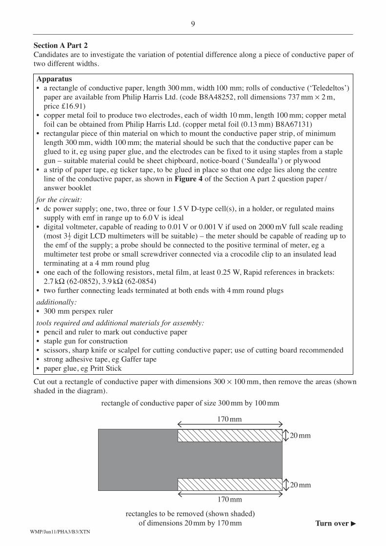
2 You are to determine the resistance of an unknown resistor using the circuit shown in Figure 3.
Figure 3
You are provided with six resistors of known resistance.Connect the 1 kΩ resistor between clips C1 and C2 and close switch S.Rotate the control knob of the rotary potential divider fully anti-clockwise. Check that thevoltmeter shows a negative reading.Slowly rotate the control knob in a clockwise direction until the voltmeter reading just startsto change.
2 (a) (i) Read and record the position, θ0 of the control knob against the scale.
2 (a) (ii) Rotate the control knob further in a clockwise direction until the voltmeterreading becomes zero.Read and record in Table 3, the new position, θ, of the control knob against thescale.
Question 2 continues on the next page
Turn over �WMP/Jun11/PHA3/B3/XTN
Do not writeoutside the
box
0
180
20
200
40
22060
240
80
260 100
280
120
300
140
320
160
340
fixed
resistor
rotary
potential
divider
C1
C2
switch S
control knob of rotary potential divider
at the centre of the scale
V
16
WMP/Jun11/PHA3/B3/XTN
2 (a) (iii) Remove the 1 kΩ resistor from clips C1 and C2 then repeat the procedure in part (a)(ii) to read values of θ when each of the remaining resistors of knownresistance R are connected, in turn, between clips C1 and C2.Record the values of θ for each of these resistors in Table 3 then complete theright-hand column to show the corresponding values of (θ – θ0).When you have completed these readings remove the resistor from C1 and C2and open switch S.
Table 3
(2 marks)
2 (b) Plot, on the grid provided, a graph with (θ – θ0) / ° on the vertical axis and R / kΩ onthe horizontal axis.
(3 marks)
2 (c) You are provided with another resistor, U, of unknown resistance RU.Connect U between clips C1 and C2 and close switch S.
2 (c) (i) Adjust the position of the control knob until the voltmeter reading becomes zerothen read and record the position, θU, of the control knob against the scale.
2 (c) (ii) Showing your working clearly, use your graph to determine RU.(2 marks)
END OF SECTION A PART 1
Do not writeoutside the
box
R / kΩ θ / ° (θ – θ0) / °
1.0
2.7
5.6
15.0
27.0
39.0
7
WMP/Jun11/PHA3/B3/XTN
1 In this experiment you are to investigate the variation of potential difference along a piece ofconductive paper of two different widths.A narrow strip of paper tape has been stuck to the conductive paper.Make a faint pencil mark on this paper tape at a distance, x = 20 mm from the left-handelectrode.
1 (a) Close switch S and place the tip of the probe in contact with the conductive paper nextto the pencil mark as shown in Figure 4.
Figure 4
1 (a) (i) Taking account of the sign shown on the meter, read and record V20, thevoltmeter reading when x = 20 mm.
1 (a) (ii) Repeating the procedure as above and taking account of the sign shown on themeter, read and record V260, the voltmeter reading when x = 260 mm.
1 (a) (iii) Evaluate . (1 mark)
Question 1 continues on the next page
Section A Part 2
Do not writeoutside the
box
17
tip of the probe in contactwith the conductive paper
narrow stripof paper tape
right-handelectrode
left-handelectrode
conductive paperx = 20 mm
x = 260 mm
switch S
V
Turn over �
V260
V20
1 (b) Using the same procedure as in part (a), investigate how V varies for values of xbetween 20 mm and 260 mm.You should take sufficient readings so that when a graph is plotted of these data, youcan establish clearly how V varies with x in both the wide and narrow parts of theconductive paper.Open switch S when you have completed your measurements.
Record all your measurements and observations.Note that the independent variable should be recorded in the left-hand column of yourtable.
(5 marks)
1 (c) Using all your data from part (a) and part (b), plot a graph with V on the vertical axisand x on the horizontal axis.
(9 marks)
END OF SECTION A PART 2
WMP/Jun11/PHA3/B3/XTN
Do not writeoutside the
box
18
15
6
WMP/Jun11/PHA3/B3/XTN
19
1 (a) Use your graph to determine
1 (a) (i) V0, the voltmeter reading, where x = 0 mm,
1 (a) (ii) V280, the voltmeter reading, where x = 280 mm,
1 (a) (iii) x0, the value of x in mm, when V = 0.(2 marks)
1 (b) (i) Determine the gradient, G, of your graph, where x = 200 mm.
1 (b) (ii) Evaluate
(4 marks)
2 Suppose that you repeated the experiment using a supply with a lower emf.
2 (a) State the effect, if any, this change will have on
2 (a) (i) your value of G,
2 (a) (ii) your value of .(2 marks)
2 (b) Explain the reasoning behind your answers to part (a).(1 mark)
3 (a) State without explanation how you could determine from your graph the value of x atwhich the width of the conductive paper changes.
(1 mark)
3 (b) Student A claims that to reduce the uncertainty in the value of x at which the width ofthe conductive paper changes, it would be a good idea to take more readings aroundthat point.Student B says it is better to make sure that there are enough readings so that bothstraight line regions can be accurately plotted.Explain which student has the better argument.
(2 marks)
Section B
Do not writeoutside the
box
G(280 – x0)V280 – V0
V260
V20
3
3
Turn over �
WMP/Jun11/PHA3/B3/XTN
20
4 In Section A Part 1 you measured the diameter of a wire using a micrometer screw gauge.
4 (i) Suggest a possible source of random error in this measurement.
4 (ii) Describe and explain a procedure that can be followed that may reduce the effect of thesource of random error you identified in part (i).
4 (iii) Suggest a procedure that can be followed that may reduce the effect of systematic errorin the determination of the diameter.
(4 marks)
5 In Section A Part 1 you were asked to record the position, θ, of the control knob against ascale when the voltmeter read zero and then to plot a graph from which the resistance RU, ofan unknown resistor was determined.A student who has carried out this experiment produces the graph shown in Figure 5.
Figure 5
R/kΩ
The student estimates that the uncertainty in each reading of θ is ± 1.5°.
5 (i) State the uncertainty in the calculated values of (θ – θ0)
5 (ii) Hence explain why the student would find it difficult to use Figure 5 to make anaccurate determination of RU if the resistance was approximately 25 kΩ.You may add detail to Figure 5 to illustrate your answer.
(3 marks)
Do not writeoutside the
box
4
00 10 20 30 40
50
100
150
200
250
300
3
(θ – θ0) / °
WMP/Jun11/PHA3/B3/XTN
21
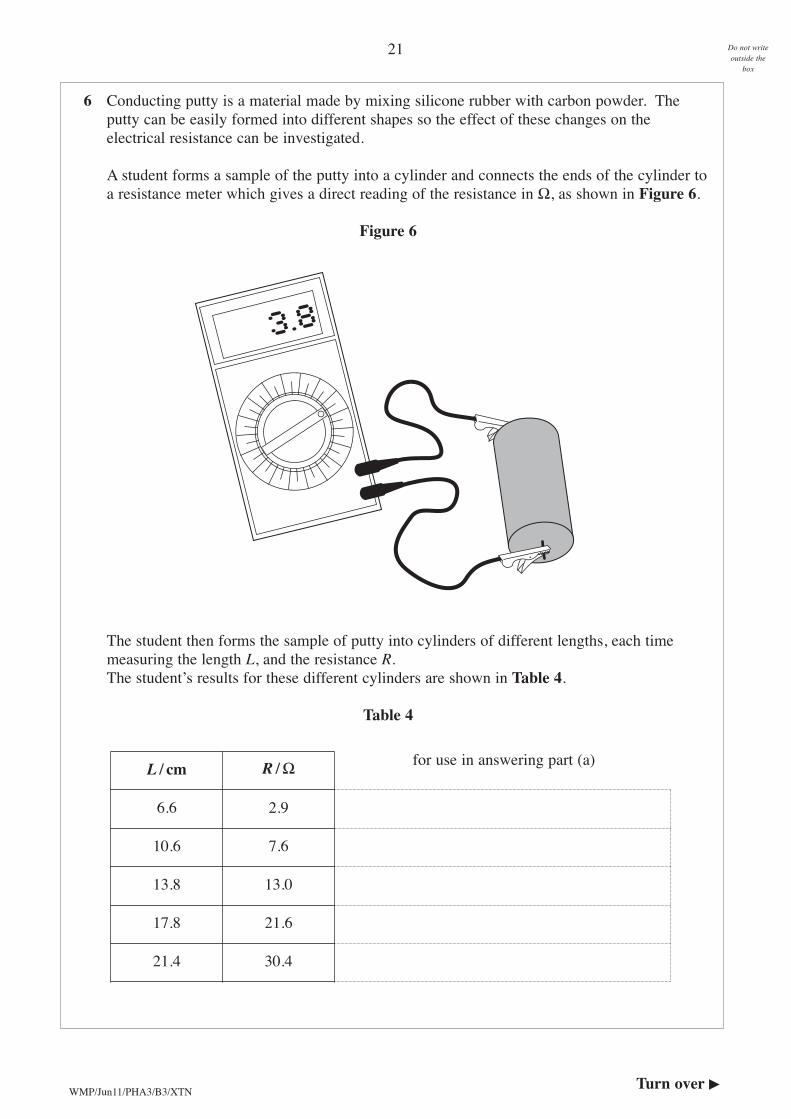
6 Conducting putty is a material made by mixing silicone rubber with carbon powder. Theputty can be easily formed into different shapes so the effect of these changes on theelectrical resistance can be investigated.
A student forms a sample of the putty into a cylinder and connects the ends of the cylinder toa resistance meter which gives a direct reading of the resistance in Ω, as shown in Figure 6.
Figure 6
The student then forms the sample of putty into cylinders of different lengths, each timemeasuring the length L, and the resistance R.The student’s results for these different cylinders are shown in Table 4.
Table 4
Do not writeoutside the
box
L / cm R / Ω
6.6 2.9
10.6 7.6
13.8 13.0
17.8 21.6
21.4 30.4
for use in answering part (a)
Turn over �
22
Theory suggests that R = kL2, where k is a constant.
6 (a) Show whether the data in Table 4 confirm the theory.You may use the right-hand column of Table 4 to assist you with this question.
(3 marks)
6 (b) Estimate the length of the cylinder, the resistance of which is shown being measured inFigure 6.
General Certificate of EducationAdvanced Subsidiary ExaminationJune 2011
23
PHYSICS
(SPECIFICATIONS A AND B) PHA3/B3/XTN
Unit 3
SUPERVISOR’S REPORT
When completed by the Supervisor, this Report must be attached firmly to the attendance list,or in the case of any problem affecting a particular candidate, it should be attached to the candidate’s script, before despatch to the Examiner.
Information to be provided by the centre
Section A Part 1Question 1 No information is requiredQuestion 2 No information is required
Section A Part 2Question 1 No information is required
Details of problems encountered by candidate...................................... candidate number .....................