22
Physikalisch- Technische Bundesanstalt Guideline DKD-R 8-2 Calibration of Multiple Delivery Dispensers Edition 01/2018 http://dx.doi.org/10.7795/550.20180313
| Date post: | 22-May-2018 |
| Category: |
Documents |
| Upload: | phungthien |
| View: | 217 times |
| Download: | 1 times |

Physikalisch- Technische
Bundesanstalt
Guideline DKD-R 8-2
Calibration of Multiple Delivery Dispensers
Edition 01/2018 http://dx.doi.org/10.7795/550.20180313

Calibration of Multiple Delivery Dispensers
http://dx.doi.org/10.7795/550.20180313
DKD-R 8-2
Version: 01/2018
Revision: 0
Page: 2 / 22
Deutscher Kalibrierdienst (DKD) – German Calibration Service Since its foundation in 1977, the DKD brought together calibration laboratories of industrial enterprises, research institutes, technical authorities, inspection and testing institutes. On 3 May 2011, the DKD was reestablished as a technical body of the PTB and the accredited laboratories. This body is called Deutscher Kalibrierdienst (DKD – German Calibration Service) and is under the direction of the PTB. The guidelines and guides elaborated by the DKD represent the state of the art in the respective technical areas of expertise and can be used by the Deutsche Akkreditierungsstelle GmbH (the German accreditation body – DAkkS) for the accreditation of calibration laboratories. The accredited calibration laboratories are now accredited and monitored by the DAkkS as legal successor of the DKD. They carry out calibrations of measuring devices and measuring standards for the measured values and measuring ranges defined during accreditation. The calibration certificates issued by these laboratories prove the traceability to national standards as required by the family of standards DIN EN ISO 9000 and DIN EN ISO/IEC 17025. Contact: Physikalisch-Technische Bundesanstalt (PTB) DKD Executive Office Bundesallee 100 38116 Braunschweig P.O. Box 38023 Braunschweig Telephone: 0049 531 5 92-8021 Internet: www.dkd.eu

Calibration of Multiple Delivery Dispensers
http://dx.doi.org/10.7795/550.20180313
DKD-R 8-2
Version: 01/2018
Revision: 0
Page: 3 / 22
Suggestion for the quotation of the references: Guideline DKD-R 8-2 Calibration of Multiple Delivery Dispensers, Edition 01/2018, Revision 0, Physikalisch-Technische Bundesanstalt, Braunschweig and Berlin. DOI: 10.7795/550.20180313 This document and all parts contained therein are protected by copyright and are subject to the Creative Commons user license CC by-nc-nd 3.0 (http://creativecommons.org/licenses/by-nc-nd/3.0/de/). In this context, “non-commercial” (NC) means that the work may not be disseminated or made publicly accessible for revenue-generating purposes. The commercial use of its contents in calibration laboratories is explicitly allowed.
Authors: The members of the DKD Technical Subcommittee Volume/Density. Published by the Physikalisch-Technische Bundesanstalt (PTB) for the German Calibration Service (DKD) as result of the cooperation between PTB and the Technical Committee Chemical Measurands and Material Properties / Technical Subcommittee Volume and Density of the DKD.

Calibration of Multiple Delivery Dispensers
http://dx.doi.org/10.7795/550.20180313
DKD-R 8-2
Version: 01/2018
Revision: 0
Page: 4 / 22
Foreword
DKD guidelines are application documents regarding the DIN EN ISO/IEC 17025 require-ments. The guidelines contain a description of the technical, process-related and the organizational procedures which accredited calibration laboratories use as a model for defining internal processes and regulations. DKD guidelines may become an essential component of the quality management manuals of calibration laboratories. By implementing the guidelines, it is ensured that the devices to be calibrated are all treated equally in the various calibration laboratories and that the continuity and verifiability of the work of the calibration laboratories are improved. The DKD guidelines should not impede the further development of calibration procedures and processes. Deviations from guidelines as well as new procedures are allowed in agreement with the accreditation body if there are technical reasons to support this action. The present guideline was drawn up by the Technical Committees Chemical Measurands and Material Properties / Technical Subcommittee Volume / Density in cooperation with PTB and the accredited calibration laboratories.
Calibrations by accredited laboratories provide the user with the security of reliable measuring results, increase the confidence of customers, enhance competitiveness in the national and international markets, and serve as metrological basis for the monitoring of measuring and test equipment within the framework of quality assurance measures. In preparation for the guideline, two pilot studies were carried out in the form of interlaboratory comparisons. The first pilot study (Interlaboratory comparison for the calibration of manual dispensers (direct displacement), reference number V/0006/12) served to establish an extensive data pool and included measurements by accredited calibration laboratories, each with two mechanical and two electronic multiple delivery dispensers. A subsequent interlaboratory comparison (Interlaboratory comparison for calibration of manual dispensers (direct displacement) Part 2 / focus on tip change, reference number V/0012/14) dealt with the influence of changing the dispenser tip; the measurements were carried out using the same calibration items. This guideline was drawn up by the Technical Committee Chemical Measurands and Material Properties and approved by the Board of the DKD.

Calibration of Multiple Delivery Dispensers
http://dx.doi.org/10.7795/550.20180313
DKD-R 8-2
Version: 01/2018
Revision: 0
Page: 5 / 22
Table of contents Foreword ............................................................................................................................... 4
1. Purpose and scope of application ................................................................................... 6
2. Symbols ......................................................................................................................... 7
2.1 Abbreviations and symbols ............................................................................................. 7
2.2 Units ............................................................................................................................... 8
3. Definitions ...................................................................................................................... 8
4. Aim of the calibration ...................................................................................................... 9
5. General requirements for the calibration capability of multiple delivery dispensers ......... 9
5.1 Requirements of the standard DIN EN ISO 8655...........................................................10
5.2 Requirements of the manufacturers′ product information ...............................................10
5.3 Requirements derived from observations during the calibration process .......................10
6. Ambient conditions ........................................................................................................11
7. Calibration procedure ....................................................................................................12
7.1 Calibration items ...........................................................................................................12
7.2 Accessories for dispensing ............................................................................................12
7.3 Additional notes for calibration (as a supplement to DIN EN ISO 8655-6) .....................12
8. Measurement uncertainty ..............................................................................................13
8.1 General .........................................................................................................................14
8.2 Uncertainty contributions of the balance ........................................................................15
8.3 Measurement uncertainty contributions “water temperature / water density” .................16
8.4 Measurement uncertainty contributions “air temperature and relative humidity” ............16
8.5 Measurment uncertainty contribution “atmospheric pressure” .......................................16
8.6 System-related influences .............................................................................................17
8.7 Repeatability .................................................................................................................18
8.8 Handling / Device ..........................................................................................................18
8.9 Measurement uncertainty budgets ................................................................................19
9. Bibliography ..................................................................................................................19
Appendix A Mechanical dispenser with dispenser tip 5 ml ...................................................20
Appendix B Motor-driven dispenser with dispenser tip 5 ml .................................................21
Calibration of Multiple Delivery Dispensers
http://dx.doi.org/10.7795/550.20180313
DKD-R 8-2
Version: 01/2018
Revision: 0
Page: 6 / 22
1. Purpose and scope of application
This guideline specifies the minimum requirements for the calibration procedure taking into account the special influences and the measurement uncertainty contributions for the calibration of multiple delivery dispensers. It applies to the calibration of:
- multiple delivery dispensers with positive displacement (motor-operated and non-motor operated)
This guideline does not apply to piston-operated pipettes with dispenser function. Other applicable standards and regulations
DIN EN ISO 8655 Teil 1, 5, 6
Volumenmessgeräte mit Hubkolben (English translation: Piston-operated volumetric apparatus, Part 1, 5, 6)
ISO/TR 20461 Determination of uncertainty for volume measurements made using the gravimetric method, November 2000 / Technical Corrigendum 1, December 2008
JCGM 100: 2008 Evaluation of measurement data – Guide to the expression of uncertainty in measurement, September 2008
EURAMET cg-18 Guidelines on the Calibration of Non-Automatic Weighing Instruments, Version 4.0 (11/2015)
EURAMET cg-19 Guidelines on the Determination of Uncertainty in Gravimetric Volume Calibration, Version 2.1 (03/2012)
DIN ISO 3696 Wasser für analytische Zwecke, Anforderungen und Prüfungen, Juni 1991 (English translation: Water for analytical laboratory use; specification and test methods)
DAkkS-DKD-3 Angabe der Messunsicherheit bei Kalibrierungen, 1. Neuauflage 2010, Deutsche Akkreditierungsstelle GmbH (English translation: Expression of the uncertainty of measurement in calibration, 1st new edition 2010)
Calibration of Multiple Delivery Dispensers
http://dx.doi.org/10.7795/550.20180313
DKD-R 8-2
Version: 01/2018
Revision: 0
Page: 7 / 22
2. Symbols
2.1 Abbreviations and symbols
Abbreviations / symbols
Explanation
a0 to a4 Constants (ITS-90 temperature scale) for the calculation of the water density
c Sensitivity coefficient
CV Random error as variation coefficient indicated in percent
eS Systematic measurement error
g Acceleration due to gravity
i Continuous index
k1 to k3 Constants (ITS-90 temperature scale) for the calculation of the air density
m Mass of the test liquid corresponding to the difference of the balance read-out
mE Evaporation loss
n Number of individual measurements
pL Atmospheric pressure
s Random measurement error
tW Temperature of the test liquid in °C
tL Air temperature during weighing in °C
tL0 273,15 K = 0 °C
tM Temperature of the multiple delivery dispenser during the measurement in °C
tM20 Reference temperature of the multiple delivery dispenser of 20 °C
u Standard measurement uncertainty
U Expanded measurement uncertainty (k = 2)
V0 Nominal volume
VS Selected volume
V20 Volume at a reference temperature of 20 °C
Z Correction factor describing the relationship between the mass determined during weighing and the volume
ρL Air density
ρW Density of the water used as test liquid
ρG Density of the standard weights used to calibrate the balance (equivalent to 8000 kg/m3)
φ Relative humidity
γ Cubic expansion coefficient of the entire system consisting of the dosage apparatus and the dispenser tip
TOL Tolerances for the random measurement error

Calibration of Multiple Delivery Dispensers
http://dx.doi.org/10.7795/550.20180313
DKD-R 8-2
Version: 01/2018
Revision: 0
Page: 8 / 22
2.2 Units
Units Explanation
µl Microlitre
ml Microgram
g Gram
mg Milligram
K Kelvin
°C Degree Celsius
hPa Hectopascal
g/cm3 Gram per cubic centimetre
µl/mg Microlitre per milligram
3. Definitions
Calibration certificate: Calibration certificates document the results of calibrations, including their measurement uncertainty. In this guideline, the term "calibration certificate" applies to the following documents (with restrictions):
- calibration certificates issued by calibration laboratories whose accreditation bodies have signed the ILAC-MRA (see www.ilac.org)
- calibration certificates issued by National Metrology Institutes with CMC entries (Appendix C of the CIPM MRA, see www.bipm.org).
The following terms, definitions and descriptions from DIN EN ISO 8655-1 are given for information purposes: Dispensers: Dispensers are used for repeated dispensing (dosing) of measured volumes of liquid. Single stroke dispensers deliver a single dose from each filling stroke. Multiple delivery dispensers or devices with gradual resolution deliver multiple doses from each filling stroke. Useful volume: The useful volume of a volume measuring device with variable volume is a sub-range of the nominal volume within which dispensing can be completed in compliance with the maximum permissible errors defined in the international standard ISO 8655. The upper limit of the useful volume is always the nominal volume. Unless otherwise specified by the supplier, the lower limit is 10 % of the nominal volume.

Calibration of Multiple Delivery Dispensers
http://dx.doi.org/10.7795/550.20180313
DKD-R 8-2
Version: 01/2018
Revision: 0
Page: 9 / 22
Selected volume: The selected volume VS of a volume measuring device with variable volume is the volume set by the user to dispense a selected volume from the useful volume of a piston-operated device. In the case of volume measuring devices with a fixed volume, the selected volume is the nominal volume. In addition to the standard ISO 8655, the Technical Subcommittee Volume / Density of the DKD Technical Committee Chemical Measurands and Material Properties laid down the following definition: Nominal volume According to the manufacturers, the tip volume is the nominal volume. In the case of hand-operated dispensers, the calibration of the nominal volume is metrologically not possible. The highest adjustable volume in the combination of dispenser and dispenser tip is therefore selected as nominal volume.
4. Aim of the calibration
The calibration of multiple delivery dispensers serves to define the deviation of the dispensed volume from the selected testing volume. The metrological correctness, including the consideration of the measurement uncertainty of the determined measurement results, is crucial for the implementation of quality-related metrological specifications in fields such as medicine and pharmacology. At the same time, the metrological traceability to national or international standards must be ensured. Note: According to DIN EN ISO/IEC 17025:2005, national and international interlaboratory comparisons / comparison measurements are required to ensure the comparability of calibration results. The standard DIN EN ISO/IEC 17043:2010 provides the basis for carrying out those comparisons.
5. General requirements for the calibration capability of multiple delivery dispensers
The general requirements for the calibration capability of multiple delivery dispensers can be divided into three main categories:
• requirements of the standard DIN EN ISO 8655
• requirements laid out in the manufacturers’ product information
• additional requirements from common practice

Calibration of Multiple Delivery Dispensers
http://dx.doi.org/10.7795/550.20180313
DKD-R 8-2
Version: 01/2018
Revision: 0
Page: 10 / 22
5.1 Requirements of the standard DIN EN ISO 8655
The requirements established in Part 1, Part 5 and Part 6 of DIN EN ISO 8655 must be adhered to in the calibrations, unless restrictions or specifications are made in this guideline.
5.2 Requirements of the manufacturers′ product information
These requirements differ according to the content and scope of the product information of the respective manufacturer. The most important requirements include:
- notes concerning operation, application exclusions, care and cleaning
- indication of type and manufacturer of the dispensing device
- notes on how to insert the dispenser tips
- specification of the dispenser tips to be used or of suitable dispenser tips with corresponding volume specifications
- indication of the manufacturer’s specification with the permissible tolerances of the random and systematic errors with reference to the adjustment (in/ex) and reference temperature
5.3 Requirements derived from observations during the calibration process
The requirements resulting from practical experience mainly concern the immediate usability of the multiple delivery dispenser. This includes:
- Labelling of the multiple delivery dispenser with
o serial number or another unique identification number
o information on manufacturer or type
- Identification of the tips used
- Avoidance of internal or external damage, e.g.
o cracks, fissures
o no unintentional adjustment of the set selection dial or counting mechanism (in the case of multiple delivery dispensers without motor drive)
- Checking of the charge condition of the rechargeable battery or battery and proper functioning of the sensor for detecting the dispenser tip
Calibration of Multiple Delivery Dispensers
http://dx.doi.org/10.7795/550.20180313
DKD-R 8-2
Version: 01/2018
Revision: 0
Page: 11 / 22
- Avoidance of dirt particles in the plug-in device for the dispenser tip
- Leakage test according to the manufacturer’s instructions Requirements related to the dispenser tips or the system consisting of dispenser / dispenser tip:
- use of original tips from the manufacturer or suitable dispenser tips with proof of technical conformity
- possible limitation in the identification of the dispenser tips for tips from other manufacturers,
- checking the dispenser tips for damage and dirt particles
- sufficient stability of the positioning of the dispenser tip in the plug-in device of the multiple delivery dispenser in accordance with the manufacturer’s instructions
6. Ambient conditions
To obtain accurate measurement results, the calibration must be carried out under stable ambient conditions. The ambient conditions
• air temperature
• relative humidity
• atmospheric pressure have an influence on the
• weighing technology
• calibration item
• test liquid and therefore, have a significant effect on the calibration result of the calibration item and the corresponding measurement uncertainty budget. Adherence to the specified ambient conditions by use of air conditioning is an important prerequisite for the calibration. The calibration must be conducted after the temperature between the calibration object and the environment has been equalized. An equalization time of at least 2 hours must be observed for the calibration item. The ambient conditions at the time of calibration are to be recorded. Fluctuations in the ambient conditions during calibration must also be observed and recorded.

Calibration of Multiple Delivery Dispensers
http://dx.doi.org/10.7795/550.20180313
DKD-R 8-2
Version: 01/2018
Revision: 0
Page: 12 / 22
7. Calibration procedure
The calibration of the calibration items is carried out using the gravimetric method in accordance with DIN EN ISO 8655-6. In this procedure, the mass of the liquid volume is determined from the indication of the weighing instrument in consideration of the air buoyancy, and is then converted into the volume via its density. The metrological traceability of the volume is realized by the physical quantity “mass” as reference standard. A full calibration includes the metrological recording of 10 measured values per testing volume. Preferably, analytical balances are used as measuring equipment. The minimum requirements for the balances to be used are specified in the standard ISO 8655-6.
7.1 Calibration items
Multiple delivery dispensers are available as mechanical and motor-operated measuring instruments. A dispenser tip that works according to the direct displacement principle is inserted into the dispenser. In many dispensers, the tip is detected by means of a sensor. The size of the maximum deliverable volume always depends on the system consisting of dispenser and dispenser tip. With most motor-driven dispensers it is possible to discharge the total volume of the tip at once.
7.2 Accessories for dispensing
Dispenser tips are used for volumetric dosing by means of multiple delivery dispensers. As a rule, unused dispenser tips are used. The typical sizes of dispenser tips vary from 0.1 ml to 50 ml. The calibration should be performed using one dispenser tip of only one size. The selection should be made according to the customer’s requirements. If there is no information regarding the selection of the tips, the recommendations of the manufacturer are to be followed.
7.3 Additional notes for calibration (as a supplement to DIN EN ISO 8655-6)
The first step of a measurement series is always performed after having aspirated the complete tip volume. Depending on the technical instruction of the instrument, the first step of aspiration is to be neglected. The following steps are carried out directly afterwards without new filling. Only when the remaining volume of the tip is no longer sufficient to carry out the next step, the entire volume is again aspirated. If a larger air bubble is detected after the initial filling, the tip must be emptied and refilled. A small air bubble is due to technical reasons and is not released due to the residual stroke lock. It has no measurable influence on the volume.
Calibration of Multiple Delivery Dispensers
http://dx.doi.org/10.7795/550.20180313
DKD-R 8-2
Version: 01/2018
Revision: 0
Page: 13 / 22
The dispensing process should always be carried out at the wall of the vessel (even when leaving out the first step). During this process, the tip should be held at a small angle (< 30°) to the wall of the vessel.
8. Measurement uncertainty
The measurement uncertainty is a parameter which is indicated together with the measurement result. The measurement uncertainty is determined by the measurement procedure and is assigned to the measurement result. The measurement uncertainty characterizes a range of values obtained by measurement which can reasonably be attributed to the measurand. As a matter of principle, the measurement uncertainty is calculated according to the international guideline JCGM 100 “Evaluation of measurement data – Guide to the expression of uncertainty in measurement” or according to the DAkkS-DKD guideline DAkkS-DKD-3. The measurement uncertainty should be expressed as a percentage. For the determination of the measurement uncertainty according to the gravimetric method, the standard ISO/TR 20461 is taken into account when establishing the measurement uncertainty budget. According to ISO / TR 20461, the volume for the reference temperature of 20 °C is calculated as follows:
[ ])(1 20MM
LW
LG
G
20 ttm
V −−⋅−−
⋅= γρρρρ
ρ (1)
Furthermore, the calculation formulae for the water density and the air density must be considered. For the standard measurement uncertainty, the following equation is yielded:
( ) …+⋅
∂∂+⋅
∂∂+⋅
∂∂+⋅
∂∂= )()()()( L
2
2
L
20L
2
2
L
20w
2
2
w
202
2
2020
2pu
p
Vtu
t
Vtu
t
Vmu
m
VVu (2)
The calculation of the sensitivity coefficients in equation (2) is described in the standard ISO/TR 20461. The following cause-effect diagram gives a comprehensive representation of all the factors influencing the measurement uncertainty that are considered in this guideline.

Calibration of Multiple Delivery Dispensers
http://dx.doi.org/10.7795/550.20180313
DKD-R 8-2
Version: 01/2018
Revision: 0
Page: 14 / 22
Fig. 1: Illustration of the influences to be considered in the estimation of the expected value
and measurement uncertainty in the calibration of multiple delivery dispensers
8.1 General
The accredited measurement uncertainty budgets for the measurands and the calibration procedures form the prerequisites to ensure the national and international comparability of the measurement results. The establishment of the measurement uncertainty budgets for the gravimetric calibration procedure includes:
• the optimization and definition of the calibration procedure
• the definition of specific ambient conditions
• the metrological evaluation of the various calibration items from different device manufacturers
• the consideration of the process-related handling contribution. The process-related handling contribution depends on the type of device and on the operator. This measurement uncertainty contribution contains random and systematic components. If individual influences on the calibration result and its measurement uncertainty cannot be determined exactly, their contribution to the uncertainty must be estimated and taken into account. The basis/source of this estimation must be indicated. The measurement conditions of the calibration must be described as completely as possible because the measurement uncertainties also depend on the conditions of use. In comparison measurements, the calibration conditions should be defined to ensure the comparability of the measurement results. The measurement uncertainties described below serve as a basis to determine the smallest assignable measurement uncertainties (best measurement capabilities) which are reflected in the accreditation.
Calibration of Multiple Delivery Dispensers
http://dx.doi.org/10.7795/550.20180313
DKD-R 8-2
Version: 01/2018
Revision: 0
Page: 15 / 22
The term “best measurement capability” is defined in the guideline DAkkS-DKD-3.
8.2 Uncertainty contribution of the balance
Basically, it can be assumed that the ambient conditions during the calibration of the balance and during the gravimetric calibration of the dispensers are nearly identical. The calibration task, the measuring range and the resolution of the balance as well as the associated measurement uncertainty must be adapted to each other to ensure a user-specific usage according to EURAMET cg-18. The recommendations set out in ISO 8655 Part 6 are to be observed. The balance should be calibrated user-specifically, i.e. the measuring range of the calibration task should correspond to the calibrated weighing range. Prior to the gravimetric calibration of the dispensers, it must be ensured that the balance is calibrated according to EURAMET cg-18. Thus, the contributions that are assigned to the weighing – resolution of the balance, repeatability, eccentric loading – are included in the current calibration certificate of the balance. The calibration certificate of the balance used is the basis for further measurement uncertainty considerations of the gravimetric method. The uncertainty contribution “reading”, or respectively, “resolution of the balance”, has to be considered in the measurement uncertainty budget twice (tare weighing and gross weighing). The result of the weighing is the difference between the weight values (indicated values). Since the calibration is carried out according to the gravimetric method, a regular observation of the balance is of great importance. As a result, intermediate tests with suitable calibrated weights are carried out within the calibration period. An additional contribution arises from the drift of the balance due to aging and wear. This influence can be determined by means of intermediate tests or re-calibration. As a result, this contribution can be taken into account after long-term observations, and conclusions can be drawn. This contribution has not been considered in the attached measurement uncertainty budgets. The influence of the ambient temperature according to the specifications of the manufacturer is another contribution to be taken into account; this contribution can be found in the manufacturer’s specifications. During the dosing process with the calibration items, free liquid surfaces occur, so that loss by evaporation should be taken into account as a contribution. The evaporation loss can either be determined or estimated – on the basis of one’s own experience – with respect to the volume of the calibration item.
Calibration of Multiple Delivery Dispensers
http://dx.doi.org/10.7795/550.20180313
DKD-R 8-2
Version: 01/2018
Revision: 0
Page: 16 / 22
8.3 Measurement uncertainty contributions “water temperature / water density”
Before and during calibration, it must be ensured that the water used is free of bubbles and that it is adjusted to the air temperature (deviation of ≤ 0.5 K). Otherwise, the measurement uncertainty must be adjusted accordingly. Compliance with the specified ambient conditions “air temperature/relative humidity” during calibration is ensured by an appropriate air conditioning system. Hence, also the stability of the water temperature is positively influenced. The temperature of the test liquid (water) used is determined by means of a calibrated thermometer. The measurement uncertainty budget takes into account the uncertainty of the thermometer and the fluctuation of the water temperature (< 0.2 K) during calibration. The influence of the temperature inside the weighing vessel may be neglected. The uncertainty for calculating the water density according to [1] is estimated to be 10 . 10–6 as the precise isotope ratio and the gas content are not known. The water density is needed to calculate the volume of the test liquid.
8.4 Measurement uncertainty contributions “air temperature and relative humidity”
During calibration, the ambient conditions “air temperature” and “relative humidity” are realized in specified parameters by air conditioning. The measurement data of the ambient conditions are recorded and documented by means of suitable, calibrated thermometers and humidity sensors. The air density may be calculated according to equation (4) of the calibration guide EURAMET cg-19. The fluctuations of the air temperature during calibration should be ≤ 0.5 K. The relative humidity should be ≥ 45 %. Low air humidities may lead to static charging of the balances. Note: The calibration of multiple delivery dispensers with smallest assignable measurement uncertainties requires the ambient conditions to remain within small tolerance limits.
8.5 Measurement uncertainty contribution “atmospheric pressure”
The atmospheric pressure should be recorded and documented by means of a calibrated precision barometer. The atmospheric pressure is a measurand needed to calculate the air density and, thus, the volume. The precision barometer used should have a resolution of 1 hPa or better.

Calibration of Multiple Delivery Dispensers
http://dx.doi.org/10.7795/550.20180313
DKD-R 8-2
Version: 01/2018
Revision: 0
Page: 17 / 22
8.6 System-related influences
In most cases, the dosing unit of the multiple delivery dispenser consists of thin-walled plastic. During the calibration, the temperature of the dosing units is therefore adjusted almost entirely to the temperature of the test liquid. The test liquid and the dosing unit itself – with the plastics that are commonly used – have a similar coefficient of thermal expansion (in the case of the dosing units, this includes the expansion of the cross section). Therefore, both expansions counterbalance each other to a large extent (negative correlation). These are the two influences described in equation (17) and equation (20) of ISO/TR 20461. If the expansion of the cross section of the dosing unit is not included in the measurement uncertainty budget, then this represents a maximum estimate of the influence of test liquid’s temperature. The inclusion of the thermal expansion of the cross section of the dosing unit into the measurement budget can therefore be omitted. By way of example, a corresponding determination of these influences is included in the budgets provided in the appendices. They are marked by an asterisk and largely counterbalance each other. The sensitivity coefficient is the product of the dispensed volume and the quadratic expansion coefficient of the material of the dispenser tip. For common materials, the thermal expansion of the tip’s cross section can be estimated to be 260·10–6·1/K. The thermal expansion of the stroke-determining handle and of the upper part do not correlate with the water temperature. Usually, components made of metal or special plastic are used to determine the stroke. For hand-operated devices, a maximum increase in temperature of the handle parts of a few degrees (1 °C to 3 °C) must be expected. The effect of volume deviation due to hand warmth is only a small fraction of the uncertainty allowance for handling and device and can be integrated into it (see paragraph 8.8). The budgets contained in the appendices include a corresponding determination of these influences. In the budget, they are marked by a double asterisk. The sensitivity coefficient is the product of the dispensed volume and the linear expansion coefficient of the material of the stroke-determining components. The thermal expansion of the stroke-determining components can be estimated to be 50·10–6·1/K for common materials (special plastic). If the volume is to be related to a reference temperature that deviates from the measuring temperature (temperature of the test liquid) as expressed by equation (6) in ISO / TR 20461, this requires the knowledge of the coefficient of thermal expansion of the complete system (dispenser tip and dosing unit) including the uncertainty of this coefficient. In this case, the resulting uncertainty according to equation (15) in ISO/TR 20461 must be taken into account in the measurement uncertainty budget. As opposed to volume measuring devices made of glass, data concerning the thermal expansion of the complete system are usually not available; therefore, it is recommended to indicate the temperature of the water as reference temperature. Thus, this contribution is omitted.

Calibration of Multiple Delivery Dispensers
http://dx.doi.org/10.7795/550.20180313
DKD-R 8-2
Version: 01/2018
Revision: 0
Page: 18 / 22
8.7 Repeatability
The repeatability is the empirical standard deviation of the mean value of a series of 10 individual measurements. The empirical standard deviation characterizes the dispersion of the measured values under the same measurement conditions during the calibration of the aforementioned volume measuring devices and is calculated according to the following formula:
2
i
1
( )
1
n
i
V V
sn
=
−=
−
∑ (3)
The standard measurement uncertainty (confidence interval of the mean value) of the repeatability is determined according to the “Type A evaluation of uncertainty” (GUM) and is calculated according to the following formula:
( )s
u sn
= (4)
Experience shows that the experimental standard deviation is approximately one third of the tolerance specified by the manufacturer for the repeatability (maximum random error). As best approximation and maximum consideration, the uncertainty contribution can be estimated at 1/3 of the manufacturer’s tolerances for the random measurement error of the measurement volume. The following applies:
1( )
3= ⋅u s TOL (5)
where “TOL” equates to the tolerances for the random measurement error in µl. A normal distribution can be assumed.
8.8 Handling / Device
When calculating the measurement uncertainty for a specific type of instrument, the design of the instrument must be taken into account, since the components of the measurement uncertainty (device and handling contribution) depend on this design. To calculate the handling contribution, it is recommended to take the manufacturer’s tolerances of the accuracy and the coefficient of variation (CV) as a basis. Taking into account all influences for handling, an uncertainty contribution of 1/10 of the manufacturer’s tolerance is used as best approximation. This contribution is a minimum value which must not be fallen short of. A rectangular distribution can be assumed.

Calibration of Multiple Delivery Dispensers
http://dx.doi.org/10.7795/550.20180313
DKD-R 8-2
Version: 01/2018
Revision: 0
Page: 19 / 22
Based on a statistical analysis of selected tolerances provided by the manufacturer, the following values are recommended to create the uncertainty budget. These are percentage values which refer to the volume that can be dispensed by the respective dispenser tip.
Size of the dispenser tip Process-related handling contribution
0.1 ml 0.15 %
0.2 ml 0.12 %
0.5 ml 0.09 %
1 ml / 1.25 ml 0.07 %
2.5 ml / 5 ml 0.06 %
> 5 ml 0.05 %
These are minimum values which can also be selected to be larger if this should be required due to experience and the manufacturer’s tolerances.
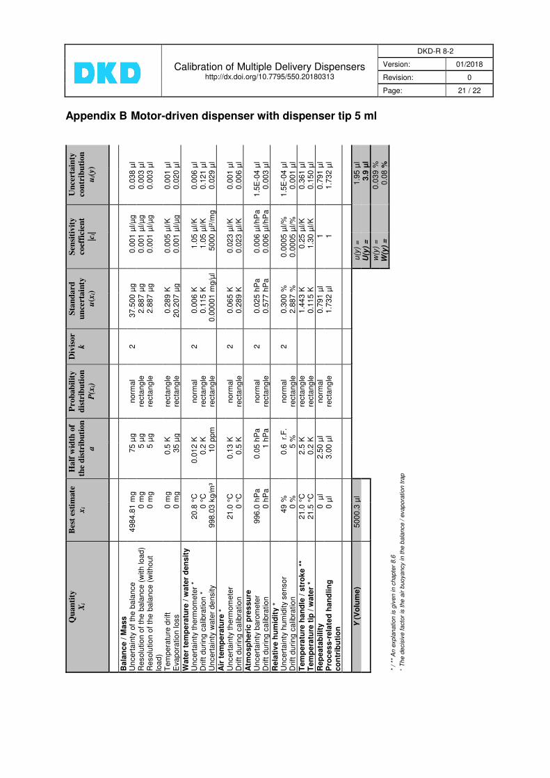
8.9 Measurement uncertainty budgets
Note: As appendices to this guideline, two measurement uncertainty budgets have been
added. Appendix A Mechanical dispenser with dispenser tip 5 ml
(highest adjustable volume 1 ml) Appendix B Motor-driven dispenser with dispenser tip 5 ml The guideline DKD-R 8-2 serves as basis for the calibration practice in the accredited calibration laboratories when calibrating multiple delivery dispensers; it depicts basic influences on the measurement uncertainty. This ensures the comparability between the calibration laboratories and offers the possibility of national and international comparison measurements. The aim is to integrate the findings resulting from the guideline activities of the DKD Technical Committee into the further development of the standard DIN EN ISO 8655.
9. Bibliography
[1] M. TANAKA, G. GIRARD, R. DAVIS, A. PEUTO, N. BIGNELL: Recommended table for the density of water between 0 °C and 40 °C based on recent experimental reports; Metrologia 2001, 38, 301-309

Calibration of Multiple Delivery Dispensers
http://dx.doi.org/10.7795/550.20180313
DKD-R 8-2
Version: 01/2018
Revision: 0
Page: 20 / 22
Appendix A Mechanical dispenser with dispenser tip 5 ml
(highest adjustable volume 1 ml)
Qu
an
tity
X
i
Bes
t es
tim
ate
xi
Ha
lf w
idth
of
the
dis
trib
uti
on
a
Pro
ba
bil
ity
d
istr
ibu
tion
P
(xi)
Div
isor
k
Sta
nd
ard
u
nce
rta
inty
u
(xi)
Sen
siti
vity
co
effi
cien
t |c
i|
Un
cert
ain
ty
con
trib
uti
on
u
i(y)
Ba
lan
ce
/ M
ass
U
nce
rta
inty
of
the b
ala
nce
9
96
.81
mg
27
µg
stu
de
nt
2.0
6
13
.10
7 µ
g
0.0
01
µl/µ
g
0.0
13
µl
Re
so
lutio
n o
f th
e b
ala
nce (
with lo
ad)
0 m
g
5 µ
g
recta
ng
le
1,7
32
2
.88
7 µ
g
0.0
01
µl/µ
g
0.0
03
µl
Re
so
lutio
n o
f th
e b
ala
nce (
with
out
loa
d)
0 m
g
5 µ
g
recta
ng
le
1,7
32
2
.88
7 µ
g
0.0
01
µl/µ
g
0.0
03
µl
Tem
pe
ratu
re d
rift
0
mg
0.5
K
recta
ng
le
1,7
32
0
.28
9 K
0
.00
1 µ
l/K
0
.00
03
µl
Evap
ora
tio
n loss
0 m
g
15
µg
recta
ng
le
1,7
32
8
.66
0 µ
g
0.0
01
µl/µ
g
0.0
09
µl
Wa
ter
tem
pe
ratu
re /
wa
ter
den
sit
y
Un
ce
rta
inty
th
erm
om
ete
r *
20.8
°C
0.0
12
K
no
rma
l 2
0
.00
6 K
0.2
1 µ
l/K
0.0
01
µl
Dri
ft d
uri
ng
ca
libra
tio
n *
0
°C
0
.2 K
re
cta
ng
le
1,7
32
0
.11
5 K
0.2
1 µ
l/K
0.0
24
µl
Un
ce
rta
inty
wate
r de
nsity
998
.03
kg/m
³ 10
pp
m
recta
ng
le
1,7
32
0
.00
00
1 m
g/µ
l 1
000
µl²
/mg
0.0
06
µl
Air
te
mp
era
ture
+
Un
ce
rta
inty
th
erm
om
ete
r 2
1.0
°C
0.1
3 K
no
rma
l 2
0
.06
5 K
0.0
045
µl/K
0
.00
03
µl
Dri
ft d
uri
ng
ca
libra
tio
n
0 °
C
0,5
K
recta
ng
le
1,7
32
0
.28
9 K
0.0
045
µl/K
0.0
01
µl
Atm
osp
he
ric
pre
ssu
re
Un
ce
rta
inty
baro
me
ter
99
6.0
hP
a
0.0
5 h
Pa
no
rma
l 2
0
.02
5 h
Pa
0.0
012
µl/h
Pa
3.0
E-0
5 µ
l D
rift
duri
ng
ca
libra
tio
n
0 h
Pa
1
hP
a
recta
ng
le
1,7
32
0
.57
7 h
Pa
0.0
012
µl/h
Pa
0.0
01
µl
Re
lati
ve
hu
mid
ity +
U
nce
rta
inty
hum
idity
se
nso
r 49
%
0.6
%
no
rma
l 2
0
.30
0 %
0.0
001
µl/%
3.0
E-0
5 µ
l D
rift
duri
ng
ca
libra
tio
n
0 %
5
%
recta
ng
le
1,7
32
2
.88
7 %
0.0
001
µl/%
0
.00
03
µl
Tem
pera
ture
han
dle
/ s
tro
ke *
* 2
1.0
°C
2
.5 K
re
cta
ng
le
1,7
32
1
.44
3 K
0.0
5 µ
l/K
0.0
72
µl
Tem
pera
ture
tip
/ w
ate
r *
21.5
°C
0
.2 K
re
cta
ng
le
1,7
32
0
.11
5 K
0.2
6 µ
l/K
0.0
30
µl
Re
pe
ata
bil
ity
0
µ
l 0.8
3 µ
l no
rma
l 3
0
.26
4 µ
l 1
0.2
64
µl
Pro
ce
ss-r
ela
ted
han
dli
ng
c
on
trib
uti
on
0
µl
0.6
0 µ
l re
cta
ng
le
1,7
32
0
.34
6 µ
l 1
0.3
46
µl
Y (
Vo
lum
e)
10
00
.10
µl
u(y
) =
0.4
4 µ
l
U(y
) =
0.8
9 µ
l
w
(y)
=
0.0
44
%
W
(y)
=
0
.09
%
* /
** A
n e
xpla
na
tion is g
ive
n in
cha
pte
r 8
.6
+ T
he d
ecis
ive
facto
r is
the
air b
uoya
ncy in t
he b
ala
nce /
eva
pora
tio
n t
rap
Calibration of Multiple Delivery Dispensers
http://dx.doi.org/10.7795/550.20180313
DKD-R 8-2
Version: 01/2018
Revision: 0
Page: 21 / 22
Appendix B Motor-driven dispenser with dispenser tip 5 ml
Qu
an
tity
X
i
Bes
t es
tim
ate
xi
Ha
lf w
idth
of
the
dis
trib
uti
on
a
Pro
ba
bil
ity
d
istr
ibu
tio
n
P(x
i)
Div
iso
r k
Sta
nd
ard
u
nce
rta
inty
u
(xi)
Sen
siti
vit
y
coef
fici
ent
|ci|
Un
cert
ain
ty
con
trib
uti
on
u
i(y)
Bala
nc
e / M
ass
U
ncert
ain
ty o
f th
e b
ala
nce
4
984
.81
mg
75
µg
norm
al
2
37.5
00
µg
0.0
01
µl/µ
g
0.0
38
µl
Resolu
tio
n o
f th
e b
ala
nce (
with lo
ad
) 0 m
g
5 µ
g
recta
ngle
1,7
32
2.8
87
µg
0.0
01
µl/µ
g
0.0
03
µl
Resolu
tio
n o
f th
e b
ala
nce (
witho
ut
loa
d)
0 m
g
5 µ
g
recta
ngle
1,7
32
2.8
87
µg
0.0
01
µl/µ
g
0.0
03
µl
Tem
pera
ture
drift
0 m
g
0.5
K
recta
ngle
1,7
32
0.2
89
K
0.0
05
µl/K
0.0
01
µl
Eva
pora
tio
n loss
0 m
g
35
µg
recta
ngle
1,7
32
20.2
07
µg
0.0
01
µl/µ
g
0.0
20
µl
Wate
r te
mp
era
ture
/ w
ate
r d
en
sit
y
Uncert
ain
ty th
erm
om
ete
r *
20.8
°C
0.0
12
K
norm
al
2
0.0
06
K
1.0
5 µ
l/K
0.0
06
µl
Drift
durin
g c
alib
ratio
n *
0 °
C
0.2
K
recta
ngle
1,7
32
0.1
15
K
1.0
5 µ
l/K
0.1
21
µl
Uncert
ain
ty w
ate
r de
nsity
998.0
3 k
g/m
³ 10
ppm
re
cta
ngle
1,7
32
0.0
0001
mg/µ
l 5000
µl²/m
g
0.0
29
µl
Air
tem
pe
ratu
re +
U
ncert
ain
ty th
erm
om
ete
r 21.0
°C
0.1
3 K
norm
al
2
0.0
65
K
0.0
23
µl/K
0.0
01
µl
Drift
durin
g c
alib
ratio
n
0 °
C
0.5
K
recta
ngle
1,7
32
0.2
89
K
0.0
23
µl/K
0.0
06
µl
Atm
osp
he
ric
pre
ssu
re
Uncert
ain
ty b
aro
mete
r 996.0
hP
a
0.0
5 h
Pa
norm
al
2
0.0
25
hP
a
0.0
06
µl/hP
a
1.5
E-0
4 µ
l D
rift
durin
g c
alib
ratio
n
0 h
Pa
1 h
Pa
re
cta
ngle
1,7
32
0.5
77
hP
a
0.0
06
µl/hP
a
0.0
03
µl
Rela
tiv
e h
um
idit
y +
U
ncert
ain
ty h
um
idity s
enso
r 49
%
0.6
r.
F.
norm
al
2
0.3
00
%
0.0
005
µl/%
1.5
E-0
4 µ
l D
rift
durin
g c
alib
ratio
n
0 %
5 %
re
cta
ngle
1,7
32
2.8
87
%
0.0
005
µl/%
0.0
01
µl
Tem
pera
ture
han
dle
/ s
tro
ke *
* 21.0
°C
2.5
K
recta
ngle
1,7
32
1.4
43
K
0.2
5 µ
l/K
0.3
61
µl
Tem
pera
ture
tip
/ w
ate
r *
21.5
°C
0.2
K
recta
ngle
1,7
32
0.1
15
K
1.3
0 µ
l/K
0.1
50
µl
Rep
eata
bil
ity
0
µl
2.5
0 µ
l norm
al
3
0.7
91
µl
1
0.7
91
µl
Pro
ces
s-r
ela
ted
han
dlin
g
co
ntr
ibu
tio
n
0 µ
l 3.0
0 µ
l re
cta
ngle
1,7
32
1.7
32
µl
1
1.7
32
µl
Y (
Vo
lum
e)
5000
.3 µ
l
u(y
) =
1.9
5 µ
l
U(y
) =
3.9
µl
w
(y)
=
0.0
39
%
W
(y)
=
0.0
8 %
*
/ **
An
expla
na
tion
is g
ive
n in
cha
pte
r 8.6
+ T
he d
ecis
ive f
acto
r is
the
air b
uo
ya
ncy in t
he b
ala
nce /
evap
ora
tion t
rap

Editor: Physikalisch-Technische Bundesanstalt Deutscher Kalibrierdienst Bundesallee 100 38116 Braunschweig www.dkd.eu www.ptb.de


