PIAGGIO WOULD LIKE TO THANK YOU for choosing one of its products. We have prepared this booklet to help you to get the very best from your scooter. Please read it carefully before riding the scooter for the first time. It contains information, tips and precautions for using your scooter. It also describes features, details and devices to assure you that you have made the right choice. We believe that if you follow our suggestions, you will soon get to know your new vehicle and it will serve you well for a long time to come. This booklet forms an integral part of the scooter; should the scooter be sold, it must be transferred to the new owner. Typhoon 50
Transcript
PIAGGIO WOULD LIKE TO THANK YOU
for choosing one of its products. We have prepared this booklet to help you to get the very best from your scooter. Please read it carefully before ridingthe scooter for the first time. It contains information, tips and precautions for using your scooter. It also describes features, details and devices to assureyou that you have made the right choice. We believe that if you follow our suggestions, you will soon get to know your new vehicle and it will serve youwell for a long time to come. This booklet forms an integral part of the scooter; should the scooter be sold, it must be transferred to the new owner.
Typhoon 50
The instructions given in this manual are intended to provide a clear, simple guide to using your scooter; this booklet also details routine maintenanceprocedures and regular checks that should be carried out on the vehicle at an authorised Dealer or Service Centre. The booklet also containsinstructions for simple repairs. Any operations not specifically described in this manual require the use of special tools and/or particular technicalknowledge: to carry out these operations refer to any authorised Dealer of Service Centres.
2
Personal safety
Failure to completely observe these instructions will result in serious risk of personalinjury.
Safeguarding the environment
Sections marked with this symbol indicate the correct use of the vehicle to prevent dam-aging the environment.
Vehicle intactness
The incomplete or non-observance of these regulations leads to the risk of seriousdamage to the vehicle and sometimes even the invalidity of the guarantee.
The signs that you see on this page are very important. They are used to highlight thoseparts of the booklet that should be read with particular care. As you can see, each signconsists of a different graphic symbol, making it quick and easy to locate the varioustopics.
Locking the steering wheel.................................................... 9Releasing the steering wheel................................................ 10
Switch direction indicators........................................................ 10Horn button............................................................................... 11Light switch............................................................................... 11Start-up button.......................................................................... 12
Opening the saddle............................................................... 12Keys.......................................................................................... 13Identification.............................................................................. 13Bag clip..................................................................................... 14
USE.............................................................................................. 15Checks...................................................................................... 16Refuelling.................................................................................. 16Tyre pressure............................................................................ 18Running in................................................................................. 19Starting up the engine............................................................... 19Difficult start up......................................................................... 20Stopping the engine.................................................................. 21Catalytic silencer....................................................................... 22Automatic transmission............................................................. 22Safe driving............................................................................... 23
MAINTENANCE........................................................................... 25Hub oil level.............................................................................. 26Tyres......................................................................................... 27Spark plug dismantlement........................................................ 28Removing the air filter............................................................... 29Secondary air system............................................................... 29Checking the brake oil level...................................................... 30Battery....................................................................................... 31
Checking the electrolyte level................................................ 32Long periods of inactivity.......................................................... 33Fuses........................................................................................ 34Front light group........................................................................ 36
Headlight adjustment............................................................. 36Front direction indicators........................................................... 37Rear optical unit........................................................................ 38Rear turn indicators................................................................... 38Rear-view mirrors...................................................................... 39Idle adjustment.......................................................................... 39Front disc brake........................................................................ 40Rear drum brake....................................................................... 41Puncture.................................................................................... 42Periods of inactivity................................................................... 42Cleaning the vehicle.................................................................. 43
SPARE PARTS AND ACCESSORIES........................................ 55Warnings................................................................................... 56
P= Coolant temperature indicator (not available on this model);
8
1 Ve
hicl
e
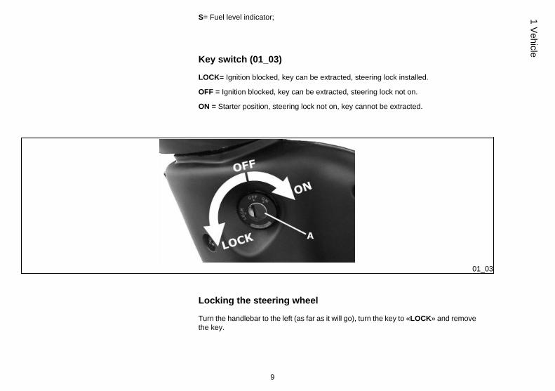
S= Fuel level indicator;
Key switch (01_03)
LOCK= Ignition blocked, key can be extracted, steering lock installed.
OFF = Ignition blocked, key can be extracted, steering lock not on.
ON = Starter position, steering lock not on, key cannot be extracted.
01_03
Locking the steering wheel
Turn the handlebar to the left (as far as it will go), turn the key to «LOCK» and removethe key.
9
1 Vehicle
CAUTION
DO NOT TURN THE KEY TO «LOCK» OR «OFF» WHILE RIDING.
Releasing the steering wheel
Reinsert the key and turn it to «OFF».
CAUTION
DO NOT TURN THE KEY TO «LOCK» OR «OFF» WHILE RIDING.
01_04
Switch direction indicators (01_04)
To set the left turn indicators flashing, move lever «B» to the left; to set the right turnindicators flashing, move it to the right. The lever automatically returns to the centralposition and the indicators remain on. To turn the indicators off, press the lever towardsthe switch.
10
1 Ve
hicl
e
01_05
Horn button (01_05)
Horn button «E»
01_06
Light switch (01_06)
0 = Low beam and side light
1 = High beam and side light
11
1 Vehicle
01_07
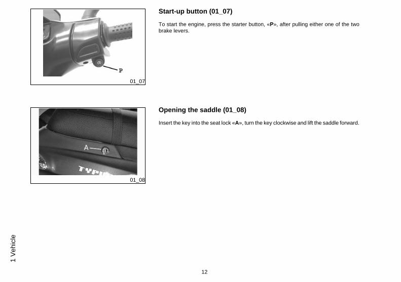
Start-up button (01_07)
To start the engine, press the starter button, «P», after pulling either one of the twobrake levers.
01_08
Opening the saddle (01_08)
Insert the key into the seat lock «A», turn the key clockwise and lift the saddle forward.
12
1 Ve
hicl
e
01_09
Keys (01_09)
The vehicle is supplied with two keys (one spare) which serve to start the engine andunlock the saddle compartment. The keys are accompanied by a tag marked with theidentification code to be quoted when ordering duplicates.
WARNING
WE RECOMMEND KEEPING THE DUPLICATE KEY TOGETHER WITH ITS CODEIN A SAFE PLACE AND NOT ON THE VEHICLE
01_10
01_11
Identification (01_10, 01_11)
The identification numbers consist of a prefix stamped on the chassis and on the en-gine, followed by a number. They should always be given when requesting spareparts. We recommend that you check that the prefix and chassis number stamped onthe vehicle correspond with those in the vehicle documents.
CAUTION
BE REMINDED THAT ALTERING IDENTIFICATION REGISTRATION NUMBERSCAN LEAD TO SERIOUS PENAL SANCTIONS (IMPOUNDING OF THE VEHICLE,ETC.).
13
1 Vehicle
01_12
Bag clip (01_12)
To use the bag hook mounted under the front of the saddle, part "A" needs to bepulled slightly forward.
14
1 Ve
hicl
e
Typhoon 50
Chap. 02Use
15
Checks
Before using the vehicle, check:
1. That the petrol tank and oil reservoir are full.
2. The oil level in the rear hub.
3. That the tyres are correctly inflated.
4. That the headlight, rear light and turn indicators are in working order.
5. That the front and rear brakes are in working order.
6. The fluid level in the brake pump reservoir.
02_01
02_02
Refuelling (02_01, 02_02)
Fill the fuel tank «A» as shown in the diagram, with unleaded petrol with minimumoctane rating of 95.The rider is informed when fuel is low by the fuel warning light on the instrument panel;see the "Control Panel" section.Top up the oil tank «B» using the recommended oil.The minimum oil level is shown by the oil warning light on the instrument panel; seethe "Control Panel" section.Should this warning light come on, then the next time you are filling up with fuel, andin any case before travelling another 150 km, you should top up the oil tank.Each time the engine is switched on (electrical start up), the mixer oil reserve warninglight should come on, and should go off when the starter button is released «P». If thewarning light fails to come on, it is faulty. Should this happen, contact an AuthorisedPiaggio Service Centre.Should the 'mixer' device be removed and refitted, it needs to be bled. However, theducts can remain without oil. After these operations, refill the fuel tank with 3 lit. of amixture with 2% of the recommended oilSubsequent refuelling must be performed using fuel only.
16
2 U
se
CAUTION
SHUT OFF THE ENGINE BEFORE REFUELLING WITH PETROL. PETROL ISHIGHLY FLAMMABLE. DO NOT LET PETROL SPILL FROM THE TANK OR WHILEREFUELLING
CAUTION
DO NOT BRING NAKED FLAMES OR CIGARETTES NEAR THE MOUTH OF THEFUEL TANK: FIRE HAZARD. ALSO AVOID INHALING HARMFUL VAPOURS.
CAUTION
THE USE OF OILS AND SPARK PLUGS OTHER THAN THOSE RECOMMENDEDCAN SHORTEN THE LIFE OF THE ENGINE.
Recommended productsAGIP CITY TEC 2T
Mixer oilsynthetic oil for 2-stroke engines: JASO FC, ISO-L-EGD
CharacteristicTopping up mixer oil tank
with at least 0.5 ÷ 1 lit.
Oil mixer tank
In plastic, with a capacity of 1.5 lit. (including reserve ~0.500 lit).
17
2 Use
02_03
Tyre pressure (02_03)
CAUTION
TYRE PRESSURE SHOULD BE CHECKED WHEN TYRES ARE COLD.INCOR-RECT TYRE PRESSURE CAUSES ABNORMAL TYRE WEAR AND MAKES RID-ING DANGEROUS.
TYRES MUST BE REPLACED WHEN THE TREAD REACHES THE WEAR LIMITSSET FORTH BY LAW.
CharacteristicFront tyre pressure
1.2 bar
Rear tyre pressure
1.7 bar
Rear tyre pressure (with rider and luggage)
1.9 bar
18
2 U
se
02_04
Running in (02_04)
WARNING
DURING THE FIRST 1000 KM DO NOT RIDE THE VEHICLE OVER 80% OF ITSMAXIMUM SPEED. AVOID TWISTING THE THROTTLE GRIP FULLY OR KEEP-ING A CONSTANT SPEED ALONG LONG SECTIONS OF ROAD. AFTER THEFIRST 1000 KM, GRADUALLY INCREASE SPEED UNTIL REACHING THE MAX-IMUM PERFORMANCE.
02_05
Starting up the engine (02_05)
The scooter is fitted with automatic transmission with a regulator and centrifugal clutch.Therefore always start the engine with the throttle at a minimum; to start-off from still,progressively twist the throttle grip.
The vehicle is equipped with a fuel valve and a starter that switch on automatically assoon as the engine is started.
In order to start the engine, it is necessary to pull either the rear brake lever "B" or thefront brake lever "C", before pressing the starting button, "A ", so as to disengage thesafety switches.
1: Put the motorscooter on its stand "E"; check that the rear tire is off the ground.
2: Keep the throttle closed.
3: Insert the key into the ignition switch, "D", and turn to the ON position.
4: Push the starter button «A» after pulling the rear brake lever «B» or the front brakelever «C».
19
2 Use
CAUTION
DO NOT CARRY OUT THESE OPERATIONS IN CLOSED AREAS SINCE EX-HAUST GASES ARE TOXIC.
CAUTION
DUE TO THE HIGH TEMPERATURES THE CATALYTIC CONVERTER CANREACH, ALWAYS TAKE CARE, WHEN PARKING THE SCOOTER, THAT THEEXHAUST DOES NOT COME INTO CONTACT WITH FLAMMABLE MATERIALS,TO AVOID SERIOUS BURNS.
02_06
Difficult start up (02_06)
Possible causes for engine starting difficulties and suggested actions:
1.Carburettor flooded. Place the vehicle on the centre stand and check that the reartyre is off the ground. Open the throttle fully and press the starter button for five sec-onds and then stop for five seconds. If the engine does not start after a few attempts,let the engine sit for a few minutes and then repeat the above operations. Do not keepthe button pressed for more than 20 seconds when attempting to start the engine.
2. In the case of battery inefficiency. Put the motorscooter on its stand "E"; makesure that the rear wheel is off the ground, turn the ignition key «D» to the «ON» positionand use the kick-starter.
3.Fuel tank empty. After refuelling the scooter, start the engine by pressing the starterbutton «A» with the throttle at a minimum to provide maximum aspiration for the tap.If the scooter fails to start even after taking the steps described above, contact anAuthorised Piaggio Service Centre.
20
2 U
se
CAUTION
ALWAYS PLACE THE VEHICLE ON ITS STAND BEFORE KICK STARTING.
WARNING
TAMPERING MAY CAUSE SERIOUS ENGINE MALFUNCTION.
02_07
Stopping the engine (02_07)
Stop acceleration, then turn the key switch "D" to "OFF " to turn off the engine (ex-tractable key).
CAUTION
DUE TO THE HIGH TEMPERATURES THE CATALYTIC CONVERTER CANREACH, ALWAYS TAKE CARE, WHEN PARKING THE SCOOTER, THAT THEEXHAUST DOES NOT COME INTO CONTACT WITH FLAMMABLE MATERIALS,TO AVOID SERIOUS BURNS.
21
2 Use
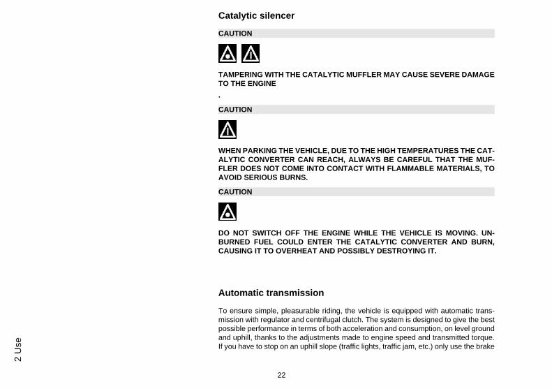
Catalytic silencer
CAUTION
TAMPERING WITH THE CATALYTIC MUFFLER MAY CAUSE SEVERE DAMAGETO THE ENGINE.
CAUTION
WHEN PARKING THE VEHICLE, DUE TO THE HIGH TEMPERATURES THE CAT-ALYTIC CONVERTER CAN REACH, ALWAYS BE CAREFUL THAT THE MUF-FLER DOES NOT COME INTO CONTACT WITH FLAMMABLE MATERIALS, TOAVOID SERIOUS BURNS.
CAUTION
DO NOT SWITCH OFF THE ENGINE WHILE THE VEHICLE IS MOVING. UN-BURNED FUEL COULD ENTER THE CATALYTIC CONVERTER AND BURN,CAUSING IT TO OVERHEAT AND POSSIBLY DESTROYING IT.
Automatic transmission
To ensure simple, pleasurable riding, the vehicle is equipped with automatic trans-mission with regulator and centrifugal clutch. The system is designed to give the bestpossible performance in terms of both acceleration and consumption, on level groundand uphill, thanks to the adjustments made to engine speed and transmitted torque.If you have to stop on an uphill slope (traffic lights, traffic jam, etc.) only use the brake
22
2 U
se
to keep the vehicle still, leaving the motor running at idling speed. Using the motor tokeep the vehicle still can cause the clutch to overheat. This problem is due to thefriction of the clutch parts on the clutch bell. It is therefore recommended to avoidconditions of prolonged clutch slippage leading to clutch overheating (for example, aswell as the situation described above, riding uphill fully laden on steep slopes or start-ing off on slopes greater than 25%, etc.):
1. Do not continue riding in such conditions.
2. Let the clutch cool down with the motor at idling speed for a few minutes.
Safe driving
WARNING
SOME SIMPLE TIPS ARE PROVIDED BELOW THAT WILL ENABLE YOU TO USEYOUR SCOOTER ON A DAILY BASIS IN GREATER SAFETY AND WITH MOREPEACE OF MIND.<
Your ability and your knowledge of the vehicle form the basis of safe riding. We rec-ommend trying out the vehicle in traffic-free zones to get to know your vehiclecompletely.ALWAYS DRIVE WITHIN YOUR LIMITS
1. Before riding off, remember to put on your helmet and fasten it correctly.
2. Reduce speed and ride cautiously on uneven roads.
3. Remember that after riding on a long stretch of wet road without using the brakes,the braking effect is initially lower. Given these conditions, it is a good idea to operatethe brakes from time to time.
23
2 Use
4. Do not brake hard on a wet surface, on dirt tracks or on any slippery road surface.
5. If you have to brake, use both brakes in order to divide the braking action betweenboth wheels.
6. Avoid starting off by mounting the scooter while it is still resting on its stand. In anycase, the rear wheel should not be turning when in comes into contact with the ground,in order to avoid abrupt departures.
7. If the vehicle is used on roads covered with sand, mud, snow mixed with salt, etc.,clean the brake disc frequently with mild detergent in order to prevent abrasive sub-stances from building up within the holes, which can result in early wear of the brakepads.
8. Any elaboration that modifies the vehicle's performances, such as tampering withoriginal structural parts is strictly forbidden by law, and renders the vehicle not con-forming to the approved type and therefor dangerous to ride.
CAUTION
DO NOT FORGET THAT DRIVING IN A STATE OF DRUNKENNESS, OR WHENUNDER THE EFFECT OF DRUGS OR CERTAIN MEDICINES, CAN BE EXTREME-LY DANGEROUS FOR ONESELF AND FOR OTHERS.
CAUTION
ANY CHANGES TO THE VEHICLE PERFORMANCE AS WELL AS ALTERATIONSTO ORIGINAL STRUCTURAL PARTS IS STRICTLY FORBIDDEN BY LAW, ANDRENDERS THE VEHICLE NO LONGER CONFORMING TO THE APPROVED TYPEAND DANGEROUS FOR RIDING.
24
2 U
se
Typhoon 50
Chap. 03Maintenance
25
03_01
03_02
03_03
Hub oil level (03_01, 03_02, 03_03)
To check the hub oil level, proceed as follows:
1. Place the vehicle on its stand on a level surface;2. Unscrew the dipstick «A», dry it with a clean rag and then reinsert it, screw-
ing it tightly into place;3. Unscrew the dipstick again and check that the oil level barely reaches the
2nd notch from the bottom;4. Screw the dipstick back into place completely.
The screw «B» is the hub oil drainage plug.
CAUTION
USING THE ENGINE WITH INSUFFICIENT LUBRICATION OR WITH THE WRONGLUBRICANTS MAY INCREASE WEAR AND TEAR ON THE MOVING PARTS ANDMAY CAUSE SERIOUS DAMAGE.
CAUTION
USED OILS CONTAIN SUBSTANCES HARMFUL TO THE ENVIRONMENT. FOROIL REPLACEMENT, CONTACT AN AUTHORISED SERVICE CENTRE, WHICHIS EQUIPPED TO DISPOSE OF USED OILS IN AN ENVIRONMENTALLY FRIEND-LY AND LEGAL WAY.
N.B.
THE NOTCHES ON THE HUB OIL LEVEL DIPSTICK, EXCEPT THOSE INDICAT-ING THE MAXIMUM AND MINIMUM LEVELS, REFER TO OTHER MODELS BYTHE MANUFACTURER, AND HAVE NO SPECIFIC FUNCTION FOR THIS MODEL.
Recommended productsAGIP ROTRA 80W-90
26
3 M
aint
enan
ce
Rear hub oilSAE 80W/90 Oil that exceeds the requirements of API GL3 specifications
CharacteristicRear hub oil
Quantity: approx. 80 cm³
03_04
Tyres (03_04)
Periodically check the inflation pressure of each tyre. The tyres have tread wear indi-cators and must be replaced as soon as the indicators are visible on the tread. Alsocheck that the tyres do not show signs of splitting at the side or irregular tread wear;tyres must be replaced by an authorised service centre, or by a centre equipped tochange tyres.
CAUTION
TYRE PRESSURE SHOULD BE CHECKED WHEN TYRES ARE COLD.INCOR-RECT TYRE PRESSURE CAUSES ABNORMAL TYRE WEAR AND MAKES RID-ING DANGEROUS.
TYRES MUST BE REPLACED WHEN THE TREAD REACHES THE WEAR LIMITSSET FORTH BY LAW.
CharacteristicFront tyre pressure
1.2 bar
Rear tyre pressure
1.7 bar
27
3 Maintenance
Rear tyre pressure (with rider and luggage)
1.9 bar
03_05
03_06
Spark plug dismantlement (03_05, 03_06)
Remove the central cover «A» by unscrewing the screws «D» on the inside of thehelmet compartment. Then remove the two pins «B» pulling the rear of the coverupwards. Unfasten the spark plug HV wire and remove the plug using the box-spannerprovided.When refitting the plug, tighten it by hand, being sure to insert it at the right angle; Usethe spark plug wrench only to fully tighten the plug.When refitting the cover, perform the steps in reverse order, being sure to insert thepins «C» in the correct holes on the side covers and on the foot board.
CAUTION
THE SPARK PLUG MUST BE REMOVED WHEN THE ENGINE IS COLD. THE USEOF SPARK PLUGS OF DIFFERENT THERMAL GRADE FROM THAT REQUIREDOR WITH INAPPROPRIATE THREADS MAY SERIOUSLY DAMAGE THE ENGINE.
Characteristicspark plug
CHAMPION RN2C
Electric characteristicElectrode gap
0.6 to 0.7 mm.
28
3 M
aint
enan
ce
03_07
Removing the air filter (03_07)
Remove the filter cap by removing the 6 fastening screws «F» and take out the filterelement.Clean it by washing with water and neutral detergent; and then dry it with a clean ragand short blasts of compressed air.
At this point, immerse the filter element in a solution of petrol and oil, in the ratio of50-50, then squeeze it in your hands without wringing it, then allow it to dry and refitit.
Recommended productsAGIP FILTER OIL
Oil for air filter spongeMineral oil with specific additives for increased adhesiveness
03_08
Secondary air system (03_08)
Remove the two screws «A» from the aluminium SAS cover. Release the metal tubefrom the rubber housing on the cover without extracting the tube from the cover/sleeve.Remove the tab and plastic cover, extract the sponge and wash it in water and de-tergent. Dry it with compressed air before refitting it, making sure to correctly fit thetab in the housing on the two plastic and aluminium covers. Every time you disas-semble the filter, replace the O-ring seal in the cover.
FOR THIS OPERATION, PLEASE CONTACT AN AUTHORISED PIAGGIO SERV-ICE CENTRE
29
3 Maintenance
03_09
03_10
Checking the brake oil level (03_09, 03_10)
The brake fluid reservoir is equipped with a sight glass «A» made of transparent ma-terial; the quantity of liquid contained in the sight glass indicates the level of liquid inthe reservoir.
When the sight glass «A» is full, the level inside the reservoir exceeds the MIN level;when it is partially full, the level drops to the MIN level; when it is fully empty, the levelof fluid in the reservoir is below the MIN level.
The brake fluid level may fall due to wear on the brake pads. In case the pad wear isbelow the minimum mark, contact an Authorised Service Centre to have the brakingsystem thoroughly checked. If you need to top up the level, follow the steps listedbelow. Unscrew the 2 screws "B", remove the tank cap "C" and pour in the requiredquantity of fluid (the brake fluid level must be above minimum). Place the handlebarin the riding position and pay attention not to tilt the vehicle in order to keep the brakefluid reservoir in horizontal position when checking the fluid level.
CAUTION
TOP UPS SHOULD ONLY BE CARRIED OUT WITH DOT 4 CLASSIFIED BRAKEFLUID.
WARNING
IN NORMAL CLIMATIC CONDITIONS IT IS ADVISABLE TO REPLACE THEABOVE-MENTIONED FLUID EVERY 2 YEAR. NEVER USE BRAKE FLUID CON-TAINED IN CONTAINERS WHICH ARE ALREADY OPEN OR PARTIALLY USED.
30
3 M
aint
enan
ce
CAUTION
THE BRAKING CIRCUIT FLUID IS HIGHLY CORROSIVE. THEREFORE, WHENTOPPING IT UP, AVOID LETTING IT COME INTO CONTACT WITH THE PAINTEDPARTS OF THE VEHICLE. THE BRAKING CIRCUIT FLUID IS HYGROSCOPIC,THAT IS, IT ABSORBS HUMIDITY FROM THE SURROUNDING AIR. IF MOISTURECONTAINED IN THE BRAKE FLUID EXCEEDS A CERTAIN VALUE, THIS WILLRESULT IN INEFFICIENT BRAKING.
03_11
Battery (03_11)
Lift the saddle forward to access the battery then remove access door to the batteryby unscrewing the star-shaped screws as shown in the picture.
The battery is the electrical device that requires the most frequent inspections anddiligent maintenance.
WARNING
SPENT BATTERIES ARE HARMFUL FOR THE ENVIRONMENT. COLLECTIONAND DISPOSAL SHOULD BE CARRIED OUT IN COMPLIANCE WITH CURRENTREGULATIONS.
CAUTION
ELECTROLYTE CONTAINS SULPHURIC ACID: AVOID CONTACT WITH EYES,SKIN AND CLOTHES. IN THE CASE OF ACCIDENTAL CONTACT, RINSE WITHABUNDANT OF WATER AND CONSULT A DOCTOR.
31
3 Maintenance
CAUTION
IN ORDER TO AVOID DAMAGING THE ELECTRICAL SYSTEM, NEVER DISCON-NECT THE WIRING WHILE THE ENGINE IS RUNNING. DO NOT TIP THE SCOOT-ER TOO MUCH IN ORDER TO AVOID DANGEROUS LEAKAGE OF BATTERYELECTROLYTE.
Checking the electrolyte level
The electrolyte level, which should be checked regularly, must always be at the max-imum level. To reach this level, use only distilled water. Should it become necessaryto top up the battery with water too frequently, check the scooter's electrical systembecause the battery is being overloaded, causing it to lose power quickly.
CAUTION
ELECTROLYTE CONTAINS SULPHURIC ACID: AVOID CONTACT WITH EYES,SKIN AND CLOTHES. IN THE CASE OF ACCIDENTAL CONTACT, RINSE WITHABUNDANT OF WATER AND CONSULT A DOCTOR.
32
3 M
aint
enan
ce
03_12
Long periods of inactivity (03_12)
Battery performance will decrease if the vehicle is not used for a long time. This is theresult of the natural phenomenon of battery discharging plus residual absorption byvehicle components with constant power consumption. Poor battery performance mayalso be due to environmental conditions and the cleanness of the poles. In order toavoid difficult starts and/or irreversible damage to the battery, follow any of thesesteps:
- At least once a month start the engine and run it slightly above idle speed for 10-15minutes. This keeps all the engine components, as well as the battery, in good workingorder.
- Take your vehicle to a garage (as indicated in the "Vehicle not used for extendedperiods" section) to have the battery removed. Have the battery cleaned, charged fullyand stored in a dry, ventilated place. Recharge at least once every two months.
N.B.
THE BATTERY MUST BE CHARGED WITH A CURRENT EQUAL TO 1/10 OF THERATED CAPACITY OF THE BATTERY AND FOR NOT LONGER THAN 10 HOURS.CONTACT AN AUTHORISED SERVICE CENTRE TO CARRY OUT THIS OPERA-TION SAFELY. WHEN REFITTING THE BATTERY MAKE SURE THE LEADS ARECORRECTLY CONNECTED TO THE TERMINALS.
WARNING
DO NOT DISCONNECT THE BATTERY CABLES WITH THE ENGINE RUNNING,THIS CAN CAUSE PERMANENT DAMAGE TO THE VEHICLE ELECTRONIC CON-TROL UNIT.
33
3 Maintenance
WARNING
SPENT BATTERIES ARE HARMFUL FOR THE ENVIRONMENT. COLLECTIONAND DISPOSAL SHOULD BE CARRIED OUT IN COMPLIANCE WITH CURRENTREGULATIONS.
03_13
Fuses (03_13)
The electrical system is protected by a valve fuse «B» located to the left of the batterycompartment. The ignition system, headlight and the rear light are not fuse-protected.If after replacing a fuse, the new fuse also blows, the scooter needs to be taken to anAuthorised Piaggio Service Centre to identify the cause of the fault. Do not substi-tute the fuse with any alternative form of conductor
CAUTION
IN ORDER TO AVOID DAMAGING THE ELECTRICAL SYSTEM, NEVER DISCON-NECT THE WIRING WHILE THE ENGINE IS RUNNING. DO NOT TIP THE SCOOT-ER TOO MUCH IN ORDER TO AVOID DANGEROUS LEAKAGE OF BATTERYELECTROLYTE.
To gain access to the headlight bulbs, you need to remove the two screws «A» at therear of the shield.Take out the connector and the cap. Remove the bulb socket by turning it anticlock-wise. The position light bulb is removed from the bulb socket after removing it fromthe rear light assembly.
Electric characteristicHeadlight bulb
1 high beam/low beam twin-filament bulb
1 position light bulb
03_15
Headlight adjustment (03_15)
Proceed as follows: .
1. Place the vehicle, in riding condition, with the tyres correctly inflated, on a flat pieceof ground at a distance of 10 m from a white screen situated in a shaded area, makingsure that the scooter is perpendicular to the screen;
2. Turn on the headlight and check that the edge of the beam projected on the screenis not more than 9/10 of the height of the centre of the headlight from the ground, andnot less than 7/10;
3. If this is not the case, adjust the headlight by turning screw «A», which can bereached through the hole in the counter-shield, as shown in the diagram.
N.B.
THE ABOVE PROCEDURE COMPLIES WITH THE EUROPEAN STANDARDS RE-GARDING MAXIMUM AND MINIMUM HEIGHT OF LIGHT BEAMS. REFER TO THE
36
3 M
aint
enan
ce
03_16
03_17
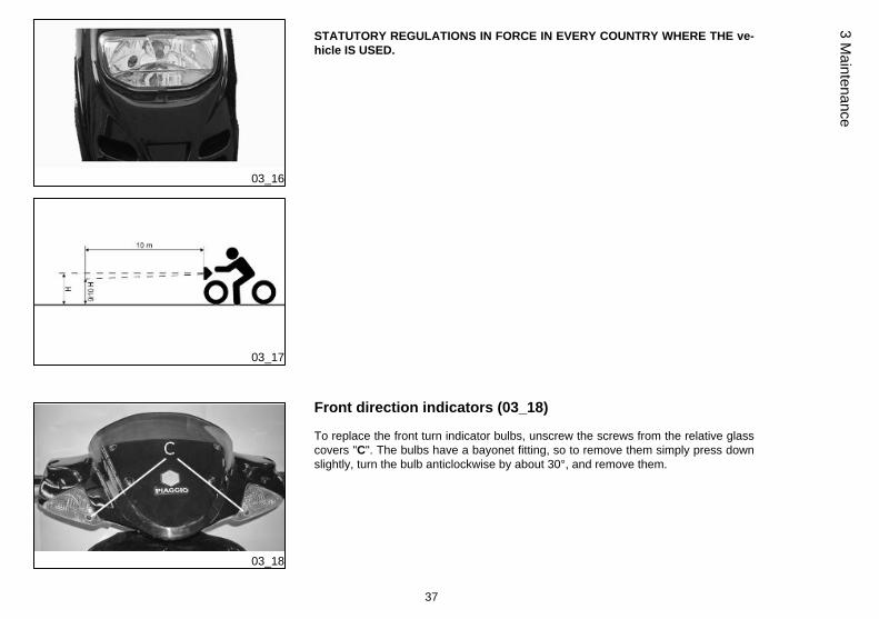
STATUTORY REGULATIONS IN FORCE IN EVERY COUNTRY WHERE THE ve-hicle IS USED.
03_18
Front direction indicators (03_18)
To replace the front turn indicator bulbs, unscrew the screws from the relative glasscovers "C". The bulbs have a bayonet fitting, so to remove them simply press downslightly, turn the bulb anticlockwise by about 30°, and remove them.
37
3 Maintenance
Rear optical unit
N.B.
IF MISTING IS NOTICED ON THE INSIDE OF THE HEADLAMP GLASS, THISDOES NOT INDICATE A FAULT AND IS RELATED TO THE HUMIDITY AND/ORTO LOW TEMPERATURES.
THE PHENOMENON SHOULD QUICKLY DISAPPEAR WHEN THE LIGHT ISSWITCHED ON.
THE PRESENCE OF DROPS OF WATER, ON THE OTHER HAND, COULD INDI-CATE THAT WATER IS INFILTRATING. CONTACT THE PIAGGIO AFTER-SALESSERVICE NETWORK.
WARNING
THE MALFUNCTION OF ONLY ONE LED DOES NOT CHANGE THE HOMOLO-GATION VALUES OR PERFORMANCE OF THE REAR LIGHT ASSEMBLY. IN THEEVENT OF THE BREAKAGE OR MALFUNCTION OF TWO OR MORE LEDs, THEREAR LIGHT ASSEMBLY SHOULD BE REPLACED.
03_19
Rear turn indicators (03_19)
To gain access to the turn indicator bulbs, remove the fastening screws «E».The bulbs have a bayonet coupling, to remove them press gently and twist anticlock-wise about 30°. To refit follow the same steps but in reverse order.
38
3 M
aint
enan
ce
Rear-view mirrors (03_20)
The mirrors can be set to the desired position by adjusting the mirror frame.
03_20
The mirrors must be adjusted so that the shafts are perpendicular to the vehicle'sdirection axis.
To adjust the mirror opening angle loosen the screw fitted at the end of the shaft andfasten it once the desired position is reached.
03_21
Idle adjustment (03_21)
The idle speed is adjusted by means of the idle speed adjuster screw «A» located onthe carburettor.To do this, proceed as shown in the diagram. Turn the register for adjusting the clear-ance of the throttle control transmission «B», then replace the rubber protection cap.Adjust the idle speed with the rear wheel off the ground (vehicle on stand) and with awarm engine. Turn the knob-type head screw in or out until the engine idles smoothly(around 1700÷1900 rpm.), i.e. without the rear wheel being moved by the en-gine.If adjustment still proves difficult, contact an Authorised Piaggio Service Centre tohave the level of CO when idling fixed (carbon monoxide emissions).
39
3 Maintenance
CAUTION
WHEN ADJUSTING IDLE SPEED, BE CAREFUL NOT TO TOUCH HOT PARTS OFTHE ENGINE TO AVOID BURNS.
03_22
03_23
Front disc brake (03_22, 03_23)
The brake disc and pad wear is automatically compensated, therefore it has no effecton the functioning of the front and rear brakes. For this reason it is not necessary toadjust the brakes. An excessively elastic brake lever stroke may indicate the presenceof air in the braking circuit or an irregular brake operation. In this case, particularlyconsidering the importance of the brakes in terms of safety, it is strongly recommendedthat you take the vehicle to an Authorised Service Centre as soon as possible forthe appropriate checks.
WARNING
CHECK BRAKE PADS FOR WEAR ON A REGULAR BASIS (AS INDICATED INTHE SCHEDULE MAINTENANCE TABLES). IF THE THICKNESS OF ONE ORBOTH PADS IS IN THE REGION OF 1.5 MM, BOTH PADS MUST BE CHANGED.IT IS RECOMMENDED TO CARRY OUT THIS OPERATION AT AN AUTHORISEDSERVICE CENTRE AS SOON AS POSSIBLE.
AFTER FITTING NEW BRAKE PADS DO NOT USE THE VEHICLE UNTIL YOUHAVE ACTIVATED THE BRAKE LEVER REPEATEDLY TO POSITION THE PADSAND RESTORE THE LEVER STROKE TO ITS CORRECT POSITION.
40
3 M
aint
enan
ce
CAUTION
THE BRAKING ACTION SHOULD BEGIN AFTER ABOUT 1/3 OF THE BRAKELEVER STROKE.
03_24
Rear drum brake (03_24)
Operate adjustment nut «B» and loosen lock nut «A» shown in the figure. Note thatwhen the throttle is in idle the wheel should rotate free. After the adjustment, screwlock nut «A».
CAUTION
THE BRAKING ACTION SHOULD BEGIN AFTER ABOUT 1/3 OF THE BRAKELEVER STROKE.
41
3 Maintenance
03_25
Puncture (03_25)
The vehicle is equipped with Tubeless tyres. When there is a puncture, Tubeless tyres- unlike tyres with inner tubes - go flat very slowly. This offers greater riding safety. Atyre that goes flat very slowly can be repaired with an "Inflate and Repair" spray. Tyresshould be later fully repaired or replaced at an Authorised Service Centre.
03_26
Periods of inactivity (03_26)
We recommend carrying out the following operations:1. General cleaning of the vehicle.
2. With the engine off and the piston at the bottom dead centre position, remove thespark plug, and pour 1÷ 2 cm³ of recommended oil through its opening. Press theengine start pedal 3 or 4 times letting the engine perform a few revolutions slowly,then replace the spark plug.
3. Drain off all the vehicle fuel; spread antirust grease on the unpainted metal parts;keep the wheels off the ground, by resting the chassis on two wooden wedges.
4. For the battery, follow the procedures described in the «Battery» section.
5. Drain the petrol from the carburettor float chamber through the bleed cap.
Recommended productsAGIP CITY HI TEC 4T
Oil to lubricate flexible transmissions (brake, throttle control and mixer, odometer)Oil for 2-stroke engines: SAE 5W-40, API SL, ACEA A3, JASO MA
42
3 M
aint
enan
ce
Cleaning the vehicle
In order to soften the dirt and mud deposited on the painted surfaces, use a low pres-sure jet of water. Once softened, mud and dirt must be removed with a soft spongefor bodywork soaked in lots of water and "shampoo" (2-4% of car shampoo in water).Then rinse abundantly with water, and dry with a shammy cloth. For the outside of theengine, use petroleum, a brush and clean cloths. Petroleum can damage paintwork.Remember that any polishing with silicone wax must always be preceded by washing
CAUTION
DETERGENTS POLLUTE WATER. THEREFORE THE VEHICLE SHOULD BEWASHED IN AN AREA EQUIPPED FOR THE COLLECTION AND PURIFICATIONOF THE LIQUIDS USED.
WARNING
NEVER WASH THE VEHICLE UNDER DIRECT SUNLIGHT, ESPECIALLY IN SUM-MER WHEN THE BODYWORK IS STILL HOT, AS THE CAR SHAMPOO MAY DRYBEFORE BEING RINSED OFF, AND COULD DAMAGE THE PAINTWORK. NEVERUSE RAGS SOAKED IN PETROL OR DIESEL OIL TO CLEAN THE PAINTED ORPLASTIC SURFACES, TO PREVENT THEM LOSING THEIR SHINE AND ME-CHANICAL CHARACTERISTICS.
WARNING
WHEN WASHING THE ENGINE WITH A HIGH-PRESSURE WATER JET:
• ONLY USE FAN SPRAY JETS.• DO NOT PLACE THE WATER JET NOZZLE CLOSER THAN 60 CM.• DO NOT USE WATER AT TEMPERATURES OVER 40° C.
43
3 Maintenance
• DO NOT DIRECT THE JETS DIRECTLY TO CARBURETTOR, WIRING, SLOTDIFFUSER ON THE TRANSMISSION COVER AND SCROLL COVER.
WARNING
USE AN ANTISTATIC CLOTH TO CLEAN THE DISPLAY AREA ON THE CON-TROL PANEL. IF AN ANTISTATIC CLOTH IS NOT USED, BLACK LINES MAYAPPEAR ON THE DISPLAY, BUT THESE SHOULD DISAPPEAR QUICKLY AFTERTHE ENGINE IS SWITCHED ON AND OFF A FEW TIMES IN NORMAL USE.
DIFFICULTY STARTINGNo fuel in tank Refuelling
Filters, jets or carburettor dirty orclogged.
Contact an Authorised ServiceCentre.
Insufficient battery charge Kick-start. Recharge the battery.
IGNITION PROBLEMNo spark from spark plug. Due tothe presence of high voltage, thischeck should only be carried out byan expert.
Check that the electrodes areproperly adjusted (0.7÷ 0.8 mm).Check that the electrodes areclean (clean with pure petrol andmetal brush or with emery cloth).Check the spark plug insulator:Replace the spark plug if theinsulator is cracked or broken. Ifthe spark plug is in good
INCREASED EXHAUST NOISEDeterioration of the SAS systemand/or of the tab
Contact an Authorised ServiceCentre.
STAND DOES NOT RETURN TO POSITIONPresence of dirt Clean and grease
46
3 M
aint
enan
ce
STARTER LEVER DOES NOT RETURN TO CORRECTPOSITION
Presence of dirt Clean and grease
47
3 Maintenance
48
3 M
aint
enan
ce
Typhoon 50
Chap. 04Technical data
49
TECHNICAL DATA
Electronic ignition A capacitor dischargemicroprocessor device, with built-in HV coil.
Supply. With high-octane, 95 N.O.R. lead-free petrol mix - oil via carburettor,automatic mixer (with variablecapacity depending on the enginespeed and opening of throttlevalve) petrol pump.
Intake By means of a compression valveon the casing
Lubrication Engine lubrication (piston,cylinder, crankshaft, mainbearings) with mixer oil.
Petrol tank In plastic, with a capacity of 5.5 lit.(approximate value) includingreserve ~ 2 lit.
Oil mixer tank In plastic, with a capacity of 1.5 lit.(including reserve ~0.500 lit).
Topping up mixer oil tank with at least 0.5 ÷ 1 lit.
50
4 Te
chni
cal d
ata
Front suspension upside-down hydraulic telescopicfork.
Rear suspension With coaxial spring and hydraulicshock absorber. Chassis to enginesupport with swinging arm.
Wheels with 3.50x10" wheel rims in lightalloy.
Front tyre 120/90-10"
Rear tyre 120/90-10"
Chassis made of welded tubular steel withsheet metal reinforcement.
Front brake Disc D=190 / 200 mm withhydraulic control, operated by rightbrake lever on the handlebars.
Rear brake Drum D=110 mm with expansionbrake shoes, mechanicallycontrolled by the left brake lever onthe handlebars.
Exhaust silencer Expanding, absorption type withdouble catalytic converter.
Maximum length 1820
Maximum width 730
Wheel base 1260
Maximum load Driver only.
Kerb weight 84 Kg
51
4 Technical data
04_01
ENGINE SPECIFICATIONS
Engine Single cylinder 2-stroke
Bore x stroke 40 X 39.3 mm
Engine capacity 49 cm³
Compression ratio . 10.3 : 1 (±0.8)
Dellorto Carburettor PHVA 17.5
Ignition advance (before TDC) 17° ± 1° at 4000 rpm
52
4 Te
chni
cal d
ata
spark plug CHAMPION RN2C
Max. speed According to current legislation
Kit equipment
The tools are located under the saddle. To free the tools from their housing, releasethe lever and then remove the clamp.
The tool bag contains: a double-headed screwdriver and a 13-21 mm box spanner.
53
4 Technical data
54
4 Te
chni
cal d
ata
Typhoon 50
Chap. 05Spare parts and
accessories
55
05_01
Warnings (05_01)
WARNING
IT IS ALSO RECOMMENDED THAT "ORIGINAL PIAGGIO SPARE PARTS" BEUSED, AS THESE ARE THE ONLY ONES OFFERING YOU THE SAME QUALITYASSURANCE AS THOSE INITIALLY FITTED ON THE VEHICLE.
IT SHOULD BE REMEMBERED THAT USING NON-ORIGINAL SPARE PARTSCAUSES YOUR WARRANTY RIGHTS TO EXPIRE.
WARNING
PIAGGIO MARKETS ITS OWN LINE OF ACCESSORIES THAT ARE RECOG-NISED AND GUARANTEED FOR USE. IT IS THEREFORE ESSENTIAL, IN ORDERTO CHOOSE AND MOUNT THE ACCESSORIES CORRECTLY, TO CONTACT ANAUTHORISED DEALER OR SERVICE CENTRE. THE USE OF NON-ORIGINALACCESSORIES MAY AFFECT THE STABILITY AND OPERATION OF YOUR VE-HICLE AND REDUCE SAFETY LEVELS WITH POTENTIAL RISKS FOR THERIDER.
56
5 Sp
are
parts
and
acc
esso
ries
Typhoon 50
Chap. 06Programmedmaintenance
57
Scheduled maintenance table
Adequate maintenance is fundamental to ensuring long-lasting, optimum operationand performance of your vehicle.
To this end, a series of checks and maintenance operations (at the owner's expense)have been suggested, which are included in the summary table on the following page.Any minor faults should be reported without delay to an Authorised Service Centreor Dealer without waiting until the next scheduled service to solve it.
All scheduled maintenance services must be carried out at the specified intervals,even if the stated mileage has not yet been reached. Punctual scooter servicing isessential to ensure your warranty remains valid. For any further information concern-ing Warranty procedures and "Scheduled Maintenance", please refer to the "WarrantyBooklet".
EVERY 2 YEARSBrake fluid - change
AFTER 1000 KM
Hub oil - change
Oil mixer/throttle linkage - adjustment
Odometer gear - greasing
Steering - adjustment
Brake control levers - greasing
Brake fluid level - check
58
6 Pr
ogra
mm
ed m
aint
enan
ce
Safety locks - check
Electrical system and battery - check
Tyre pressure and wear - check
Vehicle and brake test - road test
AFTER 5000 KM, 25000 KM, 35000 KM, 55000 KM
Hub oil level - check
Spark plug/electrode gap - replacement
Air filter - clean
Oil mixer/throttle linkage - adjustment
Brake control levers - greasing
Brake pads - check condition and wear
Brake fluid level - check
Electrical system and battery - check
Tyre pressure and wear - check
Vehicle and brake test - road test
AFTER 10000 KM, 50000 KM
Hub oil - change
Spark plug/electrode gap - replacement
59
6 Programm
ed maintenance
Air filter - clean
Idling speed (*) - adjustment
Oil mixer/throttle linkage - adjustment
Variable speed rollers - replacement
Odometer gear - greasing
Driving belt - checking
Steering - adjustment
Brake control levers - greasing
Brake pads - check condition and wear
Brake fluid level - check
Transmission elements - lubrication
Safety locks - check
Suspensions - check
Electrical system and battery - check
Headlight - adjustment
Tyre pressure and wear - check
Vehicle and brake test - road test
(*) See instructions in the "Adjusting the idle speed" section
AFTER 15000 KM AND 45000 KM
Hub oil level - check
60
6 Pr
ogra
mm
ed m
aint
enan
ce
Spark plug/electrode gap - replacement
Air filter - cleaning
Oil mixer/throttle linkage - adjustment
Driving belt - replacement
Brake control levers - greasing
Brake pads - check condition and wear
Brake fluid level - check
Electrical system and battery - check
Tyre pressure and wear - check
SAS box (sponge) (**) - cleaning
Vehicle and brake test - road test
(**) See regulations in the «Secondary air system» section
AFTER 20000 KM AND 40000 KM
Hub oil - change
Spark plug/electrode gap - replacement
Air filter - clean
Idling speed (*) - adjustment
Cylinder cooling system - check/cleaning
Oil mixer/throttle linkage - adjustment
Driving belt - checking
61
6 Programm
ed maintenance
Variable speed rollers - replacement
Mixer belt - replacement
Odometer gear - greasing
Steering - adjustment
Brake control levers - greasing
Brake pads - check condition and wear
Brake fluid level - check
Transmission elements - lubrication
Safety locks - check
Suspensions - check
Electrical system and battery - check
Headlight - adjustment
Tyre pressure and wear - check
Vehicle and brake test - road test
(*) See section «Adjusting the idle speed»
AFTER 30000 KM
Hub oil - change
Spark plug/electrode gap - replacement
Air filter - clean
Idling speed (*) - adjustment
62
6 Pr
ogra
mm
ed m
aint
enan
ce
Oil mixer/throttle linkage - adjustment
Driving belt - replacement
Variable speed rollers - replacement
Odometer gear - greasing
Steering - adjustment
Brake control levers - greasing
Brake pads - check condition and wear
Flexible brake tubes - replacement
Brake fluid level - check
Transmission elements - lubrication
Safety locks - check
Suspensions - check
Electrical system and battery - check
Headlight - adjustment
Tyre pressure and wear - check
SAS box (sponge) (**) - cleaning
Vehicle and brake test - road test
(*) See regulations in the «Adjusting the idle speed» section
(**) See regulations in the «Secondary air system» section
63
6 Programm
ed maintenance
AFTER 60000 KM
Hub oil - change
Spark plug/electrode gap - replacement
Air filter - clean
Idling speed (*) - adjustment
Cylinder cooling system - check/cleaning
Oil mixer/throttle linkage - adjustment
Driving belt - replacement
Variable speed rollers - replacement
Mixer belt - replacement
Odometer gear - greasing
Steering - adjustment
Brake control levers - greasing
Brake pads - check condition and wear
Flexible brake tubes - replacement
Brake fluid level - check
Transmission elements - lubrication
Safety locks - check
Suspensions - check
Electrical system and battery - check
Headlight - adjustment
Tyre pressure and wear - check
64
6 Pr
ogra
mm
ed m
aint
enan
ce
SAS box (sponge) (**) - cleaning
Vehicle and brake test - road test
(*) See regulations in the «Adjusting the idle speed» section
(**) See regulations in the «Secondary air system» section
The descriptions and illustrations given in this publication are not binding. While the basic specifications as described and illustrated in this manualremain unchanged, PIAGGIO-GILERA reserves the right, at any time and without being required to update this publication beforehand, to make anychanges to components, parts or accessories, which it considers necessary to improve the product or which are required for manufacturing or con-struction reasons.
Not all versions/models shown in this publication are available in all countries. The availability of single versions should be checked at the official Piaggio sales network.